EP4139623B1 - Wick assembly and heat pipe assembly - Google Patents
Wick assembly and heat pipe assembly Download PDFInfo
- Publication number
- EP4139623B1 EP4139623B1 EP21724132.2A EP21724132A EP4139623B1 EP 4139623 B1 EP4139623 B1 EP 4139623B1 EP 21724132 A EP21724132 A EP 21724132A EP 4139623 B1 EP4139623 B1 EP 4139623B1
- Authority
- EP
- European Patent Office
- Prior art keywords
- wick
- heat pipe
- container
- assembly
- end plug
- Prior art date
- Legal status (The legal status is an assumption and is not a legal conclusion. Google has not performed a legal analysis and makes no representation as to the accuracy of the status listed.)
- Active
Links
Images

Classifications
-
- F—MECHANICAL ENGINEERING; LIGHTING; HEATING; WEAPONS; BLASTING
- F28—HEAT EXCHANGE IN GENERAL
- F28D—HEAT-EXCHANGE APPARATUS, NOT PROVIDED FOR IN ANOTHER SUBCLASS, IN WHICH THE HEAT-EXCHANGE MEDIA DO NOT COME INTO DIRECT CONTACT
- F28D15/00—Heat-exchange apparatus with the intermediate heat-transfer medium in closed tubes passing into or through the conduit walls ; Heat-exchange apparatus employing intermediate heat-transfer medium or bodies
- F28D15/02—Heat-exchange apparatus with the intermediate heat-transfer medium in closed tubes passing into or through the conduit walls ; Heat-exchange apparatus employing intermediate heat-transfer medium or bodies in which the medium condenses and evaporates, e.g. heat pipes
- F28D15/04—Heat-exchange apparatus with the intermediate heat-transfer medium in closed tubes passing into or through the conduit walls ; Heat-exchange apparatus employing intermediate heat-transfer medium or bodies in which the medium condenses and evaporates, e.g. heat pipes with tubes having a capillary structure
- F28D15/046—Heat-exchange apparatus with the intermediate heat-transfer medium in closed tubes passing into or through the conduit walls ; Heat-exchange apparatus employing intermediate heat-transfer medium or bodies in which the medium condenses and evaporates, e.g. heat pipes with tubes having a capillary structure characterised by the material or the construction of the capillary structure
-
- F—MECHANICAL ENGINEERING; LIGHTING; HEATING; WEAPONS; BLASTING
- F28—HEAT EXCHANGE IN GENERAL
- F28F—DETAILS OF HEAT-EXCHANGE AND HEAT-TRANSFER APPARATUS, OF GENERAL APPLICATION
- F28F21/00—Constructions of heat-exchange apparatus characterised by the selection of particular materials
-
- F—MECHANICAL ENGINEERING; LIGHTING; HEATING; WEAPONS; BLASTING
- F28—HEAT EXCHANGE IN GENERAL
- F28F—DETAILS OF HEAT-EXCHANGE AND HEAT-TRANSFER APPARATUS, OF GENERAL APPLICATION
- F28F2275/00—Fastening; Joining
- F28F2275/12—Fastening; Joining by methods involving deformation of the elements
- F28F2275/125—Fastening; Joining by methods involving deformation of the elements by bringing elements together and expanding
Definitions
- This invention relates generally to heat pipes used in heat transfer systems, and more particularly, to wicks within the heat pipes that are configured to transfer the working fluid of the heat pipe from a condenser region of the heat pipe to an evaporator region.
- a heat pipe is a hermetically sealed, two-phase heat transfer component used to transfer heat from a primary side (evaporator section) to a secondary side (condenser section).
- FIG. 1 illustrates a heat pipe 100 comprising the aforementioned evaporator section 102 and condenser section 106, along with an adiabatic section 104 extending therebetween.
- the heat pipe 100 further includes a working fluid (such as water, liquid potassium, sodium, or alkali metal) and a wick 108.
- the working fluid is configured to absorb heat in the evaporator section 102 and vaporize.
- the saturated vapor, carrying latent heat of vaporization flows towards the condenser section 106 through the adiabatic section 104.
- the vapor condenses into a liquid pool 110 and gives off its latent heat.
- the condensed liquid is then returned to the evaporator section 102 through the wick 108 by capillary action.
- the aforementioned flow path of the working fluid is illustrated by segmented arrows in FIG. 1 .
- the phase change processes and two-phase flow circulation continues as long as the temperature gradient between the evaporator and condenser sections is maintained. Due to the very high heat transfer coefficients for boiling and condensation, heat pipes are highly effective thermal conductors.
- micro-reactors are nuclear reactors that generate less than 10MWe and are capable of being deployed for remote applications. These micro-reactors can be packaged in relatively small containers, operate without active involvement of personnel, and operate without refueling/replacement for a longer period than conventional nuclear power plants.
- One such micro-reactor is the eVinci Micro Reactor system, designed by Westinghouse Electric Company.
- the eVinci system is a heat pipe cooled reactor power system that utilizes heat pipes to act as passive heat removal devices that efficiently move thermal energy out of the reactor core to heat exchangers.
- the heat pipes used in the micro-reactors experience extreme operating temperatures (>850°C) and requires an internal wick that is made from materials that can withstand these temperatures and are compatible with the working fluid.
- This wick can be constructed from a wire mesh that is rolled and diffusion bonded together into a tube-like structure.
- the wick tube allows for the working fluid within the heat pipe to pass through it radially (such as after the latent heat is given off and the working fluid is absorbed by the wick) and along its axis (transferring the working fluid back toward the evaporator section with capillary action) while remaining rigid.
- the heat pipe container 112 it is desirable to fabricate the heat pipe container 112 from a different material than the wick 108. As an example, it may be important to maintain good mechanical properties of the container 112, such as ability to withstand high operating pressures of the heat pipe, to mitigate structural concerns. These same mechanical requirements are not imposed on the wick 108. In addition, the outside of the container 112 will be exposed to a different environment that may see a large range of material and chemical interactions. This may necessitate the use of a container 112 material that is not compatible with the working fluid on the inside thereof.
- a container lid 114 (that is comprised of same material as the container 112) is utilized to seal the wick 108 and working fluid within the container 112 of the heat pipe 100.
- the container lid 114 includes an end plug 116 extending therefrom that is configured to couple to the wick 108 at an interface 118. It is necessary to maintain a seal at the interface 116 between the end plug 116 of the heat pipe 100 and the evaporator section 102 of the wick 108.
- Methods of directly coupling the wick 108 and the end plug 116 at the interface 118 includes welding, diffusion bonding and brazing. These methods are not ideally suited to bonding dissimilar metals that are susceptible to different thermal expansion properties (differential thermal coefficients (DTE)).
- failure is any defect that results in a pore size greater than the pores within the wick 108, which are typically on the order of 10 micrometers. Therefore, utilizing dissimilar wick 108 and container lid / end plug 116 materials runs the risk of failure over time.
- a wick assembly for use with a heat pipe assembly including a container and a container lid is disclosed, the wick assembly being as claimed in claim 1.
- the wick of the wick assembly may comprise a first material and the end plug of the wick assembly a second material, wherein the first material is substantially identical to the second material.
- the rod of the wick assembly may comprise a first cross-sectional shape and the recess of the wick assembly a second cross-sectional shape, wherein the first cross-sectional shape and the second cross-sectional shape are substantially identical.
- a heat pipe assembly including a container, a wick, and an end plug coupled to the wick, the heat pipe assembly being as claimed in claim 6.
- the rod may be configured to center the wick within the container.
- the rod may be slidable within the recess based on growth and shrinkage of the wick.
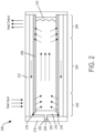
- FIG. 2 illustrates a heat pipe 200 accordingly at least one aspect of the present disclosure.
- the heat pipe 200 includes an evaporator section 202, a condenser section 206, and an adiabatic section 204 extending therebetween.
- the heat pipe 200 further includes a working fluid (such as water, liquid potassium, sodium, or alkali metal) and a wick 208 positioned within a container 212.
- the working fluid is configured to absorb heat in the evaporator section 202 and vaporize.
- the saturated vapor, carrying latent heat of vaporization flows towards the condenser section 206 through the adiabatic section 204.
- the condenser section 206 the vapor condenses into a liquid pool 210 and gives off its latent heat.
- the condensed liquid is then returned to the evaporator section 202 through the wick 208 by capillary action.
- the aforementioned flow path of the working fluid is illustrated by segmented arrows in FIG. 2 .
- the phase change processes and two-phase flow circulation continues as long as the temperature gradient between the evaporator and condenser sections is maintained.
- the wick 208 material is selected such that the wick 208 is compatible with the working fluid of the heat pipe 200 (such as alkali metal), as well as is able to withstand the high operating temperatures of the heat pipe 200 (>850°C).
- the wick 200 can expand and contract based on the thermal expansion properties of the wick 208.
- a wick 208 fabricated from 300 series stainless steel has high thermal expansion properties, leading to large fluctuations in size during operation of the heat pipe 200.
- the heat pipe 200 further includes an end plug 216 that can interface and couple to the wick 208 at an interface 218.
- the wick 208 can be coupled to the end plug 216 by any suitable coupling method, such as with welding, diffusion bonding, brazing, fasteners, adhesive, or any suitable form of coupling.
- the end plug 216 further includes a centering pin 220 extending therefrom.
- the end plug 216 can be constructed with the same, or at least substantially the same, material as the wick 208 such that the thermal expansion properties of the wick 208 and the end plug 216 are the same, or at least substantially the same.
- the end plug 216 being fabricated from the same, or at least substantially the same, material as the wick 208 avoids failure mechanisms associated with DTE and dissimilar material compatibility between the wick 208 and the end plug 216.
- the wick 208 and end plug 216 can comprise dissimilar materials that include similar, or at least substantially similar thermal expansion coefficients such that the wick 208 and end plug 216 expand and contract at similar rates, while also mitigating failures associated with DTE.
- the heat pipe 200 further including a container lid 214.
- the container lid 214 and the end plug 216 are separate and distinct components.
- the container lid 214 includes a groove or recess 222 defined therein that can receive the pin 220 extending from the end plug 216. thereby coupling the end plug 216 to the container lid 214.
- the pin 220 and the groove 222 are configured to center the wick 208 within the container 212, which is important for the thermal performance of the heat pipe 200.
- the groove 222 comprises a length that is the same, or at least substantially the same, as the length of the pin 220. Other embodiments are envisioned where the length of the groove 222 and the length of the pin 220 are different.
- the pin 220 can slide within the groove 222, accommodating the axial movement of the wick 208 and end plug 216.
- the groove 222 can include a sufficient length such that the pin 220 abuts the end 224 of the groove 222 at the same, or at least substantially the same, time as the end plug 216 contacts the container lid 214.
- the groove 222 can include a length such that the pin 220 abuts the end 224 of the grove 222 prior to the end plug 216 contacting the container lid 214.
- the end plug 216 can contact the container lid 214 prior to the pin 220 abutting the end 224 of the groove 222.
- the use of the pin 220 / groove 222 allows the container 212 and the container lid 214 to be constructed or manufactured from materials dissimilar to the wick 208 and the end plug 216.
- By isolating the sealing interface 218 as a separate part that can move with respect to the container 212 and container lid 214 failure mechanisms associated with DTE in a bonded plug/heat pipe design are eliminated.
- Existing methods of forming annular heat pipe wicks, as described with respect to FIG. 1 require the wick to be bonded to the container / end plug.
- the pin 220 and the groove 222 can include any suitable cross-sectional shape such that the pin 220 can axially slide through the groove 222 based on growth and shrinkage of the wick 208.
- the pin 220 and the groove 222 can include circular cross-sectional shapes. The use of circular cross-sectional shapes allows the pin 220 to be slidable within the groove 222, but allows the end plug 216 to be rotatable relative to the container lid 214.
- the pin 220 and the groove 222 can include a square cross-sectional shape. The use of a square cross-sectional shape allows the pin 220 to be slidable within the groove 222, while also preventing the end plug 216 from rotating relative to the container lid 214.
- pin 220 allows for tight part tolerances even considering a large DTE between the wick 208 material and container lid 214 material or container 212 material.
- the above-described invention applies to heat pipe materials with larger or smaller thermal expansion coefficients compared to the wick.
- the container groove 222 is be designed to accept growth or shrinking of the wick 208 length (relative to the heat pipe container 212) by properly sizing the groove 220 dimension and also properly setting the initial position of the pin 220.
- FIG. 2 illustrates a heat pipe 200 with one container lid 214 / groove 222 / end plug 216 / pin 220
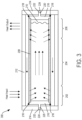
- the heat pipe such as heat pipe 300 illustrated in FIG. 3
- the heat pipe 300 illustrated in FIG. 3 includes a container lid 214 / groove 222 / end plug 216 / pin 220 on both ends of the heat pipe.
- the use of more than one container lid 214 / groove 222 / end plug 216 / pin 220 allows the wick to thermally expand in more than one direction.
- Example 1 - A heat pipe comprising a container, a container lid comprising a groove defined therein, a wick, and an end plug operably coupled to the wick.
- the end plug comprises a pin extending therefrom.
- the groove of the container lid is configured to receive the pin.
- Example 2 The heat pipe of Example 1, wherein the wick comprises a first material.
- the end plug comprises a second material.
- the first material is substantially identical to the second material.
- Example 3 The heat pipe of Example 1, wherein the wick comprises a first material.
- the container comprises a second material. The first material and the second material are different.
- Example 4 The heat pipe of Example 3, wherein the end plug comprises the first material.
- Example 5 The heat pipe of any one of Examples 1-4, wherein the pin comprises a first cross-sectional shape.
- the groove comprises a second cross-sectional shape.
- the first cross-sectional shape and the second cross-sectional shape are substantially identical.
- Example 6 The heat pipe of any one of Examples 1-5, wherein the pin is configured to center the wick within the container.
- Example 7 The heat pipe of any one of Examples 1-6, wherein the pin is slidable within the groove based on growth and shrinkage of the wick.
- Example 8 - A wick assembly for use with a heat pipe assembly comprising a container and a container lid.
- the wick assembly comprises a wick and an end plug coupled to the wick.
- the end plug comprises a rod extending therefrom,.
- the rod is configured to be inserted into a recess defined in the container lid.
- Example 9 The wick assembly of Example 8. wherein the wick comprises a first material.
- the end plug comprises a second material.
- the first material is substantially identical to the second material.
- Example 10 The wick assembly of Example 8, wherein the wick comprises a first material.
- the container comprises a second material.
- the first material and the second material are different.
- Example 11 The wick assembly of Example 10, wherein the end plug comprises the first material.
- Example 12 The wick assembly of any one of Examples 8-11, wherein the rod comprises a first cross-sectional shape.
- the recess comprises a second cross-sectional shape.
- the first cross-sectional shape and the second cross-sectional shape are substantially identical.
- Example 13 The wick assembly of any one of Examples 8-12, wherein the rod is configured to center the wick within the container.
- Example 14 The wick assembly of any one of Examples 8-13, wherein the rod is slidable within the recess based on growth and shrinkage of the wick.
- Example 15 - A heat pipe comprising a container, a wick, and an end plug coupled to the wick.
- the container comprises a first material and a lid comprising a recess defined therein.
- the wick comprising a second material.
- the second material is different that the first material.
- the end plug comprises a shaft extending therefrom.
- the recess of the container lid is configured to receive the shaft.
- Example 16 The heat pipe of Example 15, wherein the end plug comprises a third material substantially identical to the second material.
- Example 17 The heat pipe of Examples 15 or 16, wherein the shaft comprises a first cross-sectional shape.
- the recess comprises a second cross-sectional shape.
- the first cross-sectional shape and the second cross-sectional shape are substantially identical.
- Example 18 The heat pipe of any one of Examples 15-17, wherein the shaft is configured to center the wick within the container.
- Example 19 The heat pipe of any one of Examples 15-18, wherein the shaft is slidable within the groove based on growth and shrinkage of the wick.
- One or more components may be referred to herein as “configured to,” “configurable to,” “operable/operative to,” “adapted/adaptable,” “able to,” “conformable/conformed to.” etc. Those skilled in the art will recognize that “configured to'' can generally encompass active-state components and/or inactive-state components and/or standby-state components, unless context requires otherwise.
- any reference to “one aspect,” “an aspect,” “an exemplification,” “one exemplification,” and the like means that a particular feature, structure, or characteristic described in connection with the aspect is included in at least one aspect.
- appearances of the phrases “in one aspect,” “in an aspect,” “in an exemplification,” and “in one exemplification” in various places throughout the specification are not necessarily all referring to the same aspect.
- the particular features, structures or characteristics may be combined in any suitable manner in one or more aspects.
- the term “substantially”, “about”, or “approximately” as used in the present disclosure means an acceptable error for a particular value as determined by one of ordinary skill in the art, which depends in part on how the value is measured or determined. In certain embodiments, the term “substantially”, “about”, or “approximately” means within 1, 2, 3, or 4 standard deviations. In certain embodiments, the term “substantially”, “about”, or “approximately” means within 50%, 20%, 15%, 10%, 9%, 8%, 7%, 6%, 5%, 4%, 3%, 2%, 1%, 0.5%, or 0.05% of a given value or range.
Landscapes
- Engineering & Computer Science (AREA)
- Physics & Mathematics (AREA)
- Thermal Sciences (AREA)
- Mechanical Engineering (AREA)
- General Engineering & Computer Science (AREA)
- Life Sciences & Earth Sciences (AREA)
- Sustainable Development (AREA)
- Cooling Or The Like Of Electrical Apparatus (AREA)
- Cooling Or The Like Of Semiconductors Or Solid State Devices (AREA)
- Thermotherapy And Cooling Therapy Devices (AREA)
- Catching Or Destruction (AREA)
- Rigid Pipes And Flexible Pipes (AREA)
Priority Applications (1)
| Application Number | Priority Date | Filing Date | Title |
|---|---|---|---|
| SI202130293T SI4139623T1 (sl) | 2020-04-20 | 2021-04-20 | Sklop stenja in sklop toplotne cevi |
Applications Claiming Priority (2)
| Application Number | Priority Date | Filing Date | Title |
|---|---|---|---|
| US16/853,345 US11650016B2 (en) | 2020-04-20 | 2020-04-20 | Method of installing a heat pipe wick into a container of differing thermal expansion coefficient |
| PCT/US2021/028137 WO2021216538A1 (en) | 2020-04-20 | 2021-04-20 | Method of installing a heat pipe wick into a container of differing thermal expansion coefficient |
Publications (2)
| Publication Number | Publication Date |
|---|---|
| EP4139623A1 EP4139623A1 (en) | 2023-03-01 |
| EP4139623B1 true EP4139623B1 (en) | 2025-03-19 |
Family
ID=75850699
Family Applications (1)
| Application Number | Title | Priority Date | Filing Date |
|---|---|---|---|
| EP21724132.2A Active EP4139623B1 (en) | 2020-04-20 | 2021-04-20 | Wick assembly and heat pipe assembly |
Country Status (12)
| Country | Link |
|---|---|
| US (1) | US11650016B2 (pl) |
| EP (1) | EP4139623B1 (pl) |
| JP (1) | JP7753248B2 (pl) |
| KR (1) | KR20230003480A (pl) |
| CA (1) | CA3176238A1 (pl) |
| ES (1) | ES3019919T3 (pl) |
| FI (1) | FI4139623T3 (pl) |
| PL (1) | PL4139623T3 (pl) |
| SI (1) | SI4139623T1 (pl) |
| TW (1) | TWI817109B (pl) |
| WO (1) | WO2021216538A1 (pl) |
| ZA (1) | ZA202211867B (pl) |
Families Citing this family (5)
| Publication number | Priority date | Publication date | Assignee | Title |
|---|---|---|---|---|
| KR102704465B1 (ko) * | 2022-12-20 | 2024-09-05 | 주식회사유니에스티에스 | 교차형히트파이프와 이를 이용한 원자력장치 |
| US12392336B2 (en) | 2023-03-15 | 2025-08-19 | Westinghouse Electric Company Llc | Bellows pump for liquid metals |
| WO2026054868A1 (en) | 2024-09-07 | 2026-03-12 | Westinghouse Electric Company Llc | Methods and devices for forming a wick |
| US20260071824A1 (en) | 2024-09-07 | 2026-03-12 | Westinghouse Electric Company Llc | Heat pipe thermal expansion modification |
| US12611740B2 (en) | 2024-09-07 | 2026-04-28 | Westinghouse Electric Company Llc | Methods for attaching a wick plug to a wick |
Family Cites Families (17)
| Publication number | Priority date | Publication date | Assignee | Title |
|---|---|---|---|---|
| US3517730A (en) * | 1967-03-15 | 1970-06-30 | Us Navy | Controllable heat pipe |
| US4046168A (en) * | 1974-09-30 | 1977-09-06 | Mm Plastic (Mfg) Company, Inc. | Closure plugs |
| US4047198A (en) * | 1976-04-19 | 1977-09-06 | Hughes Aircraft Company | Transistor cooling by heat pipes having a wick of dielectric powder |
| JPS57179589A (en) * | 1981-04-28 | 1982-11-05 | Fujikura Ltd | Manufacture of heat pipe |
| FR2604771B1 (fr) * | 1986-10-06 | 1989-01-27 | Framatome Sa | Dispositif de bouchage etanche d'un orifice traversant une paroi |
| US4885129A (en) | 1988-10-24 | 1989-12-05 | The United States Of America As Represented By The Secretary Of The Air Force | Method of manufacturing heat pipe wicks |
| US5684848A (en) | 1996-05-06 | 1997-11-04 | General Electric Company | Nuclear reactor heat pipe |
| US5771967A (en) * | 1996-09-12 | 1998-06-30 | The United States Of America As Represented By The Secretary Of The Navy | Wick-interrupt temperature controlling heat pipe |
| US6907918B2 (en) * | 2002-02-13 | 2005-06-21 | Thermal Corp. | Deformable end cap for heat pipe |
| US6768781B1 (en) | 2003-03-31 | 2004-07-27 | The Boeing Company | Methods and apparatuses for removing thermal energy from a nuclear reactor |
| JP2005106430A (ja) * | 2003-10-01 | 2005-04-21 | Mitsubishi Electric Corp | ループ型ヒートパイプ |
| US7661464B2 (en) * | 2005-12-09 | 2010-02-16 | Alliant Techsystems Inc. | Evaporator for use in a heat transfer system |
| US9793014B2 (en) | 2008-05-15 | 2017-10-17 | Terrapower, Llc | Heat pipe fission fuel element |
| US20100155033A1 (en) | 2008-10-28 | 2010-06-24 | Kazak Composites, Inc. | Thermal management system using micro heat pipe for thermal management of electronic components |
| US10643756B2 (en) | 2013-04-25 | 2020-05-05 | Triad National Security, Llc | Mobile heat pipe cooled fast reactor system |
| WO2016121778A1 (ja) * | 2015-01-27 | 2016-08-04 | 古河電気工業株式会社 | 蓄熱容器及び蓄熱容器を備えた蓄熱装置 |
| US11355252B2 (en) * | 2016-12-30 | 2022-06-07 | Nuscale Power, Llc | Control rod drive mechanism with heat pipe cooling |
-
2020
- 2020-04-20 US US16/853,345 patent/US11650016B2/en active Active
-
2021
- 2021-04-20 WO PCT/US2021/028137 patent/WO2021216538A1/en not_active Ceased
- 2021-04-20 FI FIEP21724132.2T patent/FI4139623T3/fi active
- 2021-04-20 CA CA3176238A patent/CA3176238A1/en active Pending
- 2021-04-20 KR KR1020227036941A patent/KR20230003480A/ko active Pending
- 2021-04-20 TW TW110114214A patent/TWI817109B/zh active
- 2021-04-20 SI SI202130293T patent/SI4139623T1/sl unknown
- 2021-04-20 EP EP21724132.2A patent/EP4139623B1/en active Active
- 2021-04-20 JP JP2022564045A patent/JP7753248B2/ja active Active
- 2021-04-20 ES ES21724132T patent/ES3019919T3/es active Active
- 2021-04-20 PL PL21724132.2T patent/PL4139623T3/pl unknown
-
2022
- 2022-10-31 ZA ZA2022/11867A patent/ZA202211867B/en unknown
Also Published As
| Publication number | Publication date |
|---|---|
| PL4139623T3 (pl) | 2025-04-28 |
| FI4139623T3 (fi) | 2025-04-25 |
| TW202203251A (zh) | 2022-01-16 |
| JP7753248B2 (ja) | 2025-10-14 |
| TWI817109B (zh) | 2023-10-01 |
| KR20230003480A (ko) | 2023-01-06 |
| ZA202211867B (en) | 2023-07-26 |
| US20210325122A1 (en) | 2021-10-21 |
| US11650016B2 (en) | 2023-05-16 |
| CA3176238A1 (en) | 2021-10-28 |
| EP4139623A1 (en) | 2023-03-01 |
| WO2021216538A1 (en) | 2021-10-28 |
| SI4139623T1 (sl) | 2025-06-30 |
| JP2023522945A (ja) | 2023-06-01 |
| ES3019919T3 (en) | 2025-05-21 |
Similar Documents
| Publication | Publication Date | Title |
|---|---|---|
| EP4139623B1 (en) | Wick assembly and heat pipe assembly | |
| US9315280B2 (en) | Heat pipe with axial wick | |
| US11709022B2 (en) | Metal wick crimping method for heat pipe internals | |
| TWI813981B (zh) | 用於形成芯的形成總成及使用心軸來形成芯之方法 | |
| US20230170101A1 (en) | Compact passive decay heat removal system for transportable micro-reactor applications | |
| US20260071824A1 (en) | Heat pipe thermal expansion modification | |
| US11858075B1 (en) | Heat pipe wick bonding through crimping | |
| JPH09229576A (ja) | ヒートパイプ型熱交換器 | |
| JP2020020518A (ja) | 蒸発器、ループ型ヒートパイプ、冷却装置及び電子機器 | |
| JP2024540700A (ja) | 深冷容器の圧力増加装置及び深冷容器 |
Legal Events
| Date | Code | Title | Description |
|---|---|---|---|
| STAA | Information on the status of an ep patent application or granted ep patent |
Free format text: STATUS: UNKNOWN |
|
| STAA | Information on the status of an ep patent application or granted ep patent |
Free format text: STATUS: THE INTERNATIONAL PUBLICATION HAS BEEN MADE |
|
| PUAI | Public reference made under article 153(3) epc to a published international application that has entered the european phase |
Free format text: ORIGINAL CODE: 0009012 |
|
| STAA | Information on the status of an ep patent application or granted ep patent |
Free format text: STATUS: REQUEST FOR EXAMINATION WAS MADE |
|
| 17P | Request for examination filed |
Effective date: 20221021 |
|
| AK | Designated contracting states |
Kind code of ref document: A1 Designated state(s): AL AT BE BG CH CY CZ DE DK EE ES FI FR GB GR HR HU IE IS IT LI LT LU LV MC MK MT NL NO PL PT RO RS SE SI SK SM TR |
|
| DAV | Request for validation of the european patent (deleted) | ||
| DAX | Request for extension of the european patent (deleted) | ||
| GRAP | Despatch of communication of intention to grant a patent |
Free format text: ORIGINAL CODE: EPIDOSNIGR1 |
|
| STAA | Information on the status of an ep patent application or granted ep patent |
Free format text: STATUS: GRANT OF PATENT IS INTENDED |
|
| INTG | Intention to grant announced |
Effective date: 20241008 |
|
| GRAS | Grant fee paid |
Free format text: ORIGINAL CODE: EPIDOSNIGR3 |
|
| GRAA | (expected) grant |
Free format text: ORIGINAL CODE: 0009210 |
|
| STAA | Information on the status of an ep patent application or granted ep patent |
Free format text: STATUS: THE PATENT HAS BEEN GRANTED |
|
| AK | Designated contracting states |
Kind code of ref document: B1 Designated state(s): AL AT BE BG CH CY CZ DE DK EE ES FI FR GB GR HR HU IE IS IT LI LT LU LV MC MK MT NL NO PL PT RO RS SE SI SK SM TR |
|
| REG | Reference to a national code |
Ref country code: GB Ref legal event code: FG4D |
|
| REG | Reference to a national code |
Ref country code: CH Ref legal event code: EP |
|
| REG | Reference to a national code |
Ref country code: DE Ref legal event code: R096 Ref document number: 602021027803 Country of ref document: DE |
|
| REG | Reference to a national code |
Ref country code: IE Ref legal event code: FG4D |
|
| REG | Reference to a national code |
Ref country code: SE Ref legal event code: TRGR |
|
| REG | Reference to a national code |
Ref country code: NL Ref legal event code: FP |
|
| REG | Reference to a national code |
Ref country code: FI Ref legal event code: FGE |
|
| PGFP | Annual fee paid to national office [announced via postgrant information from national office to epo] |
Ref country code: NL Payment date: 20250429 Year of fee payment: 5 |
|
| REG | Reference to a national code |
Ref country code: ES Ref legal event code: FG2A Ref document number: 3019919 Country of ref document: ES Kind code of ref document: T3 Effective date: 20250521 |
|
| PG25 | Lapsed in a contracting state [announced via postgrant information from national office to epo] |
Ref country code: RS Free format text: LAPSE BECAUSE OF FAILURE TO SUBMIT A TRANSLATION OF THE DESCRIPTION OR TO PAY THE FEE WITHIN THE PRESCRIBED TIME-LIMIT Effective date: 20250619 |
|
| PGFP | Annual fee paid to national office [announced via postgrant information from national office to epo] |
Ref country code: FI Payment date: 20250430 Year of fee payment: 5 |
|
| PGFP | Annual fee paid to national office [announced via postgrant information from national office to epo] |
Ref country code: PL Payment date: 20250424 Year of fee payment: 5 Ref country code: DE Payment date: 20250430 Year of fee payment: 5 |
|
| PGFP | Annual fee paid to national office [announced via postgrant information from national office to epo] |
Ref country code: GB Payment date: 20250502 Year of fee payment: 5 Ref country code: ES Payment date: 20250513 Year of fee payment: 5 |
|
| REG | Reference to a national code |
Ref country code: LT Ref legal event code: MG9D |
|
| PG25 | Lapsed in a contracting state [announced via postgrant information from national office to epo] |
Ref country code: NO Free format text: LAPSE BECAUSE OF FAILURE TO SUBMIT A TRANSLATION OF THE DESCRIPTION OR TO PAY THE FEE WITHIN THE PRESCRIBED TIME-LIMIT Effective date: 20250619 |
|
| PGFP | Annual fee paid to national office [announced via postgrant information from national office to epo] |
Ref country code: IT Payment date: 20250429 Year of fee payment: 5 Ref country code: BE Payment date: 20250429 Year of fee payment: 5 |
|
| PG25 | Lapsed in a contracting state [announced via postgrant information from national office to epo] |
Ref country code: HR Free format text: LAPSE BECAUSE OF FAILURE TO SUBMIT A TRANSLATION OF THE DESCRIPTION OR TO PAY THE FEE WITHIN THE PRESCRIBED TIME-LIMIT Effective date: 20250319 |
|
| PG25 | Lapsed in a contracting state [announced via postgrant information from national office to epo] |
Ref country code: LV Free format text: LAPSE BECAUSE OF FAILURE TO SUBMIT A TRANSLATION OF THE DESCRIPTION OR TO PAY THE FEE WITHIN THE PRESCRIBED TIME-LIMIT Effective date: 20250319 |
|
| PGFP | Annual fee paid to national office [announced via postgrant information from national office to epo] |
Ref country code: FR Payment date: 20250429 Year of fee payment: 5 |
|
| PG25 | Lapsed in a contracting state [announced via postgrant information from national office to epo] |
Ref country code: GR Free format text: LAPSE BECAUSE OF FAILURE TO SUBMIT A TRANSLATION OF THE DESCRIPTION OR TO PAY THE FEE WITHIN THE PRESCRIBED TIME-LIMIT Effective date: 20250620 Ref country code: BG Free format text: LAPSE BECAUSE OF FAILURE TO SUBMIT A TRANSLATION OF THE DESCRIPTION OR TO PAY THE FEE WITHIN THE PRESCRIBED TIME-LIMIT Effective date: 20250319 |
|
| PGFP | Annual fee paid to national office [announced via postgrant information from national office to epo] |
Ref country code: RO Payment date: 20250430 Year of fee payment: 5 |
|
| PGFP | Annual fee paid to national office [announced via postgrant information from national office to epo] |
Ref country code: SE Payment date: 20250429 Year of fee payment: 5 Ref country code: SI Payment date: 20250424 Year of fee payment: 5 |
|
| REG | Reference to a national code |
Ref country code: AT Ref legal event code: MK05 Ref document number: 1777249 Country of ref document: AT Kind code of ref document: T Effective date: 20250319 |
|
| PG25 | Lapsed in a contracting state [announced via postgrant information from national office to epo] |
Ref country code: SM Free format text: LAPSE BECAUSE OF FAILURE TO SUBMIT A TRANSLATION OF THE DESCRIPTION OR TO PAY THE FEE WITHIN THE PRESCRIBED TIME-LIMIT Effective date: 20250319 |
|
| PG25 | Lapsed in a contracting state [announced via postgrant information from national office to epo] |
Ref country code: PT Free format text: LAPSE BECAUSE OF FAILURE TO SUBMIT A TRANSLATION OF THE DESCRIPTION OR TO PAY THE FEE WITHIN THE PRESCRIBED TIME-LIMIT Effective date: 20250721 |
|
| PG25 | Lapsed in a contracting state [announced via postgrant information from national office to epo] |
Ref country code: AT Free format text: LAPSE BECAUSE OF FAILURE TO SUBMIT A TRANSLATION OF THE DESCRIPTION OR TO PAY THE FEE WITHIN THE PRESCRIBED TIME-LIMIT Effective date: 20250319 |
|
| PG25 | Lapsed in a contracting state [announced via postgrant information from national office to epo] |
Ref country code: EE Free format text: LAPSE BECAUSE OF FAILURE TO SUBMIT A TRANSLATION OF THE DESCRIPTION OR TO PAY THE FEE WITHIN THE PRESCRIBED TIME-LIMIT Effective date: 20250319 |
|
| PG25 | Lapsed in a contracting state [announced via postgrant information from national office to epo] |
Ref country code: SK Free format text: LAPSE BECAUSE OF FAILURE TO SUBMIT A TRANSLATION OF THE DESCRIPTION OR TO PAY THE FEE WITHIN THE PRESCRIBED TIME-LIMIT Effective date: 20250319 |
|
| PG25 | Lapsed in a contracting state [announced via postgrant information from national office to epo] |
Ref country code: IS Free format text: LAPSE BECAUSE OF FAILURE TO SUBMIT A TRANSLATION OF THE DESCRIPTION OR TO PAY THE FEE WITHIN THE PRESCRIBED TIME-LIMIT Effective date: 20250719 |
|
| REG | Reference to a national code |
Ref country code: CH Ref legal event code: H13 Free format text: ST27 STATUS EVENT CODE: U-0-0-H10-H13 (AS PROVIDED BY THE NATIONAL OFFICE) Effective date: 20251125 |
|
| PG25 | Lapsed in a contracting state [announced via postgrant information from national office to epo] |
Ref country code: LU Free format text: LAPSE BECAUSE OF NON-PAYMENT OF DUE FEES Effective date: 20250420 |
|
| PG25 | Lapsed in a contracting state [announced via postgrant information from national office to epo] |
Ref country code: MC Free format text: LAPSE BECAUSE OF FAILURE TO SUBMIT A TRANSLATION OF THE DESCRIPTION OR TO PAY THE FEE WITHIN THE PRESCRIBED TIME-LIMIT Effective date: 20250319 |
|
| REG | Reference to a national code |
Ref country code: DE Ref legal event code: R097 Ref document number: 602021027803 Country of ref document: DE |
|
| PG25 | Lapsed in a contracting state [announced via postgrant information from national office to epo] |
Ref country code: DK Free format text: LAPSE BECAUSE OF FAILURE TO SUBMIT A TRANSLATION OF THE DESCRIPTION OR TO PAY THE FEE WITHIN THE PRESCRIBED TIME-LIMIT Effective date: 20250319 |
|
| PG25 | Lapsed in a contracting state [announced via postgrant information from national office to epo] |
Ref country code: CH Free format text: LAPSE BECAUSE OF NON-PAYMENT OF DUE FEES Effective date: 20250430 |
|
| PLBE | No opposition filed within time limit |
Free format text: ORIGINAL CODE: 0009261 |
|
| STAA | Information on the status of an ep patent application or granted ep patent |
Free format text: STATUS: NO OPPOSITION FILED WITHIN TIME LIMIT |
|
| REG | Reference to a national code |
Ref country code: CH Ref legal event code: L10 Free format text: ST27 STATUS EVENT CODE: U-0-0-L10-L00 (AS PROVIDED BY THE NATIONAL OFFICE) Effective date: 20260128 |
|
| 26N | No opposition filed |
Effective date: 20251222 |
|
| PG25 | Lapsed in a contracting state [announced via postgrant information from national office to epo] |
Ref country code: IE Free format text: LAPSE BECAUSE OF NON-PAYMENT OF DUE FEES Effective date: 20250420 |
|
| PGFP | Annual fee paid to national office [announced via postgrant information from national office to epo] |
Ref country code: CZ Payment date: 20260327 Year of fee payment: 6 |