EP4139675B1 - Autonome wasseranalysevorrichtung und schwimmbad mit solch einer vorrichtung - Google Patents
Autonome wasseranalysevorrichtung und schwimmbad mit solch einer vorrichtung Download PDFInfo
- Publication number
- EP4139675B1 EP4139675B1 EP21720581.4A EP21720581A EP4139675B1 EP 4139675 B1 EP4139675 B1 EP 4139675B1 EP 21720581 A EP21720581 A EP 21720581A EP 4139675 B1 EP4139675 B1 EP 4139675B1
- Authority
- EP
- European Patent Office
- Prior art keywords
- analysis
- water
- analysis device
- turbine
- data
- Prior art date
- Legal status (The legal status is an assumption and is not a legal conclusion. Google has not performed a legal analysis and makes no representation as to the accuracy of the status listed.)
- Active
Links
Images


Classifications
-
- C—CHEMISTRY; METALLURGY
- C02—TREATMENT OF WATER, WASTE WATER, SEWAGE, OR SLUDGE
- C02F—TREATMENT OF WATER, WASTE WATER, SEWAGE, OR SLUDGE
- C02F1/00—Treatment of water, waste water, or sewage
- C02F1/001—Processes for the treatment of water whereby the filtration technique is of importance
-
- G—PHYSICS
- G01—MEASURING; TESTING
- G01N—INVESTIGATING OR ANALYSING MATERIALS BY DETERMINING THEIR CHEMICAL OR PHYSICAL PROPERTIES
- G01N33/00—Investigating or analysing materials by specific methods not covered by groups G01N1/00 - G01N31/00
- G01N33/18—Water
- G01N33/1893—Water using flow cells
-
- C—CHEMISTRY; METALLURGY
- C02—TREATMENT OF WATER, WASTE WATER, SEWAGE, OR SLUDGE
- C02F—TREATMENT OF WATER, WASTE WATER, SEWAGE, OR SLUDGE
- C02F1/00—Treatment of water, waste water, or sewage
- C02F1/001—Processes for the treatment of water whereby the filtration technique is of importance
- C02F1/004—Processes for the treatment of water whereby the filtration technique is of importance using large scale industrial sized filters
-
- F—MECHANICAL ENGINEERING; LIGHTING; HEATING; WEAPONS; BLASTING
- F03—MACHINES OR ENGINES FOR LIQUIDS; WIND, SPRING, OR WEIGHT MOTORS; PRODUCING MECHANICAL POWER OR A REACTIVE PROPULSIVE THRUST, NOT OTHERWISE PROVIDED FOR
- F03B—MACHINES OR ENGINES FOR LIQUIDS
- F03B17/00—Other machines or engines
- F03B17/06—Other machines or engines using liquid flow with predominantly kinetic energy conversion, e.g. of swinging-flap type, "run-of-river", "ultra-low head"
- F03B17/062—Other machines or engines using liquid flow with predominantly kinetic energy conversion, e.g. of swinging-flap type, "run-of-river", "ultra-low head" with rotation axis substantially at right angle to flow direction
-
- C—CHEMISTRY; METALLURGY
- C02—TREATMENT OF WATER, WASTE WATER, SEWAGE, OR SLUDGE
- C02F—TREATMENT OF WATER, WASTE WATER, SEWAGE, OR SLUDGE
- C02F1/00—Treatment of water, waste water, or sewage
- C02F1/30—Treatment of water, waste water, or sewage by irradiation
- C02F1/32—Treatment of water, waste water, or sewage by irradiation with ultraviolet light
-
- C—CHEMISTRY; METALLURGY
- C02—TREATMENT OF WATER, WASTE WATER, SEWAGE, OR SLUDGE
- C02F—TREATMENT OF WATER, WASTE WATER, SEWAGE, OR SLUDGE
- C02F1/00—Treatment of water, waste water, or sewage
- C02F1/46—Treatment of water, waste water, or sewage by electrochemical methods
-
- C—CHEMISTRY; METALLURGY
- C02—TREATMENT OF WATER, WASTE WATER, SEWAGE, OR SLUDGE
- C02F—TREATMENT OF WATER, WASTE WATER, SEWAGE, OR SLUDGE
- C02F1/00—Treatment of water, waste water, or sewage
- C02F1/66—Treatment of water, waste water, or sewage by neutralisation; pH adjustment
-
- C—CHEMISTRY; METALLURGY
- C02—TREATMENT OF WATER, WASTE WATER, SEWAGE, OR SLUDGE
- C02F—TREATMENT OF WATER, WASTE WATER, SEWAGE, OR SLUDGE
- C02F2103/00—Nature of the water, waste water, sewage or sludge to be treated
- C02F2103/42—Nature of the water, waste water, sewage or sludge to be treated from bathing facilities, e.g. swimming pools
-
- C—CHEMISTRY; METALLURGY
- C02—TREATMENT OF WATER, WASTE WATER, SEWAGE, OR SLUDGE
- C02F—TREATMENT OF WATER, WASTE WATER, SEWAGE, OR SLUDGE
- C02F2201/00—Apparatus for treatment of water, waste water or sewage
- C02F2201/001—Build in apparatus for autonomous on board water supply and wastewater treatment (e.g. for aircrafts, cruiseships, oil drilling platforms, railway trains, space stations)
-
- C—CHEMISTRY; METALLURGY
- C02—TREATMENT OF WATER, WASTE WATER, SEWAGE, OR SLUDGE
- C02F—TREATMENT OF WATER, WASTE WATER, SEWAGE, OR SLUDGE
- C02F2201/00—Apparatus for treatment of water, waste water or sewage
- C02F2201/009—Apparatus with independent power supply, e.g. solar cells, windpower or fuel cells
-
- C—CHEMISTRY; METALLURGY
- C02—TREATMENT OF WATER, WASTE WATER, SEWAGE, OR SLUDGE
- C02F—TREATMENT OF WATER, WASTE WATER, SEWAGE, OR SLUDGE
- C02F2209/00—Controlling or monitoring parameters in water treatment
- C02F2209/003—Downstream control, i.e. outlet monitoring, e.g. to check the treating agents, such as halogens or ozone, leaving the process
-
- C—CHEMISTRY; METALLURGY
- C02—TREATMENT OF WATER, WASTE WATER, SEWAGE, OR SLUDGE
- C02F—TREATMENT OF WATER, WASTE WATER, SEWAGE, OR SLUDGE
- C02F2209/00—Controlling or monitoring parameters in water treatment
- C02F2209/005—Processes using a programmable logic controller [PLC]
- C02F2209/008—Processes using a programmable logic controller [PLC] comprising telecommunication features, e.g. modems or antennas
-
- C—CHEMISTRY; METALLURGY
- C02—TREATMENT OF WATER, WASTE WATER, SEWAGE, OR SLUDGE
- C02F—TREATMENT OF WATER, WASTE WATER, SEWAGE, OR SLUDGE
- C02F2303/00—Specific treatment goals
- C02F2303/14—Maintenance of water treatment installations
-
- Y—GENERAL TAGGING OF NEW TECHNOLOGICAL DEVELOPMENTS; GENERAL TAGGING OF CROSS-SECTIONAL TECHNOLOGIES SPANNING OVER SEVERAL SECTIONS OF THE IPC; TECHNICAL SUBJECTS COVERED BY FORMER USPC CROSS-REFERENCE ART COLLECTIONS [XRACs] AND DIGESTS
- Y02—TECHNOLOGIES OR APPLICATIONS FOR MITIGATION OR ADAPTATION AGAINST CLIMATE CHANGE
- Y02E—REDUCTION OF GREENHOUSE GAS [GHG] EMISSIONS, RELATED TO ENERGY GENERATION, TRANSMISSION OR DISTRIBUTION
- Y02E10/00—Energy generation through renewable energy sources
- Y02E10/30—Energy from the sea, e.g. using wave energy or salinity gradient
Definitions
- the present invention relates to an autonomous water analysis device, usable in particular for the analysis of swimming pool water. More particularly, the device of the present invention is a device which aims to measure and transmit physicochemical values of water, such as temperature, turbidity, flow rate, pressure, pH or the like. It also concerns a swimming pool equipped with such a device.
- the invention finds applications in the control of physicochemical parameters of swimming pool water and the monitoring of the quality and health safety of the water.
- the invention also finds applications in controlling the components of a swimming pool filtration circuit.
- Guaranteeing the water quality of a swimming pool requires monitoring a certain number of physicochemical parameters, such as water temperature, hydrogen potential (pH), oxidation potential reduction (ORP), the salinity (S) of the water, the rate of dissolved solids (TDS), and the turbidity of the water.
- physicochemical parameters such as water temperature, hydrogen potential (pH), oxidation potential reduction (ORP), the salinity (S) of the water, the rate of dissolved solids (TDS), and the turbidity of the water.
- Water analysis devices can be installed in the technical room of the swimming pool and measure the parameters of the water passing through a pipe or a bypass of the swimming pool filtration circuit. They can be supplied with energy by an electrical distribution network or by an electric accumulator, rechargeable or not.
- analysis and control devices configured to float on the water of the swimming pool. These devices are generally provided with a rechargeable battery for their power supply as well as a transceiver for transmitting analysis data to the equipment in the technical room.
- the document US 2018/0297862 describes a system for treating swimming pool water by electrolysis to disinfect the water. More particularly, the system aims to regulate the production of a disinfectant.
- the system comprises a cylindrical enclosure formed around an axis of revolution.
- the cylindrical enclosure houses an electrolytic treatment device, an electronic control device and a hydraulic generation device.
- the cylindrical enclosure extends axially between a first end provided with a water inlet and a second end provided with a water outlet. Inside the cylindrical enclosure, the water circulates between the water inlet and the water outlet in a flow direction which is parallel to the axis of revolution. As a result, the electrolytic treatment device, the electronic control device and the hydraulic generation device are completely immersed in water, which presents a risk with regard to the sealing required for the electronic control device and/or the device. hydraulic generation.
- the hydraulic generation device comprises a turbine intended to produce the electrical energy necessary for the electrolysis of water. But the dimensioning of this turbine, movable in rotation around an axis of rotation which is parallel to the axis of revolution and to the direction of flow of the water inside the cylindrical enclosure, does not make it possible to generate sufficient energy to electrolyze salt water under the conditions described. This results in an inability to fulfill its function.
- the invention proceeds from highlighting a certain number of difficulties encountered with known water analysis devices.
- autonomous water analysis devices comprising an electrical generation device combining a turbine and a battery
- a difficulty encountered with battery analysis devices is that of the durability of their operation. Indeed, if the battery becomes discharged, monitoring the health quality of the pool water becomes random or impossible. Additionally, battery charging also requires a power connection.
- a fault in the filtration system can result, for example, from a clogging of a filter, a clogging of a pump, the unexpected closing of a valve or an obstruction of the skimmer. Such a defect can distort the measurement of water parameters and prevent the implementation of appropriate corrective actions.
- the aim of the present invention is to propose a device for analyzing water, and in particular water from a swimming pool, which makes it possible to obviate these difficulties.
- One aim is in particular to propose such an analysis device which is perfectly autonomous, without any wire or electrical connection, and which does not require any human intervention to guarantee the continuity of its electrical supply.
- Another aim is to propose such an analysis device making it possible to take into account and report if necessary a defect in the filtration system of a swimming pool which is equipped with it.
- Another aim is to propose such an analysis device which is simple and compact, in particular free of a water treatment device, but which has the function of measuring and transmitting values of physicochemical parameters of the water.
- water such as temperature, turbidity, flow, pressure, pH or the like, to a receiver in order to operate another system, separate from the analysis device.
- the invention also aims to provide a swimming pool equipped with such an analysis device.
- the invention proposes a water analysis device according to claim 1.
- the analysis chamber has a water inlet and a water outlet, provided if necessary with connections for connecting the analysis chamber to the pipes of a water circuit. Furthermore, the analysis chamber can be configured to reduce the flow rate of a water current passing through it, particularly in the vicinity of the probe or probes. A reduced flow rate in the vicinity of the probe guarantees better measurement reliability by avoiding disturbances likely to be caused by rapid movement of water, such as cavitation or the generation of static electricity. The reduction in flow is local in the vicinity of the probes, it has no effect on the overall water flow passing through the analysis chamber.
- the waterproof housing is adjacent to the analysis chamber and preferably integral with the analysis chamber.
- the waterproof housing can be formed in one piece with the analysis chamber with a watertight separation wall.
- the waterproof housing overlooks the analysis chamber and is adjacent to the analysis chamber.
- the analysis chamber and the waterproof housing are provided side by side of each other while being separated from each other by a partition common to both.
- the tightness of the waterproof housing is mainly understood in relation to the analysis chamber so that the water which fills the analysis chamber or which passes through the analysis chamber cannot reach the components housed in the waterproof housing.
- the waterproof housing can be waterproof not only with respect to the analysis chamber but also, and more generally, with respect to the exterior of the housing. In this case, sealing allows the components housed in the case to be protected from water and ambient humidity.
- the probe(s) of the device can be placed entirely, or in part, in the analysis chamber to guarantee physical contact of the probes with the water filling the analysis chamber or circulating through the analysis chamber.
- the probe, or probes can be chosen from a temperature probe, a pH probe, an oxidation-reduction potential probe, a salinity probe, a dissolved solids rate probe, an amperometric probe and a probe turbidity, for example.
- probe is understood as any component or sensor sensitive to a chemical or physical property of water, or of water flow (pressure, flow rate, speed), and capable of delivering a signal capable of being applied to data input from the data processor.
- the signal can be applied directly to the input of the data processor in the case of a digital probe, or can be applied there via an interface, comprising, for example one or more analog-digital converters and/or or analog signal shaping stages (amplifier or other conditioning system).
- the electrical generator of the analysis device is supplied with energy by the turbine whose movement is caused by a flow of water passing through the analysis chamber.
- electric generator we mean any device making it possible to convert the mechanical energy of the turbine into electrical energy.
- the electric generator may include, for example, one of a dynamo and an alternator.
- the electrical energy supplied by the electrical generator makes it possible to power the data processor, the probes, and more generally all of the electrical or electronic components housed in the waterproof housing.
- the turbine comprises a propeller or blades arranged in the analysis chamber or a part of the analysis chamber capable of being crossed by a flow of water.
- the turbine can also be provided with a motor shaft connecting its propeller or its blades to the dynamo or the alternator of the electric generator, housed in the waterproof housing.
- the electric generator can include an inductor with permanent magnets, integral with the turbine, and an armature housed in the waterproof housing. In this case, no shaft or moving part passes through the partition and any risk of a watertightness defect can be avoided.
- the electrical energy is produced by a magnetic coupling between the inductor and the armature through the partition which separates the analysis chamber and the waterproof housing.
- the electrical power supply may further comprise an electrical energy accumulator housed inside the waterproof housing. This is, for example, a rechargeable battery.
- the electric generator can also be connected to the energy accumulator, that is to say to the battery, so as to charge it and maintain its charge.
- the function of the battery is essentially to guarantee the continuity of operation of the analysis device, including in the temporary absence of water circulation through the analysis chamber.
- the turbine In the absence of water flow, the turbine is not driven and the electric generator delivers zero voltage and current.
- the zero voltage applied to the data input of the data processor can then be used as a signal informing the data processor of a possible malfunction of a filtration circuit of a swimming pool equipped with the analysis device. This concerns, for example, a breakdown of a circulation pump or a clogging of a filter, which prevents the water from circulating.
- the data processor can then control the emission of an alert signal or a command for triggering an alert signal.
- the data processor can also control inhibition of any water correction equipment. This makes it possible to prevent, for example, a chemical water correction agent from being poured into a pipe of the filtration circuit in which the water does not circulate.
- the circulation pump is not necessarily in operation permanently. Thus, it is possible to only issue an alert when a malfunction in the water circulation of the filtration circuit is detected while the pump is powered on at the time of detection of the malfunction. Turning the pump on or off may be information transmitted to the data processor over the air in the manner described later. An alert can also be issued when a malfunction in the water circulation, that is to say the absence of rotation of the turbine, is detected for a certain configurable duration of time, for example, a duration of twenty-four hours.
- the signal depending on the speed of rotation of the turbine can be an output voltage of the electric generator.
- the voltage delivered by the electric generator is a function of the rotation speed of the turbine, it is also a function of the flow rate of the water through the analysis chamber.
- This signal is then applied to the data input of the data processor.
- the analysis chamber receives water from a swimming pool filtration circuit
- the generator voltage is also a function of the quantity of water treated per unit of time. The turbine and the electric generator are thus used as a water flow sensor.
- the voltage delivered by an electric generator is a function of the rotation speed of the shaft. As a first approximation it is a proportionality function.
- the electric generator can be equipped with a rev counter by magnet detection or any other system making it possible to detect the rotation speed of the turbine, and making it possible to generate a signal intended for the data processor .
- the data processor may be a digital processor such as a microprocessor or a microcontroller.
- the data processor can be equipped with a wireless transceiver housed in the waterproof housing and configured for transmission at least one of analysis data, control data and alert data.
- the transceiver is, for example, a radio frequency transceiver. Data can be transmitted from the data processor to external equipment. Data may also be received by the data processor from external equipment.
- “Analysis data” means data representative of the physicochemical properties of water or representative of the health quality of water. This data may include values for temperature, flow, pressure, pH (hydrogen potential), ORP (oxidation-reduction potential), salinity, turbidity, etc.
- control data is meant data produced by the data processor and capable of being received by equipment external to the analysis device to carry out operations related to the maintenance of water quality.
- This equipment may include a water treatment unit using ultraviolet radiation, a salt electrolysis system, dosing pumps for injecting corrective additives into swimming pool water, but also circulation pumps or valves. . All of this equipment can be controlled and controlled according to the physico-chemical parameters of the water measured by the probes but also according to the flow rate of a filtration circuit established from the rotation speed of the turbine and /or the voltage delivered by the electric generator.
- alert data we mean data that can be used to trigger an alert system, light or sound, or data that can be sent in the form of messages to one or more remote communication devices.
- Alert data is issued when the processor notices a drift of one or more analysis data outside predefined and stored setpoint ranges.
- Communication can be established by connection radio frequency with equipment in a technical room of a swimming pool including the aforementioned pumps, treatment or heating devices, valves or dosing pumps.
- the data processor can issue commands or values for controlling this equipment.
- the processor can also transmit information data relating to the state of the analysis device. This concerns, for example, information relating to the operation of the data processor or the state of charge of the battery.
- the analysis device can also be equipped with a WiFi, Bluetooth communication module or a low-power wide area network (LPWAN) communication module.
- LPWAN low-power wide area network
- the analysis device can also use this communication to send its operating data and the measured values to an Internet server, then allowing the restitution of a history of the measured values.
- the communication network can be used to send alerts to a user of the system, even if the user is not using his personal computer, his tablet, or his smartphone when an alert appears.
- An alert may be issued by sending a notification to a user's device, by sending SMS, by sending email, or any other type of message.
- the data processor can also be equipped with an output interface with switches.
- Such an interface designed for a possible wired connection of equipment, may include, for example, one or more electromechanical or static relays, the switching state of which is controlled by the data processor.
- the data processor can be equipped with an input interface designed for a wired connection of a probe or an external sensor capable of delivering a signal applied to the input from the data processor to add to the “analysis data” and possibly be transmitted over the air to external equipment.
- the invention also relates to a swimming pool comprising a filtration circuit provided with a circulation pump, and at least one filter.
- the filtration circuit is further provided with an analysis device as described above.
- washing pool is understood to include private or public swimming pools but also hot tubs.
- the analysis device takes advantage of the flow of water caused by the circulation pump in the filtration circuit to maintain the movement of the turbine and generate the energy necessary for the operation of the turbine.
- the analysis device can be connected downstream of the filter. This measure prevents any particles, likely to be retained by the filter, from blocking the analysis chamber, or from hindering the movement of the turbine.
- the analysis device can advantageously be connected in series with the circulation pump and the filter, a water inlet and a water outlet from the analysis chamber being connected to a pipe of the filtration circuit.
- the analysis device also constitutes a witness to the proper functioning of the filtration circuit.
- a possible fault in the circulation pump or a clogging of the filter results in a reduction or interruption of the water flow through the analysis chamber and therefore a reduction or cancellation of the rotation speed of the turbine.
- the rotational speed of the turbine is established and monitored by the data processor receiving the voltage from the electric generator at its data input. It can be compared to a value or setpoint range stored in a memory.
- the rotation speed of the turbine, an indicator of the flow of water passing through the analysis chamber, can also be used as a corrective parameter for other physicochemical quantities established for water analysis.
- Connection of the analysis device to a branch of the filtration circuit is also possible.
- the swimming pool may also include at least one correction fluid dosing pump.
- the dosing pump can be controlled based on at least one analysis data produced by the data processor.
- the dosing pump can be controlled either directly by the data processor, or via a control unit external to the analysis device, receiving the analysis data produced by the data processor and setting a dose of liquid corrector based on this data.
- the control unit is, for example, a power supply for the dosing pump in wireless communication with the analysis device.
- FIG 1 shows, schematically, an analysis device 10 according to the invention. It includes an analysis chamber 12, seen in section, and a waterproof housing 14 housing electrical and electronic components.
- the analysis chamber 12 is separated from the waterproof housing 14 by a partition 16.
- the analysis chamber 12 is generally shaped like a cylinder with an axis of revolution A1 which forms an axis of general extension of the analysis chamber 12.
- the sealed housing 14 overhangs the analysis chamber 12.
- the electrical and electronic components of the analysis device 10 are gathered inside a single waterproof housing 14 which adjoins the analysis chamber 12.
- the analysis chamber 12 and the waterproof housing 14 are contiguous 'to each other while being separated from each other by a single partition 16.
- the analysis chamber 12 has a water inlet 22 and a water outlet 24 capable of being connected to a water pipe.
- the water inlet 22 is provided through a first wall 11 delimiting the analysis chamber 12 and the water outlet 24 is provided through a second wall 13 delimiting the analysis chamber 12.
- the first wall 11 and the second wall 13 are arranged opposite each other and are intersecting with the axis of revolution A1. More particularly, the first wall 11 extends inside a first plane P1 and the second wall 13 extends inside a second plane P2, the first plane P1 and the second plane P2 being substantially orthogonal to the axis of revolution A1.
- the water inlet 22 is capable of occupying the entire surface of the first wall 11 offered in the first plane P1 and that the water outlet 22 is capable of occupying the entire surface. surface of the second wall 13 offered in the first plane P2.
- a set of probes 30 extend into the analysis chamber 12.
- the set of probes 30 includes a temperature probe 32, a pH probe 33, an oxidation-reduction potential probe 34, and a pH probe. salinity 35.
- the set of probes 30 can be supplemented by a dissolved solids probe 36 and a turbidity probe 37.
- the probes 30 are housed in a compartment 23 of the analysis chamber 12, in communication with the analysis chamber 12.
- the compartment 23 has the function of reducing the flow of water passing through the analysis chamber 12 in the vicinity of the probes 30, to prevent too high a flow rate from risking disrupting the measurements.
- the compartment 23 is for example interposed radially between the water inlet 21 and the partition 16 which delimits the analysis chamber 12 and the waterproof housing 14.
- the compartment 23 is delimited by the first wall 11, the partition 16 and at least a third wall 17.
- the third wall 17 comprises a water inlet mouth 18 and a water discharge mouth 19 through which the water 15 is able to to circulate.
- the third wall 17 extends at least partially inside a third plane P3 which is interposed between the first plane P1 and the second plane P2 and which is also orthogonal to the axis of revolution A1.
- All of the probes in the set of probes 30 are connected to a data input 42 of a data processor 40. They are connected there via an interface 44 configured to condition the analog signal and/or convert the analog signal from the probes 30 into a digital signal compatible with the data input 42 of the data processor 40.
- the interface 44 also makes it possible to supply electrical energy to possible active probes such as conductivity or temperature measuring probes. turbidity.
- a turbine 50 provided with a propeller 52, and rotated by a flow of water 15 capable of circulating through the analysis chamber 12 from its water inlet 22 towards its water outlet 24.
- the propeller 52 is mobile on itself in rotation around an axis of rotation A2 which is substantially orthogonal to the axis of revolution A1, and therefore to the direction of flow S of the water 15 between the water inlet 22 and the water outlet 24. It follows that a speed of rotation of the propeller 52 is proportional to a flow speed of the water 15 inside of the analysis chamber 12 and therefore precisely representative of the flow speed of the water 15 inside the analysis chamber 12.
- the propeller 52 is arranged axially inside the analysis chamber 12 between compartment 23 and water outlet 24.
- the turbine 50 is equipped with permanent magnets which form the inductor 54 of an electric generator 56.
- the permanent magnets are integral with a rotor of the turbine 50 placed in the analysis chamber 12.
- the permanent magnets are represented symbolically on a shaft 53 of the turbine 50, which extends along the axis of rotation A2.
- the electric generator 56 also includes an armature 58 disposed inside the sealed housing 14.
- the armature 58 is formed, for example, by one or more electrical windings.
- a stator of the turbine 50 is arranged in the sealed housing 14 while the rotor of the turbine 50 is immersed in the analysis chamber 12.
- the armature 58 and the inductor 54 of the electric generator 56 are magnetically coupled to through the sealed wall 16, and form an alternator 59.
- a rotation of the turbine 50 and therefore of the inductor 54 causes the circulation of an electric current in the armature 58.
- the shaft 53 of the turbine 50 does not pass through the partition 16 separating the analysis chamber 12 from the sealed housing 14, so that no rotating shaft seal is necessary.
- the alternator 59 of the electric generator 56 consisting essentially of the inductor 54 and the armature 58, can be replaced by a dynamo 57 mounted on an extension of the shaft 53 of the turbine 50.
- the shaft 53 of the turbine passes through the partition 16 separating the analysis chamber 12 from the sealed housing 14.
- a shaft seal is provided.
- the electric generator 56 is connected to a power supply input of the data processor 40 via a rectifier 62 and a direct-to-direct voltage converter 64 (DC/DC), making it possible to deliver a voltage d power supply adapted to the data processor 40.
- DC/DC direct-to-direct voltage converter
- a battery 60 is also connected to the voltage converter 64 to power the data processor 40.
- An electric current can flow from the electric generator 56 or the battery 60 to the data processor 40 when the data processor 40 is powered by the electric generator 56, or the battery 60, respectively.
- a current can also flow from the electric generator 56 to the battery 60 to charge the battery 60.
- the current and the supply voltage of the data processor 40 are regulated by the voltage converter 64.
- the current and the charging voltage of the battery 60 are regulated by the voltage converter 64.
- the battery 60 makes it possible to make up for a temporary lack of energy produced by the electric generator 56, when the turbine 50 is not driven. This makes it possible to guarantee the continuity of operation of the data processor 40 without any electrical connection to the outside of the analysis device 10 being necessary, nor any human intervention such as battery replacement or battery recharging.
- an electrical connection 70 which connects the generator 56 to the data input 42 of the data processor 40.
- the electrical connection 70 is made via the rectifier 62 and via the interface 44 of the data processor 40.
- the rectified voltage available at the output of the rectifier 62 depends on the voltage delivered by the electric generator 56. It is proportional to the speed of rotation of the turbine 50 and therefore to the flow of water 15 which passes through the analysis chamber 12. Taking this voltage into account by the data processor 40 allows the data processor 40 not only to monitor the operation of the turbine 50, but also to measure the flow of water treated, and to take these parameters into account for the development of swimming pool water management controls.
- analysis data can be distinguished.
- the analysis data, or alert data provide information on the physicochemical properties of the water or the health quality of the water which passes through the analysis chamber 12. They can be transmitted to equipment monitoring or displaying water quality.
- Control data is data intended for equipment governing the management of swimming pool water. This equipment, not shown on the figure 1 , may include, for example, water heating, a UV radiation source, a salt electrolysis system, dosing pumps for swimming pool water corrective agents, one or more pumps of a circuit pool water filtration system and one or more solenoid valves. Such equipment is described with reference to the figure 2 .
- the radio link is provided by a radio frequency transceiver 80 connected to a universal synchronous/asynchronous data transceiver terminal 82 of the data processor 40 (USART).
- the radio frequency transceiver is supplied with energy by the electric generator 56 or by the battery.
- Another data output 84 of data processor 40 is used to control a lighting device 86 whose color changes depending on the water quality analysis data.
- the lighting device 86 comprises light-emitting diodes of three different colors which, by color synthesis, make it possible to produce different resulting colors indicative of water quality.
- the lighting device 86 can also be used to display faults, alerts relating to the sanitary quality of the water and/or the internal operation of the analysis device.
- the lighting device 86 is arranged inside the waterproof housing 14 and the light emitted is visible through a transparent or translucent wall of the waterproof housing 14.
- the lighting device 86 can also be outside the waterproof housing 14 and controlled remotely via radio or even be arranged so that the emitted light is visible through the analysis chamber 12.
- the analysis chamber 12 is made in particular of a transparent material, transparent plastic material in particular, to allow visual control of the turbidity of the water.
- the lighting device 86 housed in the waterproof housing 14 illuminates the analysis chamber 12 through the partition 16, also transparent, and changes the color of the water present in the analysis chamber 12 depending on measurements taken and/or the state of the analysis device 10.
- the reference 88 indicates a programmable memory associated with the data processor 40. It makes it possible to program different analysis or control tasks of the data processor 40. It also makes it possible to store values or setpoint ranges for the water parameters likely to be analyzed.
- the memory, analog-to-digital converters, transceiver, and data processor can be stand-alone components or can be integrated into a single package as a dedicated microcontroller.
- Reference 81 indicates an input-output interface. At the output, it can be equipped with electromechanical switches or solid-state static switches, to which swimming pool equipment can be connected if necessary.
- the connection is understood as a wired connection using a suitable waterproof connector.
- Reference 81 can also be an input allowing the connection of a probe or an external sensor capable of delivering a signal applied to the input of the data processor to be added to the “analysis data” and possibly transmitted. over the air to external equipment.
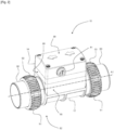
- the analysis device 10 is installed on a pipe 90 constituting a water filtration circuit of a swimming pool illustrated on the Figure 5 .
- the analysis device 10 comprises two annular flanges 91 which constitute a connection device 92 of the analysis device 10 on the pipe 90.
- Each annular flange 91 is for example provided with reliefs 93 promoting gripping of the annular flange 91 when connecting the analysis device 10 to the pipe 90.
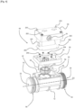
- the waterproof housing 14 comprises a base 95 secured to the analysis chamber 12 and a cover 96 which can be attached to the base 95 via a joint plane 97.
- the joint plane 97 extends for example inside a plane orthogonal to the axis of rotation A2 of the propeller 52 of the turbine 50.
- the cover 96 comprises a cover 98 and a connecting part 99, the connecting part 99 being interposed between the cover 98 and the base 95.
- the connecting part 99 is equipped with the watertight partition 16.
- the connecting part 99 delimits with the cover 98 an internal volume 200 capable of housing electrical and/or electronic components 201, in particular arranged on a electronic card 202.
- the cover 98 is attached to the connecting part 99 via first screwing means 203 or the like.
- the connecting part 99 is also attached to the base via second screwing means 204.
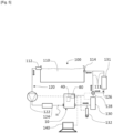
- FIG. 5 schematically shows a swimming pool 100 equipped with an analysis device 10 according to the invention.
- the swimming pool 100 comprises a basin 110 provided with a skimmer 112 (skimmer) and a filtration circuit 120 connecting the skimmer 112 to a discharge nozzle 114.
- a skimmer 112 skimmer
- a filtration circuit 120 connecting the skimmer 112 to a discharge nozzle 114.
- the filtration circuit 120 comprises, in order from the skimmer 112, a circulation pump 122, a filter 124, the analysis device 10 as described above and a water treatment unit 130.
- the device analysis 10 is placed between the filter 124 and the discharge nozzle 114.
- the different organs are interconnected by water pipes 111.
- the water pipes 111 represented symbolically, are formed of pipes and pipes. Water circulation is indicated by small arrows near the water pipes.
- the water treatment unit 130 may include, for example, a source of ultraviolet radiation, and/or an electrolysis cell.
- a branch 126 of the filtration circuit 120 includes a valve 128 and a heating unit 131 for heating the water.
- the heating unit 131 can be a boiler exchanger or a circulating solar panel, for example.
- the valve 128 is a three-way motorized valve, controlled by the analysis device 10. It allows all or part of the water to be diverted or not from the filtration circuit 120 to heat it.
- the proportion of water circulating in the diversion is controlled, for example, as a function of a water temperature established by the temperature probe 32 indicated on the figure 1 .
- a dosing pump 132 is connected to a pipe of the filtration circuit 120.
- the dosing pump 132 is configured to add, if necessary, to the water an additive intended to correct its chemical composition.
- Several dosing pumps can be installed according to the same diagram, to add several different additives.
- the reference 140 designates a remote laptop, or other comparable communications equipment, connected to the analysis device 10 via a wireless communications network, for example the Internet, or a short-range local area network. (WiFi, Bluetooth, LPWAN).
- a wireless communications network for example the Internet, or a short-range local area network. (WiFi, Bluetooth, LPWAN).
- the analysis or alert data generated by the data processor 40 of the analysis device 10 is transferred to the portable computer 140 or comparable communications equipment. They can be displayed and visualized using a dedicated graphical interface.
- the various pieces of equipment in the filtration circuit and in particular the circulation pump 122, the valve 128, the water treatment unit 130 and the dosing pump 132 receive control data from the data processor 40 of the analysis device.
- This data is also transmitted wirelessly, using the radio frequency transceiver 80 of the analysis device to a remote receiver.
- the radio link between the analysis device 10 and the various pieces of equipment in communication with the analysis device 10 is represented symbolically by mixed lines. For simplification, only the data processor 40 and the transceiver 80 of the analysis device 10 are represented on the figure 2 .
- the control data can be transmitted directly by the analysis device 10 to the various pieces of equipment in the filtration circuit 120.
- each piece of equipment has a data transceiver and an interface making it possible to control its operation in response to the data. commands developed by the data processor of the analysis device.
- the control data can also be transmitted to a control interface common to different pieces of equipment. This interface can be placed near the equipment in a technical room of the swimming pool, not shown. In the latter case, the filtration circuit equipment can be connected to the common control interface by wire.
- the control data produced by the data processor 40 may be proportional to the flow of water in the filtration circuit or may be conditioned on the existence of a flow of water in this circuit.
- the existence of a water flow or the magnitude of the water flow is measured by the signal coming from the electric generator in the manner described previously with reference to the figure 1 .
- an injection of pH correcting liquid into the water pipes is not desirable when the water is not circulating, to avoid an accumulation of potentially aggressive products for the walls of the water pipes 111.
- a command to inhibit the operation of the dosing pump 132 can be issued.
- the water analysis device 10 can be configured in the form of an insert, which can be housed, and in particular screwed, into the discharge nozzle 114 of the swimming pool.
- the water inlet 22 and the water outlet 24 of the analysis chamber 12 of the water analysis device are preferably coaxial, in the extension of one another and centered on an axis of the delivery nozzle. The water from the discharge nozzle passing through the analysis device is then used to drive the device's turbine.
- Such an embodiment allows simple installation of the water analysis device on an existing swimming pool, and, due to its autonomous nature, does not require any electrical wiring.
- the turbine 50 activates a dynamo 57 or an alternator 59 which converts the force of the movement of the water in the filtration circuit 120 into electrical energy.
- the dynamo 57 directly delivers a direct voltage while the alternator 59 supplies a three-phase voltage which must be rectified.
- the energy supplied is proportional to the speed of circulation of the water and therefore to the flow of water in the filtration circuit 120.
- the turbine 50 therefore also makes it possible to detect the absence of flow or filtration defects (clogging of the filter, clogged skimmer, clogged pump, closed valve, etc.) and to measure the flow of water passing through the analysis device 10.
- the analysis device 10 calculates the water flow as a function of an electrical voltage produced by the voltage converter 64 via the turbine 50.
- the electrical voltage supplied is proportional to the rotation speed of the turbine 50 and therefore to the flow rate of water passing through the analysis device 10..
- the latter is therefore capable of measuring the water flow rate by monitoring the voltage supplied by the voltage converter 64.
- This flow rate is crucial data for the correct operation of the swimming pool 110 and the detection or absence of flow makes it possible to know whether the circulation pump 122 is running or stopped.
- This information is used by the analysis device 10 for its own management and is transmitted to a remote receiver which takes it into account to trigger, for example, the production of chlorine or the injection of a pH correcting liquid into the circuit.
- filtration 120 It is in fact essential to ensure that the water circulates in the filtration circuit 120 to avoid a risk of accumulation of aggressive products in the filtration circuit 120.
- a speed water circulation of around 1.5 m/s to 2 m/s is ideal for good filtration. In a pipe with a diameter of 50 mm, this corresponds to a flow rate of 14 m 3 /h which allows a 56 m 3 swimming pool to be recycled four times per day.
- Clogging of the filter 124 increases resistance to flow and reduces the flow of water in the filtration circuit 120.
- the flow information transmitted to the receiver can lead to an adjustment of the filtration speed and/or be compared to a minimum threshold and trigger a washing of the filter 124 or an alert for the user.
- the electrical energy supplied by the turbine 50 is used to charge the battery 60 which makes it possible on the one hand to stabilize the voltage supplied to the data processor 40 and to ensure the operating autonomy of the analysis device even in absence of water circulation inside the filtration circuit 120. Indeed, the filtration may only operate for a few hours per day and the analysis device 10 must be able to transmit the measured values and in particular the temperature of the water during periods without filtration. Thus, the battery 60 has sufficient storage capacity to ensure the operation of the analysis device 10 in the absence of water circulation for approximately one day.
- a battery charge monitoring circuit 60 makes it possible to adjust the electrical consumption of the analysis device 10 as a function of the charge level of the battery 60.
- the device can reduce the intensity of the lighting device 86, reduce the frequency of measurements and radio transmissions, alert the user with very short light flashes, send notifications to a mobile phone type receiver.
Landscapes
- Engineering & Computer Science (AREA)
- Chemical & Material Sciences (AREA)
- Life Sciences & Earth Sciences (AREA)
- Hydrology & Water Resources (AREA)
- Environmental & Geological Engineering (AREA)
- Water Supply & Treatment (AREA)
- Organic Chemistry (AREA)
- Health & Medical Sciences (AREA)
- General Engineering & Computer Science (AREA)
- Analytical Chemistry (AREA)
- Combustion & Propulsion (AREA)
- Power Engineering (AREA)
- Food Science & Technology (AREA)
- Medicinal Chemistry (AREA)
- Physics & Mathematics (AREA)
- Mechanical Engineering (AREA)
- Biochemistry (AREA)
- General Health & Medical Sciences (AREA)
- General Physics & Mathematics (AREA)
- Immunology (AREA)
- Pathology (AREA)
- Investigating Or Analyzing Materials By The Use Of Electric Means (AREA)
- Other Liquid Machine Or Engine Such As Wave Power Use (AREA)
Claims (14)
- Vorrichtung (10) zur Analyse von Wasser, umfassend:- eine Analysekammer (12), die mit mindestens einem Wassereinlass (22) und mindestens einem Wasserauslass (24) versehen ist,- ein wasserdichtes Gehäuse (14), das an die Analysekammer (12) angrenzt und mittels einer Trennwand (16) von der Analysekammer (12) isoliert ist,- einen Datenprozessor (40), der im wasserdichten Gehäuse (14) untergebracht ist,- mindestens eine Sonde (30, 32, 33, 34, 35, 36, 37), die elektrisch mit einem Dateneingang (42) des Datenprozessors (40) verbunden ist, und sich in die Analysekammer (12) erstreckt, gekennzeichnet durch:- eine Stromversorgung (50, 56, 60, 62), die elektrisch mit einem Versorgungseingang (46) des Datenprozessors (40) verbunden ist, wobei die Stromversorgung einen elektrischen Generator (56) umfasst, der mit einer Turbine (50) ausgestattet ist, die in der Analysekammer (12) untergebracht ist, wobei der elektrische Generator (56) ein Funktionssignal einer Drehzahl der Turbine (50) liefert, und elektrisch mit dem Dateneingang (42) des Datenprozessors (40) zur Übertragung des Signals an den Datenprozessor verbunden ist, wobei die Turbine (50) mit einem Propellerrad (52) ausgestattet ist, das um sich selbst drehbar und um eine Umlaufsachse (A2) beweglich angeordnet ist, die orthogonal zu einer Drehachse (A1) der Analysekammer (12) ist, wobei die Sonde (30, 32, 33, 34, 35, 36, 37) im Innern eines Raums (23) der Analysekammer (12) untergebracht ist, der radial zwischen dem Wassereinlass (22) und der Trennwand (16) eingesetzt ist, wobei das Propellerrad (52) axial im Innern der Analysekammer (12) zwischen dem Raum (23) und dem Wasserauslass (24) aufgestellt ist.
- Analysevorrichtung nach Anspruch 1, wobei der elektrische Generator (56) einen von einem Drehstromgenerator (59) und einem Dynamo (57) umfasst.
- Analysevorrichtung nach Anspruch 2, wobei die Turbine (50) mit einer Welle (53) ausgestattet ist, die das Propellerrad (52) mit dem Dynamo (57) oder dem Drehstromgenerator (59) verbindet.
- Analysevorrichtung nach Anspruch 3, wobei die Welle (53) der Turbine (50) durch die Trennwand (16) verläuft, die die Analysekammer (12) vom wasserdichten Gehäuse (14) trennt.
- Analysevorrichtung nach Anspruch 3, wobei der elektrische Generator (56) einen Induktor (54) mit Permanentmagnet beinhaltet, der fest mit der Turbine (50) verbunden ist, und einen Anker (58), der im wasserdichten Gehäuse (14) untergebracht ist.
- Analysevorrichtung nach einem der vorhergehenden Ansprüche, wobei das Funktionssignal der Drehzahl der Turbine (50) eine Ausgangsspannung des elektrischen Generators (56) ist.
- Analysevorrichtung nach einem der vorhergehenden Ansprüche, wobei die Stromversorgung (50, 56, 60, 62) ferner einen elektrischen Energiespeicher (60) umfasst, der im Innern des wasserdichten Gehäuses (14) untergebracht ist.
- Analysevorrichtung nach einem der vorhergehenden Ansprüche, wobei der Datenprozessor (40) mit einem hertzschen Sendeempfänger (80) ausgerüstet ist, der im wasserdichten Gehäuse (14) untergebracht ist, und konfiguriert ist, um die mindestens einen von den Analysedaten, Steuerdaten und Alarmdaten zu übertragen.
- Analysevorrichtung nach einem der vorhergehenden Ansprüche, wobei der Datenprozessor (40) mit einer externen Eingabe-Ausgabe-Schnittstelle (81) ausgerüstet ist.
- Analysevorrichtung nach einem der vorhergehenden Ansprüche, wobei die Sonde (30) aus einer Temperatursonde (32), einer pH-Sonde (33), einer Oxidations-Reduktions-Potential-Sonde (34), einer Salzgehalt-Sonde (35), einer gelösten Feststoff-Sonde (36) und einer Trübungssonde (37) ausgewählt ist.
- Schwimmbad (100), einen Filterkreislauf (120) umfassend, der mit einer Umwälzpumpe (122) ausgestattet ist, und mindestens einem Filter (124), dadurch gekennzeichnet, dass der Filterkreislauf (120) ferner mit einer Analysevorrichtung (10) nach einem der vorhergehenden Ansprüche ausgestattet ist.
- Schwimmbad (100) nach Anspruch 11, wobei die Analysevorrichtung (10) stromabwärts des Filters (124) angeschlossen ist.
- Schwimmbad (100) nach einem der Ansprüche 11 und 12, wobei die Analysevorrichtung (10) in Reihe geschaltet ist mit der Umwälzpumpe (122) und dem Filter (124), wobei der Wassereinlass (22) und der Wasserauslass (24) der Analysekammer (12) mit einer Leitung (111) des Filterkreislaufs verbunden sind.
- Schwimmbad (100) nach einem der Ansprüche 11 bis 13, ferner mindestens eine Dosierpumpe (132) für Korrekturflüssigkeit umfassend.
Applications Claiming Priority (2)
| Application Number | Priority Date | Filing Date | Title |
|---|---|---|---|
| FR2003981A FR3109445B1 (fr) | 2020-04-21 | 2020-04-21 | Dispositif d’analyse d’eau autonome et piscine équipée d’un tel dispositif |
| PCT/IB2021/053252 WO2021214656A1 (fr) | 2020-04-21 | 2021-04-20 | Dispositif d'analyse d'eau autonome et piscine equipée d'un tel dispositif |
Publications (3)
| Publication Number | Publication Date |
|---|---|
| EP4139675A1 EP4139675A1 (de) | 2023-03-01 |
| EP4139675C0 EP4139675C0 (de) | 2024-06-05 |
| EP4139675B1 true EP4139675B1 (de) | 2024-06-05 |
Family
ID=70978273
Family Applications (1)
| Application Number | Title | Priority Date | Filing Date |
|---|---|---|---|
| EP21720581.4A Active EP4139675B1 (de) | 2020-04-21 | 2021-04-20 | Autonome wasseranalysevorrichtung und schwimmbad mit solch einer vorrichtung |
Country Status (4)
| Country | Link |
|---|---|
| US (1) | US12084357B2 (de) |
| EP (1) | EP4139675B1 (de) |
| FR (1) | FR3109445B1 (de) |
| WO (1) | WO2021214656A1 (de) |
Families Citing this family (1)
| Publication number | Priority date | Publication date | Assignee | Title |
|---|---|---|---|---|
| US10925804B2 (en) | 2017-10-04 | 2021-02-23 | Sundance Spas, Inc. | Remote spa control system |
Citations (1)
| Publication number | Priority date | Publication date | Assignee | Title |
|---|---|---|---|---|
| DE202009002145U1 (de) * | 2009-02-17 | 2009-06-18 | Hannack, Markus | Stromerzeuger für eine Wasserleitung |
Family Cites Families (7)
| Publication number | Priority date | Publication date | Assignee | Title |
|---|---|---|---|---|
| US20100250449A1 (en) | 2004-10-26 | 2010-09-30 | Kevin Doyle | Inline chlorinator with integral control package, heat dissipation and warranty information accumulator |
| CA2974938A1 (en) * | 2014-08-11 | 2016-02-18 | Formarum Inc. | Water treatment system and method |
| WO2016183666A1 (en) * | 2015-05-19 | 2016-11-24 | Formarum Inc. | Water treatment system and method |
| US20170291141A1 (en) * | 2016-04-07 | 2017-10-12 | My Aqueduct, LLC | Portable water collection and filtration system |
| US10221853B2 (en) * | 2016-05-01 | 2019-03-05 | Sucxess LLC | Fluid circulation monitoring system |
| US11427484B1 (en) * | 2017-08-15 | 2022-08-30 | Aquacal Autopilot, Inc. | Salt water chlorine generator having an integral multifunctional flow sensor |
| US11795717B2 (en) * | 2020-04-20 | 2023-10-24 | Rheem Manufacturing Company | Fluid chemistry manifolds and systems |
-
2020
- 2020-04-21 FR FR2003981A patent/FR3109445B1/fr active Active
-
2021
- 2021-04-20 US US17/996,490 patent/US12084357B2/en active Active
- 2021-04-20 EP EP21720581.4A patent/EP4139675B1/de active Active
- 2021-04-20 WO PCT/IB2021/053252 patent/WO2021214656A1/fr not_active Ceased
Patent Citations (1)
| Publication number | Priority date | Publication date | Assignee | Title |
|---|---|---|---|---|
| DE202009002145U1 (de) * | 2009-02-17 | 2009-06-18 | Hannack, Markus | Stromerzeuger für eine Wasserleitung |
Non-Patent Citations (1)
| Title |
|---|
| HOFFMANN D ET AL: "Energy Harvesting from Fluid Flow in Water Pipelines for Smart Metering Applications", JOURNAL OF PHYSICS: CONFERENCE SERIES, INSTITUTE OF PHYSICS PUBLISHING, BRISTOL, GB, vol. 476, no. 1, 4 December 2013 (2013-12-04), pages 12104, XP020254816, ISSN: 1742-6596, [retrieved on 20131204], DOI: 10.1088/1742-6596/476/1/012104 * |
Also Published As
| Publication number | Publication date |
|---|---|
| FR3109445A1 (fr) | 2021-10-22 |
| FR3109445B1 (fr) | 2023-12-01 |
| US12084357B2 (en) | 2024-09-10 |
| WO2021214656A1 (fr) | 2021-10-28 |
| EP4139675C0 (de) | 2024-06-05 |
| US20230219828A1 (en) | 2023-07-13 |
| EP4139675A1 (de) | 2023-03-01 |
Similar Documents
| Publication | Publication Date | Title |
|---|---|---|
| US11187223B2 (en) | Home flood prevention appliance system | |
| US10934184B2 (en) | Systems and methods for sanitizing pool and spa water | |
| EP0820344B1 (de) | Verfahren zum betreiben und steuern einer gruppe von filtrationsmembranemodulen und eine gruppe von modulen zur ausfürung dieses verfahrens | |
| US9897563B2 (en) | Amperometric sensor system | |
| FR3076918A1 (fr) | Dispositif de regulation thermostatique instrumente et robinet mitigeur comprenant un tel dispositif de regulation thermostatique | |
| WO2011004015A2 (fr) | Gestion d'un parc de piscines | |
| EP3012499B1 (de) | Verfahren zur überwachung der wasserverteilung, und entsprechende wasserverteilungsvorrichtung | |
| FR2943696A1 (fr) | Installation et procede de controle de la qualite de l'eau dans un reseau d'eau potable | |
| CN101135312A (zh) | 用于包含悬浮物的水体的水泵 | |
| EP4139675A1 (de) | Autonome wasseranalysevorrichtung und schwimmbad mit solch einer vorrichtung | |
| JP2011094368A (ja) | 受水槽監視システム | |
| FR3108414A1 (fr) | Dispositif instrumenté pour un robinet mitigeur, ainsi que robinet mitigeur comprenant un tel dispositif instrumenté | |
| FR2947906A1 (fr) | Controle de la qualite de l'eau dans une piscine individuelle | |
| FR2461254A1 (fr) | Installation de mesure de la qualite d'une eau douce ou saumatre a nettoyage integre | |
| FR2682673A1 (fr) | Generateur electrolytique d'hypochlorite de sodium pour le traitement de l'eau. | |
| FR3003339A1 (fr) | Procede pour le recyclage et le chauffage d'eau sanitaire au moyen d'un dispositif de recirculation et de chauffage | |
| FR2704872A1 (fr) | Dispositif producteur d'hypochlorite de sodium pour la désinfection de l'eau en particulier l'eau de piscine. | |
| EP4242399B1 (de) | Wasserabgabevorrichtung zur wartung eines künstlichen beckens | |
| EP4172488B1 (de) | Hydroelektrische anlage für ein wassernetz und wassernetz mit einer solchen anlage | |
| US20240310349A1 (en) | Water meter and associated water system using the same | |
| FR3152802A1 (fr) | Dispositif de traitement automatique de l’eau d’un bassin par chloration liquide | |
| FR2764321A1 (fr) | Procede d'entretien de l'eau d'une piscine et dispositif pour la mise en oeuvre du procede | |
| WO2023011863A1 (fr) | Dispositif de generation de vapeur | |
| EP3947294A1 (de) | System zur verbesserung und verteilung von wasser | |
| AU2005100965A4 (en) | Pump Safe (Allocated application number 2004906800) |
Legal Events
| Date | Code | Title | Description |
|---|---|---|---|
| STAA | Information on the status of an ep patent application or granted ep patent |
Free format text: STATUS: UNKNOWN |
|
| STAA | Information on the status of an ep patent application or granted ep patent |
Free format text: STATUS: THE INTERNATIONAL PUBLICATION HAS BEEN MADE |
|
| PUAI | Public reference made under article 153(3) epc to a published international application that has entered the european phase |
Free format text: ORIGINAL CODE: 0009012 |
|
| STAA | Information on the status of an ep patent application or granted ep patent |
Free format text: STATUS: REQUEST FOR EXAMINATION WAS MADE |
|
| 17P | Request for examination filed |
Effective date: 20221017 |
|
| AK | Designated contracting states |
Kind code of ref document: A1 Designated state(s): AL AT BE BG CH CY CZ DE DK EE ES FI FR GB GR HR HU IE IS IT LI LT LU LV MC MK MT NL NO PL PT RO RS SE SI SK SM TR |
|
| DAV | Request for validation of the european patent (deleted) | ||
| DAX | Request for extension of the european patent (deleted) | ||
| GRAP | Despatch of communication of intention to grant a patent |
Free format text: ORIGINAL CODE: EPIDOSNIGR1 |
|
| STAA | Information on the status of an ep patent application or granted ep patent |
Free format text: STATUS: GRANT OF PATENT IS INTENDED |
|
| RIC1 | Information provided on ipc code assigned before grant |
Ipc: C02F 103/42 20060101ALN20231108BHEP Ipc: C02F 1/66 20230101ALN20231108BHEP Ipc: C02F 1/46 20230101ALN20231108BHEP Ipc: C02F 1/32 20230101ALN20231108BHEP Ipc: C02F 1/00 20230101ALI20231108BHEP Ipc: F03B 17/06 20060101ALI20231108BHEP Ipc: G01N 33/18 20060101AFI20231108BHEP |
|
| RIC1 | Information provided on ipc code assigned before grant |
Ipc: C02F 103/42 20060101ALN20231116BHEP Ipc: C02F 1/66 20230101ALN20231116BHEP Ipc: C02F 1/46 20230101ALN20231116BHEP Ipc: C02F 1/32 20230101ALN20231116BHEP Ipc: C02F 1/00 20230101ALI20231116BHEP Ipc: F03B 17/06 20060101ALI20231116BHEP Ipc: G01N 33/18 20060101AFI20231116BHEP |
|
| INTG | Intention to grant announced |
Effective date: 20231130 |
|
| RAP3 | Party data changed (applicant data changed or rights of an application transferred) |
Owner name: BLEU ELECTRIQUE |
|
| GRAS | Grant fee paid |
Free format text: ORIGINAL CODE: EPIDOSNIGR3 |
|
| GRAA | (expected) grant |
Free format text: ORIGINAL CODE: 0009210 |
|
| STAA | Information on the status of an ep patent application or granted ep patent |
Free format text: STATUS: THE PATENT HAS BEEN GRANTED |
|
| AK | Designated contracting states |
Kind code of ref document: B1 Designated state(s): AL AT BE BG CH CY CZ DE DK EE ES FI FR GB GR HR HU IE IS IT LI LT LU LV MC MK MT NL NO PL PT RO RS SE SI SK SM TR |
|
| REG | Reference to a national code |
Ref country code: CH Ref legal event code: EP |
|
| REG | Reference to a national code |
Ref country code: DE Ref legal event code: R096 Ref document number: 602021014095 Country of ref document: DE |
|
| REG | Reference to a national code |
Ref country code: IE Ref legal event code: FG4D Free format text: LANGUAGE OF EP DOCUMENT: FRENCH |
|
| U01 | Request for unitary effect filed |
Effective date: 20240624 |
|
| U07 | Unitary effect registered |
Designated state(s): AT BE BG DE DK EE FI FR IT LT LU LV MT NL PT SE SI Effective date: 20240628 |
|
| PG25 | Lapsed in a contracting state [announced via postgrant information from national office to epo] |
Ref country code: HR Free format text: LAPSE BECAUSE OF FAILURE TO SUBMIT A TRANSLATION OF THE DESCRIPTION OR TO PAY THE FEE WITHIN THE PRESCRIBED TIME-LIMIT Effective date: 20240605 |
|
| PG25 | Lapsed in a contracting state [announced via postgrant information from national office to epo] |
Ref country code: GR Free format text: LAPSE BECAUSE OF FAILURE TO SUBMIT A TRANSLATION OF THE DESCRIPTION OR TO PAY THE FEE WITHIN THE PRESCRIBED TIME-LIMIT Effective date: 20240906 |
|
| PG25 | Lapsed in a contracting state [announced via postgrant information from national office to epo] |
Ref country code: ES Free format text: LAPSE BECAUSE OF FAILURE TO SUBMIT A TRANSLATION OF THE DESCRIPTION OR TO PAY THE FEE WITHIN THE PRESCRIBED TIME-LIMIT Effective date: 20240605 |
|
| PG25 | Lapsed in a contracting state [announced via postgrant information from national office to epo] |
Ref country code: NO Free format text: LAPSE BECAUSE OF FAILURE TO SUBMIT A TRANSLATION OF THE DESCRIPTION OR TO PAY THE FEE WITHIN THE PRESCRIBED TIME-LIMIT Effective date: 20240905 Ref country code: HR Free format text: LAPSE BECAUSE OF FAILURE TO SUBMIT A TRANSLATION OF THE DESCRIPTION OR TO PAY THE FEE WITHIN THE PRESCRIBED TIME-LIMIT Effective date: 20240605 Ref country code: GR Free format text: LAPSE BECAUSE OF FAILURE TO SUBMIT A TRANSLATION OF THE DESCRIPTION OR TO PAY THE FEE WITHIN THE PRESCRIBED TIME-LIMIT Effective date: 20240906 Ref country code: ES Free format text: LAPSE BECAUSE OF FAILURE TO SUBMIT A TRANSLATION OF THE DESCRIPTION OR TO PAY THE FEE WITHIN THE PRESCRIBED TIME-LIMIT Effective date: 20240605 Ref country code: RS Free format text: LAPSE BECAUSE OF FAILURE TO SUBMIT A TRANSLATION OF THE DESCRIPTION OR TO PAY THE FEE WITHIN THE PRESCRIBED TIME-LIMIT Effective date: 20240905 |
|
| PG25 | Lapsed in a contracting state [announced via postgrant information from national office to epo] |
Ref country code: PL Free format text: LAPSE BECAUSE OF FAILURE TO SUBMIT A TRANSLATION OF THE DESCRIPTION OR TO PAY THE FEE WITHIN THE PRESCRIBED TIME-LIMIT Effective date: 20240605 |
|
| PG25 | Lapsed in a contracting state [announced via postgrant information from national office to epo] |
Ref country code: IS Free format text: LAPSE BECAUSE OF FAILURE TO SUBMIT A TRANSLATION OF THE DESCRIPTION OR TO PAY THE FEE WITHIN THE PRESCRIBED TIME-LIMIT Effective date: 20241005 |
|
| PG25 | Lapsed in a contracting state [announced via postgrant information from national office to epo] |
Ref country code: CZ Free format text: LAPSE BECAUSE OF FAILURE TO SUBMIT A TRANSLATION OF THE DESCRIPTION OR TO PAY THE FEE WITHIN THE PRESCRIBED TIME-LIMIT Effective date: 20240605 |
|
| PG25 | Lapsed in a contracting state [announced via postgrant information from national office to epo] |
Ref country code: RO Free format text: LAPSE BECAUSE OF FAILURE TO SUBMIT A TRANSLATION OF THE DESCRIPTION OR TO PAY THE FEE WITHIN THE PRESCRIBED TIME-LIMIT Effective date: 20240605 Ref country code: SK Free format text: LAPSE BECAUSE OF FAILURE TO SUBMIT A TRANSLATION OF THE DESCRIPTION OR TO PAY THE FEE WITHIN THE PRESCRIBED TIME-LIMIT Effective date: 20240605 |
|
| PG25 | Lapsed in a contracting state [announced via postgrant information from national office to epo] |
Ref country code: SM Free format text: LAPSE BECAUSE OF FAILURE TO SUBMIT A TRANSLATION OF THE DESCRIPTION OR TO PAY THE FEE WITHIN THE PRESCRIBED TIME-LIMIT Effective date: 20240605 |
|
| PG25 | Lapsed in a contracting state [announced via postgrant information from national office to epo] |
Ref country code: SM Free format text: LAPSE BECAUSE OF FAILURE TO SUBMIT A TRANSLATION OF THE DESCRIPTION OR TO PAY THE FEE WITHIN THE PRESCRIBED TIME-LIMIT Effective date: 20240605 Ref country code: SK Free format text: LAPSE BECAUSE OF FAILURE TO SUBMIT A TRANSLATION OF THE DESCRIPTION OR TO PAY THE FEE WITHIN THE PRESCRIBED TIME-LIMIT Effective date: 20240605 Ref country code: RO Free format text: LAPSE BECAUSE OF FAILURE TO SUBMIT A TRANSLATION OF THE DESCRIPTION OR TO PAY THE FEE WITHIN THE PRESCRIBED TIME-LIMIT Effective date: 20240605 Ref country code: PL Free format text: LAPSE BECAUSE OF FAILURE TO SUBMIT A TRANSLATION OF THE DESCRIPTION OR TO PAY THE FEE WITHIN THE PRESCRIBED TIME-LIMIT Effective date: 20240605 Ref country code: IS Free format text: LAPSE BECAUSE OF FAILURE TO SUBMIT A TRANSLATION OF THE DESCRIPTION OR TO PAY THE FEE WITHIN THE PRESCRIBED TIME-LIMIT Effective date: 20241005 Ref country code: CZ Free format text: LAPSE BECAUSE OF FAILURE TO SUBMIT A TRANSLATION OF THE DESCRIPTION OR TO PAY THE FEE WITHIN THE PRESCRIBED TIME-LIMIT Effective date: 20240605 |
|
| U20 | Renewal fee for the european patent with unitary effect paid |
Year of fee payment: 5 Effective date: 20250203 |
|
| PLBE | No opposition filed within time limit |
Free format text: ORIGINAL CODE: 0009261 |
|
| STAA | Information on the status of an ep patent application or granted ep patent |
Free format text: STATUS: NO OPPOSITION FILED WITHIN TIME LIMIT |
|
| 26N | No opposition filed |
Effective date: 20250306 |
|
| REG | Reference to a national code |
Ref country code: CH Ref legal event code: H13 Free format text: ST27 STATUS EVENT CODE: U-0-0-H10-H13 (AS PROVIDED BY THE NATIONAL OFFICE) Effective date: 20251125 |
|
| PG25 | Lapsed in a contracting state [announced via postgrant information from national office to epo] |
Ref country code: MC Free format text: LAPSE BECAUSE OF FAILURE TO SUBMIT A TRANSLATION OF THE DESCRIPTION OR TO PAY THE FEE WITHIN THE PRESCRIBED TIME-LIMIT Effective date: 20240605 |
|
| GBPC | Gb: european patent ceased through non-payment of renewal fee |
Effective date: 20250420 |
|
| PG25 | Lapsed in a contracting state [announced via postgrant information from national office to epo] |
Ref country code: GB Free format text: LAPSE BECAUSE OF NON-PAYMENT OF DUE FEES Effective date: 20250420 |
|
| PG25 | Lapsed in a contracting state [announced via postgrant information from national office to epo] |
Ref country code: CH Free format text: LAPSE BECAUSE OF NON-PAYMENT OF DUE FEES Effective date: 20250430 |
|
| U20 | Renewal fee for the european patent with unitary effect paid |
Year of fee payment: 6 Effective date: 20260219 |
|
| PG25 | Lapsed in a contracting state [announced via postgrant information from national office to epo] |
Ref country code: IE Free format text: LAPSE BECAUSE OF NON-PAYMENT OF DUE FEES Effective date: 20250420 |
|
| PG25 | Lapsed in a contracting state [announced via postgrant information from national office to epo] |
Ref country code: CY Free format text: LAPSE BECAUSE OF FAILURE TO SUBMIT A TRANSLATION OF THE DESCRIPTION OR TO PAY THE FEE WITHIN THE PRESCRIBED TIME-LIMIT Effective date: 20240605 |