EP4139763B1 - Procédé et système pour déterminer l'emplacement d'un boîtier de drone en vue d'un atterrissage et d'un chargement stabilisés d'un drone - Google Patents
Procédé et système pour déterminer l'emplacement d'un boîtier de drone en vue d'un atterrissage et d'un chargement stabilisés d'un drone Download PDFInfo
- Publication number
- EP4139763B1 EP4139763B1 EP21922735.2A EP21922735A EP4139763B1 EP 4139763 B1 EP4139763 B1 EP 4139763B1 EP 21922735 A EP21922735 A EP 21922735A EP 4139763 B1 EP4139763 B1 EP 4139763B1
- Authority
- EP
- European Patent Office
- Prior art keywords
- drone
- charging
- landing
- platform
- sensing circuit
- Prior art date
- Legal status (The legal status is an assumption and is not a legal conclusion. Google has not performed a legal analysis and makes no representation as to the accuracy of the status listed.)
- Active
Links
Images



Classifications
-
- B—PERFORMING OPERATIONS; TRANSPORTING
- B64—AIRCRAFT; AVIATION; COSMONAUTICS
- B64U—UNMANNED AERIAL VEHICLES [UAV]; EQUIPMENT THEREFOR
- B64U70/00—Launching, take-off or landing arrangements
- B64U70/80—Vertical take-off or landing, e.g. using rockets
-
- B—PERFORMING OPERATIONS; TRANSPORTING
- B60—VEHICLES IN GENERAL
- B60L—PROPULSION OF ELECTRICALLY-PROPELLED VEHICLES; SUPPLYING ELECTRIC POWER FOR AUXILIARY EQUIPMENT OF ELECTRICALLY-PROPELLED VEHICLES; ELECTRODYNAMIC BRAKE SYSTEMS FOR VEHICLES IN GENERAL; MAGNETIC SUSPENSION OR LEVITATION FOR VEHICLES; MONITORING OPERATING VARIABLES OF ELECTRICALLY-PROPELLED VEHICLES; ELECTRIC SAFETY DEVICES FOR ELECTRICALLY-PROPELLED VEHICLES
- B60L53/00—Methods of charging batteries, specially adapted for electric vehicles; Charging stations or on-board charging equipment therefor; Exchange of energy storage elements in electric vehicles
- B60L53/10—Methods of charging batteries, specially adapted for electric vehicles; Charging stations or on-board charging equipment therefor; Exchange of energy storage elements in electric vehicles characterised by the energy transfer between the charging station and the vehicle
- B60L53/14—Conductive energy transfer
-
- B—PERFORMING OPERATIONS; TRANSPORTING
- B64—AIRCRAFT; AVIATION; COSMONAUTICS
- B64U—UNMANNED AERIAL VEHICLES [UAV]; EQUIPMENT THEREFOR
- B64U70/00—Launching, take-off or landing arrangements
- B64U70/90—Launching from or landing on platforms
-
- B—PERFORMING OPERATIONS; TRANSPORTING
- B64—AIRCRAFT; AVIATION; COSMONAUTICS
- B64U—UNMANNED AERIAL VEHICLES [UAV]; EQUIPMENT THEREFOR
- B64U80/00—Transport or storage specially adapted for UAVs
- B64U80/20—Transport or storage specially adapted for UAVs with arrangements for servicing the UAV
- B64U80/25—Transport or storage specially adapted for UAVs with arrangements for servicing the UAV for recharging batteries; for refuelling
-
- B—PERFORMING OPERATIONS; TRANSPORTING
- B64—AIRCRAFT; AVIATION; COSMONAUTICS
- B64U—UNMANNED AERIAL VEHICLES [UAV]; EQUIPMENT THEREFOR
- B64U80/00—Transport or storage specially adapted for UAVs
- B64U80/40—Transport or storage specially adapted for UAVs for two or more UAVs
-
- B—PERFORMING OPERATIONS; TRANSPORTING
- B60—VEHICLES IN GENERAL
- B60L—PROPULSION OF ELECTRICALLY-PROPELLED VEHICLES; SUPPLYING ELECTRIC POWER FOR AUXILIARY EQUIPMENT OF ELECTRICALLY-PROPELLED VEHICLES; ELECTRODYNAMIC BRAKE SYSTEMS FOR VEHICLES IN GENERAL; MAGNETIC SUSPENSION OR LEVITATION FOR VEHICLES; MONITORING OPERATING VARIABLES OF ELECTRICALLY-PROPELLED VEHICLES; ELECTRIC SAFETY DEVICES FOR ELECTRICALLY-PROPELLED VEHICLES
- B60L2200/00—Type of vehicles
- B60L2200/10—Air crafts
-
- B—PERFORMING OPERATIONS; TRANSPORTING
- B64—AIRCRAFT; AVIATION; COSMONAUTICS
- B64U—UNMANNED AERIAL VEHICLES [UAV]; EQUIPMENT THEREFOR
- B64U10/00—Type of UAV
- B64U10/10—Rotorcrafts
- B64U10/13—Flying platforms
- B64U10/14—Flying platforms with four distinct rotor axes, e.g. quadcopters
-
- B—PERFORMING OPERATIONS; TRANSPORTING
- B64—AIRCRAFT; AVIATION; COSMONAUTICS
- B64U—UNMANNED AERIAL VEHICLES [UAV]; EQUIPMENT THEREFOR
- B64U2201/00—UAVs characterised by their flight controls
- B64U2201/10—UAVs characterised by their flight controls autonomous, i.e. by navigating independently from ground or air stations, e.g. by using inertial navigation systems [INS]
-
- Y—GENERAL TAGGING OF NEW TECHNOLOGICAL DEVELOPMENTS; GENERAL TAGGING OF CROSS-SECTIONAL TECHNOLOGIES SPANNING OVER SEVERAL SECTIONS OF THE IPC; TECHNICAL SUBJECTS COVERED BY FORMER USPC CROSS-REFERENCE ART COLLECTIONS [XRACs] AND DIGESTS
- Y02—TECHNOLOGIES OR APPLICATIONS FOR MITIGATION OR ADAPTATION AGAINST CLIMATE CHANGE
- Y02T—CLIMATE CHANGE MITIGATION TECHNOLOGIES RELATED TO TRANSPORTATION
- Y02T10/00—Road transport of goods or passengers
- Y02T10/60—Other road transportation technologies with climate change mitigation effect
- Y02T10/70—Energy storage systems for electromobility, e.g. batteries
-
- Y—GENERAL TAGGING OF NEW TECHNOLOGICAL DEVELOPMENTS; GENERAL TAGGING OF CROSS-SECTIONAL TECHNOLOGIES SPANNING OVER SEVERAL SECTIONS OF THE IPC; TECHNICAL SUBJECTS COVERED BY FORMER USPC CROSS-REFERENCE ART COLLECTIONS [XRACs] AND DIGESTS
- Y02—TECHNOLOGIES OR APPLICATIONS FOR MITIGATION OR ADAPTATION AGAINST CLIMATE CHANGE
- Y02T—CLIMATE CHANGE MITIGATION TECHNOLOGIES RELATED TO TRANSPORTATION
- Y02T10/00—Road transport of goods or passengers
- Y02T10/60—Other road transportation technologies with climate change mitigation effect
- Y02T10/7072—Electromobility specific charging systems or methods for batteries, ultracapacitors, supercapacitors or double-layer capacitors
Definitions
- the present invention comprises an improvement in, and a modification of, the invention claimed in the specification of the main patent application No. 202021020842 .
- the present invention relates to unmanned aerial vehicles which are commonly known as drones, particularly to autonomous aerial vehicles, and more particularly to landing and charging of autonomous aerial vehicles or drones on charging platforms or landing platforms.
- Drones the unmanned aerial vehicles are increasingly getting involved in functions of modern life. Initial drones were assisted in take-off and landing however they are rapidly becoming technologically advanced in terms of managing newer functions of self-management. Unassisted landing of unmanned aerial vehicles now plays a vital role in autonomous as well as semi-autonomous devices. Such landing may be complex in environment with weak or no navigational signals. It is a further challenge to land on moving platforms. A precision landing paves way for further activities like charging batteries of drone, protected parking and safety of attachments from environment and attack.
- US2016/336772 A1 teaches a charging apparatus for electrically charging rechargeable battery cells of a mobile consumer including an unmanned aviation vehicle like drone.
- the charging apparatus comprises a plurality of area-wise distributed charger contacts which are insulated against each other, and are connectable with at least two consumer contacts.
- the charger contacts are connected with a control unit and electrical switches for wiring into a right polarity.
- the charger contacts are rectangle, triangle, square of hexagon shaped.
- EP3738891 A1 discloses a landing platform for unmanned aerial vehicles, UAV, having an electrical charging system that comprises a plurality of coplanar adjacent electroconductive plates, with their adjacent edges electrically insulated, the electroconductive plates being arranged on an electrically insulated support, with each electroconductive plate being connected with at least an electroconductive cable to a control unit and to a power source, configured to at least detect a change of an electric potential of an electrical circuit due to a UAV, landing on the platform and providing at least two points of contact by making electrical contact of the UAV with at least two different electroconductive plates.
- the platform is made up of a plurality of unitary modules coupled together, with each unitary module comprising an electroconductive plate, the unitary modules being adjacent and coplanar to one another.
- EP2858207 A1 discloses a method of recharging a rechargeable battery of an aircraft using a recharging station comprising a parking surface disposed for the aircraft to park thereon, the parking surface comprising conductive tiles and the rechargeable battery is connected to a positive recharging terminal and to a negative recharging terminal that are both arranged to be in contact with one or more of the conductive tiles, the method comprising determining the configuration of the aircraft on the parking surface by repeatedly connecting pairs of the tiles to an electrical power supply of the recharging station to provide a positive tile and a negative tile and testing an electrical circuit condition of the circuit connected to the power supply until the correct circuit condition is determined.
- WO2020/019109 A1 discloses a landing platform for mounting a UAV on an object, the landing platform includes a base with a landing surface; a movable cover coupled to the base to close the internal space of the landing platform; at least three visual indicators coupled to the base; a plurality of charging contacts disposed on the landing surface to make direct contact with the charging contacts of the UAV when the UAV is resting on the landing surface; and a motion compensation mechanism coupled to the landing surface to compensate for movement of the landing surface relative to the object, wherein the motion compensation mechanism provides a degree of freedom of tilting motion relative to the object along at least one axis so Keeping the level of the landing plane has nothing to do with the object.
- US2019/023133 A1 discloses a landing pad for aerial vehicles comprising a housing; a power terminal configured to draw electric power from a power source; and an electrically conductive landing terminal dorsal to the housing and configured such that, during a landing state of an aerial vehicle, the landing terminal makes contact with a plurality of electric contacts disposed ventrally to a fuselage of the aerial vehicle, and wherein the landing terminal is configured to transfer electric power drawn by the power terminal to the aerial vehicle via the electric contacts during the landing state of the aerial vehicle.
- the electrically conductive landing terminal of the landing pad comprises a plurality of nodes and a non-conductive space disposed between the plurality of nodes, wherein the plurality of nodes comprise a first set of nodes and a second set of nodes, wherein an average voltage difference between the first set of nodes and the second set of nodes is greater than zero, and wherein the first set of nodes, the second set of nodes, and the non-conductive space are disposed on a top surface of the landing terminal.
- US10479528 B1 teaches a distributed parking system for drones comprising a network of parking pads for drones distributed over a geographic area, each of which comprising a parking surface of one or more parking spots on which a drone can land and park securely, a power refill module that replenish the power source of a parked drone, a control module that controls functions of the parking pad, and a communication module through which the control module is connected to a communication network; a master controller that controls functions of the parking pads and communicates commands to and receives reports from the parking pads through the communication network; a protective box that, under the control of the control module, opens to allow a drone to land and park on the parking surface, and closes to prevent access of a drone; and an authentication module in each parking pad that authenticates an approaching drone wherein the control module opens a closed protective box to allow the approaching drone to land and park after the control module receives a message from the authentication module that the approaching drone's identity is authenticated and the drone is allowed to land and park at the parking pad.
- the distributed parking system
- CN205811623 U s a utility model which relates to a kind of contact based automatic charge device for unmanned plane, including a recharging base and a charging panel provided on a hoistable platform. It is provided with a charge controller in aid recharging base. Some pieces of charging lumps cover the charging panel, and every piece of charging lump is connected with charge controller respectively, unmanned plane's leg is provided with the first charging inlet and the second charging inlet, the first charging inlet and the second charging inlet are covered from different charging lumps with insulation in-between, thus obviate the unmanned plane from a need of artificial unloading to change battery in low-voltage state, and continue the mission and operations.
- the utility model states simple construction, with low cost.
- CN108725820 A discloses a kind of unmanned plane automatic charging platforms, related to unmanned plane charging technique field.
- the charging plane is divided into multiple " charge point " arrays by the unmanned plane automatic charging platform, each the positive-negative polarity of " charge point " can be by circuit control, the mounting anode and cathode contact below aircraft tripod.
- After aircraft is placed in charging plane detects which " charge point " is connected with the contact of aircraft tripod by certain method, then by the positive-negative polarity of these contacts of circuit control, to establish charging path.
- an unmanned aerial vehicle for transporting a payload.
- the UAV comprises a body and one or more propellers rotatably connected to the body.
- the UAV further comprises a battery mounted to the body.
- the battery is releasable from the bottom of the UAV.
- the UAV further comprises a payload container mounted to the body.
- the payload container is releasable from the bottom of the UAV to a landing platform associated with a UAV station.
- a method for transporting a payload comprising receiving a battery from an exchange station, wherein the battery is received through a landing platform associated with the exchange station; mounting the battery to the body of the UAV; upon receiving the battery, receiving a payload container from the exchange station, wherein the payload container is received through the landing platform associated with the exchange station; mounting the payload container to the body of the UAV; receiving instructions for transporting the payload container to a destination; and transporting the payload container to the destination according to the instructions.
- An objective is to invent a landing station for an unmanned aerial vehicle. Another objective is to charge batteries of landed drone(s).
- Yet another objective is to invent a method of coordination between an unmanned aerial vehicle and a corresponding landing station.
- Yet another objective is to invent a system of landing and un-assisted charging an unmanned aerial vehicle on a corresponding landing station.
- Yet another objective is to ensure minimal human and animal hazard by the landing station.
- Yet another objective is to prevent improper take-off from the landing station.
- Yet another objective is to manage contamination on landing station.
- Yet another objective is to manage inappropriate landing and unstable landing.
- the present invention is a system of unmanned aviation vehicles according to the appended claims.
- Each drone box has a drone platform.
- the drone platform has a plurality of limiting boundaries.
- the drone platform is divided into number of sensor zones.
- Each drone has a plurality of ground interfaces.
- the ground interfaces facilitate landing, parking and or charging corresponding drone.
- Each ground interface has a charging terminal at a far end.
- Each charging terminal has an interlocked switchable electricity polarity namely POSITIVE (+ve) or NEGATIVE (-ve) or NEUTRAL (N).
- the interlocked switchable polarity is switched by a Programmable Controller situated in the drone. Every landing drone has a default polarity of positive (+ve) and negative (-ve) on its two charging terminals.
- the sensor zones (111) sense the default polarity of Positive(+ve) and Negative (-ve) of the ground interfaces of the first drone and corresponding sensor zones are activated with matching polarity to commence charging of batteries of the drone. More than one sensor zone detecting identical polarity are activated as a variation.
- the identification coordinates of the activated sensor zones are communicable to a second drone so that the second drone knows where NOT to land on the drone box. Such communication enables a third and subsequent drone to ascertain whether the identified drone box is suitable and available for landing.
- the charging terminals of the plurality of ground interfaces of the drone do not generally touch down the drone platform at an identical instant. Further, ground interfaces bearing the charging terminals tend to bounce up few to several times after respective touch down. Wind and ground level may cause the ground interfaces to drag and skid on few to several sensor zones of the drone platform.
- Such a short time or transient situation is termed as the unstable situation resulting in the unstable landing.
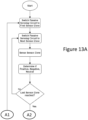
- the sensor zones sense the default polarity of Positive (+ve) and Negative (-ve) of the corresponding ground interfaces of the first drone. Additionally, a passive sensing circuit looks for a touchdown signal of all the ground interface of the drone and prevents activation of any sensor zone to commence the charging till all the ground interfaces are detected as touched down and healthy and for a minimum prescribed time which may be several milliseconds to several seconds. Thereafter, the corresponding sensor zones are activated with matching polarity to commence charging of batteries of the drone.
- the passive sensing circuit looking for a touchdown signal of all the ground interface of the drone does not detect all touch down signals for the minimum prescribed time, then it is likely that something is present between the corresponding ground interface and the sensor zone of the drone. This is diagnosed as an inappropriate landing and the drone is prevented from taking off, thereby avoiding a potential crash.
- the sensor zones detect and differentiate between presence of the ground interface and any other presence including human touch, animal touch, foreign matter and or contamination and a combination thereof by a plurality of sensors and load cells. Any sensor zone detecting presence of nothing or anything other than a ground interface remains inactivated or potential free, thus safe.
- the passive sensing circuit alternately and periodically develops a positive cycle loop when the sensor zones in contact with the ground interface of a positive terminal or dual polarity of the drone and the passive sensing circuit then develops a negative potential cycle loop when the sensor zones are in contact with the ground interface of negative terminal or dual polarity of the drone.
- this negative and positive cycle loop is passed to a signal conditioning unit which informs the decision-making processor where the positive, negative or dual-polarity ground interfaces of the drone have landed.
- the decision-making processor selects and allocates the required sensor zones for position sensed charging.
- the passive sensing circuit periodically runs the sensing cycle to continuously sense the state of the drone platform and determine presence of drone and or any object; and in a suspicious condition the drone platform remains in an inactive state, thus safe and free from hazards.
- the charging stops immediately and restarts only when suspicious conditions disappear for the minimum prescribed time.
- the detection of contamination by the passive sensing circuit on the drone platform is a significant safety aspect.
- the contamination may happen before/after and or during the charging.
- the passive sensing circuit is calibrated for a no-charging contamination as well as a while-charging contamination situation.
- the passive sensing circuit is also calibrated for contamination detection even when the drone is not present on the drone platform.
- While charging is in process with single and/or multiple drones if water spillage or rainwater contamination is detected on one or more sensor zones then the passive sensing circuit re-runs the complete sensing positive cycle loops and the negative cycle loops, re-determines the safe landing position of the single and/or multiple drones and resumes the charging safely.
- the drone as well as the drone box are individually an autonomous system with an overlapping emergency switching back up.
- the Drone Box provides the overlapping emergency switching back up to turn on and off the drone.
- the drone box first senses that the drone has landed safely, before sending a signal to turn off the drone. If the drone box gets a command from the user to turn off the drone which hasn't yet landed safely then such a command from the user shall not be executed.
- the present invention is a system comprising one or more drone box (100) and one or more drones (10).
- the drone box (100) and the drone (10) mutually communicate through a proprietary network or through GPS, WIFI and or commercially available networks.
- Figure 1 .
- Each drone box (100) has a drone platform (110).
- the drone platform (110) has a plurality of limiting boundaries (113).
- the limiting boundaries (113) are created optically, magnetically or such non-physical means that senses if any physical object is obstructing a line-of-sight radiation (122) of a source transmitter (120) and a source receiver (121).
- the source transmitter (121) and the source receiver (121) are disposed along the limiting boundaries (113).
- the drone platform (110) is divided into number of sensor zones (111).
- the sensor zones (111) are mechanically contiguous and electrically separated by an insulated separator (114) of insulation width (115).
- Each sensor zone (111) has an identification coordinate.
- the drone box (100) has a plurality of platform covers (112).
- the platform covers (112) are auto operable after meeting prescribed safety criterion for the plurality of drones (10).
- each drone (10) has a plurality of ground interfaces (11).
- the ground interfaces (11) facilitate landing, parking and or charging corresponding drone (10).
- Each ground interface (11) of each drone (10) has a unique address code.
- Each ground interface (11) has a charging terminal (13) at a far end (12).
- Each charging terminal (13) has an interlocked switchable electricity polarity namely POSITIVE (+ve) or NEGATIVE (-ve) or NEUTRAL (N).
- the interlocked switchable polarity is switched by a Programmable Controller (15) situated in the drone (10). Every landing drone (10) has a default polarity of positive (+ve) and negative (-ve) on its two charging terminals (13).
- a minimum terminal dimension (15) of the charging terminal (13) is such that a minimum electrical contact area (14) is ensured when an axis (16) of the ground interface (11) of the drone (10) exactly coincides with a center of intersection (116) of the adjacent sensor zones (111), since an upper surface (117) of the drone platform (110) is a level surface.
- an algorithm involving the unique address code of the ground interface (11) and the identification coordinates of the sensor zones (111) ascertains whether the drone has landed safely that is clear of all limiting boundaries (113) as shown in Figure 6 or the drone (10) has landed unsafely as shown in Figure 7 .
- the drone (10) takes off and attempt another landing.
- a number of back up actions are initiated including prevention of movement of the platform covers (112), alarm/signal for manual intervention.
- the ground interface (11) facilitates charging of the batteries installed in the drone (10) via the sensor zones (111).
- FIG 8 charging of a first drone (10-1) and a second drone (10-2) having landed safely is described without limiting the invention to the description, as follows:
- the sensor zones (111) sense the default polarity of Positive(+ve) and Negative (-ve) of the ground interfaces (11) of the first drone (10-1) and corresponding sensor zones (111) are activated with matching polarity so as to commence charging of batteries of the drone (10-1).
- More than one sensor zone (111) detecting identical polarity are activated as a variation.
- the identification coordinates of the activated sensor zones (119) are communicable to a second drone (10-2) so that the second drone (10-2) knows where NOT to land on the drone box. Such communication enables a third and subsequent drone (10-3, 10-4, ...10-n) to ascertain whether the identified drone box (100) is suitable and available for landing.
- the drone (10) switches the electrical polarity to another charging terminal (13).
- the charging terminals (13) of the plurality of ground interfaces (11) of the drone (10) do not generally touch down the drone platform (110) at an identical instant. Further, ground interfaces (11) bearing the charging terminals (13) have a tendency to bounce up few to several times after respective touch down. Wind and ground level may cause the ground interfaces (11) to drag and skid on few to several sensor zones (111) of the drone platform (110). Such a short time or transient situation is termed as the unstable situation resulting in the unstable landing.
- the sensor zones (111) sense the default polarity of Positive(+ve) and Negative (-ve) of the corresponding ground interfaces (11) of the first drone (10-1). Additionally, a passive sensing circuit (149) looks for a touchdown signal of all the ground interface of the drone (10-1) and prevents activation of any sensor zone (111) to commence the charging till all the ground interfaces (11) are detected as touched down and healthy and for a minimum prescribed time which may be several milliseconds to several seconds. Thereafter, the corresponding sensor zones (111) are activated with matching polarity so as to commence charging of batteries of the drone (10-1). More than one sensor zone (111) detecting identical polarity, as can be understood from Figure 5A , are activated as a variation.
- the sensor zones (111) detect and differentiate between presence of the ground interface (11) and any other presence including human touch, animal touch, foreign matter and or contamination and a combination thereof by a plurality of sensors (141) and load cells (142). Any sensor zone (111) detecting presence of nothing or anything other than a ground interface (11) remains inactivated or potential free, thus safe.
- the passive sensing circuit (149) alternately and periodically develops a positive cycle loop when the sensor zones (111) in contact with the ground interface (11) of a positive terminal or dual polarity of the drone (10) and the passive sensing circuit (149) then develops a negative potential cycle loop when the sensor zones (111) are in contact with the ground interface (11) of negative terminal or dual polarity of the drone (10).
- this negative and positive cycle loop is passed to a signal conditioning unit (147) which informs the decision-making processor (148) where the positive, negative or dual-polarity ground interfaces (11) of the drone (10) have landed.
- the decision-making processor (148) selects and allocates the required sensor zones (111) for position sensed charging.
- a decision-making processor (148) selects and allocates only the required sensor zones (111) for position sensed charging.
- the other sensor zones (111) remain completely isolated and inactive and hence ready to detect detects where any positive, negative or dual-polarity ground interfaces (11) of the drone (10-2, 10-3, .7) are located.
- the decision-making processor (148) accordingly allocates the required sensor zones (111) for charging.
- the passive sensing circuit (149) periodically runs the sensing cycle to continuously sense the state of the drone platform (110) and determine presence of drone (10) and or any object; and in such a suspicious condition the drone platform (110) remains in inactive state, thus safe and free from hazards.
- the charging stops immediately and restarts only when suspicious conditions disappear for the minimum prescribed time.
- the detection of contamination by the passive sensing circuit (149) on the drone platform (110) is a significant safety aspect.
- the contamination may happen before/after and or during the charging.
- the passive sensing circuit (149) is calibrated for no-charging contamination as well as while-charging contamination.
- the passive sensing circuit is also calibrated for contamination detection even when the drone is not present on the drone platform.
- the sensor zones (111) sense the level of dust contamination on the drone platform (110) by sensing a prescribed parameter between the sensor zones (111) and the corresponding ground interface (11) of the drone (10). The prescribed parameter is monitored during charging. The prescribed parameter is also monitored when the drone has landed but is not charging.
- the passive sensing circuit (149) detects a variation in the prescribed parameter between the sensor zones (111).
- the passive sensing circuit detects faults by sensing the variation in the prescribed parameter between the sensor zones in all condition if drone is present or not on sensor zone and if the drone is charging or not.
- the passive sensing circuit (149) detects the variation in prescribed parameter between the sensor zones (111) and the ground interface (11), due to ingress of contamination there between.
- the passive sensing circuit (149) stops the charging and resumes after re-running the complete sensing positive cycle loops and the negative cycle loops and re-determining the safe landing position of the single and/or multiple drones.
- the drone (10) as well as the drone box (100) are individually an autonomous system with an overlapping emergency switching back up.
- the Drone Box (100) provides the overlapping emergency switching back up to turn on and off the drone (10).
- the drone box (100) first senses that the drone (10) has landed safely, before sending a signal to turn off the drone (10). If the drone box (100) gets a command from the user to turn off the drone (10) which hasn't yet landed safely then such a command from the user shall not be executed.
- the prescribed parameter is an electrical including a resistive, a capacitive and or an inductive parameter, an optical, a sonic, a chemical including a pH parameter and or a combination thereof.
- the prescribed parameter is selectable.
- the variation in the prescribed selected parameter is calibrated for detection..
- the prescribed parameter may reduce or increase.
- an electrical parameter may reduce while opacity may increase for an identical level of contamination.
Landscapes
- Engineering & Computer Science (AREA)
- Aviation & Aerospace Engineering (AREA)
- Remote Sensing (AREA)
- Transportation (AREA)
- Power Engineering (AREA)
- Mechanical Engineering (AREA)
- Control Of Position, Course, Altitude, Or Attitude Of Moving Bodies (AREA)
- Charge And Discharge Circuits For Batteries Or The Like (AREA)
- Ship Loading And Unloading (AREA)
Claims (13)
- Système de véhicules aériens sans pilote, comprenant au moins un boîtier pour drones (100) et une pluralitéde véhicules aériens sans pilote, capables de décoller et d'atterrir verticalement, où les véhicules aériens sans pilote communiquent à l'aide d'un réseau propriétaire ou par GPS, WIFI et/ou réseaux disponibles dans le commerce avec au moins un boîtier pour drones (100),chaque boîtier pour drones (100) ayant une plate-forme pour drones (110) avec une pluralité de bords de délimitation (113), munie d'un émetteur source (120) et d'un récepteur source (121) avec un rayonnement magnétique ou optique en ligne de vue (122) entre les deux et disposés le long des bords de délimitation (113), la plate-forme pour drones (110) étant divisée en multiples zones de capteurs (111), qui sontmécaniquement contigues et électriquement séparées par un séparateur isolé (114), ayant une largeur de séparation (115), chaque zone de capteurs (111) étant identifiée par des coordonnées d'identification, la plate-forme pour drones (110) comprenant une surface supérieure horizontale (117),où le boîtier pour drones (100) est muni de multiples couvercles (112) de la plate-forme et d'au moins deux dispositifs de montage (130), formés sur le côté inférieur du boîtier pour drones (100), chaque dispositif de montage (130) étant ajustable manuellement en direction longitudinale (131) et comportant un coussin flexible sur sa surface libre, permettant l'ajustage selon une orientation qui correspond à la surface de disposition, chaque véhicule aérien sans pilote étant un drone (10, 10-1, 10-2) avec une pluralité de supports d'interface au sol (11), chaque support d'interface au sol (11) de chaque drone (10) possédant un code d'adressage unique, et où chaque support au sol (11) est équipé d'un contact de charge (13) sur son extrémité éloignée (12), tandis que chaque contact de charge (13) est caractérisé par une polarité électrique commutable verrouillée, notamment POSITIVE (+ve) ou NÉGATIVE (-ve) ou NEUTRE (N),et où la dimension minimale (15) de ce contact de charge (13) est telle, qu'elle assure une aire de contact minimale (14) quand un axe (16) du support d'interface au sol (11) du drone (10) coincide exactement avec le centre de l'intresection (116) des zones de capteurs adjacentes (111), le support d'interface au sol (11) facilitant de cette sorte la charge des batteries installées dans le drone (10) via les zones de capteurs (111) après l'atterrissage en toute sécurité du drone (10) ;après quoi un circuit passif de charge(149) détecte le signal du contact de tous les supports d'interface au sol du drone (10, 10-1, 10-2) dans plusieurs zones de capteurs (111) pendant au minimum un temps prescrit pour exclure un aterrissage non réussi afin de prévenir le décollage du drone (10, 10-1, 10-2); etdans lequelun algorithme impliquant le code d'adresse unique du support d'interface au sol (11) et les coordonnées d'identification des zones de capteurs (111) détermine si le drone a atterri en toute sécurité, c'est-à-dire loin des limites (113), ou si le drone a atterri de manière dangereuse.
- Le système de véhicules aériens sans pilote selon la revendication 01, dans lequel le circuit de détection passif (149) empêche l'activation de toute zone de capteur (111) pour commencer la charge, jusqu'à ce que touts les contacts d'interface au sol (11) soient détectés comme ayant touché le sol.
- Le système de véhicules aériens sans pilote selon la revendication 01, dans lequel les zones de détection (111) font la différence entre la présence d'un contact d'interface au sol (11) et toute autre présence, y compris un contact humain, un contact animal, contacts de corps étrangers et/ou la contamination et une combinaison de ceux-ci, par une pluralité de capteurs (141) et de cellules de charge (142).
- Le système de véhicules aériens sans pilote selon la revendication 01, dans lequel le circuit de détection passif (149) développe alternativement et périodiquement une boucle de cycle positive lorsque les zones de capteurs (111) rentrent en contact avec le contact d'interface au sol (11) de la borne positive ou de la borne à double polarité du drone (10) et après cela le circuit de détection passif (149) développe une boucle de cycle de potentiel négatif lorsque les zones de capteurs (111) sont en contact avec le contact d'interface au sol (11) de la borne négative ou de la borne à double polarité du drone (10).
- Le système de véhicules aériens sans pilote selon la revendication 01, dans lequel le circuit de détection passif (149) exécute périodiquement un cycle de détection pour détecter en continu l'état de la plate-forme de drone (110) et déterminer la présence du drone (10) et/ou de tout autre objet correspondant à une condition suspecte, et dans le cas de condition suspecte la plate-forme de drone (110) reste dans un état inactif.
- Le système de véhicules aériens sans pilote selon la revendication 01, dans lequel le circuit de détection passif (149) arrête la charge si le drone (10) se déplace de sa position en raison d'un facteur externe ou si un objet étranger atterrit sur la plate-forme de drone (110), puis la charge redémarre après la période minimale prescrite pour la disparition d'une telle condition suspecte.
- Le système de véhicules aériens sans pilote selon la revendication 01, dans lequel le circuit de détection passif (149) est étalonné pour une situation de contamination sans charge ainsi qu'une situation de contamination pendant la charge, et pour une détection de contamination lorsque le drone (10) n'est pas présent sur la plate-forme de drone (110).
- Le système de véhicules aériens sans pilote selon la revendication 01, dans lequel le circuit de détection passif (149) détecte une variation d'un paramètre prescrit par rapport à un paramètre prescrit étalonné entre les zones de capteur (111) dans la situation de contamination sans charge aussi bien que pendant la charge.
- Le système de véhicules aériens sans pilote selon la revendication 1, dans lequel le circuit de détection passif (149) détecte une variation d'un paramètre prescrit par rapport à un paramètre prescrit étalonné entre les zones de capteur (111) et le support d'interface au sol correspondant (11) du drone dans une situation de contamination pendant la charge ou dans une situation de contamination sans charge, et dans une situation de contamination pendant la charge, le circuit de détection passif (149) arrête la charge et la reprend après avoir réexécuté les boucles complètes de cycle positif et les boucles de cycle négatif de détection et redéterminé la position d'atterrissage sûre d'un seul drone et/ou de multiples drones.
- Le système de véhicules aériens sans pilote selon la revendication 01, dans lequel le drone (10) et le boîtier pour drones (100) représentent individuellement un système autonome avec une commutation de secours d'urgence superposée, dans lequel le boîtier pour drones (100) assure la commutation de secours d'urgence superposée pour allumer et éteindre le drone (10).
- Le système de véhicules aériens sans pilote selon la revendication 01, dans lequel le boîtier pour drones (100) détecte d'abord que le drone (10) a atterri en toute sécurité, avant d'envoyer un signal pour éteindre le drone (10), alors que si le boîtier pour drones (100) reçoit une commande de l'utilisateur pour éteindre le drone (10) qui n'a pas encore atterri en toute sécurité, une telle commande de l'utilisateur n'est pas exécutée.
- Le système de véhicules aériens sans pilote selon la revendication 08 ou 09, dans lequel le paramètre prescrit est un paramètre électrique comprenant un paramètre résistif, capacitif et/ou inductif, un paramètre optique, un paramètre sonique, un paramètre chimique y compris un paramètre de pH et/ou une combinaison de ceux-ci, dans lequel le paramètre prescrit est sélectionnable, et dans lequel la variation d'un paramètre sélectionné prescrit est calibrée pour la détection.
- Le système de véhicules aériens sans pilote selon la revendication 12, dans lequel la valeur du paramètre prescrit peut diminuer ou augmenter pour un niveau de contamination identique.
Applications Claiming Priority (2)
| Application Number | Priority Date | Filing Date | Title |
|---|---|---|---|
| IN202123004263 | 2021-02-01 | ||
| PCT/IN2021/050756 WO2022162682A1 (fr) | 2021-02-01 | 2021-08-07 | Procédé et système pour déterminer l'emplacement d'un boîtier de drone en vue d'un atterrissage et d'un chargement stabilisés d'un drone |
Publications (3)
| Publication Number | Publication Date |
|---|---|
| EP4139763A1 EP4139763A1 (fr) | 2023-03-01 |
| EP4139763A4 EP4139763A4 (fr) | 2023-10-18 |
| EP4139763B1 true EP4139763B1 (fr) | 2024-09-25 |
Family
ID=82654269
Family Applications (1)
| Application Number | Title | Priority Date | Filing Date |
|---|---|---|---|
| EP21922735.2A Active EP4139763B1 (fr) | 2021-02-01 | 2021-08-07 | Procédé et système pour déterminer l'emplacement d'un boîtier de drone en vue d'un atterrissage et d'un chargement stabilisés d'un drone |
Country Status (8)
| Country | Link |
|---|---|
| US (1) | US12122243B2 (fr) |
| EP (1) | EP4139763B1 (fr) |
| JP (1) | JP7546953B2 (fr) |
| AU (1) | AU2021423790B2 (fr) |
| CA (1) | CA3191062A1 (fr) |
| DK (1) | DK4139763T3 (fr) |
| FI (1) | FI4139763T3 (fr) |
| WO (1) | WO2022162682A1 (fr) |
Families Citing this family (6)
| Publication number | Priority date | Publication date | Assignee | Title |
|---|---|---|---|---|
| WO2024118965A1 (fr) * | 2022-12-01 | 2024-06-06 | Johnson Kara E | Appareil pour décollage et atterrissage d'aéronef |
| CN116166074B (zh) * | 2023-02-03 | 2025-08-08 | 深圳市道通智能航空技术股份有限公司 | 无人机基站的模式调节方法、调节装置以及无人机基站 |
| CN116119064A (zh) * | 2023-02-03 | 2023-05-16 | 深圳市道通智能航空技术股份有限公司 | 无人机基站及无人机系统 |
| US12545447B1 (en) * | 2024-06-07 | 2026-02-10 | Amazon Technologies, Inc. | Aerial vehicle landing pad with sensors |
| US20260048877A1 (en) * | 2024-08-15 | 2026-02-19 | Skydio, Inc. | Base Station For An Unmanned Aerial Vehicle Including A Rotatable Roof Assembly |
| US20260048865A1 (en) * | 2024-08-15 | 2026-02-19 | Skydio, Inc. | Method of docking an unmanned aerial vehicle with a base station |
Family Cites Families (23)
| Publication number | Priority date | Publication date | Assignee | Title |
|---|---|---|---|---|
| EP2858207B1 (fr) * | 2013-10-03 | 2018-07-11 | The Boeing Company | Recharge d'une batterie d'aéronef |
| DE102014100493A1 (de) | 2014-01-17 | 2015-07-23 | Michele Dallachiesa | Ladevorrichtung und Verfahren zum elektrischen Laden von Batteriezellen |
| CN105308820B (zh) | 2014-06-12 | 2018-06-12 | 深圳市大疆创新科技有限公司 | 一种充电系统、供电装置及飞行器 |
| WO2016078093A1 (fr) * | 2014-11-21 | 2016-05-26 | SZ DJI Technology Co., Ltd. | Système et procédé de gestion de véhicules aériens sans pilote |
| EP4001111A3 (fr) * | 2015-11-10 | 2022-08-17 | Matternet, Inc. | Procédé et système de transport utilisant des véhicules aériens sans pilote |
| JP2017094881A (ja) | 2015-11-23 | 2017-06-01 | 勉 横山 | マルチコプター離着陸用ベース |
| EP3767781A1 (fr) * | 2016-02-29 | 2021-01-20 | Verity AG | Systèmes et procédés de charge, de transport et de fonctionnement de machines volantes |
| US11181933B2 (en) * | 2016-06-27 | 2021-11-23 | Drone Delivery Canada Corp. | Location for unmanned aerial vehicle landing and taking off |
| CN205811623U (zh) * | 2016-07-25 | 2016-12-14 | 厦门狄耐克物联智慧科技有限公司 | 一种接触式无人机自动充电装置 |
| US10850838B2 (en) | 2016-09-30 | 2020-12-01 | Sony Interactive Entertainment Inc. | UAV battery form factor and insertion/ejection methodologies |
| US20190061885A1 (en) * | 2017-03-15 | 2019-02-28 | Power Docks LLC | Modular Floating Microgrid Energy Platforms |
| US10882410B2 (en) * | 2017-07-19 | 2021-01-05 | Wing Aviation Llc | Systems for charging aerial vehicles |
| JP6829677B2 (ja) * | 2017-11-21 | 2021-02-10 | 本田技研工業株式会社 | 充電装置 |
| KR101902875B1 (ko) * | 2017-11-23 | 2018-10-01 | 재단법인 경북아이티융합 산업기술원 | 무인항공기 및 무인항공기 자동충전장치 |
| WO2019125357A1 (fr) * | 2017-12-18 | 2019-06-27 | Siemens Energy, Inc. | Drones entièrement automatisés à atterrissage automatisé et à charge autonome |
| CN108725820A (zh) * | 2018-04-08 | 2018-11-02 | 北京领航智能科技发展有限公司 | 无人机自动充电平台 |
| CN110673625B (zh) * | 2018-07-02 | 2023-05-23 | 中光电智能机器人股份有限公司 | 无人机的监控系统、基地站及控制方法 |
| US11891192B2 (en) * | 2018-07-23 | 2024-02-06 | Shanghai Autoflight Co., Ltd. | Landing platform for unmanned aerial vehicle |
| US10479528B1 (en) | 2018-11-06 | 2019-11-19 | Ping Liang | Network of distributed drone system and parking pads |
| US11401033B2 (en) * | 2019-05-09 | 2022-08-02 | Noa, Inc. | Remote sensor data acquisition using autonomous drones |
| EP3738891A1 (fr) * | 2019-05-17 | 2020-11-18 | Fuvex Civil, SL | Plateforme d'atterrissage pour aéronefs sans pilote |
| CN110901426B (zh) | 2019-12-09 | 2021-05-25 | 北京京东乾石科技有限公司 | 一种充电装置、无人机、充电板及无人机充电系统 |
| CA3191056A1 (fr) | 2020-05-18 | 2021-11-25 | Chirag Shah | Procede et systeme pour determiner l'emplacement d'une boite de drone pour faire atterrir et charger des drones |
-
2021
- 2021-08-07 EP EP21922735.2A patent/EP4139763B1/fr active Active
- 2021-08-07 AU AU2021423790A patent/AU2021423790B2/en active Active
- 2021-08-07 CA CA3191062A patent/CA3191062A1/fr active Pending
- 2021-08-07 DK DK21922735.2T patent/DK4139763T3/da active
- 2021-08-07 FI FIEP21922735.2T patent/FI4139763T3/fi active
- 2021-08-07 JP JP2022570607A patent/JP7546953B2/ja active Active
- 2021-08-07 WO PCT/IN2021/050756 patent/WO2022162682A1/fr not_active Ceased
- 2021-08-07 US US17/661,287 patent/US12122243B2/en active Active
Also Published As
| Publication number | Publication date |
|---|---|
| AU2021423790A1 (en) | 2023-01-19 |
| JP2024500193A (ja) | 2024-01-05 |
| FI4139763T3 (fi) | 2024-10-29 |
| JP7546953B2 (ja) | 2024-09-09 |
| CA3191062A1 (fr) | 2022-08-04 |
| AU2021423790B2 (en) | 2024-02-15 |
| EP4139763A1 (fr) | 2023-03-01 |
| WO2022162682A1 (fr) | 2022-08-04 |
| DK4139763T3 (da) | 2024-10-07 |
| US20240190593A1 (en) | 2024-06-13 |
| US12122243B2 (en) | 2024-10-22 |
| EP4139763A4 (fr) | 2023-10-18 |
Similar Documents
| Publication | Publication Date | Title |
|---|---|---|
| EP4139763B1 (fr) | Procédé et système pour déterminer l'emplacement d'un boîtier de drone en vue d'un atterrissage et d'un chargement stabilisés d'un drone | |
| EP4139209B1 (fr) | Procédé et système pour déterminer l'emplacement d'une boîte de drone pour faire atterrir et charger des drones | |
| KR101564254B1 (ko) | 드론 무선충전 시스템 | |
| EP3340423B1 (fr) | Dispositif de chargement embarqué pour véhicule aérien sans pilote et véhicule le comprenant | |
| KR101599423B1 (ko) | 드론 충전 플렛폼 시스템 | |
| US9630517B2 (en) | Unmanned aerial vehicle, charging station, and automatic charging system for unmanned aerial vehicle including the same | |
| US10384775B2 (en) | Autonomous vehicle charging station management | |
| US10618653B2 (en) | Charging system by autonomous guide of drone | |
| US20190025830A1 (en) | Wireless charging and protection for unmanned delivery aerial vehicles | |
| US20170203663A1 (en) | Vehicle replenishment | |
| CN105243878B (zh) | 一种电子边界装置、无人飞行系统及无人飞行器监控方法 | |
| CN105958578B (zh) | 一种机器人的充电座和自动充电系统和方法 | |
| EP3663123B1 (fr) | Procédé de pilotage de scooter électrique, scooter électrique et support d'enregistrement | |
| KR101753363B1 (ko) | 태양광 발전을 이용하는 스마트 충전 기능의 비행 관리 시스템 | |
| KR20190060418A (ko) | 드론용 연료전지 파워팩 및 그것의 상태정보 모니터링 방법 | |
| US20230344258A1 (en) | Charging control method, program, and charging control system | |
| CN205405271U (zh) | 一种无人飞行器 | |
| CN115465451A (zh) | 一种基于地理环境复杂程度优化互充电策略的无人机勘测控制方法及系统 | |
| JP6717554B1 (ja) | 無人飛行体用給電システム | |
| JP7076785B2 (ja) | ドローン充電システム | |
| JP7495167B2 (ja) | ロボット連携システム及びロボット連携方法 | |
| Ngo et al. | Classification of robotic battery service systems for unmanned aerial vehicles |
Legal Events
| Date | Code | Title | Description |
|---|---|---|---|
| STAA | Information on the status of an ep patent application or granted ep patent |
Free format text: STATUS: THE INTERNATIONAL PUBLICATION HAS BEEN MADE |
|
| PUAI | Public reference made under article 153(3) epc to a published international application that has entered the european phase |
Free format text: ORIGINAL CODE: 0009012 |
|
| STAA | Information on the status of an ep patent application or granted ep patent |
Free format text: STATUS: REQUEST FOR EXAMINATION WAS MADE |
|
| 17P | Request for examination filed |
Effective date: 20221124 |
|
| AK | Designated contracting states |
Kind code of ref document: A1 Designated state(s): AL AT BE BG CH CY CZ DE DK EE ES FI FR GB GR HR HU IE IS IT LI LT LU LV MC MK MT NL NO PL PT RO RS SE SI SK SM TR |
|
| A4 | Supplementary search report drawn up and despatched |
Effective date: 20230919 |
|
| RIC1 | Information provided on ipc code assigned before grant |
Ipc: B64U 80/40 20230101ALI20230913BHEP Ipc: B64U 80/25 20230101ALI20230913BHEP Ipc: B64U 70/80 20230101ALI20230913BHEP Ipc: B64F 1/00 20060101ALI20230913BHEP Ipc: B64C 39/02 20230101ALI20230913BHEP Ipc: G05D 1/00 20060101AFI20230913BHEP |
|
| REG | Reference to a national code |
Free format text: PREVIOUS MAIN CLASS: G05D0001000000 Ipc: B64U0070900000 Ref country code: DE Ref legal event code: R079 Ref document number: 602021019464 Country of ref document: DE |
|
| DAV | Request for validation of the european patent (deleted) | ||
| DAX | Request for extension of the european patent (deleted) | ||
| GRAP | Despatch of communication of intention to grant a patent |
Free format text: ORIGINAL CODE: EPIDOSNIGR1 |
|
| STAA | Information on the status of an ep patent application or granted ep patent |
Free format text: STATUS: GRANT OF PATENT IS INTENDED |
|
| RIC1 | Information provided on ipc code assigned before grant |
Ipc: B64U 70/80 20230101ALI20240502BHEP Ipc: B64U 80/40 20230101ALI20240502BHEP Ipc: B64U 80/25 20230101ALI20240502BHEP Ipc: B64U 70/90 20230101AFI20240502BHEP |
|
| INTG | Intention to grant announced |
Effective date: 20240528 |
|
| GRAS | Grant fee paid |
Free format text: ORIGINAL CODE: EPIDOSNIGR3 |
|
| GRAA | (expected) grant |
Free format text: ORIGINAL CODE: 0009210 |
|
| STAA | Information on the status of an ep patent application or granted ep patent |
Free format text: STATUS: THE PATENT HAS BEEN GRANTED |
|
| AK | Designated contracting states |
Kind code of ref document: B1 Designated state(s): AL AT BE BG CH CY CZ DE DK EE ES FI FR GB GR HR HU IE IS IT LI LT LU LV MC MK MT NL NO PL PT RO RS SE SI SK SM TR |
|
| REG | Reference to a national code |
Ref country code: GB Ref legal event code: FG4D |
|
| REG | Reference to a national code |
Ref country code: CH Ref legal event code: EP |
|
| REG | Reference to a national code |
Ref country code: DK Ref legal event code: T3 Effective date: 20241004 |
|
| REG | Reference to a national code |
Ref country code: NL Ref legal event code: FP |
|
| REG | Reference to a national code |
Ref country code: DE Ref legal event code: R096 Ref document number: 602021019464 Country of ref document: DE |
|
| REG | Reference to a national code |
Ref country code: IE Ref legal event code: FG4D |
|
| REG | Reference to a national code |
Ref country code: FI Ref legal event code: FGE |
|
| REG | Reference to a national code |
Ref country code: SE Ref legal event code: TRGR |
|
| REG | Reference to a national code |
Ref country code: LT Ref legal event code: MG9D |
|
| PG25 | Lapsed in a contracting state [announced via postgrant information from national office to epo] |
Ref country code: NO Free format text: LAPSE BECAUSE OF FAILURE TO SUBMIT A TRANSLATION OF THE DESCRIPTION OR TO PAY THE FEE WITHIN THE PRESCRIBED TIME-LIMIT Effective date: 20241225 |
|
| PG25 | Lapsed in a contracting state [announced via postgrant information from national office to epo] |
Ref country code: GR Free format text: LAPSE BECAUSE OF FAILURE TO SUBMIT A TRANSLATION OF THE DESCRIPTION OR TO PAY THE FEE WITHIN THE PRESCRIBED TIME-LIMIT Effective date: 20241226 |
|
| PG25 | Lapsed in a contracting state [announced via postgrant information from national office to epo] |
Ref country code: BG Free format text: LAPSE BECAUSE OF FAILURE TO SUBMIT A TRANSLATION OF THE DESCRIPTION OR TO PAY THE FEE WITHIN THE PRESCRIBED TIME-LIMIT Effective date: 20240925 |
|
| PG25 | Lapsed in a contracting state [announced via postgrant information from national office to epo] |
Ref country code: LV Free format text: LAPSE BECAUSE OF FAILURE TO SUBMIT A TRANSLATION OF THE DESCRIPTION OR TO PAY THE FEE WITHIN THE PRESCRIBED TIME-LIMIT Effective date: 20240925 |
|
| PG25 | Lapsed in a contracting state [announced via postgrant information from national office to epo] |
Ref country code: RS Free format text: LAPSE BECAUSE OF FAILURE TO SUBMIT A TRANSLATION OF THE DESCRIPTION OR TO PAY THE FEE WITHIN THE PRESCRIBED TIME-LIMIT Effective date: 20241225 |
|
| PG25 | Lapsed in a contracting state [announced via postgrant information from national office to epo] |
Ref country code: RS Free format text: LAPSE BECAUSE OF FAILURE TO SUBMIT A TRANSLATION OF THE DESCRIPTION OR TO PAY THE FEE WITHIN THE PRESCRIBED TIME-LIMIT Effective date: 20241225 Ref country code: NO Free format text: LAPSE BECAUSE OF FAILURE TO SUBMIT A TRANSLATION OF THE DESCRIPTION OR TO PAY THE FEE WITHIN THE PRESCRIBED TIME-LIMIT Effective date: 20241225 Ref country code: LV Free format text: LAPSE BECAUSE OF FAILURE TO SUBMIT A TRANSLATION OF THE DESCRIPTION OR TO PAY THE FEE WITHIN THE PRESCRIBED TIME-LIMIT Effective date: 20240925 Ref country code: GR Free format text: LAPSE BECAUSE OF FAILURE TO SUBMIT A TRANSLATION OF THE DESCRIPTION OR TO PAY THE FEE WITHIN THE PRESCRIBED TIME-LIMIT Effective date: 20241226 Ref country code: BG Free format text: LAPSE BECAUSE OF FAILURE TO SUBMIT A TRANSLATION OF THE DESCRIPTION OR TO PAY THE FEE WITHIN THE PRESCRIBED TIME-LIMIT Effective date: 20240925 |
|
| REG | Reference to a national code |
Ref country code: AT Ref legal event code: MK05 Ref document number: 1726485 Country of ref document: AT Kind code of ref document: T Effective date: 20240925 |
|
| PG25 | Lapsed in a contracting state [announced via postgrant information from national office to epo] |
Ref country code: PT Free format text: LAPSE BECAUSE OF FAILURE TO SUBMIT A TRANSLATION OF THE DESCRIPTION OR TO PAY THE FEE WITHIN THE PRESCRIBED TIME-LIMIT Effective date: 20250127 |
|
| PG25 | Lapsed in a contracting state [announced via postgrant information from national office to epo] |
Ref country code: RO Free format text: LAPSE BECAUSE OF FAILURE TO SUBMIT A TRANSLATION OF THE DESCRIPTION OR TO PAY THE FEE WITHIN THE PRESCRIBED TIME-LIMIT Effective date: 20240925 Ref country code: SM Free format text: LAPSE BECAUSE OF FAILURE TO SUBMIT A TRANSLATION OF THE DESCRIPTION OR TO PAY THE FEE WITHIN THE PRESCRIBED TIME-LIMIT Effective date: 20240925 |
|
| PG25 | Lapsed in a contracting state [announced via postgrant information from national office to epo] |
Ref country code: ES Free format text: LAPSE BECAUSE OF FAILURE TO SUBMIT A TRANSLATION OF THE DESCRIPTION OR TO PAY THE FEE WITHIN THE PRESCRIBED TIME-LIMIT Effective date: 20240925 |
|
| PG25 | Lapsed in a contracting state [announced via postgrant information from national office to epo] |
Ref country code: EE Free format text: LAPSE BECAUSE OF FAILURE TO SUBMIT A TRANSLATION OF THE DESCRIPTION OR TO PAY THE FEE WITHIN THE PRESCRIBED TIME-LIMIT Effective date: 20240925 Ref country code: AT Free format text: LAPSE BECAUSE OF FAILURE TO SUBMIT A TRANSLATION OF THE DESCRIPTION OR TO PAY THE FEE WITHIN THE PRESCRIBED TIME-LIMIT Effective date: 20240925 |
|
| PG25 | Lapsed in a contracting state [announced via postgrant information from national office to epo] |
Ref country code: PL Free format text: LAPSE BECAUSE OF FAILURE TO SUBMIT A TRANSLATION OF THE DESCRIPTION OR TO PAY THE FEE WITHIN THE PRESCRIBED TIME-LIMIT Effective date: 20240925 |
|
| PG25 | Lapsed in a contracting state [announced via postgrant information from national office to epo] |
Ref country code: SK Free format text: LAPSE BECAUSE OF FAILURE TO SUBMIT A TRANSLATION OF THE DESCRIPTION OR TO PAY THE FEE WITHIN THE PRESCRIBED TIME-LIMIT Effective date: 20240925 Ref country code: IT Free format text: LAPSE BECAUSE OF FAILURE TO SUBMIT A TRANSLATION OF THE DESCRIPTION OR TO PAY THE FEE WITHIN THE PRESCRIBED TIME-LIMIT Effective date: 20240925 |
|
| REG | Reference to a national code |
Ref country code: DE Ref legal event code: R097 Ref document number: 602021019464 Country of ref document: DE |
|
| PLBE | No opposition filed within time limit |
Free format text: ORIGINAL CODE: 0009261 |
|
| STAA | Information on the status of an ep patent application or granted ep patent |
Free format text: STATUS: NO OPPOSITION FILED WITHIN TIME LIMIT |
|
| 26N | No opposition filed |
Effective date: 20250626 |
|
| PGFP | Annual fee paid to national office [announced via postgrant information from national office to epo] |
Ref country code: NL Payment date: 20250826 Year of fee payment: 5 Ref country code: LU Payment date: 20250827 Year of fee payment: 5 |
|
| PGFP | Annual fee paid to national office [announced via postgrant information from national office to epo] |
Ref country code: FI Payment date: 20250826 Year of fee payment: 5 |
|
| PGFP | Annual fee paid to national office [announced via postgrant information from national office to epo] |
Ref country code: DK Payment date: 20250825 Year of fee payment: 5 Ref country code: DE Payment date: 20250826 Year of fee payment: 5 |
|
| PGFP | Annual fee paid to national office [announced via postgrant information from national office to epo] |
Ref country code: GB Payment date: 20250826 Year of fee payment: 5 |
|
| PGFP | Annual fee paid to national office [announced via postgrant information from national office to epo] |
Ref country code: FR Payment date: 20250826 Year of fee payment: 5 |
|
| PGFP | Annual fee paid to national office [announced via postgrant information from national office to epo] |
Ref country code: CH Payment date: 20250901 Year of fee payment: 5 Ref country code: SE Payment date: 20250826 Year of fee payment: 5 |
|
| PGFP | Annual fee paid to national office [announced via postgrant information from national office to epo] |
Ref country code: IE Payment date: 20250826 Year of fee payment: 5 Ref country code: CZ Payment date: 20250827 Year of fee payment: 5 |
|
| PGFP | Annual fee paid to national office [announced via postgrant information from national office to epo] |
Ref country code: IS Payment date: 20250828 Year of fee payment: 5 |
|
| PG25 | Lapsed in a contracting state [announced via postgrant information from national office to epo] |
Ref country code: HR Free format text: LAPSE BECAUSE OF FAILURE TO SUBMIT A TRANSLATION OF THE DESCRIPTION OR TO PAY THE FEE WITHIN THE PRESCRIBED TIME-LIMIT Effective date: 20240925 |
|
| PG25 | Lapsed in a contracting state [announced via postgrant information from national office to epo] |
Ref country code: MC Free format text: LAPSE BECAUSE OF FAILURE TO SUBMIT A TRANSLATION OF THE DESCRIPTION OR TO PAY THE FEE WITHIN THE PRESCRIBED TIME-LIMIT Effective date: 20240925 |