EP4140102B1 - Dispositif de commande de communication et dispositif d'émission/réception pour un poste d'abonné d'un système de bus série, et procédé de communication dans un système de bus série - Google Patents
Dispositif de commande de communication et dispositif d'émission/réception pour un poste d'abonné d'un système de bus série, et procédé de communication dans un système de bus série Download PDFInfo
- Publication number
- EP4140102B1 EP4140102B1 EP21717439.0A EP21717439A EP4140102B1 EP 4140102 B1 EP4140102 B1 EP 4140102B1 EP 21717439 A EP21717439 A EP 21717439A EP 4140102 B1 EP4140102 B1 EP 4140102B1
- Authority
- EP
- European Patent Office
- Prior art keywords
- operating mode
- signal
- transmitting
- communication
- phase
- Prior art date
- Legal status (The legal status is an assumption and is not a legal conclusion. Google has not performed a legal analysis and makes no representation as to the accuracy of the status listed.)
- Active
Links
Images

Classifications
-
- H—ELECTRICITY
- H04—ELECTRIC COMMUNICATION TECHNIQUE
- H04L—TRANSMISSION OF DIGITAL INFORMATION, e.g. TELEGRAPHIC COMMUNICATION
- H04L12/00—Data switching networks
- H04L12/28—Data switching networks characterised by path configuration, e.g. LAN [Local Area Networks] or WAN [Wide Area Networks]
- H04L12/40—Bus networks
- H04L12/40006—Architecture of a communication node
- H04L12/40032—Details regarding a bus interface enhancer
-
- H—ELECTRICITY
- H04—ELECTRIC COMMUNICATION TECHNIQUE
- H04L—TRANSMISSION OF DIGITAL INFORMATION, e.g. TELEGRAPHIC COMMUNICATION
- H04L12/00—Data switching networks
- H04L12/28—Data switching networks characterised by path configuration, e.g. LAN [Local Area Networks] or WAN [Wide Area Networks]
- H04L12/40—Bus networks
- H04L12/40169—Flexible bus arrangements
-
- H—ELECTRICITY
- H04—ELECTRIC COMMUNICATION TECHNIQUE
- H04L—TRANSMISSION OF DIGITAL INFORMATION, e.g. TELEGRAPHIC COMMUNICATION
- H04L12/00—Data switching networks
- H04L12/28—Data switching networks characterised by path configuration, e.g. LAN [Local Area Networks] or WAN [Wide Area Networks]
- H04L12/40—Bus networks
- H04L2012/40208—Bus networks characterized by the use of a particular bus standard
- H04L2012/40215—Controller Area Network CAN
-
- H—ELECTRICITY
- H04—ELECTRIC COMMUNICATION TECHNIQUE
- H04L—TRANSMISSION OF DIGITAL INFORMATION, e.g. TELEGRAPHIC COMMUNICATION
- H04L12/00—Data switching networks
- H04L12/28—Data switching networks characterised by path configuration, e.g. LAN [Local Area Networks] or WAN [Wide Area Networks]
- H04L12/40—Bus networks
- H04L2012/40267—Bus for use in transportation systems
- H04L2012/40273—Bus for use in transportation systems the transportation system being a vehicle
-
- H—ELECTRICITY
- H04—ELECTRIC COMMUNICATION TECHNIQUE
- H04L—TRANSMISSION OF DIGITAL INFORMATION, e.g. TELEGRAPHIC COMMUNICATION
- H04L12/00—Data switching networks
- H04L12/28—Data switching networks characterised by path configuration, e.g. LAN [Local Area Networks] or WAN [Wide Area Networks]
- H04L12/40—Bus networks
- H04L2012/40267—Bus for use in transportation systems
- H04L2012/4028—Bus for use in transportation systems the transportation system being an aircraft
Definitions
- the present invention relates to a communication control device and a transmitting/receiving device for a subscriber station of a serial bus system and a method for communication in a serial bus system that operates with a high data rate and high error robustness.
- a bus system For communication between sensors and control units, for example in vehicles, a bus system is often used in which data is transmitted as messages in the ISO 11898-1:2015 CAN protocol specification using CAN FD. The messages are transmitted between the bus system's bus devices, such as sensors, control units, sensors, etc.
- DE 10 2006 019 305 A1 describes a method for data transmission to and from a control unit, in particular an engine control unit for a motor vehicle.
- the control unit has a first communication interface and a second communication interface.
- the first communication interface can be used for bidirectional communication with a development tool or, alternatively, can be connected to a CAN bus.
- the second communication interface is intended only for communication within the CAN bus.
- the data transmission between the control unit and the development tool can occur simultaneously with communication between the control unit and the CAN bus.
- the CAN FD message format has an option to switch to a higher Bit rate within a message.
- the maximum possible data rate is increased beyond 1 Mbit/s by using a higher clock rate in the data fields.
- Such messages are also referred to as CAN FD frames or CAN FD messages.
- CAN FD the payload length is extended from 8 to up to 64 bytes, and the data transmission rates are significantly higher than with CAN.
- CAN FD successor bus system To transfer data from the sending bus device to the receiving bus device faster than with CAN FD, a CAN FD successor bus system, called CAN XL, is currently under development. In addition to a higher data rate in the data phase than with CAN FD, this system also aims to increase the payload length of up to 64 bytes previously achieved with CAN FD. However, the CAN FD successor bus system is also intended to retain the robust advantages of a CAN or CAN FD-based communication network.
- a communication control device and a transmitting/receiving device for a subscriber station of a serial bus system and a method for communication in a serial bus system which solve the aforementioned problems.
- a communication control device and a transmitting/receiving device for a subscriber station of a serial bus system and a method for communication in a serial bus system are to be provided, in which with high error robustness, a high data rate and an increase in the amount of payload data per frame can be realized.
- the object is achieved by a communication control device for a subscriber station of a serial bus system with the features of claim 1.
- the communication control device has a communication control module for generating a transmission signal for controlling communication between the subscriber station and at least one other subscriber station of the bus system, in which bus system at least a first communication phase and a second communication phase are used for exchanging messages between subscriber stations of the bus system, a first connection for transmitting, in an operating mode of the first communication phase, the transmission signal to a transceiver configured to transmit the transmission signal to a bus of the bus system, a second connection for receiving, in the operating mode of the first communication phase, a digital reception signal from the transceiver, and an operating mode switching module for switching the transmission direction of the first and second connections in the second communication phase to the same direction for differential signal transmission via the first and second connections, as described in claim 1.
- the communication control device makes it possible to provide the required fast data transmission with very high bit symmetry for the CAN FD successor bus system without additional expensive connections between the communication control device and the transmitting/receiving device.
- the communication control device is advantageously designed such that the symmetry of the bits in a receive signal RxD is maintained, which the transmitting/receiving device generates from a signal received from the bus and sends to the communication control device. This applies both to the transmission and reception of CAN frames, i.e., also to the transmission signal TxD.
- the communication control device does not need to use complex line coding methods, such as PWM coding or Manchester coding, to maintain signal symmetry. This reduces the complexity of data transmission and decoding of the transmitted signal (TxD) and received signal (RxD).
- the communication control device can maintain a CAN-like arbitration in one of the communication phases while still significantly increasing the transmission rate compared to CAN or CAN FD. This can be achieved by using two communication phases with different bit rates and reliably identifying the start of the second communication phase, in which the payload data is transmitted at a higher bit rate than in the arbitration, for the transmitting/receiving device. Therefore, the transmitting/receiving device can reliably switch from a first communication phase to the second communication phase.
- the payload size can be larger than 64 bytes, in particular up to 2048 bytes per frame, or can be of any length as required.
- the method carried out by the communication control device can also be used if the bus system also includes at least one CAN subscriber station and/or at least one CAN FD subscriber station that sends messages according to the CAN protocol and/or CAN FD protocol.
- the operating mode switching module can be configured to switch the first and second ports as outputs in a first operating mode of the second communication phase and to generate an inverse digital transmission signal from the transmission signal, as well as to output the transmission signal at the first port and the inverse digital transmission signal to the second port. Additionally or alternatively, the operating mode switching module can be configured to switch the first and second ports as inputs in a second operating mode of the second communication phase and to generate a non-differential reception signal from the differential reception signal received at the first and second ports and to output it to the communication control module.
- the operating mode switching module is configured to generate and output the two transmission signals with the same level at the two terminals for a predetermined period of time in the first operating mode of the second communication phase in order to signal to the transceiver that the operating mode of the transceiver is to be switched from the first operating mode of the second communication phase to the operating mode of the first communication phase.
- the operating mode switching module is designed to signal to the transceiver via the first or second connection that the transceiver has to switch its operating mode from the operating mode of the first communication phase to a predetermined operating mode of the second communication phase.
- the communication control module is configured to generate the transmission signal in the first communication phase with bits having a first bit time that is at least a factor of 10 greater than a second bit time of bits that the communication control module generates in the transmission signal in the second communication phase.
- the aforementioned object is also achieved by a transmitting/receiving device for a subscriber station of a serial bus system with the features of claim 6.
- the transmitting/receiving device has a transmitting/receiving module for transmitting a transmit signal to a bus of the bus system, in which bus system at least a first communication phase and a second communication phase are used for exchanging messages between subscriber stations of the bus system, and for generating a digital receive signal from a signal received from the bus, a first connection for receiving, in an operating mode of the first communication phase, a transmit signal from a communication control device, a second connection for transmitting, in an operating mode of the first communication phase, the digital receive signal to the communication control device, and an operating mode switching module for switching the transmission direction of the first and second connections in the second communication phase to the same direction for differential signal transmission via the first and second connections, as described in claim 6.
- the transmitting/receiving device offers the same advantages as previously mentioned with respect to the communication control device.
- Advantageous further embodiments of the transmitting/receiving device are specified in the dependent claims.
- the operating mode switching module can be configured to switch the first and second connection as input in a first operating mode of the second communication phase and to generate a non-differential transmission signal from the differential digital transmission signal received at the first connection and the second connection. Additionally or alternatively, the operating mode switching module can be configured to switch the first and second connection as output in a second operating mode of the second communication phase. switch and generate an inverse digital receive signal from the digital receive signal and output the digital receive signal at the second terminal and the inverse digital receive signal at the first terminal.
- the operating mode switching module is designed to generate and output the two received signals at the same level at the two terminals for a predetermined period of time in the second operating mode of the second communication phase in order to signal additional information to the communication control device which is in addition to information of the signals which are exchanged in the bus system with the messages between subscriber stations of the bus system.
- the transmit/receive module is designed to send the transmit signal as a differential signal to the bus.
- the operating mode switching module can be designed to select the transmission direction of the first and second connection depending on an operating mode to which the transmitting/receiving device is switched.
- the devices described above may also have a direction control block for controlling the transmission direction of the first and second ports depending on the operating mode of the transmitting/receiving device, an encoding block for encoding the differential signals, a decoding block for decoding the differential signal at the first and second ports into a non-differential signal, and a multiplexer for outputting the non-differential signal generated by the decoding block when the transmitting/receiving device is switched to an operating mode of the second communication phase.
- a direction control block for controlling the transmission direction of the first and second ports depending on the operating mode of the transmitting/receiving device
- an encoding block for encoding the differential signals
- a decoding block for decoding the differential signal at the first and second ports into a non-differential signal
- a multiplexer for outputting the non-differential signal generated by the decoding block when the transmitting/receiving device is switched to an operating mode of the second communication phase.
- the signal received from the bus in the first communication phase is generated with a different physical layer than the signal received from the bus in the second communication phase.
- the above-described communication control device and the above-described transmitting/receiving device can be part of a subscriber station of a bus system, which also comprises a bus and at least two subscriber stations connected to one another via the bus in such a way that they can communicate with one another serially. At least one of the at least two subscriber stations has a above-described communication control device and a above-described transmitting/receiving device.
- the above-mentioned object is also achieved by a method for communication in a serial bus system according to claim 15.
- the method is carried out with a subscriber station for a bus system, in which at least a first communication phase and a second communication phase are used to exchange messages between subscriber stations of the bus system, wherein the subscriber station has a previously described communication control device and a previously described transmitting/receiving device, and wherein the method comprises the steps of switching, with an operating mode switching module for the communication control device, the transmission direction of the first and second connection for the communication control device in the second communication phase in the same direction, and switching, with an operating mode switching module for the transmitting/receiving device, the transmission direction of the first and second connection for the transmitting/receiving device in the second communication phase in the same direction, which differs from the direction in which the first and second connection for the communication control device are switched, and carrying out a differential signal transmission between the communication control device and the transmitting/receiving device via the first and second connection for the communication control device
- the method offers the same advantages as previously mentioned with respect to the communication control device and/or the transmitting/receiving device.
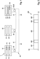
- Fig. 1 shows, as an example, a bus system 1, which is configured, in particular, fundamentally for a CAN bus system, a CAN FD bus system, a CAN FD successor bus system, and/or modifications thereof, as described below.
- the CAN FD successor bus system is referred to below as CAN XL.
- the bus system 1 can be used in a vehicle, in particular a motor vehicle, an aircraft, etc., or in a hospital, etc.
- the bus system 1 has a plurality of subscriber stations 10, 20, 30, each connected to a bus 40 with a first bus wire 41 and a second bus wire 42.
- the bus wires 41, 42 can also be called CAN_H and CAN_L and are used for electrical signal transmission after coupling in the dominant levels or generating recessive levels for a signal in the transmit state.
- Messages 45, 46 in the form of signals can be serially transmitted between the individual subscriber stations 10, 20, 30 via the bus 40.
- the subscriber stations 10, 20, 30 are, for example, control units, sensors, display devices, etc. of a motor vehicle.
- the subscriber station 10 has a communication control device 11, a transmitting/receiving device 12, a first mode switching module 15 and a second mode switching module 16.
- the subscriber station 20 has a communication control device 21 and a transmitting/receiving device 22.
- the subscriber station 30 has a communication control device 31, a transmitting/receiving device 32, a first mode switching module 35 and a second mode switching module 36.
- the transmitting/receiving devices 12, 22, 32 of the subscriber stations 10, 20, 30 are each directly connected to the bus 40, even if this is not the case in Fig. 1 is not illustrated.
- each subscriber station 10, 20, 30, the messages 45, 46 are exchanged bit by bit in coded form in the form of frames via a TXD line and an RXD line between the respective communication control device 11, 21, 31 and the associated transmitting/receiving devices 12, 22, 32. This is described in more detail below.
- the communication control devices 11, 21, 31 each serve to control communication of the respective subscriber station 10, 20, 30 via the bus 40 with at least one other subscriber station of the subscriber stations 10, 20, 30 that are connected to the bus 40.
- the communication control devices 11, 31 create and read first messages 45, which are, for example, modified CAN messages 45, which are also referred to below as CAN XL messages 45.
- the CAN XL messages 45 are constructed on the basis of a CAN FD successor format, which with regard to Fig. 2 described in more detail.
- the communication control devices 11, 31 can also be configured to provide a CAN XL message 45 or a CAN FD message 46 to the transmitting/receiving devices 12, 32 or to receive one from them as needed.
- the communication control devices 11, 31 thus create and read a first message 45 or a second message 46, wherein the first and second messages 45, 46 differ in their data transmission standard, namely CAN XL or CAN FD in this case.
- the communication control device 21 can be designed like a conventional CAN controller according to ISO 11898-1:2015, in particular like a CAN FD tolerant Classical CAN controller or a CAN FD controller.
- the communication control device 21 creates and reads second messages 46, for example Classical CAN messages or CAN FD messages 46.
- the CAN FD messages 46 can comprise a number of 0 to 64 data bytes, which can also be transmitted at a significantly faster data rate than with a Classical CAN message can be transmitted. In the latter case, the communication control device 21 is designed like a conventional CAN FD controller.
- the transmitting/receiving devices 12, 32 can be designed as CAN XL transceivers, except for the differences described in more detail below.
- the transmitting/receiving devices 12, 32 can additionally or alternatively be designed as a conventional CAN FD transceiver.
- the transmitting/receiving device 22 can be designed as a conventional CAN transceiver or CAN FD transceiver.
- Fig. 2 shows a CAN XL frame 450 for message 45, as sent by the transceiver 12 or the transceiver 32.
- the CAN XL frame 450 is divided into different communication phases 451 to 455 for CAN communication on the bus 40, namely an arbitration phase 451, a first switching phase 452, a data phase 453, a second switching phase 454, and a frame end phase 455.
- a bit is sent at the beginning, also called the SOF bit, which indicates the start of the frame or start of frame.
- an identifier with, for example, 11 bits is also sent to identify the sender of message 45.
- the identifier is used to negotiate bit by bit between the subscriber stations 10, 20, 30 which subscriber station 10, 20, 30 wishes to send message 45, 46 with the highest priority and therefore receives exclusive access to bus 40 of bus system 1 for the next transmission time in the switchover phase 452 and the subsequent data phase 453.
- the first switching phase 452 prepares the switchover from the arbitration phase 451 to the data phase 453.
- the switching phase 452 can have a bit that has the bit duration T_B1 of a bit of the arbitration phase 451 and is transmitted at least partially with the physical layer of the arbitration phase 451.
- the first switching phase 452 logically belongs to the arbitration phase 451.
- the transmitting/receiving device 12, 32 is signaled that the device 12, 32 should switch to another mode or operating mode, namely to the physical layer of the data phase 453.
- the bits of frame 450 are sent with the physical layer of the data phase 453 and with a bit duration T_B2 that is shorter than the bit duration T_B1 of a bit of the arbitration phase 451.
- the payload of the CAN XL frame 450 or message 45 is sent.
- the payload can also be referred to as the data field of message 45.
- a data length code for example 11 bits long, can be sent.
- the code can, for example, assume values from 1 to 2048 or another value with a step size of 1.
- the data length code can alternatively comprise fewer or more bits, so that the value range and step size can assume different values. This is followed by further fields, such as the header checksum field.
- the payload of CAN XL frame 450 or message 45 is then sent.
- a checksum field can, for example, contain a checksum of the data of data phase 453 and the data of arbitration phase 451.
- the sender of message 45 can insert stuff bits into the data stream as an inverse bit after a predetermined number of identical bits, in particular 10 identical bits.
- the checksum is a frame checksum F_CRC, with which all relevant bits of frame 450 up to the checksum field are secured. Stuff bits in data phase 453, for example, are not secured because these bits secure frame 450 itself and are thus used for error detection.
- the switch from the data phase 453 to the frame end phase 455 is prepared. This means that a switch back to the transmission mode according to the arbitration phase 451 takes place.
- the switching phase 454 can have a bit that has the bit duration T_B1 of a bit of the arbitration phase 451 and is transmitted at least partially with the physical layer of the data phase 453.
- the second switching phase 454 logically belongs to the frame end phase 455, in which the same transmission mode is used as in the arbitration phase 451.
- the transmitting/receiving device 12, 32 is signaled that the device 12, 32 should switch to another mode or operating mode, namely to the physical layer of the arbitration phase 451.
- At least one acknowledge bit can be included in an end field after two bits AL2, AH2. This can be followed by a sequence of seven identical bits, indicating the end of the CAN XL frame 450. With the at least one acknowledge bit (ACK), a receiver can indicate whether or not it has correctly received the CAN XL frame 450 or message 45.
- ACK acknowledge bit
- a physical layer similar to CAN and CAN-FD is used at least in the arbitration phase 451 and the frame end phase 455. Additionally, a physical layer similar to CAN and CAN-FD can be used at least partially in the switchover phases 452 and 454, i.e., in the first switchover phase 452 at the beginning and in the second switchover phase 454 at the end.
- the physical layer corresponds to the physical layer or Layer 1 of the well-known OSI model (Open Systems Interconnection Model).
- the CSMA/CR procedure results in so-called recessive states on the bus 40, which can be overwritten by other subscriber stations 10, 20, 30 with dominant states on the bus 40.
- the bit rate in the arbitration phase 451, the frame end phase 454 is selected to be slower than in the data phase 453 of the frame 450.
- the bit rate in the phases 451, 455 is selected as 500 kbit/s, which results in a bit duration or bit time of approximately 2 ⁇ s
- the bit rate in the data phase 453 is selected as 5 to 10 Mbit/s or more, which results in a bit time of approximately 0.1 ⁇ s. and shorter.
- the bit time of the signal in the other communication phases 451, 452, 454, 455 is at least a factor of 10 greater than the bit time of the signal in the data phase 453.
- a sender of message 45 begins sending bits of the switching phase 452 and the subsequent data phase 453 to bus 40 only when subscriber station 10 as the sender has won the arbitration and subscriber station 10 as the sender thus has exclusive access to bus 40 of bus system 1 for sending.
- the sender can either switch to the faster bit rate and/or the other physical layer after part of the switching phase 452 or switch to the faster bit rate and/or the other physical layer only with the first bit, i.e. with the start of the subsequent data phase 453.
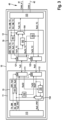
- Fig. 3 shows the basic structure of the subscriber station 10 with the communication control device 11, the transmitting/receiving device 12, and the operating mode switching modules 15, 16.
- the operating mode switching module 15 of the communication control device 11 is constructed symmetrically to the operating mode switching module 16 of the transmitting/receiving device 12.
- the operating mode switching module 15 can also be called the first operating mode switching module.
- the operating mode switching module 16 can also be called the second operating mode switching module.
- the subscriber station 30 is constructed in a similar way as in Fig. 3 shown, except that block 35 is not integrated into communication control device 31, but is provided separately from communication control device 31 and transmitting/receiving device 32. Therefore, subscriber station 30 and block 35 are not described separately.
- the functions of mode switching module 15 described below are identical in mode switching module 35.
- the functions of mode switching module 16 described below are identical in mode switching module 36.
- the block 16 is not integrated into the transmitting/receiving device 12, but is provided separately from the communication control device 11 and the transmitting/receiving device 12.
- the transmitting/receiving device 12 is connected to the bus 40, more precisely its first bus wire 41 for CAN_H and its second bus wire 42 for CAN_L. During operation of the bus system 1, the transmitting/receiving device 12 converts a transmit signal TxD of the communication control device 11 into corresponding signals CAN_H and CAN_L for the bus wires 41, 42 and transmits these signals CAN_H and CAN_L to the bus 40.
- signals CAN_H and CAN_L are mentioned here for the transmitting/receiving device 12, these are to be understood with regard to the message 45 as signals CAN-XL_H and CAN-XL_L, which in the data phase 453 are separated from the conventional signals CAN_H and CAN_L differ in at least one feature, in particular with regard to the formation of the bus states for the different data states of the TxD signal and/or with regard to the voltage or the physical layer and/or the bit rate.
- a differential signal VDIFF CAN_H - CAN_L is generated on bus 40. Except for an idle or standby state, the transceiver 12 and its receiver always listen for a transmission of data or messages 45, 46 on bus 40 during normal operation, regardless of whether the subscriber station 10 is the sender of the message 45 or not.
- the transceiver 12 generates a receive signal RxD from the CAN_H and CAN_L signals received from bus 40 and forwards this signal to the communication control device 11, as described in more detail below.
- the structure of the subscriber station 10 described below provides a robust and simple way to transmit bits symmetrically by means of signals between the communication control device 11 and the transceiver device 12, i.e., without the bits changing their duration. This is particularly advantageous during the transmission of data during the data phase 453 of a frame 450.
- the communication control device 11 has a first bidirectional connection 111 for a digital transmission signal TxD, a second bidirectional connection 112 for a digital reception signal RxD, and a communication control module 113.
- the transmission/reception device 12 has, in addition to the operating mode switching module 16, a first bidirectional connection 121 for the digital transmission signal TxD, a second bidirectional connection 122 for the digital reception signal RxD, and a transmission/reception module 123.
- the connections 111, 112, 121, 122 can be operated bidirectionally with the aid of the modules 15, 16 and corresponding signals, namely can be switched either as an output or an input, as described below.
- the communication control device 11 is designed as a microcontroller or has a microcontroller.
- the communication control device 11 processes signals from any application, for example, a control unit for an engine, a safety system for a machine or a vehicle, or other applications.
- a system ASIC Application-Specific Integrated Circuit
- the system ASIC can incorporate, among other things, the transmitting/receiving device 12 and a power supply device (not shown), which supplies the transmitting/receiving device 12 with electrical energy.
- the power supply device typically supplies a CAN_Supply voltage of 5 V. However, depending on requirements, the power supply device can supply a different voltage with a different value and/or be configured as a current source.
- the communication control module 113 is a protocol controller that implements the CAN protocol, in particular the protocol for CAN XL or CAN FD.
- the communication control module 113 is configured to output the following output signals or receive the following input signals.
- the TxD_PRT signal is an output signal corresponding to the transmit signal TxD.
- the RxD_PRT signal is an input signal corresponding to the receive signal RxD.
- the communication control module 113 is configured to generate and output the following control signals TX_DM, RX_DM.
- the control signal TX_DM is an output signal and indicates whether the transceiver 12 should operate in the TX-DataPhaseMode operating mode or not.
- This operating mode is also called FAST_TX Mode or first operating mode.
- the subscriber station 10 In the TX-DataPhaseMode operating mode, the subscriber station 10 has won the arbitration in the arbitration phase 451 and is in the following Data phase 453, transmitter of frame 450. In this case, subscriber station 10 can also be referred to as the transmitting node.
- TX-DataPhaseMode the transceiver device 12 should use the physical layer for data phase 453 and drive the bus wires CAN_H and CAN_L.
- the RX_DM control signal is an output signal and indicates whether the transceiver 12 should operate in RX-DataPhaseMode or not. This mode is also called FAST_RX Mode or second mode.
- RX-DataPhaseMode the subscriber station 10 has lost the arbitration in the arbitration phase 451 and is only a receiver, i.e., not a transmitter, of frame 450 in the subsequent data phase 453. In this case, the subscriber station 10 can also be referred to as a receiving node.
- RX-DataPhaseMode the transceiver 12 should use the physical layer for the data phase 453, but should not drive the CAN_H and CAN_L bus wires.
- the transceiver If the transceiver is neither in TX-DataPhaseMode nor in RX-DataPhaseMode, it is in the so-called ArbitrationPhaseMode, i.e. the mode used in the arbitration phase 451 and the frame end phase 455. In this mode, the physical layer is used, which can be used to transmit dominant and recessive bus states.
- the circuit for signaling the operating mode to be activated to the transceiver 12 is not shown here. Signaling is also carried out, in particular, via the TxD port 111 and/or RxD port 112.
- the mode switching module 15 has a direction control block 151, an encoding block 152, a decoding block 153, and a multiplexer 154.
- the first mode switching module 15 receives the aforementioned signals output by the communication control module 113.
- the direction control block 151 generates the switching signals DIR_TxD and DIR_RxD from the control signals TX_DM and RX_DM of the communication control module 113.
- the switching signal DIR_TxD controls the direction DIR, more precisely the transmission direction, of the first bidirectionally switchable port 111 of the communication control device 11. In other words, the switching signal DIR_TxD controls the direction of the TxD port 111 of the device 11.
- the switching signal DIR_RxD controls the direction DIR, more precisely the transmission direction, of the second bidirectionally switchable port 112 of the communication control device 11. In other words, the switching signal DIR_RxD controls the direction of the RxD port 112 of the device 11.
- the communication control module 113 can transmit a frame 450 to be sent on the bus 40 as a differential signal via the ports 111, 112, as described in more detail below.
- the communication control module 113 transmits a frame 450 and the TX_DM signal is set, the direction of the TxD port 111 and the direction of the RxD port 112 are switched to output.
- the communication control module 113 can receive a frame 450 transmitted over the bus 40 as a differential signal via the ports 111, 112, as described in more detail below.
- the communication control module 113 receives a frame 450 and the RX_DM signal is set, the direction of the TxD port 111 and the direction of the RxD port 112 are switched to input.
- the coding block 152 generates a signal TxD2 from the signal TxD_PRT, i.e., the transmit signal TxD.
- the signal TxD2 is an inverse signal of the signal TxD_PRT.
- the coding block 152 outputs the signal TxD2 to terminal 112. If terminals 111, 112 are switched to output, as previously described, The communication control device 11 can output the signals TxD_PRT, TxD2 as a differential output signal to the transmitting/receiving device 12 via the terminals 111, 112.
- the coding block 152 is an inverter that inverts the signal TxD_PRT.
- the decoder block 153 is connected at its input to terminals 111, 112. If terminals 111, 112 are connected to input, as previously described, the decoder block 153 receives a differential input signal from terminals 111, 112 consisting of a signal RxD1 and a signal RxD2. The decoder block 153 decodes the signals RxD1 and RxD2 to the non-differential signal RxD_PRT. The decoder block 153 outputs the signal RxD_PRT to the multiplexer 154.
- the communication control module 113 controls the multiplexer 154 with the control signal RX_DM. Depending on the signal value of the control signal RX_DM, it is selected whether the signal decoded by the decoding block 153 or the signal RxD1 from the terminal 112 is provided to the communication control module 113 as the signal RxD_PRT.
- the transmitting/receiving module 123 is configured to transmit and/or receive messages 45, 46 according to the CAN protocol, in particular messages according to the CAN XL or CAN FD protocol, as previously described.
- the transmitting/receiving module 123 establishes the connection to the physical medium, i.e., the bus 40 with the bus wires 41, 42.
- the transmitting/receiving module 123 drives and decodes the CAN_H and CAN_L signals for the bus wires 41, 42 and the bus 40, respectively.
- the transmitting/receiving module 123 is also configured to output the following output signals or receive the following input signals.
- the RxD_TC signal is an output signal corresponding to a digital receive signal generated by the transceiver module 123 from the differential CAN_H, CAN_L signal from the bus 40.
- the TxD_TC signal is an input signal corresponding to the transmit signal TxD, i.e., the signal generated by the communication control module 113 for transmission on the bus 40.
- the transmit/receive module 123 is configured to generate and output the following control signals TX_DM_TC, RX_DM_TC.
- the control signal TX_DM_TC is an output signal and indicates whether the transceiver 12 is operating in the TX-DataPhaseMode mode or is switched to act as a transmitter of frame 450 in the data phase 453, as previously described. This is an operating mode in which the transceiver module 123 transmits 453 bits on the bus 40 in the data phase, thus driving the bus 40.
- the control signal RX_DM_TC is an output signal and indicates whether the transceiver 12 is operating in the RX-DataPhaseMode operating mode or is switched to act only as a receiver, i.e., not as a transmitter, of frame 450 in the data phase 453, as previously described. This is an operating mode in which the transceiver module 123 only receives bits from the bus 40 in the data phase 453, i.e., does not drive the bus 40.
- the second mode switching module 16 has a direction control block 161, an encoding block 162, a decoding block 163, and a multiplexer 164.
- the second mode switching module 16 receives the aforementioned signals output by the transmitting/receiving module 123.
- the direction control block 161 generates the switching signals DIR_TxD_TC and DIR_RxD_TC from the control signals TX_DM_TC and RX_DM_TC of the transmit/receive module 123.
- the switching signal DIR_TxD_TC controls the direction DIR, more precisely the transmission direction, of the first bidirectionally switchable port 121 of the transmit/receive device 12. In other words, the switching signal DIR_TxD_TC controls the direction of the TxD port 121 of the device 12.
- the switching signal DIR_RxD_TC controls the direction DIR, more precisely the transmission direction, of the second bidirectionally switchable port 122 of the transmit/receive device 12. In other words, the switching signal DIR_RxD_TC controls the direction of the RxD port 122 of the device 12.
- the transmit/receive module 123 can send a frame 450 sent by another subscriber station via the bus 40 as a differential signal via the ports 121, 122 to the communication control device 11, as described in more detail below.
- the transmit/receive module 123 receives a frame 450 and the RX_DM_TC signal is set, the direction of the TxD port 121 and the direction of the RxD port 122 are switched to output.
- the transmit/receive module 123 can receive a frame 450 to be transmitted on the bus 40 as a differential signal via its ports 121, 122 from the communication control device 11. In particular, if the transmit/receive module 123 transmits a frame 450 on the bus 40 and the TX_DM_TC signal is set, the direction of the TxD port 121 and the direction of the RxD port 122 are switched to input.
- the coding block 162 generates a signal RxD2_TC from the signal RxD_TC, i.e., the received signal RxD.
- the signal RxD2_TC is an inverse signal of the signal RxD_TC.
- the coding block 162 outputs the signal RxD2_TC to the terminal 121. If the terminals 121, 122 are switched to output, as previously described, the transmitting/receiving device 12 can output the signals RxD2_TC, RxD_TC as a differential output signal to the communication control device 11 via the terminals 121, 122.
- the coding block 162 is an inverter that inverts the signal RxD_TC.
- the decoder block 163 is connected at its input to the terminals 121, 122. If the terminals 121, 122 are switched to input, as described above, the decoder block 163 receives from the terminals 121, 122 a differential input signal consisting of a signal TxD1_TC and a signal TxD2_TC. The decoding block 163 decodes the signals TxD1_TC and TxD2_TC into the non-differential signal TxD_TC. The decoding block 163 outputs the signal TxD_TC to the multiplexer 154.
- the transmit/receive module 123 controls the multiplexer 164 with the control signal TX_DM_TC. Depending on the signal value of the control signal TX_DM_TC, it is selected whether the signal decoded by the decoding block 163 or the signal TxD1_TC from the terminal 121 is provided to the transmit/receive module 123 as the signal TxD_TC.
- the communication control device 11 transmits the bit stream of the serial transmission signal TxD as a differential signal via the TxD and RxD terminals 111, 112.
- the transceiver 12 receives this differential signal at its TxD and RxD terminals 121, 122 and decodes this differential signal into a non-differential signal TxD_TC.
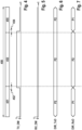
- Fig. 4 to Fig. 7 show an example of the signal waveforms of the previously described signals in the communication control device 11 when the subscriber station 10 is the sender of the message 45 and thus the transmitting/receiving device 12 is switched to the TX-DataPhaseMode operating mode in the data phase 453.
- Fig. 6 and Fig. 7 the designation "P1" for input and the designation "P2" for output.
- the communication control device 11 and the transmitting/receiving device 12 use the ports 111, 112, 121, 122 of the subscriber station 10 as usual to transmit the data.
- the communication control device 11 transmits via the TxD port 111 and simultaneously receives the data from the bus 40 via the RxD port 112.
- the subscriber station 10 as a transmitting node transmits exclusively, as in Fig. 4 to Fig. 7 shown.
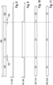
- the subscriber station 10 as a receiving node in the faster operating mode of the transmitting/receiving device 12 only receives, as in Fig. 8 to Fig. 11 shown.
- Fig. 8 to Fig. 11 show an example of the signal waveforms of the previously described signals in the communication control device 11 when the subscriber station 10 is not a sender of the message and thus the transmitting/receiving device 12 is switched to the RX-DataPhaseMode operating mode.
- Fig. 10 and Fig. 11 the designation "P1" for input and the designation "P2" for output.
- the transceiver 12 transmits the bit stream of the serial receive signal RxD as a differential signal via the TxD and RxD terminals 121, 122.
- the communication control device 11 receives this differential signal at its TxD and RxD terminals 111, 112 and decodes this differential signal to the non-differential signal RxD_PRT.
- the data is transmitted during the arbitration phase 451 and frame end phase 455 via the terminals 111, 112, 121, 122, as previously described for Fig. 4 to Fig. 7 described.
- TX-DataPhaseMode operating modes of the transceiver 12 is no longer necessary for the subscriber stations 10, 30 in the data phase 453.
- the communication control device 11 and the transceiver 12 use the two connections 111, 112, 121, 122 for the signals RxD, TxD in the same direction to transmit a differential transmission signal TxD (first operating mode of the data phase 453) or a differential reception signal RxD (second operating mode of the data phase 453).
- a first modification of the aforementioned configuration of the modules 15, 16 it is possible for at least one of the modules 15, 16 to only enable switching to the TX-DataPhaseMode operating mode.
- Such a variant can be advantageous, for example, for a subscriber station 10, 20 of the bus system 1, which itself only needs to send signals, but not receive signals from Bus 40 must receive in order to perform its function.
- An example of the design of such a subscriber station is a pure control element, whose control is transmitted via bus 40, but receives or generates the event for the control independently of the communication on the bus.
- modules 15, 16 it is possible for at least one of modules 15, 16 to only allow switching to the RX-DataPhaseMode operating mode.
- a subscriber station 10, 20 of bus system 1 which does not need to send any signals itself, but only needs to receive signals from bus 40 to perform its function.
- An example of the configuration of such a subscriber station is a sensor, in particular a rotary encoder, actuator, etc.
- the previously described functions of the devices 11, 12 can also be used for another modification of CAN FD and/or CAN, at least for the transmission of the user data.
- data phase 453 Due to the described configuration of device(s) 11, 12, 32, 35, much higher data rates can be achieved in data phase 453 than with CAN or CAN-FD. Furthermore, the data length in the data field of data phase 453 can be freely selected, as previously described. This allows the advantages of CAN with regard to arbitration to be retained, while still allowing a larger amount of data to be transmitted very securely and thus effectively in a shorter time than before.
- Fig. 12 to Fig. 16 show signal waveforms at the subscriber station 10 in a second embodiment. This shows the transition between the data phase 453 and the frame end phase 455 when the subscriber station 10 is the transmitter of the frame 450.
- the transmission mode corresponds to the arbitration phase 451.
- the communication control device 11 sends in the frame end phase 455 via the TxD port 111, so that the port 111 is set to output (designation P2), and simultaneously receives the data from the bus 40 via the RxD port 112, so that the port 111 is set to input (designation P1), as in Fig. 16 shown.
- the communication control device 11 uses its two terminals 111, 112 as output (designation P2) in Fig. 15 and Fig. 16 ) and the transceiver 12 uses its two terminals 121, 122 as input (designation P1).
- a differential signal TxD_PRT, TxD2 is transmitted from the terminals 111, 112 to the terminals 121, 122, which are Fig. 13 and Fig. 14 are designated as TxD, RxD.
- the TxD signal according to Fig. 13 at the terminal 111 has bits with a bit duration T_B2.
- the signal RxD according to Fig. 14 at terminal 112 also has bits with the bit duration T_B2, since it corresponds to the inverse TxD signal.
- the mode switching module 15 is designed to send a non-differential signal via its two terminals 111, 112 to signal the switching, as shown in Fig. 13 and Fig. 14
- the transmitting/receiving device can 12 recognize that the transmitting/receiving device 12 should now switch its operating mode to the operating mode of the arbitration phase 451.
- signaling of the operating mode change from the arbitration phase 451 to the data phase 453, i.e., to one of the operating modes RX-DataPhaseMode, TX-DataPhaseMode of the transmitting/receiving device 12, can be carried out via the RxD port 112.
- the communication control device 11 briefly drives the RxD port 112 more strongly than the transmitting/receiving device 12 drives its RxD port 122 for the purpose of signaling the operating mode change.
- the second embodiment also has the advantage that no further connection or pin or port is necessary for the devices 11, 12 and thus the solution is very cost-effective.
- the transceiver 12 and/or the transceiver 32 in particular the operating mode switching module 15 and/or the operating mode switching module 16, can be configured to signal something to the communication control device 11, in particular the communication control module 113, when receiving in the RX-DataPhaseMode operating mode.
- the transceiver 12, 32 transmits a non-differential signal via the TxD and RxD terminals 121, 122 in an additional operating mode of the data phase 453, as described for the terminals 111, 112 with reference to the second exemplary embodiment.
- the signaling S of the transceiver devices 12, 32 may contain or be additional information that is in addition to the information of the signals exchanged in the bus system 1 with the messages 45, 46 between subscriber stations 10, 30 of the bus system 1.
- the additional information enables internal communication of the devices 11, 12 or the devices 31, 32.
- the invention can be used in any communication network and/or communication method that uses two different communication phases, in which the bus states generated for the different communication phases differ.
- the invention can be used in interfaces that require a switching signal from a protocol controller or module 113 for different communication phases and/or that require data exchange between devices 11, 12.
- the previously described bus system 1 according to the exemplary embodiments is described using a bus system based on the CAN protocol.
- the bus system 1 according to the exemplary embodiments can also be another type of communications network in which data can be transmitted serially at two different bit rates. It is advantageous, but not a mandatory requirement, that exclusive, collision-free access of a subscriber station 10, 20, 30 to a common channel is guaranteed in the bus system 1, at least for certain time periods.
- the number and arrangement of the subscriber stations 10, 20, 30 in the bus system 1 of the exemplary embodiments is arbitrary.
- the subscriber station 20 can be omitted from the bus system 1. It is possible for one or more of the subscriber stations 10 or 30 to be present in the bus system 1. It is conceivable for all subscriber stations in the bus system 1 to be designed identically, i.e., only subscriber station 10 or only subscriber station 30 to be present.
Landscapes
- Engineering & Computer Science (AREA)
- Computer Networks & Wireless Communication (AREA)
- Signal Processing (AREA)
- Small-Scale Networks (AREA)
Claims (15)
- Dispositif de commande de communication (11) pour une station d'abonné (10) d'un système de bus série (1), comprenantun module de commande de communication (113) pour produire un signal d'émission (TxD_PRT) pour commander une communication de la station d'abonné (10) avec au moins une autre station d'abonné (10 ; 20 ; 30) du système de bus (1), dans lequel système de bus (1) au moins une première phase de communication (451, 452, 454, 455) et une deuxième phase de communication (453) sont utilisées pour échanger des messages (45 ; 46) entre stations d'abonné (10, 20, 30) du système de bus (1) dans une trame (450) pour un message (45 ; 46),une première borne (111) pour émettre, dans un mode de fonctionnement de la première phase de communication (451, 452, 454, 455) d'une trame (450), le signal d'émission (TxD_PRT) à un dispositif d'émission/réception (12 ; 32) qui est configuré pour émettre le signal d'émission (TxD) sur un bus (40) du système de bus (1),une deuxième borne (122) pour recevoir, dans le mode de fonctionnement de la première phase de communication (451, 452, 454, 455) de la trame (450), un signal de réception numérique (RxD) du dispositif d'émission/réception (12 ; 32), etun module de commutation de mode de fonctionnement (15) pour commuter le dispositif de transmission de la première et de la deuxième borne (111, 112) dans la deuxième phase de communication (453) de la trame (450) dans la même direction pour une transmission de signal différentielle par l'intermédiaire de la première et de la deuxième borne (111, 112).
- Dispositif de commande de communication (11) selon la revendication 1,dans lequel le module de commutation de mode de fonctionnement (15) est configuré pour commuter la première et la deuxième borne (111, 112) en tant que sortie dans un premier mode de fonctionnement de la deuxième phase de communication (453), et pour produire un signal d'émission numérique inverse (TxD2) à partir du signal d'émission (TxD_PRT) et pour sortir le signal d'émission (TxD_PRT) à la première borne (111) et le signal d'émission numérique (TxD2) inverse à celui-ci à la deuxième borne (112), et/oudans lequel le module de commutation de mode de fonctionnement (15) est configuré pour commuter la première et la deuxième borne (111, 112) en tant qu'entrée dans le deuxième mode de fonctionnement de la deuxième phase de communication (453), et pour produire un signal de réception non différentiel (RxD_PRT) à partir du signal de réception différentiel (RxD1, RxD2) reçu à la première et à la deuxième borne (111, 112) et pour le sortir au module de commande de communication (113).
- Dispositif de commande de communication (11) selon la revendication 1 ou 2, dans lequel le module de commutation de mode de fonctionnement (15) est configuré pour produire et sortir dans le premier mode de fonctionnement de la deuxième phase de communication (453) aux deux bornes (111, 112) pendant une durée prédéterminée (T) les deux signaux d'émission (TxD_PRT, TxD2) au même niveau afin de signaler au dispositif d'émission/réception (12) que le mode de fonctionnement du dispositif d'émission/réception (12) est à commuter du premier mode de fonctionnement de la deuxième phase de communication (453) au mode de fonctionnement de la première phase de communication (451, 452, 454, 455).
- Dispositif de commande de communication (11) selon l'une quelconque des revendications précédentes, dans lequel le module de commutation de mode de fonctionnement (15) est configuré pour signaler au dispositif d'émission/réception (12) par l'intermédiaire de la première ou de la deuxième borne (111 ; 112) que le dispositif d'émission/réception (12) doit commuter son mode de fonctionnement du mode de fonctionnement de la première phase de communication (451, 452, 454, 455) dans un mode de fonctionnement prédéterminé de la deuxième phase de communication (453).
- Dispositif de commande de communication (11) selon l'une quelconque des revendications précédentes, dans lequel le module de commande de communication (113) est configuré pour produire le signal d'émission (TxD_PRT) dans la première phase de communication (451, 452, 454, 455) avec des bits ayant un premier temps de bit (T_B1) qui est supérieur au moins d'un facteur 10 à un deuxième temps de bit (T_B2) des bits produits par le module de commande de communication (113) dans la deuxième phase de communication (453) dans le signal d'émission (TxD_PRT).
- Dispositif d'émission/réception (12 ; 32) pour une station d'abonné (10 ; 30) d'un système de bus série (1), comprenantun module d'émission/réception (123) pour émettre un signal d'émission (TxD_TC) sur un bus (40) du système de bus (1), dans lequel système de bus (1), pour échanger des messages (45, 46) entre des stations d'abonné (10, 20, 30) du système de bus (1), dans une trame (450) pour un message (45 ; 46), au moins une première phase de communication (451, 452, 454, 455) et une deuxième phase de communication (453) sont utilisées, et pour produire un signal de réception numérique (RxD_TC) à partir du signal reçu du bus (40),une première borne (121) pour recevoir, dans un mode de fonctionnement de la première phase de communication (451, 452, 454, 455) d'une trame (450), un signal d'émission (TxD) d'un dispositif d'émission/réception (11 ; 31),une deuxième borne (122) pour émettre, dans un mode de fonctionnement de la première phase de communication (451, 452, 454, 455) de la trame (450), le signal de réception numérique (RxD_TC) au dispositif de commande de communication (11 ; 31), etun module de commutation de mode de fonctionnement (16) pour commuter la direction de transmission de la première et de la deuxième borne (121, 122) dans la deuxième phase de communication (453) de la trame (450) dans la même direction pour une transmission de signal différentielle par l'intermédiaire de la première et de la deuxième borne (121, 122).
- Dispositif d'émission/réception (12 ; 32) selon la revendication 6,dans lequel le module de commutation de mode de fonctionnement (16 ; 36) est configuré pour commuter, dans un premier mode de fonctionnement de la deuxième phase de communication (453), la première et la deuxième borne (121, 122) en tant qu'entrée, et pour produire un signal d'émission non différentiel (TxD_TC) à partir du signal de réception différentiel (TxD1_TC, TxD2_TC) reçu à la première et à la deuxième borne (121, 122), et/oudans lequel le module de commutation de mode de fonctionnement (16 ; 36) est configuré pour commuter, dans un deuxième mode de fonctionnement de la deuxième phase de communication (453), la première et la deuxième borne (121, 122) en tant que sortie, et pour produire un signal de réception numérique inverse (RxD2_TC) à partir du signal de réception numérique (RxD_TC), et pour sortir le signal de réception numérique (RxD_TC) à la deuxième borne (122) et le signal de réception numérique (RxD2_TC) inverse à celui-ci à la première borne (121).
- Dispositif d'émission/réception (12 ; 32) selon la revendication 6 ou 7, dans lequel le module de commutation de mode de fonctionnement (16) est configuré, dans le deuxième mode de fonctionnement de la deuxième phase de communication (453), pour produire et sortir aux deux bornes (121, 122) pendant une durée prédéterminée (T) les deux signaux de réception (RxD_TC, RxD2_TC) avec le même niveau pour signaler des informations supplémentaires au dispositif de commande de communication (12) qui s'ajoutent aux informations des signaux qui sont échangés dans le système de bus (1) avec les messages (45 ; 46) entre les stations d'abonné (10 ; 30) du système de bus (1).
- Dispositif d'émission/réception (12 ; 32) selon l'une quelconque des revendications 6 à 8,
dans lequel le module d'émission/réception (123) est configuré pour émettre le signal d'émission (TxD_TC) sous forme de signal différentiel (CAN_H, CAN_L) sur le bus (40). - Dispositif (11 ; 12 ; 32) selon l'une quelconque des revendications précédentes, dans lequel le module de commutation de mode de fonctionnement (15 ; 16 ; 36) est configuré pour sélectionner la direction de transmission de la première et de la deuxième borne (111, 112 ; 121, 122) en fonction d'un mode de fonctionnement sur lequel est commuté le dispositif d'émission/réception (12 ; 32).
- Dispositif (11 ; 12 ; 32) selon l'une quelconque des revendications précédentes, dans lequel le module de commutation de mode de fonctionnement (15 ; 16 ; 35 ; 36) présenteun bloc de commande de direction (151 ; 161) pour commander la direction de transmission de la première et de la deuxième borne (111, 112 ; 121, 122) en fonction du mode de fonctionnement du dispositif d'émission/réception (12 ; 32),un bloc de codage (152 ; 162) pour coder les signaux différentiels (TxD2 ; RxD2_TC),un bloc de décodage (153 ; 163) pour décoder les signaux différentiels (TxD2 ; RxD2_TC) à la première et à la deuxième borne (111, 112 ; 121, 122) en un signal non différentiel (TxD_TC ; RxD_PRT), etun multiplexeur (154 ; 164) pour sortir le signal non différentiel (TxD_TC ; RxD_PRT) produit par le bloc de décodage (153 ; 163) lorsque le dispositif d'émission/réception (12 ; 32) est commuté sur un mode de fonctionnement de la deuxième phase de communication (453).
- Dispositif (11 ; 12 ; 32) selon l'une quelconque des revendications précédentes, dans lequel le signal reçu du bus (40) dans la première phase de communication (451, 452, 454, 455) est produit avec une couche physique différente par rapport au signal reçu du bus (40) dans la deuxième phase de communication (453).
- Dispositif (11 ; 12 ; 31 ; 32) selon l'une des revendications précédentes, dans lequel on négocie dans la première phase de communication (451) laquelle des stations d'abonné (10, 20, 30) du système de bus (1) obtient un accès au bus (40) au moins temporairement exclusif, sans collision, dans la deuxième phase de communication (453) consécutive.
- Système de bus (1), comprenant un bus (40), et
au moins deux stations d'abonné (10 ; 20 ; 30) qui sont reliées l'une à l'autre par le bus (40) de telle sorte qu'elles peuvent communiquer en série entre elles et parmi lesquelles au moins une station d'abonné (10 ; 30) présente un dispositif de commande de communication (11 ; 31) selon l'une quelconque des revendications 1 à 5 et 10 à 13 ainsi qu'un dispositif d'émission/réception (12 ; 32) selon l'une quelconque des revendications 6 à 13. - Procédé de communication dans un système de bus série (1), dans lequel le procédé est effectué avec une station d'abonné (10 ; 30) pour un système de bus (1), dans lequel au moins une première phase de communication (451, 452, 454, 455) et une deuxième phase de communication (453) dans une trame (450) pour un message (45 ; 46) sont utilisées pour échanger des messages (45 ; 46) entre des stations d'abonné (10, 20, 30) du système de bus (1), dans lequel la station d'abonné (10 ; 30) présente un dispositif de commande de communication (11 ; 31) selon l'une quelconque des revendications 1 à 5 et 10 à 13 et un dispositif d'émission/réception (12 ; 32) selon l'une quelconque des revendications 6 à 13, et dans lequel le procédé présente les étapes consistant àcommuter, par un module de commutation de mode de fonctionnement (15 ; 35) pour le dispositif de commande de communication (11 ; 31), la direction de transmission de la première et de la deuxième borne (111, 112) pour le dispositif de commande de communication (11 ; 31) dans la deuxième phase de communication (453) de la trame (450) dans la même direction, etcommuter, par un module de commutation de mode de fonctionnement (16 ; 36) pour le dispositif d'émission/réception (12 ; 32), la direction de transmission de la première et de la deuxième borne (121, 122) pour le dispositif d'émission/réception (12 ; 32) dans la deuxième phase de communication (453) de la trame (450) dans la même direction qui est différente de la direction dans laquelle la première et la deuxième borne sont commutées pour le dispositif de commande de commutation, eteffectuer une transmission de signal différentielle entre le dispositif de commande de communication (11 ; 31) et le dispositif d'émission/réception (12 ; 32) par l'intermédiaire de la première et de la deuxième borne (111, 112) pour le dispositif de commande de communication (11 ; 31) et de la première et de la deuxième borne (121, 122) pour le dispositif d'émission/réception (12 ; 32).
Applications Claiming Priority (2)
| Application Number | Priority Date | Filing Date | Title |
|---|---|---|---|
| DE102020205257.3A DE102020205257A1 (de) | 2020-04-24 | 2020-04-24 | Kommunikationssteuereinrichtung und Sende-/Empfangseinrichtung für eine Teilnehmerstation eines seriellen Bussystems und Verfahren zur Kommunikation in einem seriellen Bussystem |
| PCT/EP2021/059203 WO2021213810A1 (fr) | 2020-04-24 | 2021-04-08 | Dispositif de commande de communication et dispositif d'émission/réception pour un poste d'abonné d'un système de bus série, et procédé de communication dans un système de bus série |
Publications (2)
| Publication Number | Publication Date |
|---|---|
| EP4140102A1 EP4140102A1 (fr) | 2023-03-01 |
| EP4140102B1 true EP4140102B1 (fr) | 2025-03-26 |
Family
ID=75438794
Family Applications (1)
| Application Number | Title | Priority Date | Filing Date |
|---|---|---|---|
| EP21717439.0A Active EP4140102B1 (fr) | 2020-04-24 | 2021-04-08 | Dispositif de commande de communication et dispositif d'émission/réception pour un poste d'abonné d'un système de bus série, et procédé de communication dans un système de bus série |
Country Status (6)
| Country | Link |
|---|---|
| US (1) | US11838145B2 (fr) |
| EP (1) | EP4140102B1 (fr) |
| JP (1) | JP7478254B2 (fr) |
| CN (1) | CN115413410B (fr) |
| DE (1) | DE102020205257A1 (fr) |
| WO (1) | WO2021213810A1 (fr) |
Family Cites Families (12)
| Publication number | Priority date | Publication date | Assignee | Title |
|---|---|---|---|---|
| DE102006019305A1 (de) * | 2006-04-26 | 2007-10-31 | Robert Bosch Gmbh | Verfahren zur Datenübertragung von und zu einem Steuergerät |
| DE102008000561A1 (de) * | 2008-03-07 | 2009-09-10 | Robert Bosch Gmbh | Kommunikationssystem mit einem CAN-Bus und Verfahren zum Betreiben eines solchen Kommunikationssystems |
| US8693379B2 (en) * | 2008-07-22 | 2014-04-08 | Panasonic Corporation | Communication system, communication device, and communication method |
| US10452504B2 (en) * | 2013-10-02 | 2019-10-22 | Nxp B.V. | Controller area network (CAN) device and method for emulating classic CAN error management |
| PT2866387T (pt) * | 2013-10-25 | 2017-01-12 | Amrona Ag | Sistema de transmissão e método para a produção de tal sistema de transmissão |
| JP6299692B2 (ja) * | 2015-07-17 | 2018-03-28 | 株式会社デンソー | 通信システム |
| DE102016224961A1 (de) | 2016-12-14 | 2018-06-14 | Robert Bosch Gmbh | Teilnehmerstation für ein Bussystem und Verfahren zur Datenübertragung in einem Bussystem |
| DE102018202164A1 (de) * | 2017-12-22 | 2019-06-27 | Robert Bosch Gmbh | Teilnehmerstation für ein serielles Bussystem und Verfahren zum Senden einer Nachricht in einem seriellen Bussystem |
| DE102019201230A1 (de) * | 2018-08-17 | 2020-02-20 | Robert Bosch Gmbh | Teilnehmerstation für ein serielles Bussystem und Verfahren zum Senden einer Nachricht in einem seriellen Bussystem |
| JP7133022B2 (ja) * | 2018-08-24 | 2022-09-07 | 日立Astemo株式会社 | 車載通信装置及び車載システム |
| DE102020205268A1 (de) * | 2020-04-27 | 2021-10-28 | Robert Bosch Gesellschaft mit beschränkter Haftung | Kommunikationssteuereinrichtung und Sende-/Empfangseinrichtung für eine Teilnehmerstation eines seriellen Bussystems und Verfahren zur Kommunikation in einem seriellen Bussystem |
| DE102020205278A1 (de) * | 2020-04-27 | 2021-10-28 | Robert Bosch Gesellschaft mit beschränkter Haftung | Kommunikationssteuereinrichtung und Sende-/Empfangseinrichtung für eine Teilnehmerstation eines seriellen Bussystems und Verfahren zur Kommunikation in einem seriellen Bussystem |
-
2020
- 2020-04-24 DE DE102020205257.3A patent/DE102020205257A1/de active Pending
-
2021
- 2021-04-08 WO PCT/EP2021/059203 patent/WO2021213810A1/fr not_active Ceased
- 2021-04-08 US US17/911,065 patent/US11838145B2/en active Active
- 2021-04-08 JP JP2022564180A patent/JP7478254B2/ja active Active
- 2021-04-08 EP EP21717439.0A patent/EP4140102B1/fr active Active
- 2021-04-08 CN CN202180030045.1A patent/CN115413410B/zh active Active
Also Published As
| Publication number | Publication date |
|---|---|
| JP7478254B2 (ja) | 2024-05-02 |
| US11838145B2 (en) | 2023-12-05 |
| WO2021213810A1 (fr) | 2021-10-28 |
| US20230111945A1 (en) | 2023-04-13 |
| DE102020205257A1 (de) | 2021-10-28 |
| JP2023522268A (ja) | 2023-05-29 |
| CN115413410A (zh) | 2022-11-29 |
| CN115413410B (zh) | 2024-05-03 |
| EP4140102A1 (fr) | 2023-03-01 |
Similar Documents
| Publication | Publication Date | Title |
|---|---|---|
| EP3918757B1 (fr) | Station d'abonné pour système de bus série et procédé de communication dans un système de bus série | |
| WO2020120553A1 (fr) | Dispositif pour une station d'abonné d'un système de bus série et procédé de communication dans un système de bus série | |
| EP3970324B1 (fr) | Dispositif émetteur/récepteur et dispositif de commande de communication pour une station d'abonné d'un système de bus série et procédé de communication dans un système de bus série | |
| EP3977683B1 (fr) | Dispositif pour une station d'abonné d'un système de bus série et procédé de communication dans un système de bus série | |
| DE102019200289A1 (de) | Rahmenabschirmeinheit, Teilnehmerstation für ein serielles Bussystem und Verfahren zur Kommunikation in einem seriellen Bussystem | |
| EP3895384B1 (fr) | Unité de détection de recouvrement pour un poste d'abonné d'un système de bus série et procédé de communication dans un système de bus série | |
| WO2020120555A1 (fr) | Station d'abonnés pour un système de bus série et procédé de communication dans un système de bus série | |
| DE102020205268A1 (de) | Kommunikationssteuereinrichtung und Sende-/Empfangseinrichtung für eine Teilnehmerstation eines seriellen Bussystems und Verfahren zur Kommunikation in einem seriellen Bussystem | |
| DE102020205278A1 (de) | Kommunikationssteuereinrichtung und Sende-/Empfangseinrichtung für eine Teilnehmerstation eines seriellen Bussystems und Verfahren zur Kommunikation in einem seriellen Bussystem | |
| WO2020088999A1 (fr) | Station d'abonné pour un système de bus en série et procédé d'envoi d'un message dans un système de bus en série | |
| EP4144044B1 (fr) | Module d'interface pour un dispositif de commande de communication, dispositif de transmission/réception pour une station d'abonné d'un système de bus série, et procédé de communication dans un système de bus série | |
| DE102021200081A1 (de) | Kommunikationssteuereinrichtung für eine Teilnehmerstation für ein serielles Bussystem und Verfahren zur Kommunikation in einem seriellen Bussystem | |
| EP4140102B1 (fr) | Dispositif de commande de communication et dispositif d'émission/réception pour un poste d'abonné d'un système de bus série, et procédé de communication dans un système de bus série | |
| EP4094407B1 (fr) | Dispositif d'émission/réception et dispositif de commande de communication pour une station d'abonné d'un système de bus série, et procédé de communication dans un système de bus série | |
| EP4193574B1 (fr) | Station d'abonné d'un système de bus série et procédé de communication dans un système de bus série | |
| WO2021148351A1 (fr) | Dispositif d'émission/réception et dispositif de commande de communication pour un poste d'abonné d'un système de bus série, et procédé de communication dans un système de bus série | |
| WO2021028271A1 (fr) | Station d'abonné pour un système de bus série et procédé de communication dans un système de bus série | |
| DE102021200080A1 (de) | Kommunikationssteuereinrichtung für eine Teilnehmerstation für ein serielles Bussystem und Verfahren zur Kommunikation in einem seriellen Bussystem | |
| EP4248620B1 (fr) | Station d'abonné d'un système de bus série et procédé de communication dans un système de bus série | |
| WO2021148350A1 (fr) | Dispositif émetteur/récepteur et dispositif de commande de communication pour une station abonnée d'un système de bus série et procédé de communication dans un système de bus série | |
| WO2021148348A1 (fr) | Dispositif émetteur/récepteur pour une station abonnée d'un système de bus série et procédé de communication dans un système de bus série | |
| DE102021208841A1 (de) | Kommunikationssteuereinrichtung und Sende-/Empfangseinrichtung für eine Teilnehmerstation eines seriellen Bussystems und Verfahren zur Kommunikation in einem seriellen Bussystem | |
| DE102023210271A1 (de) | Sende-/Empfangseinrichtung zum selektiven Aufwecken einer Teilnehmerstation eines seriellen Bussystems und Verfahren zum selektiven Aufwecken einer Teilnehmerstation in einem seriellen Bussystem | |
| DE102024200489A1 (de) | Responder-Teilnehmerstation für ein serielles Bussystem, Commander-Teilnehmerstation für das serielle Bussystem und Verfahren zur Kommunikation in einem seriellen Bussystem | |
| WO2025223776A1 (fr) | Dispositif émetteur-récepteur pour une station d'abonné d'un système de bus série et procédé de communication utilisant des signaux différentiels dans un système de bus série |
Legal Events
| Date | Code | Title | Description |
|---|---|---|---|
| STAA | Information on the status of an ep patent application or granted ep patent |
Free format text: STATUS: UNKNOWN |
|
| STAA | Information on the status of an ep patent application or granted ep patent |
Free format text: STATUS: THE INTERNATIONAL PUBLICATION HAS BEEN MADE |
|
| PUAI | Public reference made under article 153(3) epc to a published international application that has entered the european phase |
Free format text: ORIGINAL CODE: 0009012 |
|
| STAA | Information on the status of an ep patent application or granted ep patent |
Free format text: STATUS: REQUEST FOR EXAMINATION WAS MADE |
|
| 17P | Request for examination filed |
Effective date: 20221124 |
|
| AK | Designated contracting states |
Kind code of ref document: A1 Designated state(s): AL AT BE BG CH CY CZ DE DK EE ES FI FR GB GR HR HU IE IS IT LI LT LU LV MC MK MT NL NO PL PT RO RS SE SI SK SM TR |
|
| DAV | Request for validation of the european patent (deleted) | ||
| DAX | Request for extension of the european patent (deleted) | ||
| GRAP | Despatch of communication of intention to grant a patent |
Free format text: ORIGINAL CODE: EPIDOSNIGR1 |
|
| STAA | Information on the status of an ep patent application or granted ep patent |
Free format text: STATUS: GRANT OF PATENT IS INTENDED |
|
| INTG | Intention to grant announced |
Effective date: 20250114 |
|
| GRAS | Grant fee paid |
Free format text: ORIGINAL CODE: EPIDOSNIGR3 |
|
| GRAA | (expected) grant |
Free format text: ORIGINAL CODE: 0009210 |
|
| STAA | Information on the status of an ep patent application or granted ep patent |
Free format text: STATUS: THE PATENT HAS BEEN GRANTED |
|
| AK | Designated contracting states |
Kind code of ref document: B1 Designated state(s): AL AT BE BG CH CY CZ DE DK EE ES FI FR GB GR HR HU IE IS IT LI LT LU LV MC MK MT NL NO PL PT RO RS SE SI SK SM TR |
|
| REG | Reference to a national code |
Ref country code: GB Ref legal event code: FG4D Free format text: NOT ENGLISH |
|
| REG | Reference to a national code |
Ref country code: CH Ref legal event code: EP |
|
| REG | Reference to a national code |
Ref country code: DE Ref legal event code: R096 Ref document number: 502021007022 Country of ref document: DE |
|
| REG | Reference to a national code |
Ref country code: IE Ref legal event code: FG4D Free format text: LANGUAGE OF EP DOCUMENT: GERMAN |
|
| PG25 | Lapsed in a contracting state [announced via postgrant information from national office to epo] |
Ref country code: RS Free format text: LAPSE BECAUSE OF FAILURE TO SUBMIT A TRANSLATION OF THE DESCRIPTION OR TO PAY THE FEE WITHIN THE PRESCRIBED TIME-LIMIT Effective date: 20250626 |
|
| PG25 | Lapsed in a contracting state [announced via postgrant information from national office to epo] |
Ref country code: FI Free format text: LAPSE BECAUSE OF FAILURE TO SUBMIT A TRANSLATION OF THE DESCRIPTION OR TO PAY THE FEE WITHIN THE PRESCRIBED TIME-LIMIT Effective date: 20250326 |
|
| PGFP | Annual fee paid to national office [announced via postgrant information from national office to epo] |
Ref country code: DE Payment date: 20250624 Year of fee payment: 5 |
|
| PGFP | Annual fee paid to national office [announced via postgrant information from national office to epo] |
Ref country code: GB Payment date: 20250522 Year of fee payment: 5 |
|
| REG | Reference to a national code |
Ref country code: LT Ref legal event code: MG9D |
|
| PG25 | Lapsed in a contracting state [announced via postgrant information from national office to epo] |
Ref country code: NO Free format text: LAPSE BECAUSE OF FAILURE TO SUBMIT A TRANSLATION OF THE DESCRIPTION OR TO PAY THE FEE WITHIN THE PRESCRIBED TIME-LIMIT Effective date: 20250626 |
|
| PG25 | Lapsed in a contracting state [announced via postgrant information from national office to epo] |
Ref country code: HR Free format text: LAPSE BECAUSE OF FAILURE TO SUBMIT A TRANSLATION OF THE DESCRIPTION OR TO PAY THE FEE WITHIN THE PRESCRIBED TIME-LIMIT Effective date: 20250326 |
|
| PG25 | Lapsed in a contracting state [announced via postgrant information from national office to epo] |
Ref country code: LV Free format text: LAPSE BECAUSE OF FAILURE TO SUBMIT A TRANSLATION OF THE DESCRIPTION OR TO PAY THE FEE WITHIN THE PRESCRIBED TIME-LIMIT Effective date: 20250326 |
|
| PGFP | Annual fee paid to national office [announced via postgrant information from national office to epo] |
Ref country code: FR Payment date: 20250516 Year of fee payment: 5 |
|
| PG25 | Lapsed in a contracting state [announced via postgrant information from national office to epo] |
Ref country code: GR Free format text: LAPSE BECAUSE OF FAILURE TO SUBMIT A TRANSLATION OF THE DESCRIPTION OR TO PAY THE FEE WITHIN THE PRESCRIBED TIME-LIMIT Effective date: 20250627 Ref country code: BG Free format text: LAPSE BECAUSE OF FAILURE TO SUBMIT A TRANSLATION OF THE DESCRIPTION OR TO PAY THE FEE WITHIN THE PRESCRIBED TIME-LIMIT Effective date: 20250326 |
|
| PGFP | Annual fee paid to national office [announced via postgrant information from national office to epo] |
Ref country code: AT Payment date: 20250721 Year of fee payment: 5 |
|
| REG | Reference to a national code |
Ref country code: NL Ref legal event code: MP Effective date: 20250326 |
|
| PG25 | Lapsed in a contracting state [announced via postgrant information from national office to epo] |
Ref country code: NL Free format text: LAPSE BECAUSE OF FAILURE TO SUBMIT A TRANSLATION OF THE DESCRIPTION OR TO PAY THE FEE WITHIN THE PRESCRIBED TIME-LIMIT Effective date: 20250326 |
|
| PG25 | Lapsed in a contracting state [announced via postgrant information from national office to epo] |
Ref country code: SE Free format text: LAPSE BECAUSE OF FAILURE TO SUBMIT A TRANSLATION OF THE DESCRIPTION OR TO PAY THE FEE WITHIN THE PRESCRIBED TIME-LIMIT Effective date: 20250326 |
|
| PG25 | Lapsed in a contracting state [announced via postgrant information from national office to epo] |
Ref country code: SM Free format text: LAPSE BECAUSE OF FAILURE TO SUBMIT A TRANSLATION OF THE DESCRIPTION OR TO PAY THE FEE WITHIN THE PRESCRIBED TIME-LIMIT Effective date: 20250326 |
|
| PG25 | Lapsed in a contracting state [announced via postgrant information from national office to epo] |
Ref country code: ES Free format text: LAPSE BECAUSE OF FAILURE TO SUBMIT A TRANSLATION OF THE DESCRIPTION OR TO PAY THE FEE WITHIN THE PRESCRIBED TIME-LIMIT Effective date: 20250326 Ref country code: PT Free format text: LAPSE BECAUSE OF FAILURE TO SUBMIT A TRANSLATION OF THE DESCRIPTION OR TO PAY THE FEE WITHIN THE PRESCRIBED TIME-LIMIT Effective date: 20250728 |
|
| PG25 | Lapsed in a contracting state [announced via postgrant information from national office to epo] |
Ref country code: IT Free format text: LAPSE BECAUSE OF FAILURE TO SUBMIT A TRANSLATION OF THE DESCRIPTION OR TO PAY THE FEE WITHIN THE PRESCRIBED TIME-LIMIT Effective date: 20250326 Ref country code: PL Free format text: LAPSE BECAUSE OF FAILURE TO SUBMIT A TRANSLATION OF THE DESCRIPTION OR TO PAY THE FEE WITHIN THE PRESCRIBED TIME-LIMIT Effective date: 20250326 |
|
| PG25 | Lapsed in a contracting state [announced via postgrant information from national office to epo] |
Ref country code: EE Free format text: LAPSE BECAUSE OF FAILURE TO SUBMIT A TRANSLATION OF THE DESCRIPTION OR TO PAY THE FEE WITHIN THE PRESCRIBED TIME-LIMIT Effective date: 20250326 |
|
| PG25 | Lapsed in a contracting state [announced via postgrant information from national office to epo] |
Ref country code: RO Free format text: LAPSE BECAUSE OF FAILURE TO SUBMIT A TRANSLATION OF THE DESCRIPTION OR TO PAY THE FEE WITHIN THE PRESCRIBED TIME-LIMIT Effective date: 20250326 |
|
| PG25 | Lapsed in a contracting state [announced via postgrant information from national office to epo] |
Ref country code: SK Free format text: LAPSE BECAUSE OF FAILURE TO SUBMIT A TRANSLATION OF THE DESCRIPTION OR TO PAY THE FEE WITHIN THE PRESCRIBED TIME-LIMIT Effective date: 20250326 |
|
| PG25 | Lapsed in a contracting state [announced via postgrant information from national office to epo] |
Ref country code: IS Free format text: LAPSE BECAUSE OF FAILURE TO SUBMIT A TRANSLATION OF THE DESCRIPTION OR TO PAY THE FEE WITHIN THE PRESCRIBED TIME-LIMIT Effective date: 20250726 |
|
| REG | Reference to a national code |
Ref country code: CH Ref legal event code: H13 Free format text: ST27 STATUS EVENT CODE: U-0-0-H10-H13 (AS PROVIDED BY THE NATIONAL OFFICE) Effective date: 20251125 |
|
| PG25 | Lapsed in a contracting state [announced via postgrant information from national office to epo] |
Ref country code: LU Free format text: LAPSE BECAUSE OF NON-PAYMENT OF DUE FEES Effective date: 20250408 |
|
| PG25 | Lapsed in a contracting state [announced via postgrant information from national office to epo] |
Ref country code: MC Free format text: LAPSE BECAUSE OF FAILURE TO SUBMIT A TRANSLATION OF THE DESCRIPTION OR TO PAY THE FEE WITHIN THE PRESCRIBED TIME-LIMIT Effective date: 20250326 |
|
| REG | Reference to a national code |
Ref country code: BE Ref legal event code: MM Effective date: 20250430 |
|
| REG | Reference to a national code |
Ref country code: DE Ref legal event code: R097 Ref document number: 502021007022 Country of ref document: DE |
|
| PG25 | Lapsed in a contracting state [announced via postgrant information from national office to epo] |
Ref country code: DK Free format text: LAPSE BECAUSE OF FAILURE TO SUBMIT A TRANSLATION OF THE DESCRIPTION OR TO PAY THE FEE WITHIN THE PRESCRIBED TIME-LIMIT Effective date: 20250326 |
|
| PG25 | Lapsed in a contracting state [announced via postgrant information from national office to epo] |
Ref country code: BE Free format text: LAPSE BECAUSE OF NON-PAYMENT OF DUE FEES Effective date: 20250430 |
|
| PG25 | Lapsed in a contracting state [announced via postgrant information from national office to epo] |
Ref country code: CH Free format text: LAPSE BECAUSE OF NON-PAYMENT OF DUE FEES Effective date: 20250430 |
|
| PG25 | Lapsed in a contracting state [announced via postgrant information from national office to epo] |
Ref country code: CZ Free format text: LAPSE BECAUSE OF FAILURE TO SUBMIT A TRANSLATION OF THE DESCRIPTION OR TO PAY THE FEE WITHIN THE PRESCRIBED TIME-LIMIT Effective date: 20250326 |
|
| PLBE | No opposition filed within time limit |
Free format text: ORIGINAL CODE: 0009261 |
|
| STAA | Information on the status of an ep patent application or granted ep patent |
Free format text: STATUS: NO OPPOSITION FILED WITHIN TIME LIMIT |
|
| REG | Reference to a national code |
Ref country code: CH Ref legal event code: L10 Free format text: ST27 STATUS EVENT CODE: U-0-0-L10-L00 (AS PROVIDED BY THE NATIONAL OFFICE) Effective date: 20260211 |
|
| 26N | No opposition filed |
Effective date: 20260105 |
|
| PG25 | Lapsed in a contracting state [announced via postgrant information from national office to epo] |
Ref country code: IE Free format text: LAPSE BECAUSE OF NON-PAYMENT OF DUE FEES Effective date: 20250408 |