EP4140185B1 - Gestion de configuration daps - Google Patents
Gestion de configuration daps Download PDFInfo
- Publication number
- EP4140185B1 EP4140185B1 EP21733014.1A EP21733014A EP4140185B1 EP 4140185 B1 EP4140185 B1 EP 4140185B1 EP 21733014 A EP21733014 A EP 21733014A EP 4140185 B1 EP4140185 B1 EP 4140185B1
- Authority
- EP
- European Patent Office
- Prior art keywords
- daps
- base station
- configuration
- message
- power coordination
- Prior art date
- Legal status (The legal status is an assumption and is not a legal conclusion. Google has not performed a legal analysis and makes no representation as to the accuracy of the status listed.)
- Active
Links
Images


Classifications
-
- H—ELECTRICITY
- H04—ELECTRIC COMMUNICATION TECHNIQUE
- H04W—WIRELESS COMMUNICATION NETWORKS
- H04W36/00—Hand-off or reselection arrangements
- H04W36/0005—Control or signalling for completing the hand-off
- H04W36/0055—Transmission or use of information for re-establishing the radio link
- H04W36/0064—Transmission or use of information for re-establishing the radio link of control information between different access points
-
- H—ELECTRICITY
- H04—ELECTRIC COMMUNICATION TECHNIQUE
- H04W—WIRELESS COMMUNICATION NETWORKS
- H04W36/00—Hand-off or reselection arrangements
- H04W36/0005—Control or signalling for completing the hand-off
- H04W36/0055—Transmission or use of information for re-establishing the radio link
- H04W36/0069—Transmission or use of information for re-establishing the radio link in case of dual connectivity, e.g. decoupled uplink/downlink
- H04W36/00698—Transmission or use of information for re-establishing the radio link in case of dual connectivity, e.g. decoupled uplink/downlink using different RATs
-
- H—ELECTRICITY
- H04—ELECTRIC COMMUNICATION TECHNIQUE
- H04W—WIRELESS COMMUNICATION NETWORKS
- H04W36/00—Hand-off or reselection arrangements
- H04W36/0005—Control or signalling for completing the hand-off
- H04W36/0055—Transmission or use of information for re-establishing the radio link
- H04W36/0079—Transmission or use of information for re-establishing the radio link in case of hand-off failure or rejection
-
- H—ELECTRICITY
- H04—ELECTRIC COMMUNICATION TECHNIQUE
- H04W—WIRELESS COMMUNICATION NETWORKS
- H04W36/00—Hand-off or reselection arrangements
- H04W36/03—Reselecting a link using a direct mode connection
-
- H—ELECTRICITY
- H04—ELECTRIC COMMUNICATION TECHNIQUE
- H04W—WIRELESS COMMUNICATION NETWORKS
- H04W36/00—Hand-off or reselection arrangements
- H04W36/16—Performing reselection for specific purposes
- H04W36/18—Performing reselection for specific purposes for allowing seamless reselection, e.g. soft reselection
- H04W36/185—Performing reselection for specific purposes for allowing seamless reselection, e.g. soft reselection using make before break
-
- H—ELECTRICITY
- H04—ELECTRIC COMMUNICATION TECHNIQUE
- H04W—WIRELESS COMMUNICATION NETWORKS
- H04W36/00—Hand-off or reselection arrangements
- H04W36/24—Reselection being triggered by specific parameters
- H04W36/30—Reselection being triggered by specific parameters by measured or perceived connection quality data
- H04W36/305—Handover due to radio link failure
-
- H—ELECTRICITY
- H04—ELECTRIC COMMUNICATION TECHNIQUE
- H04W—WIRELESS COMMUNICATION NETWORKS
- H04W36/00—Hand-off or reselection arrangements
- H04W36/34—Reselection control
- H04W36/36—Reselection control by user or terminal equipment
- H04W36/362—Conditional handover
-
- H—ELECTRICITY
- H04—ELECTRIC COMMUNICATION TECHNIQUE
- H04W—WIRELESS COMMUNICATION NETWORKS
- H04W36/00—Hand-off or reselection arrangements
- H04W36/08—Reselecting an access point
- H04W36/087—Reselecting an access point between radio units of access points
Definitions
- This disclosure relates generally to wireless communications and, more particularly, to managing configurations at a user device (UE) and radio access network (RAN).
- UE user device
- RAN radio access network
- the Packet Data Convergence Protocol (PDCP) sublayer of the radio protocol stack provides services such as transfer of user-plane data, ciphering, integrity protection, etc.
- the PDCP layer defined for the Evolved Universal Terrestrial Radio Access (EUTRA) radio interface (see 3GPP specification TS 36.323) and New Radio (NR) (see 3GPP specification TS 38.323) provides sequencing of protocol data units (PDUs) in the uplink direction (from a user device, also known as a user equipment (UE), to a base station) as well as in the downlink direction (from the base station to the UE).
- EUTRA Evolved Universal Terrestrial Radio Access
- NR New Radio
- the PDCP sublayer provides services for signaling radio bearers (SRBs) to the Radio Resource Control (RRC) sublayer.
- the PDCP sublayer also provides services for data radio bearers (DRBs) to a Service Data Adaptation Protocol (SDAP) sublayer or a protocol layer such as an Internet Protocol (IP) layer, an Ethernet protocol layer, and an Internet Control Message Protocol (ICMP) layer.
- SDAP Service Data Adaptation Protocol
- IP Internet Protocol
- ICMP Internet Control Message Protocol
- the UE and a base station can use SRBs to exchange RRC messages as well as non-access stratum (NAS) messages, and can use DRBs to transport data on a user plane.
- NAS non-access stratum
- SRB1 resources carry RRC messages, which in some cases include NAS messages over the dedicated control channel (DCCH), and SRB2 resources support RRC messages that include logged measurement information or NAS messages, also over the DCCH but with lower priority than SRB1 resources.
- DCCH dedicated control channel
- SRB2 resources support RRC messages that include logged measurement information or NAS messages, also over the DCCH but with lower priority than SRB1 resources.
- SRB1 and SRB2 resources allow the UE and the MN to exchange RRC messages related to the MN and embed RRC messages related to the SN, and also can be referred to as MCG SRBs.
- SRB3 resources allow the UE and the SN to exchange RRC messages related to the SN, and can be referred to as SCG SRBs.
- Split SRBs allow the UE to exchange RRC messages directly with the MN via lower layer resources of the MN and the SN.
- DRBs terminated at the MN and using the lower-layer resources of only the MN can be referred as MCG DRBs
- DRBs terminated at the SN and using the lower-layer resources of only the SN can be referred as SCG DRBs
- DRBs terminated at the MCG but using the lower-layer resources of the MN, the SN, or both the MN and the SN can be referred to as split DRBs.
- the UE in some scenarios can concurrently utilize resources of multiple nodes (e.g., base stations or components of a distributed base station) of a radio access network (RAN), interconnected by a backhaul.
- a radio access network RAN
- this type of connectivity is referred to as Multi-Radio Dual Connectivity (MR-DC).
- MR-DC Multi-Radio Dual Connectivity
- a UE When a UE operates in MR-DC, one base station operates as the MN that covers a primary cell (PCell), and the other base station operates as the SN that covers a primary secondary cell (PSCell). The UE communicates with the MN (via the PCell) and the SN (via the PSCell).
- the UE utilizes resources of one base station at a time.
- One base station and/or the UE determines that the UE should establish a radio connection with another base station. For example, one base station can determine to hand the UE over to the second base station, and initiate a handover procedure.
- the UE in other scenarios can concurrently utilize resources of a RAN node (e.g., a single base station or a component of a distributed base station), interconnected to other network elements by a backhaul.
- a RAN node e.g., a single base station or a component of a distributed base station
- 3GPP TS 36.300 v16.0.0, 38.300 v16.0.0, and 38.401 v16.1.0 describe certain procedures related to handover or "reconfiguration with sync" scenarios. These procedures involve messaging (e.g. , RRC signaling and preparation) between RAN nodes and a UE.
- UEs can perform handover procedures to switch from one cell to another, whether in single connectivity (SC) or DC or other type of multi-connectivity operation.
- SC single connectivity
- the UE may hand over from a cell of a serving base station to a target cell of a target base station, or from a cell of a first distributed unit (DU) of a serving base station to a target cell of a second DU of the same base station, depending on the scenario.
- DU distributed unit
- Document 3GPP TS 37.340 v16.0.0 describes certain procedures for a UE to change PSCells in DC scenarios. These procedures involve messaging (e.g. , RRC signaling and preparation) among RAN nodes and the UE.
- the UE may perform PSCell change from a PSCell of a serving SN to a target PSCell of a target SN, or from a PSCell of a source distributed unit (DU) of a base station to a PSCell of a target DU of the same base station, depending on the scenario.
- DU distributed unit
- the new technologies include dual active protocol stack (DAPS) handover and DAPS PSCell change procedures for achieving 0ms user data interruption during handover and PSCell change, respectively.
- DAPS dual active protocol stack
- the length of interruption experienced at the UE depends on a time difference between the time when a radio link connection at a source cell is released and the time when a radio link connection at a target cell is established. If the release time is no earlier than the established time, achieving 0ms user data interruption is possible.
- the UE can simultaneously communicate with the source cell while establishing a radio link connection at the target cell, and subsequently stop communicating with the source cell after establishing a radio link connection at the target cell, when performing DAPS handover and DAPS PSCell change.
- the RAN can provide a DAPS power coordination configuration (e.g., daps-PowerCoordinationInfo-r16) to the UE for the UE to perform a DAPS handover or DAPS PSCell change.
- the DAPS power coordination configuration generally indicates the maximum power that the UE can transmit on the source PCell and the maximum power that the UE can transmit on the target PCell.
- the DAPS power coordination configuration can also indicate the power control mode used by the UE during a DAPS handover.
- the UE configures its lower layer (e.g. , physical layer) to apply the DAPS power coordination configuration.
- the UE and/or RAN may mishandle the DAPS power coordination configuration, causing the UE to unnecessarily restrict its maximum uplink power.
- the RAN may not receive transmissions from the UE, and the UE can encounter radio link failure, which causes service interruption.
- the UE may suspend the configuration and initiate an RRC connection re-establishment procedure with a target base station of the RAN.
- the UE may resume the configuration with the target base station, communication errors between the UE and the target base station may occur, such as when the target base station does not support the configuration otherwise supported by the source base station.
- a UE and one or more base stations operating in a RAN implement the techniques of this disclosure to prepare the UE to perform a DAPS procedure (i.e., DAPS handover, DAPS PSCell change).
- the RAN can provide a DAPS power coordination configuration to the UE to restrict the maximum power that the UE can transmit on the source PCell and the target PCell while performing the DAPS procedure.
- the UE releases the DAPS power coordination configuration.
- the UE can release the DAPS power coordination configuration (a) in response to successfully performing the DAPS procedure; (b) in response to receiving a DAPS release indicator from the RAN after successfully performing the DAPS procedure, or (c) in response to failing to successfully perform the DAPS procedure.
- a UE as set out in claim 6.
- a base station as set out in claim 10.
- Fig. 1A depicts an example wireless communication system 100 that can implement configuration handling techniques of this disclosure, such as when performing DAPS handover, DAPS PSCell change, or RRC re-establishment procedures.
- the wireless communication system 100 includes a UE 102, as well as RAN 105 ( e.g., base stations 104, 106A, 106B) that are connected to a core network (CN) 110.
- the base stations 104, 106A, 106B can be any suitable type, or types, of base stations, such as an evolved node B (eNB), a next-generation eNB (ng-eNB), or a 5G Node B (gNB), for example.
- the base station 104 can be an eNB or a gNB
- the base stations 106A and 106B can be gNBs.
- the base station 104 supports a cell 124, the base station 106A supports a cell 126A, and the base station 106B supports a cell 126B.
- the cell 124 partially overlaps with both of cells 126A and 126B, such that the UE 102 can be in range to communicate with base station 104 while simultaneously being in range to communicate with base station 106A or 106B (or in range to detect or measure the signal from both base stations 106A or 106B, etc.).
- the overlap can make it possible for the UE 102 to hand over between cells ( e.g., from cell 124 to cell 126A or 126B) or base stations (e.g.
- the UE 102 can communicate in DC with the base station 104 (operating as an MN) and the base station 106A (operating as an SN) and, upon completing a handover, can communicate with the base station 106B (operating as an MN).
- DC dual connectivity
- the UE 102 can communicate in DC with the base station 104 (operating as an MN) and the base station 106A (operating as an SN) and, upon completing an SN change, can communicate with the base station 104 (operating as an MN) and the base station 106B (operating as an SN).
- the base station 104 when the UE 102 is in DC with the base station 104 and the base station 106A, the base station 104 operates as a master eNB (MeNB), a master ng-eNB (Mng-eNB), or a master gNB (MgNB), and the base station 106A operates as a secondary gNB (SgNB) or a secondary ng-eNB (Sng-eNB).
- MeNB master eNB
- Mng-eNB master ng-eNB
- MgNB master gNB
- SgNB secondary gNB
- Sng-eNB secondary ng-eNB
- the base station 104 operates as an MeNB, an Mng-eNB, or an MgNB
- the base station 106A operates as a candidate SgNB (C-SgNB) or a candidate Sng-eNB (C-Sng-eNB).
- C-SgNB candidate SgNB
- C-Sng-eNB candidate Sng-eNB
- any of the base stations 104, 106A, 106B generally can operate as an MN, an SN or a T-SN in different scenarios.
- the base station 104, the base station 106A, and the base station 106B can implement similar sets of functions and each support MN, SN, and T-SN operations.
- the base station 106A includes processing hardware 140, which can include one or more general-purpose processors (e.g. , CPUs) and a computer-readable memory storing machine-readable instructions executable on the general-purpose processor(s), and/or special-purpose processing units.
- the processing hardware 140 in the example implementation of Fig. 1A includes a base station RRC controller 142 that is configured to manage or control RRC configurations and RRC procedures.
- the base station RRC controller 142 can be configured to support RRC messaging associated with DAPS handover and DAPS PSCell change procedures, re-establishment procedures, resume procedures, and/or to support the necessary operations when the base station 106A operates as an SN or target SN (T-SN), as discussed below.
- the base station 106B can include processing hardware similar to the processing hardware 140 of the base station 106A.
- the base stations 106A, 106B can each be an EN-DC gNB (en-gNB) with an S1 interface to the EPC 111, an en-gNB that does not connect to the EPC 111, a gNB that supports the NR radio interface and an NG interface to the 5GC 160, or a ng-eNB that supports an EUTRA radio interface and an NG interface to the 5GC 160.
- en-gNB EN-DC gNB
- a gNB that supports the NR radio interface and an NG interface to the 5GC 160
- a ng-eNB that supports an EUTRA radio interface and an NG interface to the 5GC 160.
- the base stations 104, 106A, and 106B can support an X2 or Xn interface.
- the wireless communication system 100 can support various procedures (e.g., DAPS handover, DAPS PSCell change, re-establishment, etc.) and modes of operation (e.g., SC or DC).
- procedures e.g., DAPS handover, DAPS PSCell change, re-establishment, etc.
- modes of operation e.g., SC or DC.
- the wireless communication system 100 supports a legacy handover preparation procedure (i.e., a non-DAPS handover preparation procedure).
- the base station 104 can perform a non-DAPS handover preparation procedure to configure the UE 102 to handover from a cell 124 of the base station 104 to a cell 126A of the base station 106A.
- the base station 104 and the base station 106A operate as a source base station (S-BS) or a source MN (S-MN), and a target base station (T-BS) or a target MN (T-MN), respectively.
- S-BS source base station
- S-MN source MN
- T-BS target base station
- T-MN target MN
- the base station 104 sends a Handover Request message to the base station 106A.
- the base station 106A includes configuration parameters configuring radio resources for the UE 102 in a handover command message, includes the handover command message in a Handover Request Acknowledge message, and sends the Handover Request Acknowledge message to the base station 104.
- the base station 104 transmits the handover command message to the UE 102 and subsequently discontinues (or stops) transmitting data to or receiving data from the UE 102.
- the UE 102 Upon receiving the handover command message, the UE 102 hands over to the base station 106A via cell 126A and communicates with the base station 106A by using the configuration parameters in the handover command message. Particularly, in response to the handover command message, the UE 102 disconnects from the cell 124 (or the base station 104), performs a random access procedure with the base station 106A via the cell 126A, and transmits a handover complete message to the base station 106A via the cell 126A.
- the wireless communication system 100 supports a DAPS handover preparation procedure.
- the base station 104 can perform a DAPS handover preparation procedure to configure the UE 102 to hand over from a cell 124 of the base station 104 to a cell 126B of the base station 106B.
- the base station 104 and the base station 106B operate as an S-BS or an S-MN, and a T-BS or a T-MN, respectively.
- the base station 104 sends a Handover Request message to the base station 106B.
- the base station 104 can explicitly request DAPS handover in the Handover Request message, e.g., by including a DAPS indicator in the Handover Request message.
- the base station 106B includes configuration parameters configuring radio resources for the UE 102 in a handover command, includes the handover command message in a Handover Request Acknowledge message, and sends the Handover Request Acknowledge message to the base station 104.
- the base station 106B can indicate DAPS handover in the handover command message, e.g., by including DAPS configuration(s) or a DAPS indicator in the handover command message, or can include an indicator in the Handover Request Acknowledge message.
- the base station 104 transmits the handover command message to the UE 102.
- the UE 102 Upon receiving the handover command message, the UE 102 performs the DAPS handover procedure to hand over to the base station 106B via cell 126B and communicates with the base station 106B by using the configuration parameters in the handover command message. Particularly, in response to the handover command message, whereas in the non-DAPS handover procedure the UE 102 disconnects from the cell 124 (or the base station 104), the UE 102 in the DAPS handover procedure maintains the connection to the base station 104 via cell 124, performs a random access procedure with the base station 106B via cell 126B, and transmits a handover complete message to the base station 106B via cell 126B.
- the UE 102 In maintaining the connection to the base station 104 via cell 124 in the DAPS handover procedure, the UE 102 effectively has two links, i.e., a source MCG link with the base station 104 and a target MCG link with the base station 106B.
- the UE 102 can continue receiving data (i.e., downlink data) from the base station 104 until the UE 102 receives an indication from the base station 106B to release the source MCG link with the base station 104.
- the UE 102 can continue transmitting data (e.g., new uplink data transmission or retransmission of PDCP SDUs) to the base station 104 until the UE 102 either successfully completes the random access procedure with the base station 106B or receives the indication from the base station 106B to release the MCG link with the base station 104.
- data e.g., new uplink data transmission or retransmission of PDCP SDUs
- the wireless communication system 100 supports DC operation.
- the base station 104 performs an SN addition procedure to add the base station 106A as an SN, thereby configuring the UE 102 to operate in DC with the base stations 104 and 106A.
- the base stations 104 and 106A operate as an MN and an SN, respectively.
- the MN 104 can initiate the non-DAPS or DAPS handover preparation procedures to hand over the UE 102 to the T-MN 106B.
- the wireless communication system 100 supports a legacy PSCell change preparation procedure (i.e., a non-DAPS PSCell change preparation procedure).
- the UE 102 is initially in DC with the MN 104 ( e.g., via PCell 124) and the SN 106A (via a PSCell 123).
- the SN 106A can provide a configuration for the T-PSCell 126A, for the UE 102.
- the UE 102 stops communicating with the SN 106A via PSCell 123 and attempts to connect to the T-PSCell 126A after receiving the configuration for the T-PSCell 126A.
- the MN 104 determines to change the SN of the UE 102 from the base station 106A (which may be referred to as the source SN or S-SN) to the base station 106B (which may be referred to as the target SN or T-SN) as part of the non-DAPS PSCell change procedure.
- the UE 102 stops communicating with the S-SN 106A via PSCell 123 and attempts to connect to the T-SN 106B via T-PSCell 126B after receiving the configuration for the T-PSCell 126B.
- the wireless communication system 100 supports DAPS PSCell change.
- the UE 102 is initially in DC with the MN 104 ( e.g., via PCell 124) and the SN 106A (via a PSCell 123).
- the SN 106A can provide a configuration for the T-PSCell 126A, for the UE 102.
- the UE 102 continues communicating with the SN 106A via PSCell 123 while attempting to connect to the T-PSCell 126A after receiving the configuration for the T-PSCell 126A.
- the UE 102 stops communicating with the SN 106A via PSCell 123.
- the MN 104 determines to change the SN of the UE 102 from the base station 106A (which may be referred to as the source SN or S-SN) to the base station 106B (which may be referred to as the target SN or T-SN) as part of the DAPS PSCell change procedure.
- the UE 102 continues communicating with the S-SN 106A via PSCell 123 while attempting to connect to the T-SN 106B via T-PSCell 126B after receiving the configuration for the T-PSCell 126B. After the T-PSCell 126B begins to operate as the PSCell 126B for the UE 102, the UE 102 stops communicating with the S-SN 106A via PSCell 123.
- the base station 104 can operate as an MeNB, an Mng-eNB, or an MgNB
- the base station 106B can operate as an MeNB, an Mng-eNB, an MgNB, an SgNB, or an Sng-eNB
- the base station 106A can operate as an SgNB or an Sng-eNB.
- the UE 102 can communicate with the base station 104 and the base station 106A or 106B via the same radio access technology (RAT), such as EUTRA or NR, or via different RATs.
- RAT radio access technology
- the UE 102 can be in EUTRA-NR DC (EN-DC) with the MeNB 104 and the SgNB 106A.
- the UE 102 can be in next generation (NG) EUTRA-NR DC (NGEN-DC) with the Mng-eNB 104 and the SgNB 106A.
- the base station 104 is an MgNB and the base station 106A is an SgNB
- the UE 102 can be in NR-NR DC (NR-DC) with the MgNB 104 and the SgNB 106A.
- NR-DC NR-NR DC
- the base station 104 is an MgNB and the base station 106A is an Sng-eNB
- the UE 102 can be in NR-EUTRA DC (NE-DC) with the MgNB 104 and the Sng-eNB 106A.
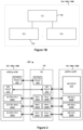
- Fig. 1B depicts an example, distributed implementation of any one or more of the base stations 104, 106A, 106B.
- the base station 104, 106A, or 106B includes a centralized unit (CU) 172 and one or more distributed units (DUs) 174.
- the CU 172 includes processing hardware, such as one or more general-purpose processors (e.g. , CPUs) and a computer-readable memory storing machine-readable instructions executable on the general-purpose processor(s), and/or special-purpose processing units.
- the CU 172 can include the processing hardware 130 or 140 of Fig. 1A .
- the processing hardware can include a base station RRC controller (e.g., RRC controller 142) configured to manage or control one or more RRC configurations and/or RRC procedures when the base station (e.g., base station 106A) operates as an SN.
- a base station RRC controller e.g., RRC controller 142 configured to manage or control one or more RRC configurations and/or RRC procedures when the base station (e.g., base station 106A) operates as an SN.
- Each of the DUs 174 also includes processing hardware that can include one or more general-purpose processors (e.g. , CPUs) and computer-readable memory storing machine-readable instructions executable on the one or more general-purpose processors, and/or special-purpose processing units.
- the processing hardware can include a medium access control (MAC) controller configured to manage or control one or more MAC operations or procedures (e.g., a random access procedure), and a radio link control (RLC) controller configured to manage or control one or more RLC operations or procedures when the base station (e.g. , base station 106A) operates as an MN or an SN.
- the process hardware can also include a physical layer controller configured to manage or control one or more physical layer operations or procedures.
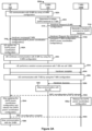
- Fig. 2 illustrates, in a simplified manner, an example dual active protocol stack (DAPS) 200 according to which the UE 102 can communicate with an eNB/ng-eNB or a gNB (e.g., one or more of the base stations 104, 106A, 106B).
- DAPS dual active protocol stack
- a physical layer (PHY) 202A of EUTRA provides transport channels to the EUTRA MAC sublayer 204A, which in turn provides logical channels to the EUTRA RLC sublayer 206A.
- the EUTRA RLC sublayer 206A in turn provides RLC channels to the EUTRA PDCP sublayer 208 and, in some cases, to the NR PDCP sublayer 210.
- the NR PHY 202B provides transport channels to the NR MAC sublayer 204B, which in turn provides logical channels to the NR RLC sublayer 206B.
- the NR RLC sublayer 206B in turn provides RLC channels to the NR PDCP sublayer 210.
- the UE 102 supports both the EUTRA and the NR stack as shown in Fig. 2 , to support handover between EUTRA and NR base stations and/or to support DC over EUTRA and NR interfaces. Further, as illustrated in Fig. 2 , the UE 102 can support layering of NR PDCP 210 over EUTRA RLC 206A.
- the EUTRA PDCP sublayer 208 and the NR PDCP sublayer 210 can provide SRBs to exchange RRC messages, for example.
- the EUTRA PDCP sublayer 208 and the NR PDCP sublayer 210 can provide DRBs to support data exchange.
- the wireless communication system 100 can provide the UE 102 with an MN-terminated bearer that uses EUTRA PDCP sublayer 208, or an MN-terminated bearer that uses NR PDCP sublayer 210.
- the wireless communication system 100 in various scenarios can also provide the UE 102 with an SN-terminated bearer, which uses only the NR PDCP sublayer 210.
- the MN-terminated bearer can be an MCG bearer or a split bearer.
- the SN-terminated bearer can be an SCG bearer or a split bearer.
- the MN-terminated bearer can be an SRB ( e.g., SRB1 or SRB2) or a DRB.
- the SN-terminated bearer can be an SRB or a DRB.
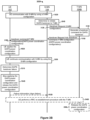
- the S-MN 104 sends 312A a Handover Request message to the T-MN 106B.
- the Handover Request message includes the S-MN configuration.
- the T-MN 106B generates 314A a handover command message for DAPS handover that includes a T-MN configuration including a DAPS power coordination configuration (e.g., a DAPS-PowerCoordinationInfo-r16 IE or DAPS-Configuration-r16 IE), includes the handover command message in a Handover Request Acknowledge message, and sends 316A the Handover Request Acknowledge message to the S-MN 104.
- a DAPS power coordination configuration e.g., a DAPS-PowerCoordinationInfo-r16 IE or DAPS-Configuration-r16 IE
- the S-MN 104 transmits 318A the handover command message to the UE 102.
- the handover command message also includes one or more random access configurations needed by the UE 102 to handover to the T-MN 106B, and in some implementations, includes additional fields or IEs, such as a mobility field or IE for a PCell of the T-MN 106B (e.g., mobilityControlInfo field, a reconfigurationWithSync field, MobilityControlInfo IE, a ReconfigurationWithSync IE), which can include some or all of the random access configurations.
- the T-MN 106B can include the DAPS power coordination configuration in the mobility field or IE.
- the T-MN 106B can include, in the handover command message, DAPS configuration(s) (e.g., daps-Config field(s) or a daps-HO field(s)) indicating particular DRB(s) as DAPS bearer(s).
- DAPS configuration(s) enables the UE 102 to use a DAPS (e.g. , DAPS 200) for the DAPS bearer(s) to communicate with the S-MN 104 (using configurations in the S-MN configuration) and T-MN 106B (using configurations in the T-MN configuration during and after a successful DAPS handover).
- the T-MN configuration includes multiple configuration parameters (e.g. , corresponding to physical layer, MAC layer, and/or RLC layer configurations) to configure radio resources.
- the UE 102 can use these multiple configuration parameters to communicate with the T-MN 106B via target PCell 126B.
- the multiple configuration parameters can configure zero, one, or more radio bearers, including SRB(s) ( e.g., SRB1, SRB2 and/or SRB4) and/or DRB(s).
- SRB(s) e.g., SRB1, SRB2 and/or SRB4
- DRB(s) e.g., DRB(s)
- the UE 102 can exchange RRC messages with the T-MN 106B via the SRB(s) ( i.e., SRB(s) for the target PCell), and communicate data with the T-MN 106B via the DRB(s).
- the MN configuration (i.e., the S-MN configuration or T-MN configuration) can include a CellGroupConfig IE.
- the MN configuration can be an RRCReconfiguration message, RRCReconfiguration-IEs, or the CellGroupConfig IE conforming to 3GPP TS 38.331, or an RRCConnectionReconfiguration message or RRCConnectionReconfiguration-IEs conforming to 3GPP TS 36.331.
- the MN configuration can include configurations in the CellGroupConfig IE, RRCReconfiguration-IEs, or RRCConnectionReconfiguration-IEs.
- the S-MN 104 consists of CU 172 and one or more DUs 174 as shown in Fig. 1B .
- the DU(s) 174 can generate the S-MN configuration or at least a portion of the S-MN configuration, and send the S-MN configuration (or portion) to the CU 172.
- the CU 172 can generate the remainder of the S-MN configuration if the DU 174 only generated a portion of the S-MN configuration.
- the DU(s) 174 can communicate with the UE 102 via the portion of the S-MN configuration, and the CU 172 can communicate with the UE 102 via the remainder of the S-MN configuration, in one implementation.
- the S-MN configuration (or portion) generated by the DU 174 can include one or more random access configurations, a physical downlink control channel (PDCCH) configuration, a PUCCH configuration, etc.
- the remainder of the S-MN configuration generated by the CU 172 can include an SRB configuration, a DRB configuration, a security configuration, and/or a measurement configuration.
- the DU 174 can include a cell group configuration (e.g., CellGroupConfig IE) in the S-MN configuration
- the CU 172 can include a radio bearer configuration ( RadioBearerConfig IE) in the S-MN configuration.
- RadioBearerConfig IE RadioBearerConfig IE
- the T-MN 106B consists of CU 172 and one or more DUs 174 as shown in Fig. 1B .
- the UE 102 can perform 322A the random access procedure with at least one of the DU(s) 174.
- the DU 174 generates some configurations (e.g., one or more random access configurations, a PDCCH configuration, a PUCCH configuration) and sends the configurations to the CU 172.
- the CU 172 can include other configurations (e.g. , an SRB configuration, a DRB configuration, a security configuration, and/or a measurement configuration) in the handover command message.
- the DU 174 can generate a cell group configuration (e.g., CellGroupConfig IE) and send the cell group configuration to the CU 172, which in turn can include a radio bearer configuration (e.g., RadioBearerConfig IE) and the cell group configuration in the handover command message.
- a cell group configuration e.g., CellGroupConfig IE
- RadioBearerConfig IE RadioBearerConfig IE
- the handover command message can be an RRCReconfiguration message
- the handover complete message can be an RRCReconfigurationComplete message
- the RRC reconfiguration message and the RRC reconfiguration complete message can be an RRCReconfiguration message and an RRCReconfigurationComplete message, respectively.
- the handover command message can be an RRCConnectionReconfiguration message
- the handover complete message can be an RRCConnectionReconfigurationComplete message
- the RRC reconfiguration message and the RRC reconfiguration complete message can be an RRCConnectionReconfiguration message and an RRCConnectionReconfigurationComplete message, respectively.
- a DAPS handover scenario 300B the base station 104 operates as an S-MN for the UE 102, and the base station 106B operates as a T-MN for the UE 102, similar to the DAPS handover scenario 300A of Fig. 3A .
- the UE 102 successfully performs a DAPS handover to the T-MN 106B prior to stopping and releasing the power coordination configuration
- the UE 102 fails to successfully perform the DAPS handover.
- the UE 102 communicates 302B data with the S-MN 104 by using an S-MN configuration, similar to event 302A. Later in time, the S-MN 104 determines 304B to initiate DAPS handover for the T-MN 106B and the UE 102 to communicate, similar to event 304A.
- the S-MN 104 After determining 304B to initiate DAPS handover, the S-MN 104 sends 312B a Handover Request message to the T-MN 106B, the T-MN 106B generates 314B a handover command message for DAPS handover that includes a T-MN configuration including a DAPS power coordination configuration, the T-MN 106B sends 316B the handover command message in a Handover Request Acknowledge message to the S-MN 104, and the S-MN 104 transmits 318B the handover command message to the UE 102, similar to events 312A, 314A, 316A, and 318A, respectively.
- the UE 102 In response to receiving 318B the handover command message, the UE 102 applies 352B the DAPS power coordination configuration, and continues 320B communicating with the S-MN 104 using the S-MN configuration while the UE 102 attempts to handover to the T-MN 106B in accordance with the handover command message, similar to events 352A and 320A, respectively.
- the UE 102 determines 321B a DAPS handover failure, i.e., the UE 102 fails to perform DAPS handover to the T-MN 106B using a random access procedure similar to 322A, e.g. , within a certain time duration.
- the UE 102 stops 354B applying the DAPS power coordination configuration and releases the DAPS power coordination configuration.
- the RRC controller 152 can send an indication to the PHY 202 of the UE 102, causing the PHY 202 to stop applying the DAPS power coordination configuration.
- the UE 102 releases the T-MN configuration received in event 318B in response to the determination at event 321B.
- the UE 102 can transmit 342B to the S-MN 104, e.g., via SRB1, a failure information message (e.g., FailureInformation ) indicating the DAPS handover failure with respect to the T-MN 106B.
- the UE 102 can then perform 348B an RRC re-establishment procedure on cell 126B or another cell with the T-MN 106B, in some implementations.
- the UE 102 If the radio link between the UE 102 and the S-MN 104 is not available, the UE 102 does not transmit the failure information message to the S-MN 104.
- the UE 102 transmits an RRC re-establishment request message to the T-MN 106B, which in turn transmits an RRC re-establishment message to the UE 102.
- the UE 102 can transmit an RRC re-establishment complete message to the T-MN 106B in response to the RRC re-establishment message.
- the UE 102 Because the UE 102 has stopped 354B applying the DAPS power coordination configuration and released the DAPS power coordination configuration, the UE 102 advantageously will not unnecessarily restrict its maximum uplink power according to the DAPS power coordination configuration (e.g. , CP1 and/or CP2) when communicating with the S-MN 104, such as when transmitting 342B the failure information message to the S-MNB 104, and/or when communicating with the T-MN 106B, such as during or after performing 348B the RRC re-establishment procedure with the T-MN 106B.
- the DAPS power coordination configuration e.g. , CP1 and/or CP2
- the T-MN 106B can release 356B the DAPS power coordination configuration some time after generating or transmitting the handover command message to the S-MN 104. In some implementations, the T-MN 106B can release the DAPS power coordination configuration if the UE 102 does not successfully handover to the T-MN 106B within a time duration. In other implementations, the T-MN 106B can release the DAPS power coordination configuration in response to the RRC re-establishment procedure.
- the UE 102 can perform the RRC re-establishment procedure with the S-MN 104 via cell 122 or cell 124 instead of with the T-MN 106B.
- the UE 102 has stopped 354B applying the DAPS power coordination configuration and released the DAPS power coordination configuration, the UE 102 is also not restricted by the DAPS power coordination configuration parameter CP1 during and after performing the RRC re-establishment procedure with the S-MN 104.
- the RRC re-establishment request message, the RRC re-establishment message, and the RRC re-establishment complete message can be an RRCReestablishmentRequest message, an RRCReestablishment message, and an RRCReestablishmentComplete message, respectively.
- the RRC re-establishment request message, the RRC re-establishment message, and the RRC re-establishment complete message can be an RRCConnectionReestablishmentRequest message, an RRCConnectionReestablishment message, and an RRCConnectionReestablishmentComplete message, respectively.
- Figs. 3A and 3B depict the DAPS handover scenarios 300A and 300B occurring between two base stations (e.g. , the base stations 104, 106B) with respect to the UE 102
- the DAPS handover scenarios 300A and 300B can be carried out within a single base station (e.g., the S-MN 104) with respect to the UE 102.
- messages exchanged between the S-MN 104 and T-MN 106B e.g. , events 312A, 312B, 316A, 316B, 328A
- the events performed or otherwise involving the T-MN 106B e.g. , events 314A, 314B, 322A, 324A, 326A, 332A, 356A, 356B, 334A, 348B
- the S-MN 104 e.g., events 314A, 314B, 322A, 324A, 326A, 332A, 356A, 356
- the MN 104 receives the DAPS power coordination configuration from the T-SN 106B in the SN Addition Request Acknowledge message.
- the T-SN 106B can generate and include the DAPS power coordination configuration (e.g., a DAPS-PowerCoordinationInfo-r16 IE or DAPS-Configuration-r16 IE) in the T-SN configuration or in the SN Addition Request Acknowledge message.
- the S-SN 106A can generate and send the DAPS power coordination configuration to the MN 104 in the SN Change Required message or in an SN Modification Request Acknowledge message.
- the MN 104 after receiving 452B the failure information message from the UE 102 in an RRC container message (e.g., ULInformationTransferMRDC ), the MN 104 extracts the failure information message from the RRC container message and sends 453B the failure information message to the S-SN 106A in an RRC Transfer message. In another implementation, the MN 104 does not send the failure information message to the S-SN 106A.
- an RRC container message e.g., ULInformationTransferMRDC
- the UE 102 can transmit, to the S-SN 106A via the available SRB, the failure information message indicating the DAPS PSCell change failure with respect to the T-SN 106B at event 455B.
- the S-SN 106A can send an SN message (e.g., SN Modification Required message) to the MN 104 to inform the MN 104 of the DAPS PSCell change failure.
- the UE 102 can transmit 472B the SCG failure information message to the MN 104 to inform the MN 104 of the DAPS PSCell change failure.
- the UE 102 Because the UE 102 has stopped 454B applying the DAPS power coordination configuration and released the DAPS power coordination configuration, the UE 102 advantageously will not unnecessarily restrict its maximum uplink power according to the DAPS power coordination configuration when communicating with the MN 104, such as when transmitting the failure information message or the SCG failure information message, and/or when communicating with the S-SN 106A, such as when transmitting the failure information message.
- the T-SN 106B can release 456B the DAPS power coordination configuration after generating or transmitting the T-SN configuration to the MN 104. In some implementations, the T-SN 106B can release the DAPS power coordination configuration if the UE 102 does not successfully perform DAPS PSCell change to the T-SN 106B within a time duration. In other implementations, the MN 104 can release the DAPS power coordination configuration in response to receiving 452B the failure information message or in response to receiving the SN message from the S-SN 106A informing the DAPS PSCell change failure.
- Figs. 4A and 4B depict the DAPS PSCell change scenarios 400A and 400B occurring between two SNs ( e.g., the base stations 106A, 106B) with respect to the UE 102
- the DAPS PSCell change scenarios 400A and 400B can be carried out within a single SN ( e.g., the S-SN 106A) with respect to the UE 102.
- messages exchanged between the MN 104 and T-SN 106B e.g., events 412A, 416A, 419A
- events performed or otherwise involving the T-SN 106B e.g., 414A, 419A, 422A, 426A, 432A, 456A, 434A, 460B
- S-SN 106A e.g., S-SN 106A.
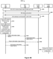
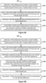
- Fig. 5A is a flow diagram depicting an example method 500A implemented in a user device (e.g., UE 102) for applying and later releasing a DAPS power coordination configuration when switching from a source base station (e.g., S-MN 104, S-SN 106A) to a target base station (e.g., T-MN 106B, T-SN 106B).
- a source base station e.g., S-MN 104, S-SN 106A
- T-MN 106B e.g., T-SN 106B
- a user device receives, from a source base station, a first message including a DAPS power coordination configuration for DAPS operation with the source base station and a target station ( e.g., in any one of events 318A, 417A).
- the user device e.g., via DAPS 200
- the first message can be a handover command message or an RRC container message, in some implementations.
- the user device applies the DAPS power coordination configuration for communicating with the source base station and the target base station ( e.g., in any one of events 352A, 452A).
- the user device restricts respective maximum total transmission uplink power when communicating with the source base station and the target base station.
- the user device receives, from the target base station, a second message indicating release of the DAPS operation (e.g., in any one of events 332A, 432A). Accordingly, the target base station explicitly provides the second message to the user device to indicate that the user device should stop communicating with the source base station, and continue communicating with the target base station.
- the second message can be an RRC reconfiguration message, in some implementations.
- the user device disconnects from the source base station ( i.e., stops communicating with the source base station), stops applying the DAPS power coordination configuration, and releases the DAPS power coordination configuration (e.g., in any one of events 336A, 354A, 436A, 454A).
- the user device will not continue to restrict its maximum uplink power according to the DAPS power coordination configuration when communicating with the target base station after successfully performing the DAPS handover or DAPS PSCell change. Because DAPS power restrictions have been removed, the user device can increase its uplink power up to its maximum uplink power, and the user device can reduce the chances of radio link failure with the target base station.
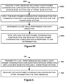
- Fig. 5B is a flow diagram depicting another example method 500B implemented in a user device (e.g., UE 102) for applying and later releasing a DAPS power coordination configuration when switching from a source base station (e.g., S-MN 104, S-SN 106A) to a target station (e.g., T-MN 106B, T-SN 106B).
- a source base station e.g., S-MN 104, S-SN 106A
- T-MN 106B e.g., T-MN 106B, T-SN 106B
- the user device releases the DAPS power coordination configuration in response to an explicit message (e.g., RRC reconfiguration message) from the target base station
- the UE 102 releases the DAPS power coordination configuration after performing a random access procedure with the target base station.
- a user device receives, from a source base station, a first message including a DAPS power coordination configuration for DAPS operation with the source base station and a target station ( e.g., in any one of events 318A, 417A), similar to block 502A.
- the user device applies the DAPS power coordination configuration for communicating with the source base station and the target base station ( e.g., in any one of events 352A, 452A), similar to block 504A.
- the user device performs a random access procedure with the target base station in response to the first message ( e.g., in any one of events 322A, 422A).
- the user device stops applying the DAPS power coordination configuration and releases the DAPS power coordination configuration ( e.g., in any one of events 354A, 454A).
- the user device receives a second message indicating release of the DAPS operation (e.g., event 332A or 432A), similar to block 506A.
- a second message indicating release of the DAPS operation e.g., event 332A or 432A
- Fig. 5C is a flow diagram depicting another example method 500C implemented in a user device (e.g., UE 102) for applying and releasing a DAPS power coordination configuration when switching from a source base station (e.g., S-MN 104, S-SN 106A) to a target station (e.g., T-MN 106B, T-SN 106B).
- a source base station e.g., S-MN 104, S-SN 106A
- T-MN 106B e.g., T-MN 106B
- T-SN 106B e.g., T-SN 106B
- the user device determines a failure (e.g., a radio link failure) while performing the DAPS operation (e.g., in any one of events 321B, 421B). That is, the user device fails to perform either DAPS handover or DAPS PSCell change to the target base station.
- a failure e.g., a radio link failure
- the user device stops applying the DAPS power coordination configuration and releases the DAPS power coordination configuration (e.g., in any one of events 354B, 454B).
- the user device later performs an RRC re-establishment procedure with the source base station or the target source base station for example, the user device is not restricted by the maximum uplink power as designated in the DAPS power coordination configuration during and after performing the RRC re-establishment procedure with the source base station or the target base station. Because the user device can increase its uplink power beyond the maximum uplink power indicated in the DAPS power coordination configuration, the user device can decrease the chances of radio link failure with the source base station or the target base station.
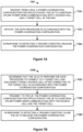
- Fig. 6 is a flow diagram depicting an example method 600 implemented in a RAN (e.g., RAN 105) for providing a DAPS power coordination configuration to a user device (e.g., UE 102) described with respect to Figs. 5A, 5B , and 5C , and later releasing the DAPS power coordination configuration.
- a RAN e.g., RAN 105
- UE 102 e.g., UE 102
- Fig. 7A illustrates an example method 700A for managing a power coordination configuration when performing a DAPS procedure, which can be implemented in a suitable UE such as the UE 102.
- the UE receives, from a RAN, a power coordination configuration for application by the UE to constrain uplink power when communicating with a source cell and a target cell of the RAN (e.g., events 318A, 318B, 460A, 460B).
- a power coordination configuration for application by the UE to constrain uplink power when communicating with a source cell and a target cell of the RAN (e.g., events 318A, 318B, 460A, 460B).
- the UE in response to detecting a trigger condition, releases the power coordination configuration (e.g., events 354A, 354B, 454A, 454B).
- the UE releases the power coordination configuration when the UE connects to the target cell when performing the DAPS procedure.
- the UE releases the power coordination configuration when the UE receives, from the RAN via the target cell, an indication the UE is to release the power coordination configuration.
- the UE releases the power coordination configuration when the UE fails to connect to the target cell when performing the DAPS procedure.
- the user device can operate as an internet-of-things (IoT) device or a mobile-internet device (MID).
- IoT internet-of-things
- MID mobile-internet device
- the user device can include one or more general-purpose processors, a computer-readable memory, a user interface, one or more network interfaces, one or more sensors, etc.
- Modules may can be software modules (e.g., code, or machine-readable instructions stored on non-transitory machine-readable medium) or hardware modules.
- a hardware module is a tangible unit capable of performing certain operations and may be configured or arranged in a certain manner.
- a hardware module can comprise dedicated circuitry or logic that is permanently configured (e.g., as a special-purpose processor, such as a field programmable gate array (FPGA) or an application-specific integrated circuit (ASIC), a digital signal processor (DSP), etc.) to perform certain operations.
- FPGA field programmable gate array
- ASIC application-specific integrated circuit
- DSP digital signal processor
Landscapes
- Engineering & Computer Science (AREA)
- Computer Networks & Wireless Communication (AREA)
- Signal Processing (AREA)
- Mobile Radio Communication Systems (AREA)
Claims (10)
- Procédé réalisé par un équipement utilisateur, UE, de gestion d'une configuration de coordination de puissance lors de la réalisation d'une procédure de pile de protocoles doublement active, DAPS, le procédé comprenant :la réception (318B), par l'UE et provenant d'une station de base source d'un réseau d'accès radio, RAN, d'une configuration de coordination de puissance à appliquer par l'UE pour contraindre une puissance de liaison montante lors de la communication avec une cellule source et une cellule cible du RAN ;l'initiation (352B), par l'UE, de la procédure DAPS conformément à la configuration de coordination de puissance ; eten réponse à la détection d'un échec lors de la réalisation de la procédure DAPS, la libération (354B), par l'UE, de la configuration de coordination de puissance.
- Procédé selon la revendication 1, dans lequel l'échec comporte :
un échec de l'UE à se connecter à la cellule cible lors de la réalisation de la procédure DAPS. - Procédé selon la revendication 2, comprenant également :
la transmission, par l'UE au RAN par l'intermédiaire de la station de base source, d'une indication du fait que l'UE a échoué à se connecter à la cellule cible. - Procédé selon l'une quelconque des revendications précédentes, comprenant également :
le rétablissement d'une connexion radio entre l'UE et le RAN. - Procédé selon l'une quelconque des revendications précédentes, dans lequel :
la procédure DAPS est l'une d'une procédure de transfert DAPS et d'une procédure de changement de cellule primaire secondaire, PSCell, DAPS. - UE (102) comprenant du matériel de traitement configuré pour mettre en œuvre un procédé selon l'une quelconque des revendications 1 à 5.
- Procédé réalisé par une station de base source dans un RAN pour gérer une configuration de coordination de puissance lors de la réalisation d'une procédure DAPS avec un UE, le procédé comprenant :la détermination (304B), par la station de base source, du fait que l'UE doit réaliser la procédure DAPS pour se connecter à une cellule cible et se déconnecter d'une cellule source après s'être connecté à la cellule cible conformément à la configuration de coordination de puissance ;la transmission (318B), par la station de base source à l'UE, de la configuration de coordination de puissance à appliquer par l'UE pour contraindre une puissance de liaison montante lors de la communication avec la cellule source et la cellule cible ; eten réponse à la réception d'un message d'informations provenant de l'UE concernant un échec lors de la réalisation de la procédure DAPS, le déclenchement de la libération par la cellule source de la configuration de coordination de puissance.
- Procédé selon la revendication 7, dans lequel la station de base source transmet la configuration de coordination de puissance à l'UE dans un message de commande de transfert ou un message de conteneur RRC.
- Procédé selon l'une quelconque des revendications 7 à 8, dans lequel :
la procédure DAPS est l'une d'une procédure de transfert DAPS et d'une procédure de changement de cellule primaire secondaire, PSCell, DAPS. - Station de base (104) comprenant du matériel de traitement configurée pour mettre en œuvre un procédé selon l'une quelconque des revendications 7 à 9.
Applications Claiming Priority (3)
| Application Number | Priority Date | Filing Date | Title |
|---|---|---|---|
| US202063028421P | 2020-05-21 | 2020-05-21 | |
| US202063080835P | 2020-09-21 | 2020-09-21 | |
| PCT/US2021/033137 WO2021236755A1 (fr) | 2020-05-21 | 2021-05-19 | Gestion de configurations daps |
Publications (2)
| Publication Number | Publication Date |
|---|---|
| EP4140185A1 EP4140185A1 (fr) | 2023-03-01 |
| EP4140185B1 true EP4140185B1 (fr) | 2025-07-02 |
Family
ID=76444597
Family Applications (2)
| Application Number | Title | Priority Date | Filing Date |
|---|---|---|---|
| EP21732681.8A Pending EP4136880A1 (fr) | 2020-05-21 | 2021-05-19 | Configurations de gestion pour rétablir une connexion radio |
| EP21733014.1A Active EP4140185B1 (fr) | 2020-05-21 | 2021-05-19 | Gestion de configuration daps |
Family Applications Before (1)
| Application Number | Title | Priority Date | Filing Date |
|---|---|---|---|
| EP21732681.8A Pending EP4136880A1 (fr) | 2020-05-21 | 2021-05-19 | Configurations de gestion pour rétablir une connexion radio |
Country Status (4)
| Country | Link |
|---|---|
| US (2) | US12574815B2 (fr) |
| EP (2) | EP4136880A1 (fr) |
| CN (2) | CN116134891B (fr) |
| WO (2) | WO2021236755A1 (fr) |
Families Citing this family (11)
| Publication number | Priority date | Publication date | Assignee | Title |
|---|---|---|---|---|
| EP4136880A1 (fr) * | 2020-05-21 | 2023-02-22 | Google LLC | Configurations de gestion pour rétablir une connexion radio |
| CN115699892A (zh) * | 2020-06-10 | 2023-02-03 | 株式会社Ntt都科摩 | 终端 |
| WO2022013698A2 (fr) | 2020-07-13 | 2022-01-20 | Lenovo (Singapore) Pte. Ltd. | Indication d'une demande de ressources de liaison latérale |
| CN116235550B (zh) * | 2020-07-31 | 2025-02-11 | 中兴通讯股份有限公司 | 用于增强新无线的集成接入和回程的移动稳健性的方法和设备 |
| EP4260605A4 (fr) * | 2020-12-08 | 2024-12-04 | Lenovo (Beijing) Limited | Procédés et appareil pour un mécanisme de reprise sur défaillance daps et un mécanisme mro pour des procédures cho et daps |
| WO2022269567A1 (fr) * | 2021-06-24 | 2022-12-29 | Telefonaktiebolaget Lm Ericsson (Publ) | Signalisation inter-nœuds pour la configuration d'un rapport de transfert intercellulaire réussi |
| US12418787B2 (en) * | 2021-06-28 | 2025-09-16 | Mediatek Inc. | Apparatuses and methods for simultaneous reception or transmission associated with dual subscriber numbers using a single radio frequency (RF) device |
| KR20230008431A (ko) * | 2021-07-07 | 2023-01-16 | 삼성전자주식회사 | 이동통신 시스템에서 조건 기반 daps 핸드오버를 수행하는 방법 및 장치 |
| WO2023081298A2 (fr) * | 2021-11-03 | 2023-05-11 | Ofinno, Llc | Informations de configuration pour multiconnectivité |
| EP4449777A4 (fr) * | 2022-07-01 | 2025-01-29 | ZTE Corporation | Transfert intercellulaire à double pile de protocoles active |
| WO2024014997A1 (fr) * | 2022-07-14 | 2024-01-18 | Telefonaktiebolaget Lm Ericsson (Publ) | Procédés pour améliorer un transfert intercellulaire et une double connectivité pour une économie d'énergie de réseau |
Family Cites Families (35)
| Publication number | Priority date | Publication date | Assignee | Title |
|---|---|---|---|---|
| MY183911A (en) * | 2013-05-10 | 2021-03-17 | Ericsson Telefon Ab L M | Bearer configuration signaling |
| MX381372B (es) | 2015-07-31 | 2025-03-12 | Nec Corp | Estación base y método de la misma. |
| US10893455B2 (en) * | 2016-04-01 | 2021-01-12 | Telefonaktiebolaget Lm Ericsson (Publ) | Handover in a wireless communication network with network slices |
| US11166243B2 (en) * | 2016-09-29 | 2021-11-02 | Apple Inc. | Mobile terminal devices and methods for apportioning uplink transmission power in mobile communication devices |
| US12587908B2 (en) | 2017-01-04 | 2026-03-24 | Sony Group Corporation | Handover of terminal between nodes supporting two rats |
| US10292081B2 (en) * | 2017-02-03 | 2019-05-14 | Lg Electronics Inc. | Method and apparatus for performing partial handover for continuous data transmission in wireless communication system |
| US10980077B2 (en) * | 2017-04-01 | 2021-04-13 | Lg Electronics Inc. | Method for performing MCG recovery in dual connectivity in wireless communication system and a device therefor |
| KR20200013056A (ko) | 2017-06-15 | 2020-02-05 | 콘비다 와이어리스, 엘엘씨 | 업링크 송신 전력 제어 |
| CN109429276B (zh) * | 2017-06-30 | 2021-03-30 | 华为技术有限公司 | 通信方法及装置 |
| US10973069B2 (en) * | 2017-08-07 | 2021-04-06 | Lg Electronics Inc. | Method and apparatus for keeping DC configuration |
| US11026291B2 (en) | 2017-09-29 | 2021-06-01 | Samsung Electronics Co., Ltd. | Method and user equipment for handling user plane in dual connectivity in wireless communication system |
| CN111164998B (zh) * | 2017-11-29 | 2025-06-17 | Oppo广东移动通信有限公司 | 重建rrc连接的方法、终端和存储介质 |
| EP3586469B1 (fr) | 2018-01-09 | 2020-12-02 | Ofinno, LLC | Processus de couche physique et mac dans un dispositif sans fil |
| US11438812B2 (en) * | 2018-07-10 | 2022-09-06 | Qualcomm Incorporated | Performing a combination of handover techniques |
| CN112806081B (zh) | 2018-10-02 | 2023-08-18 | 鸿颖创新有限公司 | 配置用户设备交换侧链路分组的方法和用户设备 |
| US11190997B2 (en) * | 2019-03-27 | 2021-11-30 | Lg Electronics Inc. | Method and apparatus for mobility in wireless communication system |
| CN113940113B (zh) * | 2019-05-03 | 2023-12-29 | Lg电子株式会社 | 针对无线通信系统中的无线电资源管理的方法和设备 |
| US11438813B2 (en) * | 2019-06-04 | 2022-09-06 | Qualcomm Incorporated | Enhanced user equipment capability exchange during handover |
| GB2590142B (en) | 2019-10-04 | 2022-10-12 | Samsung Electronics Co Ltd | Capability coordination for mobility with DAPS |
| US12262266B2 (en) * | 2019-11-01 | 2025-03-25 | Telefonaktiebolaget Lm Ericsson (Publ) | Dual active protocol stack handover reports |
| EP4055897B1 (fr) * | 2019-11-07 | 2024-07-17 | Ofinno, LLC | Accès aléatoire sur de multiples empilements de protocoles actifs |
| EP4008130B1 (fr) * | 2020-01-06 | 2024-10-02 | Samsung Electronics Co., Ltd. | Procédé et appareil pour configurer un repli pour chaque porteuse lorsque le transfert daps échoue dans un système de communication mobile de prochaine génération |
| US20230108496A1 (en) * | 2020-01-31 | 2023-04-06 | Telefonaktiebolaget Lm Ericsson (Publ) | Triggering a Subsequent Handover during a Dual-Active Protocol Stack Handover |
| WO2021159371A1 (fr) * | 2020-02-13 | 2021-08-19 | Oppo广东移动通信有限公司 | Procédé de traitement de commutation et dispositif terminal |
| EP3981217A4 (fr) * | 2020-02-13 | 2022-08-03 | Google LLC | Fonctionnement de pile de protocoles à double action pour transfert et changement de pscell |
| CN113286331B (zh) * | 2020-02-19 | 2022-08-26 | 华为技术有限公司 | 重建立的方法和通信装置 |
| US11950156B2 (en) * | 2020-03-24 | 2024-04-02 | Qualcomm Incorporated | Techniques for sharing transmission power during handover in wireless communications |
| CN115428576A (zh) * | 2020-04-22 | 2022-12-02 | 三星电子株式会社 | 无线通信系统中的用于在配置dap切换时处理lbt失败指示符的方法及装置 |
| KR20230005277A (ko) * | 2020-04-30 | 2023-01-09 | 구글 엘엘씨 | 핸드오버 실패 시나리오에서 네트워크 최적화 관리 |
| US20230189110A1 (en) * | 2020-05-12 | 2023-06-15 | Lenovo (Beijing) Ltd. | Method and apparatus for an enhanced failure report mechanism for master cell group and secondary cell group |
| CN113677040B (zh) * | 2020-05-13 | 2025-09-05 | 夏普株式会社 | 无线链路失败恢复方法及对应的用户设备 |
| EP4136880A1 (fr) * | 2020-05-21 | 2023-02-22 | Google LLC | Configurations de gestion pour rétablir une connexion radio |
| EP4449777A4 (fr) * | 2022-07-01 | 2025-01-29 | ZTE Corporation | Transfert intercellulaire à double pile de protocoles active |
| CN120642376A (zh) * | 2023-02-13 | 2025-09-12 | 三星电子株式会社 | 无线通信系统中用于处理musim操作中的临时ue能力改变的方法和装置 |
| US20240430766A1 (en) * | 2023-06-26 | 2024-12-26 | Samsung Electronics Co., Ltd. | Method and system for managing source cell connection during a dual active protocol stack (daps) handover |
-
2021
- 2021-05-19 EP EP21732681.8A patent/EP4136880A1/fr active Pending
- 2021-05-19 CN CN202180059290.5A patent/CN116134891B/zh active Active
- 2021-05-19 WO PCT/US2021/033137 patent/WO2021236755A1/fr not_active Ceased
- 2021-05-19 WO PCT/US2021/033129 patent/WO2021236750A1/fr not_active Ceased
- 2021-05-19 CN CN202180060819.5A patent/CN116134892A/zh active Pending
- 2021-05-19 US US17/926,561 patent/US12574815B2/en active Active
- 2021-05-19 EP EP21733014.1A patent/EP4140185B1/fr active Active
- 2021-05-19 US US17/926,548 patent/US20230199578A1/en active Pending
Also Published As
| Publication number | Publication date |
|---|---|
| US12574815B2 (en) | 2026-03-10 |
| EP4140185A1 (fr) | 2023-03-01 |
| CN116134891A (zh) | 2023-05-16 |
| CN116134891B (zh) | 2025-05-16 |
| CN116134892A (zh) | 2023-05-16 |
| US20230199578A1 (en) | 2023-06-22 |
| WO2021236750A1 (fr) | 2021-11-25 |
| US20230199579A1 (en) | 2023-06-22 |
| EP4136880A1 (fr) | 2023-02-22 |
| WO2021236755A1 (fr) | 2021-11-25 |
Similar Documents
| Publication | Publication Date | Title |
|---|---|---|
| EP4140185B1 (fr) | Gestion de configuration daps | |
| US20250267761A1 (en) | Dual active protocol stack operation for handover and pscell change | |
| US12219419B2 (en) | Conditional handover management | |
| EP4094537B1 (fr) | Gestion de configuration conditionnelle lorsqu'une cellule secondaire n'est pas disponible | |
| CN115918156B (zh) | 在切换失败场景中管理网络优化 | |
| US20240334266A1 (en) | Managing mcg fast recovery | |
| US12328628B2 (en) | Configuration handling at a user device | |
| US20220386191A1 (en) | Conditional full configuration and conditional delta configuration | |
| CN115336323A (zh) | 分布式基站中的有条件配置 | |
| TWI782399B (zh) | 在雙連接場景中管理條件組態 | |
| WO2021202216A1 (fr) | Fonctionnement de pile de protocoles à double action et configuration complète | |
| CN115486124A (zh) | 在有条件过程中管理无条件过程 |
Legal Events
| Date | Code | Title | Description |
|---|---|---|---|
| STAA | Information on the status of an ep patent application or granted ep patent |
Free format text: STATUS: UNKNOWN |
|
| STAA | Information on the status of an ep patent application or granted ep patent |
Free format text: STATUS: THE INTERNATIONAL PUBLICATION HAS BEEN MADE |
|
| PUAI | Public reference made under article 153(3) epc to a published international application that has entered the european phase |
Free format text: ORIGINAL CODE: 0009012 |
|
| STAA | Information on the status of an ep patent application or granted ep patent |
Free format text: STATUS: REQUEST FOR EXAMINATION WAS MADE |
|
| 17P | Request for examination filed |
Effective date: 20221121 |
|
| AK | Designated contracting states |
Kind code of ref document: A1 Designated state(s): AL AT BE BG CH CY CZ DE DK EE ES FI FR GB GR HR HU IE IS IT LI LT LU LV MC MK MT NL NO PL PT RO RS SE SI SK SM TR |
|
| DAV | Request for validation of the european patent (deleted) | ||
| DAX | Request for extension of the european patent (deleted) | ||
| GRAP | Despatch of communication of intention to grant a patent |
Free format text: ORIGINAL CODE: EPIDOSNIGR1 |
|
| STAA | Information on the status of an ep patent application or granted ep patent |
Free format text: STATUS: GRANT OF PATENT IS INTENDED |
|
| GRAJ | Information related to disapproval of communication of intention to grant by the applicant or resumption of examination proceedings by the epo deleted |
Free format text: ORIGINAL CODE: EPIDOSDIGR1 |
|
| INTG | Intention to grant announced |
Effective date: 20250128 |
|
| RIC1 | Information provided on ipc code assigned before grant |
Ipc: H04W 36/18 20090101ALI20250117BHEP Ipc: H04W 36/00 20090101AFI20250117BHEP |
|
| STAA | Information on the status of an ep patent application or granted ep patent |
Free format text: STATUS: REQUEST FOR EXAMINATION WAS MADE |
|
| GRAP | Despatch of communication of intention to grant a patent |
Free format text: ORIGINAL CODE: EPIDOSNIGR1 |
|
| STAA | Information on the status of an ep patent application or granted ep patent |
Free format text: STATUS: GRANT OF PATENT IS INTENDED |
|
| INTC | Intention to grant announced (deleted) | ||
| INTG | Intention to grant announced |
Effective date: 20250312 |
|
| GRAS | Grant fee paid |
Free format text: ORIGINAL CODE: EPIDOSNIGR3 |
|
| GRAA | (expected) grant |
Free format text: ORIGINAL CODE: 0009210 |
|
| STAA | Information on the status of an ep patent application or granted ep patent |
Free format text: STATUS: THE PATENT HAS BEEN GRANTED |
|
| AK | Designated contracting states |
Kind code of ref document: B1 Designated state(s): AL AT BE BG CH CY CZ DE DK EE ES FI FR GB GR HR HU IE IS IT LI LT LU LV MC MK MT NL NO PL PT RO RS SE SI SK SM TR |
|
| REG | Reference to a national code |
Ref country code: GB Ref legal event code: FG4D |
|
| REG | Reference to a national code |
Ref country code: CH Ref legal event code: EP |
|
| REG | Reference to a national code |
Ref country code: DE Ref legal event code: R096 Ref document number: 602021033373 Country of ref document: DE |
|
| REG | Reference to a national code |
Ref country code: IE Ref legal event code: FG4D |
|
| P01 | Opt-out of the competence of the unified patent court (upc) registered |
Free format text: CASE NUMBER: APP_31757/2025 Effective date: 20250701 |
|
| REG | Reference to a national code |
Ref country code: NL Ref legal event code: MP Effective date: 20250702 |
|
| PG25 | Lapsed in a contracting state [announced via postgrant information from national office to epo] |
Ref country code: PT Free format text: LAPSE BECAUSE OF FAILURE TO SUBMIT A TRANSLATION OF THE DESCRIPTION OR TO PAY THE FEE WITHIN THE PRESCRIBED TIME-LIMIT Effective date: 20251103 |
|
| PG25 | Lapsed in a contracting state [announced via postgrant information from national office to epo] |
Ref country code: NL Free format text: LAPSE BECAUSE OF FAILURE TO SUBMIT A TRANSLATION OF THE DESCRIPTION OR TO PAY THE FEE WITHIN THE PRESCRIBED TIME-LIMIT Effective date: 20250702 |
|
| REG | Reference to a national code |
Ref country code: AT Ref legal event code: MK05 Ref document number: 1810728 Country of ref document: AT Kind code of ref document: T Effective date: 20250702 |
|
| PG25 | Lapsed in a contracting state [announced via postgrant information from national office to epo] |
Ref country code: IS Free format text: LAPSE BECAUSE OF FAILURE TO SUBMIT A TRANSLATION OF THE DESCRIPTION OR TO PAY THE FEE WITHIN THE PRESCRIBED TIME-LIMIT Effective date: 20251102 |
|
| PG25 | Lapsed in a contracting state [announced via postgrant information from national office to epo] |
Ref country code: NO Free format text: LAPSE BECAUSE OF FAILURE TO SUBMIT A TRANSLATION OF THE DESCRIPTION OR TO PAY THE FEE WITHIN THE PRESCRIBED TIME-LIMIT Effective date: 20251002 |
|
| REG | Reference to a national code |
Ref country code: LT Ref legal event code: MG9D |
|
| PG25 | Lapsed in a contracting state [announced via postgrant information from national office to epo] |
Ref country code: AT Free format text: LAPSE BECAUSE OF FAILURE TO SUBMIT A TRANSLATION OF THE DESCRIPTION OR TO PAY THE FEE WITHIN THE PRESCRIBED TIME-LIMIT Effective date: 20250702 |
|
| PG25 | Lapsed in a contracting state [announced via postgrant information from national office to epo] |
Ref country code: FI Free format text: LAPSE BECAUSE OF FAILURE TO SUBMIT A TRANSLATION OF THE DESCRIPTION OR TO PAY THE FEE WITHIN THE PRESCRIBED TIME-LIMIT Effective date: 20250702 |
|
| PG25 | Lapsed in a contracting state [announced via postgrant information from national office to epo] |
Ref country code: HR Free format text: LAPSE BECAUSE OF FAILURE TO SUBMIT A TRANSLATION OF THE DESCRIPTION OR TO PAY THE FEE WITHIN THE PRESCRIBED TIME-LIMIT Effective date: 20250702 |
|
| PG25 | Lapsed in a contracting state [announced via postgrant information from national office to epo] |
Ref country code: GR Free format text: LAPSE BECAUSE OF FAILURE TO SUBMIT A TRANSLATION OF THE DESCRIPTION OR TO PAY THE FEE WITHIN THE PRESCRIBED TIME-LIMIT Effective date: 20251003 |
|
| PG25 | Lapsed in a contracting state [announced via postgrant information from national office to epo] |
Ref country code: CZ Free format text: LAPSE BECAUSE OF FAILURE TO SUBMIT A TRANSLATION OF THE DESCRIPTION OR TO PAY THE FEE WITHIN THE PRESCRIBED TIME-LIMIT Effective date: 20250702 Ref country code: SE Free format text: LAPSE BECAUSE OF FAILURE TO SUBMIT A TRANSLATION OF THE DESCRIPTION OR TO PAY THE FEE WITHIN THE PRESCRIBED TIME-LIMIT Effective date: 20250702 |
|
| PG25 | Lapsed in a contracting state [announced via postgrant information from national office to epo] |
Ref country code: LV Free format text: LAPSE BECAUSE OF FAILURE TO SUBMIT A TRANSLATION OF THE DESCRIPTION OR TO PAY THE FEE WITHIN THE PRESCRIBED TIME-LIMIT Effective date: 20250702 |
|
| PG25 | Lapsed in a contracting state [announced via postgrant information from national office to epo] |
Ref country code: PL Free format text: LAPSE BECAUSE OF FAILURE TO SUBMIT A TRANSLATION OF THE DESCRIPTION OR TO PAY THE FEE WITHIN THE PRESCRIBED TIME-LIMIT Effective date: 20250702 Ref country code: BG Free format text: LAPSE BECAUSE OF FAILURE TO SUBMIT A TRANSLATION OF THE DESCRIPTION OR TO PAY THE FEE WITHIN THE PRESCRIBED TIME-LIMIT Effective date: 20250702 |
|
| PG25 | Lapsed in a contracting state [announced via postgrant information from national office to epo] |
Ref country code: RS Free format text: LAPSE BECAUSE OF FAILURE TO SUBMIT A TRANSLATION OF THE DESCRIPTION OR TO PAY THE FEE WITHIN THE PRESCRIBED TIME-LIMIT Effective date: 20251002 |
|
| PG25 | Lapsed in a contracting state [announced via postgrant information from national office to epo] |
Ref country code: ES Free format text: LAPSE BECAUSE OF FAILURE TO SUBMIT A TRANSLATION OF THE DESCRIPTION OR TO PAY THE FEE WITHIN THE PRESCRIBED TIME-LIMIT Effective date: 20250702 |
|
| PG25 | Lapsed in a contracting state [announced via postgrant information from national office to epo] |
Ref country code: SM Free format text: LAPSE BECAUSE OF FAILURE TO SUBMIT A TRANSLATION OF THE DESCRIPTION OR TO PAY THE FEE WITHIN THE PRESCRIBED TIME-LIMIT Effective date: 20250702 |
|
| PG25 | Lapsed in a contracting state [announced via postgrant information from national office to epo] |
Ref country code: DK Free format text: LAPSE BECAUSE OF FAILURE TO SUBMIT A TRANSLATION OF THE DESCRIPTION OR TO PAY THE FEE WITHIN THE PRESCRIBED TIME-LIMIT Effective date: 20250702 |
|
| PG25 | Lapsed in a contracting state [announced via postgrant information from national office to epo] |
Ref country code: IT Free format text: LAPSE BECAUSE OF FAILURE TO SUBMIT A TRANSLATION OF THE DESCRIPTION OR TO PAY THE FEE WITHIN THE PRESCRIBED TIME-LIMIT Effective date: 20250702 |
|
| PG25 | Lapsed in a contracting state [announced via postgrant information from national office to epo] |
Ref country code: EE Free format text: LAPSE BECAUSE OF FAILURE TO SUBMIT A TRANSLATION OF THE DESCRIPTION OR TO PAY THE FEE WITHIN THE PRESCRIBED TIME-LIMIT Effective date: 20250702 Ref country code: SK Free format text: LAPSE BECAUSE OF FAILURE TO SUBMIT A TRANSLATION OF THE DESCRIPTION OR TO PAY THE FEE WITHIN THE PRESCRIBED TIME-LIMIT Effective date: 20250702 |