EP4140212B1 - Techniken zur wiederholung eines transportblocks unter verwendung von räumlichem multiplexen - Google Patents
Techniken zur wiederholung eines transportblocks unter verwendung von räumlichem multiplexen Download PDFInfo
- Publication number
- EP4140212B1 EP4140212B1 EP20931762.7A EP20931762A EP4140212B1 EP 4140212 B1 EP4140212 B1 EP 4140212B1 EP 20931762 A EP20931762 A EP 20931762A EP 4140212 B1 EP4140212 B1 EP 4140212B1
- Authority
- EP
- European Patent Office
- Prior art keywords
- dci message
- resource
- dci
- codeword
- repetition
- Prior art date
- Legal status (The legal status is an assumption and is not a legal conclusion. Google has not performed a legal analysis and makes no representation as to the accuracy of the status listed.)
- Active
Links
Images







Classifications
-
- H—ELECTRICITY
- H04—ELECTRIC COMMUNICATION TECHNIQUE
- H04B—TRANSMISSION
- H04B7/00—Radio transmission systems, i.e. using radiation field
- H04B7/02—Diversity systems; Multi-antenna system, i.e. transmission or reception using multiple antennas
- H04B7/04—Diversity systems; Multi-antenna system, i.e. transmission or reception using multiple antennas using two or more spaced independent antennas
-
- H—ELECTRICITY
- H04—ELECTRIC COMMUNICATION TECHNIQUE
- H04B—TRANSMISSION
- H04B7/00—Radio transmission systems, i.e. using radiation field
- H04B7/02—Diversity systems; Multi-antenna system, i.e. transmission or reception using multiple antennas
- H04B7/04—Diversity systems; Multi-antenna system, i.e. transmission or reception using multiple antennas using two or more spaced independent antennas
- H04B7/06—Diversity systems; Multi-antenna system, i.e. transmission or reception using multiple antennas using two or more spaced independent antennas at the transmitting station
- H04B7/0697—Diversity systems; Multi-antenna system, i.e. transmission or reception using multiple antennas using two or more spaced independent antennas at the transmitting station using spatial multiplexing
-
- H—ELECTRICITY
- H04—ELECTRIC COMMUNICATION TECHNIQUE
- H04L—TRANSMISSION OF DIGITAL INFORMATION, e.g. TELEGRAPHIC COMMUNICATION
- H04L1/00—Arrangements for detecting or preventing errors in the information received
- H04L1/08—Arrangements for detecting or preventing errors in the information received by repeating transmission, e.g. Verdan system
-
- H—ELECTRICITY
- H04—ELECTRIC COMMUNICATION TECHNIQUE
- H04L—TRANSMISSION OF DIGITAL INFORMATION, e.g. TELEGRAPHIC COMMUNICATION
- H04L1/00—Arrangements for detecting or preventing errors in the information received
- H04L1/12—Arrangements for detecting or preventing errors in the information received by using return channel
- H04L1/16—Arrangements for detecting or preventing errors in the information received by using return channel in which the return channel carries supervisory signals, e.g. repetition request signals
- H04L1/18—Automatic repetition systems, e.g. Van Duuren systems
- H04L1/1829—Arrangements specially adapted for the receiver end
- H04L1/1864—ARQ related signaling
-
- H—ELECTRICITY
- H04—ELECTRIC COMMUNICATION TECHNIQUE
- H04L—TRANSMISSION OF DIGITAL INFORMATION, e.g. TELEGRAPHIC COMMUNICATION
- H04L1/00—Arrangements for detecting or preventing errors in the information received
- H04L1/12—Arrangements for detecting or preventing errors in the information received by using return channel
- H04L1/16—Arrangements for detecting or preventing errors in the information received by using return channel in which the return channel carries supervisory signals, e.g. repetition request signals
- H04L1/18—Automatic repetition systems, e.g. Van Duuren systems
- H04L1/1867—Arrangements specially adapted for the transmitter end
- H04L1/189—Transmission or retransmission of more than one copy of a message
-
- H—ELECTRICITY
- H04—ELECTRIC COMMUNICATION TECHNIQUE
- H04L—TRANSMISSION OF DIGITAL INFORMATION, e.g. TELEGRAPHIC COMMUNICATION
- H04L1/00—Arrangements for detecting or preventing errors in the information received
- H04L1/12—Arrangements for detecting or preventing errors in the information received by using return channel
- H04L1/16—Arrangements for detecting or preventing errors in the information received by using return channel in which the return channel carries supervisory signals, e.g. repetition request signals
- H04L1/18—Automatic repetition systems, e.g. Van Duuren systems
- H04L1/1867—Arrangements specially adapted for the transmitter end
- H04L1/1896—ARQ related signaling
-
- H—ELECTRICITY
- H04—ELECTRIC COMMUNICATION TECHNIQUE
- H04L—TRANSMISSION OF DIGITAL INFORMATION, e.g. TELEGRAPHIC COMMUNICATION
- H04L5/00—Arrangements affording multiple use of the transmission path
- H04L5/0001—Arrangements for dividing the transmission path
- H04L5/0014—Three-dimensional division
- H04L5/0023—Time-frequency-space
- H04L5/0025—Spatial division following the spatial signature of the channel
-
- H—ELECTRICITY
- H04—ELECTRIC COMMUNICATION TECHNIQUE
- H04L—TRANSMISSION OF DIGITAL INFORMATION, e.g. TELEGRAPHIC COMMUNICATION
- H04L5/00—Arrangements affording multiple use of the transmission path
- H04L5/003—Arrangements for allocating sub-channels of the transmission path
- H04L5/0044—Allocation of payload; Allocation of data channels, e.g. PDSCH or PUSCH
Definitions
- aspects of the present disclosure generally relate to wireless communication and to techniques and apparatuses for repeating a transport block (TB) using spatial division multiplexing (SDM).
- TB transport block
- SDM spatial division multiplexing
- Wireless communication systems are widely deployed to provide various telecommunication services such as telephony, video, data, messaging, and broadcasts.
- Typical wireless communication systems may employ multiple-access technologies capable of supporting communication with multiple users by sharing available system resources (e.g., bandwidth, transmit power, and/or the like).
- multiple-access technologies include code division multiple access (CDMA) systems, time division multiple access (TDMA) systems, frequency-division multiple access (FDMA) systems, orthogonal frequency-division multiple access (OFDMA) systems, single-carrier frequency-division multiple access (SC-FDMA) systems, time division synchronous code division multiple access (TD-SCDMA) systems, and Long Term Evolution (LTE).
- LTE/LTE-Advanced is a set of enhancements to the Universal Mobile Telecommunications System (UMTS) mobile standard promulgated by the Third Generation Partnership Project (3GPP).
- UMTS Universal Mobile Telecommunications System
- a wireless communication network may include a number of base stations (BSs) that can support communication for a number of user equipment (UEs).
- a user equipment (UE) may communicate with a base station (BS) via the downlink and uplink.
- the downlink (or forward link) refers to the communication link from the BS to the UE
- the uplink (or reverse link) refers to the communication link from the UE to the BS.
- a BS may be referred to as a Node B, a gNB, an access point (AP), a radio head, a transmit receive point (TRP), a New Radio (NR) BS, a 5G Node B, and/or the like.
- New Radio which may also be referred to as 5G, is a set of enhancements to the LTE mobile standard promulgated by the Third Generation Partnership Project (3GPP).
- 3GPP Third Generation Partnership Project
- NR is designed to better support mobile broadband Internet access by improving spectral efficiency, lowering costs, improving services, making use of new spectrum, and better integrating with other open standards using orthogonal frequency division multiplexing (OFDM) with a cyclic prefix (CP) (CP-OFDM) on the downlink (DL), using CP-OFDM and/or SC-FDM (e.g., also known as discrete Fourier transform spread OFDM (DFT-s-OFDM)) on the uplink (UL), as well as supporting beamforming, multiple-input multiple-output (MIMO) antenna technology, and carrier aggregation.
- OFDM orthogonal frequency division multiplexing
- SC-FDM e.g., also known as discrete Fourier transform spread OFDM (DFT-s-OFDM)
- MIMO multiple-input multiple-output
- Document 3GPP TSG RAN WG1 meeting #96b R1-1905268 relates to discussion of rate matching methods for PDSCH reliability enhancement schemes with multi TRP panel.
- Document 3GPP TSG RAN WG1 #96 R1-1902812 relates to enhancements on multi-TRP/panel transmission.
- the invention is defined by a method of wireless communication performed by a user equipment according to claim 1, corresponding method of wireless communication performed by a base station according to claim 10 and the apparatuses according to claims 14 and 15. Further details are defined by the claims 2-9 and 11-13.
- Fig. 1 is a diagram illustrating a wireless network 100 in which aspects of the present disclosure may be practiced.
- the wireless network 100 may be an LTE network or some other wireless network, such as a 5G or NR network.
- the wireless network 100 may include a number of BSs 110 (shown as BS 110a, BS 110b, BS 110c, and BS 110d) and other network entities.
- a BS is an entity that communicates with user equipment (UEs) and may also be referred to as a base station, a NR BS, a Node B, a gNB, a 5G node B (NB), an access point, a transmit receive point (TRP), and/or the like.
- Each BS may provide communication coverage for a particular geographic area.
- the term "cell" can refer to a coverage area of a BS and/or a BS subsystem serving this coverage area, depending on the context in which the term is used.
- a BS may provide communication coverage for a macro cell, a pico cell, a femto cell, and/or another type of cell.
- a macro cell may cover a relatively large geographic area (e.g., several kilometers in radius) and may allow unrestricted access by UEs with service subscription.
- a pico cell may cover a relatively small geographic area and may allow unrestricted access by UEs with service subscription.
- a femto cell may cover a relatively small geographic area (e.g., a home) and may allow restricted access by UEs having association with the femto cell (e.g., UEs in a closed subscriber group (CSG)).
- a BS for a macro cell may be referred to as a macro BS.
- a BS for a pico cell may be referred to as a pico BS.
- a BS for a femto cell may be referred to as a femto BS or a home BS.
- a BS 110a may be a macro BS for a macro cell 102a
- a BS 110b may be a pico BS for a pico cell 102b
- a BS 110c may be a femto BS for a femto cell 102c.
- a BS may support one or multiple (e.g., three) cells.
- the terms "eNB”, “base station”, “NR BS”, “gNB”, “TRP”, “AP”, "node B", “5GNB”, and “cell” may be used interchangeably herein.
- a cell may not necessarily be stationary, and the geographic area of the cell may move according to the location of a mobile BS.
- the BSs may be interconnected to one another and/or to one or more other BSs or network nodes (not shown) in the wireless network 100 through various types of backhaul interfaces such as a direct physical connection, a virtual network, and/or the like using any suitable transport network.
- Wireless network 100 may also include relay stations.
- a relay station is an entity that can receive a transmission of data from an upstream station (e.g., a BS or a UE) and send a transmission of the data to a downstream station (e.g., a UE or a BS).
- a relay station may also be a UE that can relay transmissions for other UEs.
- a relay station 110d may communicate with macro BS 110a and a UE 120d in order to facilitate communication between BS 110a and UE 120d.
- a relay station may also be referred to as a relay BS, a relay base station, a relay, and/or the like.
- Wireless network 100 may be a heterogeneous network that includes BSs of different types, e.g., macro BSs, pico BSs, femto BSs, relay BSs, and/or the like. These different types of BSs may have different transmit power levels, different coverage areas, and different impacts on interference in wireless network 100.
- macro BSs may have a high transmit power level (e.g., 5 to 40 watts) whereas pico BSs, femto BSs, and relay BSs may have lower transmit power levels (e.g., 0.1 to 2 watts).
- a network controller 130 may couple to a set of BSs and may provide coordination and control for these BSs.
- Network controller 130 may communicate with the BSs via a backhaul.
- the BSs may also communicate with one another, e.g., directly or indirectly via a wireless or wireline backhaul.
- UEs 120 may be dispersed throughout wireless network 100, and each UE may be stationary or mobile.
- a UE may also be referred to as an access terminal, a terminal, a mobile station, a subscriber unit, a station, and/or the like.
- a UE may be a cellular phone (e.g., a smart phone), a personal digital assistant (PDA), a wireless modem, a wireless communication device, a handheld device, a laptop computer, a cordless phone, a wireless local loop (WLL) station, a tablet, a camera, a gaming device, a netbook, a smartbook, an ultrabook, a medical device or equipment, biometric sensors/devices, wearable devices (smart watches, smart clothing, smart glasses, smart wrist bands, smart jewelry (e.g., smart ring, smart bracelet)), an entertainment device (e.g., a music or video device, or a satellite radio), a vehicular component or sensor, smart meters/sensors, industrial manufacturing equipment, a global positioning system device, or any other suitable device that is configured to communicate via a wireless or wired medium.
- a cellular phone e.g., a smart phone
- PDA personal digital assistant
- WLL wireless local loop
- MTC and eMTC UEs include, for example, robots, drones, remote devices, sensors, meters, monitors, location tags, and/or the like, that may communicate with a base station, another device (e.g., remote device), or some other entity.
- a wireless node may provide, for example, connectivity for or to a network (e.g., a wide area network such as Internet or a cellular network) via a wired or wireless communication link.
- Some UEs may be considered Internet-of-Things (IoT) devices, and/or may be implemented as NB-IoT (narrowband internet of things) devices.
- Some UEs may be considered a Customer Premises Equipment (CPE).
- UE 120 may be included inside a housing that houses components of UE 120, such as processor components, memory components, and/or the like.
- any number of wireless networks may be deployed in a given geographic area.
- Each wireless network may support a particular radio access technology (RAT) and may operate on one or more frequencies.
- a RAT may also be referred to as a radio technology, an air interface, and/or the like.
- a frequency may also be referred to as a carrier, a frequency channel, and/or the like.
- Each frequency may support a single RAT in a given geographic area in order to avoid interference between wireless networks of different RATs.
- NR or 5G RAT networks may be deployed.
- two or more UEs 120 may communicate directly using one or more sidelink channels (e.g., without using a base station 110 as an intermediary to communicate with one another).
- the UEs 120 may communicate using peer-to-peer (P2P) communications, device-to-device (D2D) communications, a vehicle-to-everything (V2X) protocol (e.g., which may include a vehicle-to-vehicle (V2V) protocol, a vehicle-to-infrastructure (V2I) protocol, and/or the like), a mesh network, and/or the like).
- V2X vehicle-to-everything
- the UE 120 may perform scheduling operations, resource selection operations, and/or other operations described elsewhere herein as being performed by the base station 110.
- Fig. 1 is provided as an example. Other examples may differ from what is described with regard to Fig. 1 .
- Fig. 2 shows a block diagram of a design 200 of base station 110 and UE 120, which may be one of the base stations and one of the UEs in Fig. 1 .
- Base station 110 may be equipped with T antennas 234a through 234t
- UE 120 may be equipped with R antennas 252a through 252r, where in general T ⁇ 1 and R ⁇ 1.
- a transmit processor 220 may receive data from a data source 212 for one or more UEs, select one or more modulation and coding schemes (MCS) for each UE based at least in part on channel quality indicators (CQIs) received from the UE, process (e.g., encode and modulate) the data for each UE based at least in part on the MCS(s) selected for the UE, and provide data symbols for all UEs. Transmit processor 220 may also process system information (e.g., for semi-static resource partitioning information (SRPI) and/or the like) and control information (e.g., CQI requests, grants, upper layer signaling, and/or the like) and provide overhead symbols and control symbols.
- MCS modulation and coding schemes
- CQIs channel quality indicators
- Transmit processor 220 may also process system information (e.g., for semi-static resource partitioning information (SRPI) and/or the like) and control information (e.g., CQI requests, grants, upper layer signal
- Transmit processor 220 may also generate reference symbols for reference signals (e.g., the cell-specific reference signal (CRS)) and synchronization signals (e.g., the primary synchronization signal (PSS) and secondary synchronization signal (SSS)).
- a transmit (TX) multiple-input multiple-output (MIMO) processor 230 may perform spatial processing (e.g., precoding) on the data symbols, the control symbols, the overhead symbols, and/or the reference symbols, if applicable, and may provide T output symbol streams to T modulators (MODs) 232a through 232t. Each modulator 232 may process a respective output symbol stream (e.g., for OFDM and/or the like) to obtain an output sample stream.
- Each modulator 232 may further process (e.g., convert to analog, amplify, filter, and upconvert) the output sample stream to obtain a downlink signal.
- T downlink signals from modulators 232a through 232t may be transmitted via T antennas 234a through 234t, respectively.
- the synchronization signals can be generated with location encoding to convey additional information.
- antennas 252a through 252r may receive the downlink signals from base station 110 and/or other base stations and may provide received signals to demodulators (DEMODs) 254a through 254r, respectively.
- Each demodulator 254 may condition (e.g., filter, amplify, downconvert, and digitize) a received signal to obtain input samples.
- Each demodulator 254 may further process the input samples (e.g., for OFDM and/or the like) to obtain received symbols.
- a MIMO detector 256 may obtain received symbols from all R demodulators 254a through 254r, perform MIMO detection on the received symbols if applicable, and provide detected symbols.
- a receive processor 258 may process (e.g., demodulate and decode) the detected symbols, provide decoded data for UE 120 to a data sink 260, and provide decoded control information and system information to a controller/processor 280.
- a channel processor may determine reference signal received power (RSRP), received signal strength indicator (RSSI), reference signal received quality (RSRQ), channel quality indicator (CQI), and/or the like.
- RSRP reference signal received power
- RSSI received signal strength indicator
- RSRQ reference signal received quality indicator
- CQI channel quality indicator
- one or more components of UE 120 may be included in a housing.
- a transmit processor 264 may receive and process data from a data source 262 and control information (e.g., for reports comprising RSRP, RSSI, RSRQ, CQI, and/or the like) from controller/processor 280. Transmit processor 264 may also generate reference symbols for one or more reference signals. The symbols from transmit processor 264 may be precoded by a TX MIMO processor 266 if applicable, further processed by modulators 254a through 254r (e.g., for DFT-s-OFDM, CP-OFDM, and/or the like), and transmitted to base station 110.
- control information e.g., for reports comprising RSRP, RSSI, RSRQ, CQI, and/or the like
- Transmit processor 264 may also generate reference symbols for one or more reference signals.
- the symbols from transmit processor 264 may be precoded by a TX MIMO processor 266 if applicable, further processed by modulators 254a through 254r (e.g., for DFT-
- the uplink signals from UE 120 and other UEs may be received by antennas 234, processed by demodulators 232, detected by a MIMO detector 236 if applicable, and further processed by a receive processor 238 to obtain decoded data and control information sent by UE 120.
- Receive processor 238 may provide the decoded data to a data sink 239 and the decoded control information to controller/processor 240.
- Base station 110 may include communication unit 244 and communicate to network controller 130 via communication unit 244.
- Network controller 130 may include communication unit 294, controller/processor 290, and memory 292.
- Controller/processor 240 of base station 110, controller/processor 280 of UE 120, and/or any other component(s) of Fig. 2 may perform one or more techniques associated with repeating a TB using SDM, as described in more detail elsewhere herein.
- controller/processor 240 of base station 110, controller/processor 280 of UE 120, and/or any other component(s) of Fig. 2 may perform or direct operations of, for example, process 600 of Fig. 6 , process 700 of Fig. 7 , and/or other processes as described herein.
- Memories 242 and 282 may store data and program codes for base station 110 and UE 120, respectively.
- memory 242 and/or memory 282 may comprise a non-transitory computer-readable medium storing one or more instructions for wireless communication.
- the one or more instructions when executed by one or more processors of the base station 110 and/or the UE 120, may perform or direct operations of, for example, process 600 of Fig. 6 , process 700 of Fig. 7 , and/or other processes as described herein.
- a scheduler 246 may schedule UEs for data transmission on the downlink and/or uplink.
- UE 120 may include means for transmitting an indication that the UE 120 is capable of transmitting or receiving TB repetitions using SDM, means for receiving, and based at least in part on the indication, at least one DCI message that schedules a TB in a first resource and a repetition of the TB in a second resource, the first resource and the second resource at least partially overlapping in a time domain and a frequency domain, means for communicating the TB and the repetition of the TB using different antenna panels according to the at least one DCI message, and/or the like.
- such means may include one or more components of UE 120 described in connection with Fig. 2 , such as controller/processor 280, transmit processor 264, TX MIMO processor 266, MOD 254, antenna 252, DEMOD 254, MIMO detector 256, receive processor 258, and/or the like.
- base station 110 may include means for receiving an indication that a UE is capable of transmitting or receiving TB repetitions using SDM, means for transmitting, and based at least in part on receiving the indication, at least one DCI message that schedules a TB in a first resource and a repetition of the TB in a second resource, the first resource and the second resource at least partially overlapping in a time domain and a frequency domain, means for communicating the TB and the repetition of the TB according to the at least one DCI message, and/or the like.
- such means may include one or more components of base station 110 described in connection with Fig. 2 , such as antenna 234, DEMOD 232, MIMO detector 236, receive processor 238, controller/processor 240, transmit processor 220, TX MIMO processor 230, MOD 232, antenna 234, and/or the like.
- Fig. 2 is provided as an example. Other examples may differ from what is described with regard to Fig. 2 .
- Fig. 3 is a diagram illustrating an example logical architecture of a distributed RAN 300, according to aspects of the present disclosure.
- a 5G access node 305 may include an access node controller 310.
- the access node controller 310 may be a central unit (CU) of the distributed RAN 300.
- a backhaul interface to a 5G core network 315 may terminate at the access node controller 310.
- the 5G core network 315 may include a 5G control plane component 320 and a 5G user plane component 325 (e.g., a 5G gateway), and the backhaul interface for one or both of the 5G control plane and the 5G user plane may terminate at the access node controller 310.
- a backhaul interface to one or more neighbor access nodes 330 e.g., another 5G access node 305, an LTE access node, and/or the like
- the access node controller 310 may include and/or may communicate with one or more TRPs 335 (e.g., via an F1 Control (F1-C) interface and/or an F1 User (F1-U) interface).
- a TRP 335 may be a distributed unit (DU) of the distributed RAN 300.
- a TRP 335 may correspond to a base station 110 described above in connection with Fig. 1 .
- different TRPs 335 may be included in different base stations 110.
- multiple TRPs 335 may be included in a single base station 110.
- a base station 110 may include a CU (e.g., access node controller 310) and/or one or more DUs (e.g., one or more TRPs 335).
- a TRP 335 may be referred to as a cell, a panel, an antenna array, an array, and/or the like.
- a TRP 335 may be connected to a single access node controller 310 or to multiple access node controllers 310.
- a dynamic configuration of split logical functions may be present within the architecture of distributed RAN 300.
- a packet data convergence protocol (PDCP) layer, a radio link control (RLC) layer, a medium access control (MAC) layer, and/or the like may be configured to terminate at the access node controller 310 or at a TRP 335.
- PDCP packet data convergence protocol
- RLC radio link control
- MAC medium access control
- multiple TRPs 335 may transmit communications (e.g., the same communication or different communications) in the same transmission time interval (TTI) (e.g., a slot, a mini-slot, a subframe, a symbol, and/or the like) or different TTIs using different quasi-co-location (QCL) relationships (e.g., different spatial parameters, different transmission configuration indicator (TCI) states, different precoding parameters, different beamforming parameters, and/or the like).
- a TCI state may be used to indicate one or more QCL relationships.
- a TRP 335 may be configured to individually (e.g., using dynamic selection) or jointly (e.g., using joint transmission with one or more other TRPs 335) serve traffic to a UE 120.
- Fig. 3 is provided as an example. Other examples may differ from what was described with regard to Fig. 3 .
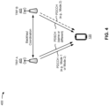
- Fig. 4 is a diagram illustrating an example 400 of multi-TRP communication (sometimes referred to as multi-panel communication), in accordance with various aspects of the present disclosure. As shown in Fig. 4 , multiple TRPs 405 may communicate with the same UE 120. A TRP 405 may correspond to a TRP 335 described above in connection with Fig. 3 .
- the multiple TRPs 405 may communicate with the same UE 120 in a coordinated manner (e.g., using coordinated multipoint transmissions and/or the like) to improve reliability, increase throughput, and/or the like.
- the TRPs 405 may coordinate such communications via an interface between the TRPs 405 (e.g., a backhaul interface, an access node controller 310, and/or the like).
- the interface may have a smaller delay and/or higher capacity when the TRPs 405 are co-located at the same base station 110 (e.g., when the TRPs 405 are different antenna arrays or panels of the same base station 110), and may have a larger delay and/or lower capacity (as compared to co-location) when the TRPs 405 are located at different base stations 110.
- the different TRPs 405 may communicate with the UE 120 using different QCL relationships (e.g., different TCI states), different demodulation reference signal (DMRS) ports, different layers (e.g., of a multi-layer communication), and/or the like.
- a single physical downlink control channel may be used to schedule downlink data communications for a single physical downlink shared channel (PDSCH).
- multiple TRPs 405 e.g., TRP A and TRP B
- TRP A and TRP B may transmit communications to the UE 120 on the same PDSCH.
- a communication may be transmitted using a single codeword with different spatial layers for different TRPs 405 (e.g., where one codeword maps to a first set of layers transmitted by a first TRP 405 and maps to a second set of layers transmitted by a second TRP 405).
- a communication may be transmitted using multiple codewords, where different codewords are transmitted by different TRPs 405 (e.g., using different sets of layers).
- different TRPs 405 may use different QCL relationships (e.g., different TCI states) for different DMRS ports corresponding to different layers.
- a first TRP 405 may use a first QCL relationship or a first TCI state for a first set of DMRS ports corresponding to a first set of layers
- a second TRP 405 may use a second (different) QCL relationship or a second (different) TCI state for a second (different) set of DMRS ports corresponding to a second (different) set of layers.
- a TCI state in downlink control information may indicate the first QCL relationship (e.g., by indicating a first TCI state) and the second QCL relationship (e.g., by indicating a second TCI state).
- the first and the second TCI states may be indicated using a TCI field in the DCI.
- the TCI field can indicate a single TCI state (for single-TRP transmission) or multiple TCI states (for multi-TRP transmission as discussed here) in this multi-TRP transmission mode (e.g., Mode 1).
- multiple PDCCHs may be used to schedule downlink data communications for multiple corresponding PDSCHs (e.g., one PDCCH for each PDSCH).
- a first PDCCH may schedule a first codeword to be transmitted by a first TRP 405, and a second PDCCH may schedule a second codeword to be transmitted by a second TRP 405.
- first DCI (e.g., transmitted by the first TRP 405) may schedule a first PDSCH communication associated with a first set of DMRS ports with a first QCL relationship (e.g., indicated by a first TCI state) for the first TRP 405, and second DCI (e.g., transmitted by the second TRP 405) may schedule a second PDSCH communication associated with a second set of DMRS ports with a second QCL relationship (e.g., indicated by a second TCI state) for the second TRP 405.
- DCI (e.g., having DCI format 1_0, DCI format 1_1, and/or the like) may indicate a corresponding TCI state for a TRP 405 corresponding to the DCI.
- the TCI field of a DCI indicates the corresponding TCI state (e.g., the TCI field of the first DCI indicates the first TCI state and the TCI field of the second DCI indicates the second TCI state).
- Fig. 4 is provided as an example. Other examples may differ from what is described with respect to Fig. 4 .
- a UE may use a plurality of antenna panels to perform concurrent (e.g., simultaneous) uplink transmissions or receive concurrent (e.g., simultaneous) downlink transmissions.
- the use of a plurality of antenna panels for concurrent transmissions may be referred to as a non-coherent joint transmission or spatial division multiplexing (SDM).
- SDM spatial division multiplexing
- TB repetition may be used to improve performance of transmissions, reliability of transmissions, and/or the like.
- wireless networks generally lack support for techniques to signal, configure, indicate, schedule, or otherwise enable TB repetition using SDM.
- a UE may transmit a capability report to a base station indicating that the UE supports transmitting or receiving TB repetitions using SDM, and the base station may provide the UE with a high-level configuration to enable TB repetitions using SDM (e.g., via radio resource control (RRC) signaling).
- RRC radio resource control
- the base station may then transmit, to the UE, a single DCI message, or a plurality of DCI messages, that schedule TB repetitions in resources that at least partially overlap in a time domain and a frequency domain, and the UE may communicate (e.g., transmit or receive) the TB repetitions according to the DCI message(s).
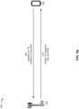
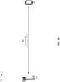
- Figs. 5A-5D are diagrams illustrating one or more examples 500 of repeating a TB using SDM, in accordance with various aspects of the present disclosure.
- a base station 110 and a UE 120 may communicate with one another.
- the UE 120 may employ a plurality of transmit antenna panels (e.g., a plurality of physical uplink shared channel (PUSCH) antenna port groups) and/or a plurality of receive antenna panels (e.g., a plurality of PDSCH antenna port groups).
- the UE 120 may communicate with a plurality of TRPs (e.g., a plurality of antenna panels) associated with the base station 110.
- the plurality of TRPs may be associated with more than one base station.
- the UE 120 may transmit, and the BS 110 may receive, an indication that the UE 120 is capable of transmitting and/or receiving TB repetitions using SDM.
- the UE 120 may transmit a UE capability report indicating that the UE 120 is capable of transmitting and/or receiving TB repetitions using SDM.
- the indication may indicate that the UE is capable of using SDM to transmit and/or receive TB repetitions scheduled by a single DCI message. That is, the indication may indicate that the UE is capable of using SDM to transmit TB repetitions using two uplink codewords (e.g., the UE may report capability for TBrepetitionby2ULCW ) and/or to receive TB repetitions using two downlink codewords (e.g., the UE may report capability for TBrepetitionby2DLCW).
- the indication may indicate that the UE is capable of using SDM to transmit and/or receive TB repetitions scheduled by a plurality of DCI messages (e.g., two DCI messages).
- the indication may indicate that the UE is capable of using SDM to transmit TB repetitions scheduled by two uplink DCI messages (e.g., the UE may report capability for SDMby2ULDCI ) and/or to receive TB repetitions scheduled by two downlink DCI messages (e.g., the UE may report capability for SDMby2DLDCI ) .
- the base station 110 may transmit (e.g., via RRC signaling), and the UE 120 may receive, a configuration that enables, for the UE 120, TB repetitions that use SDM.
- the base station 110 may transmit the configuration based at least in part on the UE 120 indicating a capability for TB repetitions that use SDM.
- the configuration may enable TB repetitions, using SDM, scheduled by a single DCI message.
- the configuration may set a first RRC signaling (flag 1) to a first value (e.g., 1) to enable TB repetitions scheduled by a single DCI message.
- the base station 110 may transmit another configuration to the UE 120 that disables TB repetitions, using SDM, scheduled by a single DCI message.
- the configuration may set the first RRC signaling to a second value (e.g., 0) to disable TB repetitions scheduled by a single DCI message.
- the configuration may enable TB repetitions, using SDM, scheduled by a plurality of DCI messages (e.g., two DCI messages). For example, the configuration may set a second RRC signaling (flag2) to a first value (e.g., 1) to enable TB repetitions scheduled by a plurality of DCI messages.
- the base station 110 may transmit another configuration to the UE 120 that disables TB repetitions, using SDM, scheduled by a plurality of DCI messages (e.g., two DCI messages).
- the configuration may set the second RRC signaling to a second value (e.g., 0) to disable TB repetitions scheduled by a plurality of DCI messages.
- the base station 110 may transmit, and the UE 120 may receive, a single DCI message that schedules a TB (e.g., an initial repetition of the TB) and at least one repetition of the TB.
- the single DCI message may indicate a single resource allocation for the TB and the repetition of the TB. That is, a first resource that is to be used for the TB, and a second resource that is to be used for the repetition of the TB, may overlap in a time domain and a frequency domain (e.g., the first resource and the second resource may be the same).
- the base station 110 may transmit the single DCI message based at least in part on the UE 120 indicating that the UE is capable of using SDM to transmit and/or receive TB repetitions scheduled by a single DCI message. Moreover, the base station 110 may transmit the single DCI message after enabling, for the UE 120, TB repetitions scheduled by a single DCI message.
- the base station 110 may transmit a message indicating that a maximum number of codewords scheduled by the single DCI message is more than one (e.g., two codewords).
- an RRC message may indicate (e.g., using a maxNrofULCodeWordsScheduledByDCI parameter) that a maximum number of uplink codewords scheduled by the DCI message is two uplink codewords.
- an RRC message may indicate (e.g., using a maxNrofDLCodeWordsScheduledByDCI parameter) that a maximum number of downlink codewords scheduled by the DCI message is two downlink codewords.
- the single DCI message may schedule transmission of at least a first codeword and a second codeword.
- a single uplink DCI message may schedule a first uplink codeword and a second uplink codeword, and the second uplink codeword may be a repetition of the first uplink codeword.
- a single downlink DCI message may schedule a first downlink codeword and a second downlink codeword, and the second downlink codeword may be a repetition of the first downlink codeword.
- the single DCI message may indicate first parameters (e.g., a first new data indicator (NDI) value, a first MCS, a first redundancy version (RV), and/or the like) for the first codeword, and second parameters (e.g., a second NDI value, a second MCS, a second RV, and/or the like) for the second codeword.
- first parameters e.g., a first new data indicator (NDI) value, a first MCS, a first redundancy version (RV), and/or the like
- second parameters e.g., a second NDI value, a second MCS, a second RV, and/or the like
- the single DCI message may indicate a first beam indication for the first codeword and a second beam indication for the second codeword.
- the single DCI message may indicate respective transmission configuration indicator (TCI) states, respective sounding reference signal (SRS) resource indicators (SRIs), respective SRS resource set indicators, and/or the like, for the beam indications for the first codeword and the second codeword.
- TCI transmission configuration indicator
- SRS sounding reference signal
- SRIs respective SRS resource set indicators
- a demodulation reference signal (DMRS) antenna port indication of the single DCI message may be used for the first codeword and the second codeword.
- the DMRS antenna port indication may be associated with two or more DMRS code division multiplexing (CDM) groups (e.g., when the single DCI message schedules more than one codeword).
- CDM DMRS code division multiplexing
- a first DMRS CDM group may be associated with the first codeword
- the remaining DMRS CDM groups e.g., a second DMRS CDM group, and so forth
- the single DCI message may support an association of the TB and the repetition of the TB.
- the first codeword may be used for the TB and the second codeword may be used for the repetition of the TB.
- a TB size associated with the TB and the repetition of the TB is the same (e.g., TB sizes are not determined independently for the TB and the repetition of the TB).
- a TB size for the transmission of the first codeword and the second codeword may be based at least in part on the first codeword (e.g., a TB size for the second codeword is the same as the first codeword).
- the single DCI message may schedule a first PUSCH or PDSCH transmission (shown as PUSCH/PDSCH 1) and a second PUSCH or PDSCH transmission (shown as PUSCH/PDSCH 2).
- the first PUSCH/PDSCH transmission may be associated with the first codeword and may be scheduled for transmission or reception using a first antenna panel of the UE 120 and a first beam.
- the second PUSCH/PDSCH transmission may be associated with the second codeword and may be scheduled for transmission or reception using a second antenna panel of the UE 120 and a second beam.
- the single DCI message may provide an indication (e.g., a dynamic indication) that the single DCI message schedules TB repetitions that use SDM (rather than schedules different TBs that use SDM). For example, a reserved value for one or more fields in the single DCI message may indicate that the single DCI message schedules TB repetitions that use SDM.
- the single DCI message may toggle (e.g., set) an NDI associated with the second codeword (e.g., to indicate new data), and identify an MCS for the second codeword that indicates a retransmission (e.g., the MCS is associated with a modulation order indication but not a coding rate indication, such as MCS 28, 29, 30, or 31 identified in 3GPP Technical Specification 38.214, table 6.1.4.1-1).
- the UE 120 may determine that the single DCI message indicates the scheduling of TB repetitions using SDM based at least in part on a determination that the DCI indicates an invalid combination of an NDI value and an MCS for the second codeword (e.g., the combination indicates new data and a retransmission).
- a radio network temporary identifier (RNTI) associated with the single DCI message may provide an indication (e.g., a dynamic indication) that the single DCI message schedules TB repetitions that use SDM (rather than schedules different TBs that use SDM).
- RNTI radio network temporary identifier
- a RNTI may be defined for use with DCI associated with a maximum number of uplink or downlink codewords that is more than one codeword (e.g., two codewords). Accordingly, the UE 120 may determine that the single DCI message schedules TB repetitions that use SDM based at least in part on descrambling the DCI using the RNTI.
- the base station 110 may transmit, and the UE 120 may receive, a plurality of DCI messages (e.g., two DCI messages) that schedule a TB (e.g., an initial repetition of the TB) and at least one repetition of the TB.
- the plurality of DCI messages may indicate respective resource allocations for the TB and the repetition of the TB. That is, a first resource that is to be used for the TB, and a second resource that is to be used for the repetition of the TB, may at least partially overlap (e.g., partially overlap or fully overlap) in a time domain and a frequency domain.
- the base station 110 may transmit the plurality of DCI messages based at least in part on the UE 120 indicating that the UE is capable of using SDM to transmit and/or receive TB repetitions scheduled by a plurality of DCI messages. Moreover, the base station 110 may transmit the plurality of DCI messages after enabling, for the UE 120, TB repetitions scheduled by a plurality of DCI message.
- the UE 120 may receive, from the base station 110, a control resource set (CORESET) configuration (e.g., a configuration for a ControlResourceSet parameter) that includes at least two different CORESET pool index (e.g., CORESETPoolIndex ) values.
- the configuration may be a PDCCH configuration (e.g., a configuration for the higher-layer parameter PDCCH-Config ) .
- the plurality of DCI messages may include a first DCI message and a second DCI message.
- the first DCI message may be associated with a first CORESET associated with a first CORESET pool index value (e.g., 0). That is, the UE 120 may receive the first DCI message in the first CORESET associated with the first CORESET pool index value.
- the second DCI message may be associated with a second CORESET associated with a second CORESET pool index value (e.g., 1). That is, the UE 120 may receive the second DCI message in the second CORESET associated with the second CORESET pool index value.
- the first DCI message may schedule transmission of a first codeword and the second DCI message schedule transmission of a second codeword.
- a first uplink DCI message may schedule a first uplink codeword
- a second uplink DCI message may schedule a second uplink codeword
- the second uplink codeword may be a repetition of the first uplink codeword.
- a first downlink DCI message may schedule a first downlink codeword
- a second downlink DCI message may schedule a second downlink codeword
- the second downlink codeword may be a repetition of the first downlink codeword.
- the first and second DCI messages may support an association of the TB and the repetition of the TB.
- the first codeword scheduled by the first DCI message may be used for the TB and the second codeword scheduled by the second DCI message may be used for the repetition of the TB.
- the first and second DCI messages may indicate one or more of the same parameters (e.g., the same hybrid automatic repeat request (HARQ) process identifier, the same TB size, the same NDI value, and/or the like) for the first codeword (e.g., for the TB) and the second codeword (e.g., for the repetition of the TB).
- HARQ hybrid automatic repeat request
- the first and second DCI messages may indicate respective beam indications for the first codeword (e.g., for the TB) and the second codeword (e.g., for the repetition of the TB).
- the first DCI message may indicate a first TCI state, SRI, SRS resource set indicator, and/or the like, for the first codeword
- the second DCI message may indicate a second TCI state, SRI, SRS resource set indicator, and/or the like, for the second codeword.
- the plurality of DCI messages may schedule a first PUSCH or PDSCH transmission (shown as PUSCH/PDSCH 1) and a second PUSCH or PDSCH transmission (shown as PUSCH/PDSCH 2).
- the first PUSCH/PDSCH transmission may be associated with the first codeword scheduled by the first DCI message, and may be scheduled for transmission or reception using a first antenna panel of the UE 120 and a first beam.
- the second PUSCH/PDSCH transmission may be associated with the second codeword scheduled by the second DCI message, and may be scheduled for transmission or reception using a second antenna panel of the UE 120 and a second beam.
- the base station 110 and the UE 120 may communicate according to the single DCI message or the plurality of DCI messages.
- the base station 110 and the UE 120 may both communicate using a plurality of antenna panels.
- the base station 110 may transmit, and the UE 120 may receive, downlink TB repetitions according to the single DCI message or the plurality of DCI messages.
- the UE 120 may receive the downlink TB repetitions using a plurality of antenna panels.
- the UE 120 may receive the TB (e.g., an initial repetition of the TB) using a first antenna panel and a first beam, and receive the repetition of the TB using a second antenna panel and a second beam.
- the UE 120 may receive the TB from a first TRP (e.g., associated with the base station 110) and receive the repetition of the TB from a second TRP (e.g., associated with the base station 110 or another base station).
- the UE 120 may transmit, and the base station 110 may receive, uplink TB repetitions according to the single DCI message or the plurality of DCI messages. In this case, the UE 120 may transmit the uplink TB repetitions using a plurality of antenna panels. For example, the UE 120 may transmit the TB (e.g., an initial repetition of the TB) using a first antenna panel and a first beam, and transmit the repetition of the TB using a second antenna panel and a second beam. In some aspects, the UE 120 may transmit the TB to a first TRP (e.g., associated with the base station 110) and transmit the repetition of the TB to a second TRP (e.g., associated with the base station 110 or another base station).
- a first TRP e.g., associated with the base station 110
- a second TRP e.g., associated with the base station 110 or another base station.
- Figs. 5A-5D are provided as one or more examples. Other examples may differ from what is described with respect to Figs. 5A-5D .
- Fig. 6 is a diagram illustrating an example process 600 performed, for example, by a UE, in accordance with various aspects of the present disclosure.
- Example process 600 is an example where the UE (e.g., UE 120 and/or the like) performs operations associated with repeating a TB using SDM.
- the UE e.g., UE 120 and/or the like
- process 600 may include transmitting an indication that the UE is capable of transmitting or receiving TB repetitions using SDM (block 610).
- the UE e.g., using controller/processor 280, transmit processor 264, TX MIMO processor 266, MOD 254, antenna 252, and/or the like
- process 600 may include receiving, based at least in part on the indication, at least one DCI message that schedules a TB in a first resource and a repetition of the TB in a second resource, the first resource and the second resource at least partially overlapping in a time domain and a frequency domain (block 620).
- the UE may receive, based at least in part on the indication, at least one DCI message that schedules a TB in a first resource and a repetition of the TB in a second resource, the first resource and the second resource at least partially overlapping in a time domain and a frequency domain, as described above.
- process 600 may include communicating the TB and the repetition of the TB using different antenna panels according to the at least one DCI message (block 630).
- the UE e.g., using controller/processor 280, transmit processor 264, TX MIMO processor 266, MOD 254, antenna 252, DEMOD 254, MIMO detector 256, receive processor 258, and/or the like
- Process 600 may include additional aspects, such as any single aspect or any combination of aspects described below and/or in connection with one or more other processes described elsewhere herein.
- the indication indicates that the UE is capable of transmitting or receiving TB repetitions in a plurality of codewords scheduled by a single DCI message.
- the at least one DCI message is a single DCI message that schedules a transmission of a first codeword and a second codeword.
- the second codeword is a repetition of the first codeword.
- the first codeword is to be used for the TB and the second codeword is to be used for the repetition of the TB.
- a TB size associated with the transmission is based at least in part on the first codeword.
- process 600 includes receiving a configuration that enables TB repetitions using SDM scheduled by a single DCI message.
- the at least one DCI message indicates that TB repetitions using SDM are scheduled by the at least one DCI message.
- an RNTI associated with the at least one DCI message indicates that TB repetitions using SDM are scheduled by the at least one DCI message.
- the indication indicates that the UE is capable of transmitting or receiving TB repetitions scheduled by a plurality of DCI messages.
- the at least one DCI message includes a first DCI message and a second DCI message, and the first DCI message is associated with a first CORESET associated with a first CORESET pool index, and the second DCI message is associated with a second CORESET associated with a second CORESET pool index.
- the at least one DCI message includes a first DCI message and a second DCI message, and the first DCI message schedules a transmission of a first codeword and the second DCI message schedules a transmission of a second codeword.
- the second codeword is a repetition of the first codeword.
- the at least one DCI message includes a first DCI message and a second DCI message, and the first DCI message and the second DCI message identify a same HARQ process identifier, a same TB size, a same NDI value, and different beam indications.
- process 600 includes receiving a configuration that enables TB repetitions using SDM scheduled by a plurality of DCI messages.
- process 600 may include additional blocks, fewer blocks, different blocks, or differently arranged blocks than those depicted in Fig. 6 . Additionally, or alternatively, two or more of the blocks of process 600 may be performed in parallel.
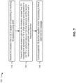
- Fig. 7 is a diagram illustrating an example process 700 performed, for example, by a base station, in accordance with various aspects of the present disclosure.
- Example process 700 is an example where the base station (e.g., base station 110 and/or the like) performs operations associated with repeating a TB using SDM.
- the base station e.g., base station 110 and/or the like
- process 700 may include receiving an indication that a UE is capable of transmitting or receiving TB repetitions using SDM (block 710).
- the base station e.g., using antenna 234, DEMOD 232, MIMO detector 236, receive processor 238, controller/processor 240, and/or the like
- process 700 may include transmitting, based at least in part on the indication, at least one DCI message that schedules a TB in a first resource and a repetition of the TB in a second resource, the first resource and the second resource at least partially overlapping in a time domain and a frequency domain (block 720).
- the base station may transmit, based at least in part on the indication, at least one DCI message that schedules a TB in a first resource and a repetition of the TB in a second resource, the first resource and the second resource at least partially overlapping in a time domain and a frequency domain, as described above.
- process 700 may include communicating the TB and the repetition of the TB according to the at least one DCI message (block 730).
- the base station e.g., using controller/processor 240, transmit processor 220, TX MIMO processor 230, MOD 232, antenna 234, DEMOD 232, MIMO detector 236, receive processor 238, and/or the like
- Process 700 may include additional aspects, such as any single aspect or any combination of aspects described below and/or in connection with one or more other processes described elsewhere herein.
- the indication indicates that the UE is capable of transmitting or receiving TB repetitions in a plurality of codewords scheduled by a single DCI message.
- the at least one DCI message is a single DCI message that schedules a transmission of a first codeword and a second codeword.
- the second codeword is a repetition of the first codeword.
- the first codeword is to be used for the TB and the second codeword is to be used for the repetition of the TB.
- a TB size associated with the transmission is based at least in part on the first codeword.
- process 700 includes transmitting a configuration that enables TB repetitions using SDM scheduled by a single DCI message.
- the at least one DCI message indicates that TB repetitions using SDM are scheduled by the at least one DCI message.
- an RNTI associated with the at least one DCI message indicates that TB repetitions using SDM are scheduled by the at least one DCI message.
- the indication indicates that the UE is capable of transmitting or receiving TB repetitions scheduled by a plurality of DCI messages.
- the at least one DCI message includes a first DCI message and a second DCI message, and the first DCI message is associated with a first CORESET associated with a first CORESET pool index, and the second DCI message is associated with a second CORESET associated with a second CORESET pool index.
- the at least one DCI message includes a first DCI message and a second DCI message, and the first DCI message schedules a transmission of a first codeword and the second DCI message schedules a transmission of a second codeword.
- the second codeword is a repetition of the first codeword.
- the at least one DCI message includes a first DCI message and a second DCI message, and the first DCI message and the second DCI message identify a same HARQ process identifier, a same TB size, a same NDI value, and different beam indications.
- process 700 includes transmitting a configuration that enables TB repetitions using SDM scheduled by a plurality of DCI messages.
- process 700 may include additional blocks, fewer blocks, different blocks, or differently arranged blocks than those depicted in Fig. 7 . Additionally, or alternatively, two or more of the blocks of process 700 may be performed in parallel.
- Fig. 8 is a conceptual data flow diagram 800 illustrating the data flow between different components in an example apparatus 802.
- the apparatus 802 may be a UE (e.g., UE 120).
- the apparatus 802 includes a transmission component 804 and/or a reception component 806.
- transmission component 804 may transmit an indication that the apparatus 802 is capable of transmitting or receiving TB repetitions using SDM. For example, transmission component 804 may transmit the indication to an apparatus 850 (e.g., base station 110).
- apparatus 850 e.g., base station 110
- reception component 806 may receive at least one DCI message that schedules a TB in a first resource and a repetition of the TB in a second resource. For example, reception component 806 may receive the at least one DCI from the apparatus 850. The first resource and the second resource may at least partially overlap in a time domain and a frequency domain. Reception component 806 may receive the at least one DCI message based at least in part on transmission component 804 transmitting the indication.
- transmission component 804 and/or reception component 806 may communicate the TB and the repetition of the TB according to the at least one DCI message. For example, transmission component 804 and/or reception component 806 may communicate with the apparatus 850. In some aspects, transmission component 804 may transmit the TB and the repetition of the TB. In some aspects, reception component 806 may receive the TB and the repetition of the TB.
- the apparatus 802 may include additional components that perform each of the blocks of the algorithm in the aforementioned process 600 of Fig. 6 , and/or the like. Each block in the aforementioned process 600 of Fig. 6 , and/or the like may be performed by a component and the apparatus 802 may include one or more of those components.
- the components may be one or more hardware components specifically configured to carry out the stated processes/algorithm, implemented by a processor configured to perform the stated processes/algorithm, stored within a computer-readable medium for implementation by a processor, or some combination thereof.
- Fig. 8 The number and arrangement of components shown in Fig. 8 are provided as an example. In practice, there may be additional components, fewer components, different components, or differently arranged components than those shown in Fig. 8 . Furthermore, two or more components shown in Fig. 8 may be implemented within a single component, or a single component shown in Fig. 8 may be implemented as multiple, distributed components. Additionally, or alternatively, a set of components (e.g., one or more components) shown in Fig. 8 may perform one or more functions described as being performed by another set of components shown in Fig. 8 .
- Fig. 9 is a conceptual data flow diagram 900 illustrating the data flow between different components in an example apparatus 902.
- the apparatus 902 may be a base station (e.g., base station 110).
- the apparatus 902 includes a reception component 904 and/or a transmission component 906.
- reception component 904 may receive an indication that an apparatus 950 (e.g., UE 120) is capable of transmitting or receiving TB repetitions using SDM. For example, reception component 904 may receive the indication from the apparatus 950.
- an apparatus 950 e.g., UE 120
- reception component 904 may receive the indication from the apparatus 950.
- transmission component 906 may transmit at least one DCI message that schedules a TB in a first resource and a repetition of the TB in a second resource. For example, transmission component 906 may transmit the at least one DCI to the apparatus 950. The first resource and the second resource may at least partially overlap in a time domain and a frequency domain. Transmission component 906 may transmit the at least one DCI message based at least in part on reception component 904 receiving the indication.
- reception component 904 and/or transmission component 906 may communicate the TB and the repetition of the TB according to the at least one DCI message. For example, reception component 904 and/or transmission component 906 may communicate with the apparatus 950. In some aspects, reception component 904 may receive the TB and the repetition of the TB. In some aspects, transmission component 906 may transmit the TB and the repetition of the TB.
- the apparatus 902 may include additional components that perform each of the blocks of the algorithm in the aforementioned process 700 of Fig. 7 , and/or the like. Each block in the aforementioned process 700 of Fig. 7 , and/or the like may be performed by a component and the apparatus 902 may include one or more of those components.
- the components may be one or more hardware components specifically configured to carry out the stated processes/algorithm, implemented by a processor configured to perform the stated processes/algorithm, stored within a computer-readable medium for implementation by a processor, or some combination thereof.
- Fig. 9 The number and arrangement of components shown in Fig. 9 are provided as an example. In practice, there may be additional components, fewer components, different components, or differently arranged components than those shown in Fig. 9 . Furthermore, two or more components shown in Fig. 9 may be implemented within a single component, or a single component shown in Fig. 9 may be implemented as multiple, distributed components. Additionally, or alternatively, a set of components (e.g., one or more components) shown in Fig. 9 may perform one or more functions described as being performed by another set of components shown in Fig. 9 .
- ком ⁇ онент is intended to be broadly construed as hardware, firmware, and/or a combination of hardware and software.
- a processor is implemented in hardware, firmware, and/or a combination of hardware and software.
- satisfying a threshold may, depending on the context, refer to a value being greater than the threshold, greater than or equal to the threshold, less than the threshold, less than or equal to the threshold, equal to the threshold, not equal to the threshold, and/or the like.
- "at least one of: a, b, or c” is intended to cover a, b, c, a-b, a-c, b-c, and a-b-c, as well as any combination with multiples of the same element (e.g., a-a, a-a-a, a-a-b, a-a-c, a-b-b, a-c-c, b-b, b-b-b, b-b-c, c-c, and c-c-c or any other ordering of a, b, and c).
Landscapes
- Engineering & Computer Science (AREA)
- Signal Processing (AREA)
- Computer Networks & Wireless Communication (AREA)
- Mobile Radio Communication Systems (AREA)
Claims (15)
- Ein Verfahren zur drahtlosen Kommunikation, das von einem Benutzergerät, UE (120), durchgeführt wird, aufweisend:Übertragen (610) einer Anzeige an eine Basisstation (110), dass das UE (120) in der Lage ist, Transportblock-, TB-, Wiederholungen unter Verwendung von räumlichem Teilungsmultiplexen, SDM, zu übertragen oder zu empfangen;Empfangen (620) zumindest einer Abwärtsverbindungs-Steuerungsinformationsnachricht, DCI-Nachricht, von der Basisstation (110), die zumindest teilweise auf der Anzeige basiert, die einen TB in einer ersten Ressource und eine Wiederholung des TB in einer zweiten Ressource plant, wobei sich die erste Ressource und die zweite Ressource zumindest teilweise in einem Zeitbereich und einem Frequenzbereich überlappen; undKommunizieren (630) des TB und der Wiederholung des TB unter Verwendung unterschiedlicher Antennenfelder gemäß der zumindest einen DCI-Nachricht.
- Das Verfahren nach Anspruch 1, wobei die Anzeige anzeigt, dass die UE (120) in der Lage ist, TB-Wiederholungen in einer Vielzahl von Codewörtern zu übertragen oder zu empfangen, die durch eine einzelne DCI-Nachricht geplant werden.
- Das Verfahren nach Anspruch 1, wobei die zumindest eine DCI-Nachricht eine einzelne DCI-Nachricht ist, die eine Übertragung eines ersten Codeworts und eines zweiten Codeworts plant, wobei vorzugsweise das zweite Codewort eine Wiederholung des ersten Codeworts ist oder wobei das erste Codewort für die TB verwendet werden soll und das zweite Codewort für die Wiederholung der TB verwendet werden soll, bevorzugter, wobei eine mit der Übertragung verbundene TB-Größe zumindest teilweise auf dem ersten Codewort basiert.
- Das Verfahren nach Anspruch 1, wobei die zumindest eine DCI-Nachricht anzeigt, dass TB-Wiederholungen unter Verwendung von SDM durch die zumindest eine DCI-Nachricht geplant werden.
- Das Verfahren nach Anspruch 1, wobei ein temporärer Funknetz-Identifizierer, der mit der zumindest einen DCI-Nachricht verknüpft ist, anzeigt, dass TB-Wiederholungen unter Verwendung von SDM durch die zumindest eine DCI-Nachricht geplant werden.
- Das Verfahren nach Anspruch 1, wobei die Anzeige anzeigt, dass die UE (120) in der Lage ist, TB-Wiederholungen zu übertragen oder zu empfangen, die durch eine Vielzahl von DCI-Nachrichten geplant werden.
- Das Verfahren nach Anspruch 1, wobei die zumindest eine DCI-Nachricht eine erste DCI-Nachricht und eine zweite DCI-Nachricht umfasst, und
wobei die erste DCI-Nachricht mit einem ersten Steuerressourcen-Satz CORESET verknüpft ist, der mit einem ersten CORESET-Poolindex verknüpft ist, und die zweite DCI-Nachricht mit einem zweiten CORESET verknüpft ist, der mit einem zweiten CORESET-Poolindex verknüpft ist. - Das Verfahren nach Anspruch 1, wobei die zumindest eine DCI-Nachricht eine erste DCI-Nachricht und eine zweite DCI-Nachricht umfasst und wobei die erste DCI-Nachricht eine Übertragung eines ersten Codeworts plant und die zweite DCI-Nachricht eine Übertragung eines zweiten Codeworts plant, wobei das zweite Codewort vorzugsweise eine Wiederholung des ersten Codeworts ist.
- Das Verfahren nach Anspruch 1, wobei die zumindest eine DCI-Nachricht eine erste DCI-Nachricht und eine zweite DCI-Nachricht umfasst, und
wobei die erste DCI-Nachricht und die zweite DCI-Nachricht einen gleichen hybriden automatischen Wiederholungsanforderungs-Prozessidentifizierer, eine gleiche TB-Größe, einen gleichen neuen Datenindikatorwert und unterschiedliche Strahlindikationen identifizieren. - Ein Verfahren zur drahtlosen Kommunikation, das von einer Basisstation (110) durchgeführt wird, aufweisend:Empfangen (710), von einem Benutzergerät, UE (120), einer Anzeige, dass das UE (120) in der Lage ist, Transportblock-, TB-, Wiederholungen unter Verwendung von räumlichem Multiplexen, SDM, zu übertragen oder zu empfangen;Übertragen (720) zumindest einer Abwärtsverbindungs-Steuerungsinformationsnachricht, DCI-Nachricht, an das UE (120), die zumindest teilweise auf der Anzeige basiert, die einen TB in einer ersten Ressource und eine Wiederholung des TB in einer zweiten Ressource plant, wobei sich die erste Ressource und die zweite Ressource zumindest teilweise in einem Zeitbereich und einem Frequenzbereich überlappen; undÜbertragen (730) des TB und der Wiederholung des TB gemäß der zumindest einen DCI-Nachricht.
- Das Verfahren nach Anspruch 10, weiter aufweisend:
Übertragen einer Konfiguration, die TB-Wiederholungen unter Verwendung von SDM ermöglicht, die durch eine einzelne DCI-Nachricht geplant werden. - Das Verfahren nach Anspruch 10, weiter aufweisend:
Übertragen einer Konfiguration, die TB-Wiederholungen unter Verwendung von SDM ermöglicht, die durch eine Vielzahl von DCI-Nachrichten geplant werden. - Ein computerlesbares Medium, das eine oder mehrere Anweisungen für die drahtlose Kommunikation speichert, wobei die eine oder mehreren Anweisungen, wenn sie von einem Benutzergerät ausgeführt werden, das Benutzergerät (UE) veranlassen, ein Verfahren gemäß einem der Ansprüche 1 bis 9 auszuführen, oder wenn sie von einer Basisstation ausgeführt werden, die Basisstation (110) veranlassen, ein Verfahren gemäß einem der Ansprüche 10 bis 12 auszuführen.
- Eine Vorrichtung zur drahtlosen Kommunikation, die Folgendes aufweist:Mittel zum Übertragen einer Anzeige an eine Basisstation (110), dass die Vorrichtung zur Übertragung oder zum Empfang von Transportblock-Wiederholungen, TB, unter Verwendung von räumlichem Multiplexen, SDM, fähig ist;Mittel zum Empfangen von zumindest einer Abwärtsverbindungs-Steuerungsinformationsnachricht, DCI-Nachricht, die zumindest teilweise auf der Anzeige basiert, von der Basisstation (110), die einen TB in einer ersten Ressource und eine Wiederholung des TB in einer zweiten Ressource plant, wobei die erste Ressource und die zweite Ressource sich zumindest teilweise in einem Zeitbereich und einem Frequenzbereich überlappen; undMittel zum Kommunizieren des TB und der Wiederholung des TB unter Verwendung unterschiedlicher Antennenfelder gemäß der zumindest einen DCI-Nachricht.
- Eine Vorrichtung zur drahtlosen Kommunikation, aufweisend:Mittel zum Empfangen einer Anzeige von einem Benutzergerät UE (120), dass das UE (120) in der Lage ist, Transportblock-Wiederholungen TB unter Verwendung von räumlichem Teilungsmultiplexing SDM zu übertragen oder zu empfangen;Mittel zum Übertragen zumindest einer Abwärtsverbindungs-Steuerungsinformationsnachricht, DCI-Nachricht, an die UE (120), die zumindest teilweise auf der Anzeige basiert, die einen TB in einer ersten Ressource und eine Wiederholung des TB in einer zweiten Ressource plant, wobei sich die erste Ressource und die zweite Ressource zumindest teilweise in einem Zeitbereich und einem Frequenzbereich überlappen; undMittel zum Kommunizieren des TB und der Wiederholung des TB gemäß der zumindest einen DCI-Nachricht.
Applications Claiming Priority (1)
| Application Number | Priority Date | Filing Date | Title |
|---|---|---|---|
| PCT/CN2020/085764 WO2021212295A1 (en) | 2020-04-21 | 2020-04-21 | Techniques for repeating a transport block using spatial division multiplexing |
Publications (3)
| Publication Number | Publication Date |
|---|---|
| EP4140212A1 EP4140212A1 (de) | 2023-03-01 |
| EP4140212A4 EP4140212A4 (de) | 2023-12-06 |
| EP4140212B1 true EP4140212B1 (de) | 2024-10-16 |
Family
ID=78270980
Family Applications (1)
| Application Number | Title | Priority Date | Filing Date |
|---|---|---|---|
| EP20931762.7A Active EP4140212B1 (de) | 2020-04-21 | 2020-04-21 | Techniken zur wiederholung eines transportblocks unter verwendung von räumlichem multiplexen |
Country Status (3)
| Country | Link |
|---|---|
| US (1) | US12395228B2 (de) |
| EP (1) | EP4140212B1 (de) |
| WO (1) | WO2021212295A1 (de) |
Families Citing this family (7)
| Publication number | Priority date | Publication date | Assignee | Title |
|---|---|---|---|---|
| CN120499688A (zh) * | 2020-06-30 | 2025-08-15 | 松下电器(美国)知识产权公司 | 终端、通信方法以及集成电路 |
| JP2024527664A (ja) * | 2021-07-23 | 2024-07-26 | インテル コーポレイション | 強化されたマルチレイヤアップリンク伝送 |
| CN116419408A (zh) * | 2021-12-28 | 2023-07-11 | 维沃移动通信有限公司 | 参考信号端口指示方法、终端及网络侧设备 |
| KR20230109998A (ko) * | 2022-01-14 | 2023-07-21 | 삼성전자주식회사 | 통신 시스템에서 제어 정보 및 데이터를 송수신하기 위한 장치 및 방법 |
| CN119156868A (zh) * | 2022-02-10 | 2024-12-17 | 株式会社Ntt都科摩 | 终端、无线通信方法以及基站 |
| US20240276461A1 (en) * | 2023-02-10 | 2024-08-15 | Qualcomm Incorporated | Tbs adjustment and adaptation for multiple and repeated transmissions in full duplex networks |
| WO2026011584A1 (en) * | 2024-07-08 | 2026-01-15 | Huawei Technologies Co., Ltd. | Method, apparatus and system of dci scheduling for progressive rateless coding |
Family Cites Families (7)
| Publication number | Priority date | Publication date | Assignee | Title |
|---|---|---|---|---|
| EP4054101A3 (de) * | 2016-11-04 | 2023-01-04 | Motorola Mobility LLC | Identifizierung einer ressource zur übertragung eines ersten uplink-kanals |
| EP4459937A3 (de) | 2017-06-13 | 2025-01-22 | Apple Inc. | Verbesserung bei planung und harq-ack-rückkopplung für urllc, multiplexing-schema für steuer/datenkanal und dm-rs |
| US10568128B2 (en) | 2017-06-14 | 2020-02-18 | Qualcomm Incorporated | Techniques and apparatuses for scheduling request acknowledgement |
| US10560901B2 (en) | 2018-02-16 | 2020-02-11 | Lenovo (Singapore) Pte. Ltd. | Method and apparatus having power control for grant-free uplink transmission |
| CN112567662B (zh) * | 2018-08-10 | 2024-07-05 | 苹果公司 | 用于新空口(nr)的数据和控制传输增强 |
| US11050525B2 (en) | 2018-09-27 | 2021-06-29 | Huawei Technologies Co., Ltd. | System and method for control and data channel reliability enhancement using multiple diversity domains |
| WO2020204540A1 (ko) * | 2019-03-29 | 2020-10-08 | 엘지전자 주식회사 | 무선 통신 시스템에서 데이터 송수신 방법 및 이에 대한 장치 |
-
2020
- 2020-04-21 EP EP20931762.7A patent/EP4140212B1/de active Active
- 2020-04-21 WO PCT/CN2020/085764 patent/WO2021212295A1/en not_active Ceased
- 2020-04-21 US US17/996,567 patent/US12395228B2/en active Active
Also Published As
| Publication number | Publication date |
|---|---|
| CN115336345A (zh) | 2022-11-11 |
| US20230208568A1 (en) | 2023-06-29 |
| EP4140212A4 (de) | 2023-12-06 |
| EP4140212A1 (de) | 2023-03-01 |
| WO2021212295A1 (en) | 2021-10-28 |
| US12395228B2 (en) | 2025-08-19 |
Similar Documents
| Publication | Publication Date | Title |
|---|---|---|
| EP3987702B1 (de) | Frequenzbereichsressourcenzuteilung für frequenzmultiplexschemata mit einzel-downlink-steuerinformationen in verbindung mit mehreren übertragungskonfigurationsanzeigezuständen | |
| EP4637246A2 (de) | Planung von broadcast- oder multicast-kommunikationen für new radio | |
| US11382068B2 (en) | Semi-persistent scheduling for broadcast or multicast | |
| US11963163B2 (en) | LCP restriction based on a CORESET pool index value | |
| US12088362B2 (en) | Precoder indication for non-codebook-based uplink transmissions | |
| EP4140212B1 (de) | Techniken zur wiederholung eines transportblocks unter verwendung von räumlichem multiplexen | |
| US11800529B2 (en) | Overlapping semi-persistent scheduling for multiple transmit receive points | |
| EP3900248B1 (de) | Verwendung einer präemptionsanzeige im zusammenhang mit einer quasi-colocation-beziehung | |
| WO2021184296A1 (en) | Configuration and indication for enabling uplink transmission with multiple codewords | |
| US11374696B2 (en) | Hybrid automatic repeat request (HARQ) process partitioning | |
| US11470588B2 (en) | Techniques for managing physical uplink control channel grouping for multiple transmit receive points | |
| CN115280705A (zh) | 上行链路传输配置指示状态信令 | |
| EP3991340A1 (de) | Dynamische umschaltung von suchraumkonfigurationen unter benutzergerätekapazität | |
| US12587258B2 (en) | Beam failure recovery medium access control signaling for multi transmit-receive point system | |
| EP4097892B1 (de) | Dynamisches wechseln von übertragungskonfigurationsanzeigezuständen unter verwendung eines einzigen steuerressourcensatzes | |
| US12500641B2 (en) | Subband reporting for channel state information of multiple transmission reception points | |
| CN115336345B (zh) | 用于使用空分复用重复传输块的技术 |
Legal Events
| Date | Code | Title | Description |
|---|---|---|---|
| STAA | Information on the status of an ep patent application or granted ep patent |
Free format text: STATUS: THE INTERNATIONAL PUBLICATION HAS BEEN MADE |
|
| PUAI | Public reference made under article 153(3) epc to a published international application that has entered the european phase |
Free format text: ORIGINAL CODE: 0009012 |
|
| STAA | Information on the status of an ep patent application or granted ep patent |
Free format text: STATUS: REQUEST FOR EXAMINATION WAS MADE |
|
| 17P | Request for examination filed |
Effective date: 20220824 |
|
| AK | Designated contracting states |
Kind code of ref document: A1 Designated state(s): AL AT BE BG CH CY CZ DE DK EE ES FI FR GB GR HR HU IE IS IT LI LT LU LV MC MK MT NL NO PL PT RO RS SE SI SK SM TR |
|
| DAV | Request for validation of the european patent (deleted) | ||
| DAX | Request for extension of the european patent (deleted) | ||
| A4 | Supplementary search report drawn up and despatched |
Effective date: 20231106 |
|
| RIC1 | Information provided on ipc code assigned before grant |
Ipc: H04B 7/06 20060101ALI20231030BHEP Ipc: H04L 5/00 20060101ALI20231030BHEP Ipc: H04L 1/08 20060101ALI20231030BHEP Ipc: H04L 1/1829 20230101ALI20231030BHEP Ipc: H04L 1/1867 20230101ALI20231030BHEP Ipc: H04W 72/04 20230101AFI20231030BHEP |
|
| GRAP | Despatch of communication of intention to grant a patent |
Free format text: ORIGINAL CODE: EPIDOSNIGR1 |
|
| STAA | Information on the status of an ep patent application or granted ep patent |
Free format text: STATUS: GRANT OF PATENT IS INTENDED |
|
| INTG | Intention to grant announced |
Effective date: 20240604 |
|
| GRAS | Grant fee paid |
Free format text: ORIGINAL CODE: EPIDOSNIGR3 |
|
| GRAA | (expected) grant |
Free format text: ORIGINAL CODE: 0009210 |
|
| STAA | Information on the status of an ep patent application or granted ep patent |
Free format text: STATUS: THE PATENT HAS BEEN GRANTED |
|
| AK | Designated contracting states |
Kind code of ref document: B1 Designated state(s): AL AT BE BG CH CY CZ DE DK EE ES FI FR GB GR HR HU IE IS IT LI LT LU LV MC MK MT NL NO PL PT RO RS SE SI SK SM TR |
|
| REG | Reference to a national code |
Ref country code: GB Ref legal event code: FG4D |
|
| REG | Reference to a national code |
Ref country code: CH Ref legal event code: EP Ref country code: DE Ref legal event code: R096 Ref document number: 602020039744 Country of ref document: DE |
|
| REG | Reference to a national code |
Ref country code: IE Ref legal event code: FG4D |
|
| REG | Reference to a national code |
Ref country code: LT Ref legal event code: MG9D |
|
| REG | Reference to a national code |
Ref country code: NL Ref legal event code: MP Effective date: 20241016 |
|
| REG | Reference to a national code |
Ref country code: AT Ref legal event code: MK05 Ref document number: 1733941 Country of ref document: AT Kind code of ref document: T Effective date: 20241016 |
|
| PG25 | Lapsed in a contracting state [announced via postgrant information from national office to epo] |
Ref country code: NL Free format text: LAPSE BECAUSE OF FAILURE TO SUBMIT A TRANSLATION OF THE DESCRIPTION OR TO PAY THE FEE WITHIN THE PRESCRIBED TIME-LIMIT Effective date: 20241016 |
|
| PG25 | Lapsed in a contracting state [announced via postgrant information from national office to epo] |
Ref country code: NL Free format text: LAPSE BECAUSE OF FAILURE TO SUBMIT A TRANSLATION OF THE DESCRIPTION OR TO PAY THE FEE WITHIN THE PRESCRIBED TIME-LIMIT Effective date: 20241016 |
|
| PG25 | Lapsed in a contracting state [announced via postgrant information from national office to epo] |
Ref country code: HR Free format text: LAPSE BECAUSE OF FAILURE TO SUBMIT A TRANSLATION OF THE DESCRIPTION OR TO PAY THE FEE WITHIN THE PRESCRIBED TIME-LIMIT Effective date: 20241016 Ref country code: IS Free format text: LAPSE BECAUSE OF FAILURE TO SUBMIT A TRANSLATION OF THE DESCRIPTION OR TO PAY THE FEE WITHIN THE PRESCRIBED TIME-LIMIT Effective date: 20250216 Ref country code: PT Free format text: LAPSE BECAUSE OF FAILURE TO SUBMIT A TRANSLATION OF THE DESCRIPTION OR TO PAY THE FEE WITHIN THE PRESCRIBED TIME-LIMIT Effective date: 20250217 |
|
| PG25 | Lapsed in a contracting state [announced via postgrant information from national office to epo] |
Ref country code: FI Free format text: LAPSE BECAUSE OF FAILURE TO SUBMIT A TRANSLATION OF THE DESCRIPTION OR TO PAY THE FEE WITHIN THE PRESCRIBED TIME-LIMIT Effective date: 20241016 |
|
| PG25 | Lapsed in a contracting state [announced via postgrant information from national office to epo] |
Ref country code: BG Free format text: LAPSE BECAUSE OF FAILURE TO SUBMIT A TRANSLATION OF THE DESCRIPTION OR TO PAY THE FEE WITHIN THE PRESCRIBED TIME-LIMIT Effective date: 20241016 |
|
| PG25 | Lapsed in a contracting state [announced via postgrant information from national office to epo] |
Ref country code: ES Free format text: LAPSE BECAUSE OF FAILURE TO SUBMIT A TRANSLATION OF THE DESCRIPTION OR TO PAY THE FEE WITHIN THE PRESCRIBED TIME-LIMIT Effective date: 20241016 |
|
| PG25 | Lapsed in a contracting state [announced via postgrant information from national office to epo] |
Ref country code: NO Free format text: LAPSE BECAUSE OF FAILURE TO SUBMIT A TRANSLATION OF THE DESCRIPTION OR TO PAY THE FEE WITHIN THE PRESCRIBED TIME-LIMIT Effective date: 20250116 |
|
| PG25 | Lapsed in a contracting state [announced via postgrant information from national office to epo] |
Ref country code: LV Free format text: LAPSE BECAUSE OF FAILURE TO SUBMIT A TRANSLATION OF THE DESCRIPTION OR TO PAY THE FEE WITHIN THE PRESCRIBED TIME-LIMIT Effective date: 20241016 Ref country code: GR Free format text: LAPSE BECAUSE OF FAILURE TO SUBMIT A TRANSLATION OF THE DESCRIPTION OR TO PAY THE FEE WITHIN THE PRESCRIBED TIME-LIMIT Effective date: 20250117 Ref country code: AT Free format text: LAPSE BECAUSE OF FAILURE TO SUBMIT A TRANSLATION OF THE DESCRIPTION OR TO PAY THE FEE WITHIN THE PRESCRIBED TIME-LIMIT Effective date: 20241016 |
|
| PG25 | Lapsed in a contracting state [announced via postgrant information from national office to epo] |
Ref country code: PL Free format text: LAPSE BECAUSE OF FAILURE TO SUBMIT A TRANSLATION OF THE DESCRIPTION OR TO PAY THE FEE WITHIN THE PRESCRIBED TIME-LIMIT Effective date: 20241016 |
|
| PG25 | Lapsed in a contracting state [announced via postgrant information from national office to epo] |
Ref country code: RS Free format text: LAPSE BECAUSE OF FAILURE TO SUBMIT A TRANSLATION OF THE DESCRIPTION OR TO PAY THE FEE WITHIN THE PRESCRIBED TIME-LIMIT Effective date: 20250116 |
|
| PG25 | Lapsed in a contracting state [announced via postgrant information from national office to epo] |
Ref country code: SM Free format text: LAPSE BECAUSE OF FAILURE TO SUBMIT A TRANSLATION OF THE DESCRIPTION OR TO PAY THE FEE WITHIN THE PRESCRIBED TIME-LIMIT Effective date: 20241016 |
|
| PG25 | Lapsed in a contracting state [announced via postgrant information from national office to epo] |
Ref country code: DK Free format text: LAPSE BECAUSE OF FAILURE TO SUBMIT A TRANSLATION OF THE DESCRIPTION OR TO PAY THE FEE WITHIN THE PRESCRIBED TIME-LIMIT Effective date: 20241016 |
|
| REG | Reference to a national code |
Ref country code: DE Ref legal event code: R097 Ref document number: 602020039744 Country of ref document: DE |
|
| PG25 | Lapsed in a contracting state [announced via postgrant information from national office to epo] |
Ref country code: EE Free format text: LAPSE BECAUSE OF FAILURE TO SUBMIT A TRANSLATION OF THE DESCRIPTION OR TO PAY THE FEE WITHIN THE PRESCRIBED TIME-LIMIT Effective date: 20241016 |
|
| PG25 | Lapsed in a contracting state [announced via postgrant information from national office to epo] |
Ref country code: RO Free format text: LAPSE BECAUSE OF FAILURE TO SUBMIT A TRANSLATION OF THE DESCRIPTION OR TO PAY THE FEE WITHIN THE PRESCRIBED TIME-LIMIT Effective date: 20241016 |
|
| PG25 | Lapsed in a contracting state [announced via postgrant information from national office to epo] |
Ref country code: SK Free format text: LAPSE BECAUSE OF FAILURE TO SUBMIT A TRANSLATION OF THE DESCRIPTION OR TO PAY THE FEE WITHIN THE PRESCRIBED TIME-LIMIT Effective date: 20241016 |
|
| PG25 | Lapsed in a contracting state [announced via postgrant information from national office to epo] |
Ref country code: CZ Free format text: LAPSE BECAUSE OF FAILURE TO SUBMIT A TRANSLATION OF THE DESCRIPTION OR TO PAY THE FEE WITHIN THE PRESCRIBED TIME-LIMIT Effective date: 20241016 |
|
| PG25 | Lapsed in a contracting state [announced via postgrant information from national office to epo] |
Ref country code: IT Free format text: LAPSE BECAUSE OF FAILURE TO SUBMIT A TRANSLATION OF THE DESCRIPTION OR TO PAY THE FEE WITHIN THE PRESCRIBED TIME-LIMIT Effective date: 20241016 |
|
| PLBE | No opposition filed within time limit |
Free format text: ORIGINAL CODE: 0009261 |
|
| STAA | Information on the status of an ep patent application or granted ep patent |
Free format text: STATUS: NO OPPOSITION FILED WITHIN TIME LIMIT |
|
| PG25 | Lapsed in a contracting state [announced via postgrant information from national office to epo] |
Ref country code: SE Free format text: LAPSE BECAUSE OF FAILURE TO SUBMIT A TRANSLATION OF THE DESCRIPTION OR TO PAY THE FEE WITHIN THE PRESCRIBED TIME-LIMIT Effective date: 20241016 |
|
| 26N | No opposition filed |
Effective date: 20250717 |
|
| REG | Reference to a national code |
Ref country code: DE Ref legal event code: R119 Ref document number: 602020039744 Country of ref document: DE |
|
| REG | Reference to a national code |
Ref country code: CH Ref legal event code: H13 Free format text: ST27 STATUS EVENT CODE: U-0-0-H10-H13 (AS PROVIDED BY THE NATIONAL OFFICE) Effective date: 20251125 |
|
| PG25 | Lapsed in a contracting state [announced via postgrant information from national office to epo] |
Ref country code: LU Free format text: LAPSE BECAUSE OF NON-PAYMENT OF DUE FEES Effective date: 20250421 |
|
| PG25 | Lapsed in a contracting state [announced via postgrant information from national office to epo] |
Ref country code: MC Free format text: LAPSE BECAUSE OF FAILURE TO SUBMIT A TRANSLATION OF THE DESCRIPTION OR TO PAY THE FEE WITHIN THE PRESCRIBED TIME-LIMIT Effective date: 20241016 |
|
| GBPC | Gb: european patent ceased through non-payment of renewal fee |
Effective date: 20250421 |
|
| REG | Reference to a national code |
Ref country code: BE Ref legal event code: MM Effective date: 20250430 |
|
| PG25 | Lapsed in a contracting state [announced via postgrant information from national office to epo] |
Ref country code: DE Free format text: LAPSE BECAUSE OF NON-PAYMENT OF DUE FEES Effective date: 20251104 |
|
| PG25 | Lapsed in a contracting state [announced via postgrant information from national office to epo] |
Ref country code: GB Free format text: LAPSE BECAUSE OF NON-PAYMENT OF DUE FEES Effective date: 20250421 |
|
| PG25 | Lapsed in a contracting state [announced via postgrant information from national office to epo] |
Ref country code: FR Free format text: LAPSE BECAUSE OF NON-PAYMENT OF DUE FEES Effective date: 20250430 |
|
| PG25 | Lapsed in a contracting state [announced via postgrant information from national office to epo] |
Ref country code: BE Free format text: LAPSE BECAUSE OF NON-PAYMENT OF DUE FEES Effective date: 20250430 |
|
| PG25 | Lapsed in a contracting state [announced via postgrant information from national office to epo] |
Ref country code: CH Free format text: LAPSE BECAUSE OF NON-PAYMENT OF DUE FEES Effective date: 20250430 |
|
| PG25 | Lapsed in a contracting state [announced via postgrant information from national office to epo] |
Ref country code: IE Free format text: LAPSE BECAUSE OF NON-PAYMENT OF DUE FEES Effective date: 20250421 |