EP4140357A1 - Récipient de maquillage et procédé d'utilisation de celui-ci - Google Patents
Récipient de maquillage et procédé d'utilisation de celui-ci Download PDFInfo
- Publication number
- EP4140357A1 EP4140357A1 EP21793610.3A EP21793610A EP4140357A1 EP 4140357 A1 EP4140357 A1 EP 4140357A1 EP 21793610 A EP21793610 A EP 21793610A EP 4140357 A1 EP4140357 A1 EP 4140357A1
- Authority
- EP
- European Patent Office
- Prior art keywords
- cup
- slideway
- pushing
- material cup
- stroke
- Prior art date
- Legal status (The legal status is an assumption and is not a legal conclusion. Google has not performed a legal analysis and makes no representation as to the accuracy of the status listed.)
- Pending
Links
- 238000000034 method Methods 0.000 title claims abstract description 25
- 239000000463 material Substances 0.000 claims abstract description 229
- 239000002537 cosmetic Substances 0.000 claims description 51
- 230000001174 ascending effect Effects 0.000 claims description 25
- 101150038956 cup-4 gene Proteins 0.000 description 76
- 230000002457 bidirectional effect Effects 0.000 description 3
- 238000004519 manufacturing process Methods 0.000 description 2
- 239000007779 soft material Substances 0.000 description 2
- 230000000694 effects Effects 0.000 description 1
- 239000003292 glue Substances 0.000 description 1
- 239000007934 lip balm Substances 0.000 description 1
- -1 lipstick Substances 0.000 description 1
- 238000000465 moulding Methods 0.000 description 1
- 238000004806 packaging method and process Methods 0.000 description 1
- 239000003973 paint Substances 0.000 description 1
- 239000007787 solid Substances 0.000 description 1
- 238000006467 substitution reaction Methods 0.000 description 1
- 239000002699 waste material Substances 0.000 description 1
Images





Classifications
-
- A—HUMAN NECESSITIES
- A45—HAND OR TRAVELLING ARTICLES
- A45D—HAIRDRESSING OR SHAVING EQUIPMENT; EQUIPMENT FOR COSMETICS OR COSMETIC TREATMENTS, e.g. FOR MANICURING OR PEDICURING
- A45D40/00—Casings or accessories specially adapted for storing or handling solid or pasty toiletry or cosmetic substances, e.g. shaving soaps or lipsticks
- A45D40/02—Casings wherein movement of the lipstick or like solid is a sliding movement
- A45D40/04—Casings wherein movement of the lipstick or like solid is a sliding movement effected by a screw
-
- A—HUMAN NECESSITIES
- A45—HAND OR TRAVELLING ARTICLES
- A45D—HAIRDRESSING OR SHAVING EQUIPMENT; EQUIPMENT FOR COSMETICS OR COSMETIC TREATMENTS, e.g. FOR MANICURING OR PEDICURING
- A45D40/00—Casings or accessories specially adapted for storing or handling solid or pasty toiletry or cosmetic substances, e.g. shaving soaps or lipsticks
-
- A—HUMAN NECESSITIES
- A45—HAND OR TRAVELLING ARTICLES
- A45D—HAIRDRESSING OR SHAVING EQUIPMENT; EQUIPMENT FOR COSMETICS OR COSMETIC TREATMENTS, e.g. FOR MANICURING OR PEDICURING
- A45D40/00—Casings or accessories specially adapted for storing or handling solid or pasty toiletry or cosmetic substances, e.g. shaving soaps or lipsticks
- A45D2040/0006—Accessories
-
- A—HUMAN NECESSITIES
- A45—HAND OR TRAVELLING ARTICLES
- A45D—HAIRDRESSING OR SHAVING EQUIPMENT; EQUIPMENT FOR COSMETICS OR COSMETIC TREATMENTS, e.g. FOR MANICURING OR PEDICURING
- A45D40/00—Casings or accessories specially adapted for storing or handling solid or pasty toiletry or cosmetic substances, e.g. shaving soaps or lipsticks
- A45D40/14—Casings with ejector for waste stick or the like
Definitions
- the present disclosure relates to the field of cosmetic packaging, in particular to a cosmetic container and a method for using the same.
- a material body is placed in a cup body, and when the cup body is ascended and descended, the material body is driven to move out and back.
- the material body If most of the material body sticks out of the cup body, leaving a small part placed in the cup body, the material body needs to be made of a harder material, which reduces a user experience. In addition, most of the material body sticking out of the cup body also easily causes the material body to be broken, which affects the user experience.
- the present disclosure provides a cosmetic container and a method for using the same, which can improve a utilization rate of a material body in the cosmetic container, and meanwhile improve a user experience and a service life of the material body.
- An aspect of the present disclosure provides a cosmetic container, including: a threaded sleeve, wherein an inner wall of the threaded sleeve is provided with a first guide groove and a second guide groove forming a double helix; a rotating member, rotatably sleeved in the threaded sleeve, wherein a side wall of the rotating member is provided with a hollowed-out slideway pattern, and the slideway pattern includes at least a first slideway and a second slideway both extending axially and connected with each other; a material cup, rotatably sleeved in the rotating member, wherein a side wall of the material cup protrudes outwardly to form at least one first lug, the first lug passes through the slideway pattern and is limited in the first guide groove, and the side wall of the material cup is provided with a third slideway extending axially; and a pushing cup, rotatably sleeved in the material cup, wherein
- the third slideway is successively overlapped with the first slideway and the second slideway, forming a first combined slideway for the pushing cup and the material cup to ascend and descend synchronously and a second combined slideway only for the pushing cup to ascend and descend.
- the first lug and the third slideway are arranged in a same axis;
- the first combined slideway includes: the third slideway and a part of the first slideway that are overlapped with each other for the pushing cup to ascend and descend, and another part of the first slideway for the material cup to ascend and descend;
- the second combined slideway includes the third slideway and the second slideway that are overlapped with each other.
- the first slideway is provided with a material cup upper locking position for preventing the material cup from ascending.
- the first slideway is provided with a material cup lower locking position for preventing the material cup from descending and a pushing cup lower locking position for preventing the pushing cup from descending.
- the rotating member in the cosmetic container, includes a cylinder part sleeved in the threaded sleeve and an actuating part extending out of the threaded sleeve, the slideway pattern is hollowed out on a side wall of the cylinder part; and an end surface of the cylinder part connected with the actuating part is provided with first convex ribs for preventing the material cup from descending.
- a lower end surface of the material cup is provided with second convex ribs for preventing the pushing cup from descending.
- an inner wall of the material cup is provided with ribs extending axially
- an outer wall of the pushing cup is provided with grooves extending axially
- the ribs are axially slidably limited in the grooves.
- Another aspect of the present disclosure provides a method for using a cosmetic container, based on the above-mentioned cosmetic containers, wherein the method includes a first stroke of driving the material cup and the pushing cup to ascend and descend synchronously and a second stroke of only driving the pushing cup to ascend and descend; the first stroke includes a first ascending stroke and a first descending stroke, the second stroke includes a second ascending stroke and a second descending stroke, the first ascending stroke and the second ascending stroke are performed sequentially, and the second descending stroke and the first descending stroke are performed sequentially.
- the first ascending stroke includes: rotating the rotating member in a positive direction to drive the material cup and the pushing cup to ascend synchronously along the first combined slideway;
- the second ascending stroke includes: rotating the rotating member in the positive direction to drive the pushing cup to ascend along the second combined slideway;
- the second descending stroke includes: rotating the rotating member in a negative direction to drive the pushing cup to descend along the second combined slideway;
- the first descending stroke includes: rotating the rotating member in the negative direction to drive the material cup and the pushing cup to descend synchronously along the first combined slideway.
- the present disclosure includes at least the following advantages.
- the cosmetic container has at least two strokes.
- the material cup and the pushing cup can be ascended and descended synchronously.
- the pushing cup can be ascended and descended relative to the material body, so that the material body placed in the material cup can be completely used up, which improves the utilization rate of the material body.
- most of the material body can be placed in the material cup to avoid breaking, and soft materials can be flexibly selected to improve the user experience.
- the rotating member provides a sliding space for the material cup and the pushing cup; by sharing the slideway pattern between the material cup and the pushing cup, an area of the slideway pattern can be reduced to ensure firmness of the rotating member. Furthermore, with the third slideway extending axially, on the one hand, the material cup and the pushing cup can move in a same direction, and on the other hand, the third slideway can be overlapped with the first slideway and the second slideway of the slideway pattern, respectively, forming the first combined slideway for the material cup and the pushing cup to ascend and descend synchronously and the second combined slideway only for the pushing cup to ascend and descend, which is easy to operate.
- a cosmetic container of the present disclosure is used for containing paste materials, such as lipstick, lip balm, etc.
- the cosmetic container can also be applied to other similar fields, such as for containing solid glue, paint and the like.
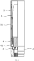
- FIG. 1 shows a cosmetic container in an embodiment
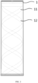
- FIG. 2 shows a structure of a threaded sleeve
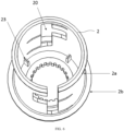
- FIG. 3 shows a structure of a rotating member
- FIG. 7 shows a structure of a material cup
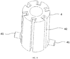
- FIG. 8 shows a structure of a pushing cup
- FIG. 9 shows an assembly structure of the material cup, the pushing cup and a material body.
- the cosmetic container in the embodiment includes the following components.
- FIG. 2 only schematically shows the first guide groove 11 and the second guide groove 12; in practical applications, the first guide groove 11 and the second guide groove 12 can be interchanged, as long as the double helix is formed.
- a rotating member 2 rotatably sleeved in the threaded sleeve 1, wherein a side wall of the rotating member 2 is provided with a hollowed-out slideway pattern 20.
- the slideway pattern 20 includes at least a first slideway 21 and a second slideway 22 both extending axially and connected with each other.
- the first slideway 21 and the second slideway 22 are respectively marked by two sections which extend axially and are filled with diagonal lines.
- the first lug 31 passes through the slideway pattern 20 and is limited in the first guide groove 11.
- the side wall of the material cup 3 is further provided with a third slideway 32 extending axially.
- a pair of first lugs 31 and a pair of third slideway 32 can be symmetrically arranged on the side wall of the material cup 3.
- a pushing cup 4 rotatably sleeved in the material cup 3, wherein a side wall of the pushing cup 4 protrudes outwardly to form at least one second lug 41.
- the second lug 41 passes successively through the third slideway 32 and the slideway pattern 20 and is limited in the second guide groove 12.
- FIG. 8 shows that the side wall of the pushing cup 4 is symmetrically provided with two second lugs 41, and each second lug 41 correspondingly passes through one of the third slideway 32.
- the cosmetic container of the embodiment has at least two strokes, including a first stroke during which the material cup 3 and the pushing cup 4 are ascended and descended synchronously and a second stroke during which only the pushing cup 4 is ascended and descended.
- a first stroke during which the material cup 3 and the pushing cup 4 are ascended and descended synchronously
- a second stroke during which only the pushing cup 4 is ascended and descended.
- the first guide groove 11 guides the first lugs 31 of the material cup 3 to ascend and descend along the slideway pattern 20
- the second guide groove 12 guides the second lugs 42 of the pushing cup 4 to ascend and descend along the slideway pattern 20.
- the material body 5 is ascended and descended along with the material cup 3 and the pushing cup 4, and the second part 52 of the material body 5 can be extended out of the rotating member 2 for use, and returned back to the rotating member 2 for storage.
- the material cup 3 is ascended to a certain level (for example, an upper end surface of the material cup 3 is ascended to be flush with or slightly higher than an upper end surface of the rotating part 2)
- the first stroke ends and the second stroke starts.
- the pushing cup 4 is ascended and descended relative to the material cup 3, and drives the first part 51 of the material body 5 placed in the material cup 3 to extend out of and return back to the material cup 3.
- the third slideway 32 extending axially keep the material cup 3 and the pushing cup 4 moving in a same direction during the first stroke, and make the pushing cup 4 move axially relative to the material cup 3 during the second stroke.
- the material body 5 Under a combined action of the material cup 3 and the pushing cup 4, firstly, the material body 5 can be completely extended out of the material cup 3, so that the material body 5 can be used up and a utilization rate can be improved; secondly, most of the material body 5 can be placed in the material cup 3, for example, the first part 51 can occupy for about 70% of an overall length of the material body 5, so as to avoid breaking and prolong a service life of the material body 5; thirdly, since most of the material body 5 is placed in the material cup 3, the material body 5 can be made of softer materials to improve a user experience. In addition, a height of the material cup 3 can be increased. A height of a traditional material cup accounts for about 30% of an overall height of a tube body, to avoid too much material being wasted in the material cup.
- the material body 5 can be completely extended out, so that the height of the material cup 3 can be greatly increased, for example accounting for 50%-90% of a height of the rotating member 2, thereby 50%-90% of the material body 5 can be placed in the material cup 3.
- the specific height of the material cup 3 can be flexibly determined as required.
- each third slideway 32 is successively overlapped with the first slideway 21 and the second slideway 22, forming a first combined slideway for the pushing cup 4 and the material cup 3 to ascend and descend synchronously and a second combined slideway only for the pushing cup 4 to ascend and descend.
- first lug 31 and the third slideway 32 on a same side are arranged in a same axis.
- the slideway pattern 20 hollowed out on the rotating member 2 is correspondingly increased.
- the first lug 31 and the third slideway 32 in the same axis (for example, the first lug 31 is arranged above the third slideway 32), on the one hand, it can facilitate an alignment during molding to improve accuracy, on the other hand, the first lugs 31 and the second lugs 41 can share part of the slideway pattern 20, thereby reducing an area of the slideway pattern 20 hollowed out on the rotating member 2, to improve firmness of the rotating member 2.
- the first lugs 31 and the second lugs 41 share the first slideway 21 of the slideway pattern 20.
- a dotted box C1 is used to indicate the first combined slideway
- a dotted box C2 is used to indicate the second combined slideway
- a shaded area filled with dots is used to indicate the third slideway.
- the first combined slideway C1 includes the third slideway and a part 21a of the first slideway (i.e., a shaded area filled with dots in the dotted box C1) overlapped with each other for the pushing cup 4 to ascend and descend, and another part 21b of the first slideway (i.e., a blank area in the dotted box C1) for the material cup 3 to ascend and descend.
- the second combined slideway C2 includes the third slideway and the second slideway 22 overlapped with each other for the pushing cup 4 to ascend and descend. During ascending and descending processes of the material cup 3, overlapping areas of the third slideway and the first slideway will be changed accordingly.
- the first slideway 21 can be provided with material cup upper locking positions to lock the material cup 3 when the material cup 3 is ascended to a certain level, thereby making the pushing cup 4 ascend and descend relative to the material cup 3.
- an upper end of the first slideway 21 is provided with the material cup upper locking positions 302 for locking the material cup 3. Under an action of the material cup upper locking positions 302, when the material cup 3 and the pushing cup 4 are synchronously ascended to the first lugs 31 of the material cup 3 reach the material cup upper locking positions 302, the material cup 3 is locked and can not continue to ascend.
- the pushing cup 4 reaches a connected area 4012 between the first slideway 21 and the second slideway 22. Subsequently, the material cup 3 is locked in the material cup upper locking positions 302, and the pushing cup 4 can be ascended and descended along the second slideway 22, relative to the material cup 3.
- the first slideway 21 is further provided with material cup lower locking positions 301 for preventing the material cup 3 from descending and pushing cup lower locking positions 401 for preventing the pushing cup 4 from descending, respectively.
- material cup lower locking positions 301 Under an action of the material cup lower locking positions 301, when the material cup 3 is descended to the first lugs 31 thereof reaching the material cup lower locking positions 301, the material cup 3 is locked and can not continue to descend.
- pushing cup lower locking positions 401 when the pushing cup 4 is descended to the second lugs 41 thereof reaching the pushing cup lower locking positions 401, the pushing cup 4 is locked and can not continue to descend.
- All of the material cup lower locking positions 301, the material cup upper locking positions 302 and the pushing cup lower locking positions 401 can be extended in a circumferential direction as shown in FIG. 5 . Due to locking effects of the material cup lower locking positions 301 and the pushing cup lower locking positions 401, when the cosmetic container is not in use (for example, in an idle state or a transportation state, etc.), the material cup lower locking positions 301 and the pushing cup lower locking positions 401 lock the material cup 3 and pushing cup 4 to prevent loosening, respectively.
- the material cup lower locking positions 301 and the pushing cup lower locking positions 401 will be unlocked, then the first lugs 31 of the material cup 3 and the second lugs 41 of the pushing cup 4 will be pushed, respectively by the first guide groove 11 and the second guide groove 12, into the first slideway 21 to enter a use state.
- the third slideway 32 extending axially keep the pushing cup 4 and the material cup 3 moving in the same direction, and further prevent the pushing cup 4 from slipping off to the material cup lower locking positions 301 when the pushing cup 4 is descended.
- a sliding trajectory of the first lug 31 of the material cup 3 is shown as a bidirectional dashed arrow 310, the first lug 31 slides along the first slideway 21 between the material cup lower locking position 301 and the material cup upper locking position 302.
- the material cup 3 can be descended until the first lugs 31 are locked in the material cup lower locking positions 301, and be ascended until the first lugs 31 are locked in the material cup upper locking positions 302.
- a sliding trajectory of the second lug 41 of the pushing cup 4 is shown as a bidirectional dashed arrow 410a, the second lug 41 slides along the first slideway 21 between the pushing cup lower locking position 401 and the connected area 4012.
- the second lugs 41 of the pushing cup 4 are locked in the pushing cup lower locking positions 401; and when the material cup 3 is ascended to the first lugs 31 locked in the material cup upper locking positions 302, the second lugs 41 of the pushing cup 4 reach the connected area 4012.
- the material cup 3 remains stationary since the first lugs 31 of the material cup 3 are locked in the material cup upper locking positions 302, and a sliding trajectory of the second lug 41 of the pushing cup 4 is shown as a bidirectional dashed arrow 410b, the second lug 41 slides along the second slideway 22 between a lower end (i.e., the connected area 4012) of the second slideway 22 and an upper end 402 of the second slideway 22.
- the rotating member 2 includes a cylinder part 2a sleeved in the threaded sleeve 1 and an actuating part 2b extending out of the threaded sleeve 1, and the slideway pattern 20 is hollowed out on a side wall of the cylinder part 2a.
- the actuating part 2b When using the cosmetic container, rotate the actuating part 2b, the rotating member 2 will be driven to rotate in the threaded sleeve 1, thereby the material cup 3 and/or the pushing cup 4 are driven to ascend and descend.
- An end surface of the cylinder part 2a connected to the actuating part 2b is provided with first convex ribs 23 for preventing the material cup 3 from descending; when the material cup 3 is descended to its lower end surface being pressed against the first convex ribs 23, its descending stops, so that the material cup 3 will not be descended unrestrictedly, thereby avoiding damage to the cosmetic container.
- a lower end surface of the material cup 3 may be provided with second convex ribs (not shown in the drawings) for preventing the pushing cup 4 from descending.
- second convex ribs not shown in the drawings
- an inner wall of the material cup 3 is provided with ribs 33 extending axially
- an outer wall of the pushing cup 4 is provided with grooves 42 extending axially
- the ribs 33 are axially slidably limited in the grooves 42.
- the embedded ribs 33 and grooves 42 ensure that the material cup 3 and the pushing cup 4 move in the same direction, and further play a limiting role on the pushing cup 4 to prevent the pushing cup 4 from slipping off.
- Embodiments of the present disclosure also provide a method for using the above-mentioned cosmetic containers, the method includes a first stroke of driving the material cup 3 and the pushing cup 4 to ascend and descend synchronously and a second stroke of only driving the pushing cup 4 to ascend and descend.
- the first stroke includes a first ascending stroke and a first descending stroke
- the second stroke includes a second ascending stroke and a second descending stroke
- the first ascending stroke and the second ascending stroke are performed sequentially
- the second descending stroke and the first descending stroke are performed sequentially.
- the first ascending stroke includes: rotating the rotating member in a positive direction, driving the pushing cup and the material cup to ascend synchronously along the first combined slideway; and the second ascending stroke includes: rotating the rotating member in the positive direction, driving the pushing cup to ascend along the second combined slideway.
- the second descending stroke includes: rotating the rotating member in a negative direction, driving the pushing cup to descend along the second combined slideway; and the first descending stroke includes: rotating the rotating member in the negative direction, driving the material cup and the pushing cup to descend synchronously along the first combined slideway.
- FIGS. 10a to 10d illustrate the first ascending stroke during which the material cup 3 and the pushing cup 4 are ascended synchronously along the first combined slideway
- FIGS. 10d and 10e illustrate the second ascending stroke during which the pushing cup 4 is ascended along the second combined slideway.
- the first lugs 31 of the material cup 3 and the second lugs 41 of the pushing cup 4 will be ascended simultaneously along the first slideway 21 and push the second part 52 of the material body 5 out for use, until reaching a state shown in FIG. 10c .
- the first lugs 31 of the material cup 3 have been ascended to a top of the first slideway 21.
- the first lugs 31 will be pushed into the material cup upper locking positions 302 by the first guide groove 11.
- the second lugs 41 of the pushing cup 4 are pushed into the connected area 4012 between the second slideway 22 and the first slideway 21 by the second guide groove 12, entering into a state shown in FIG. 10d .
- the pushing cup 4 continues to ascend along the second slideway 22, pushes the first part 51 of the material body 5 placed in the material cup 3 out for use. As shown in FIG. 10e , the pushing cup 4 is ascended until the second lugs 41 reach the top of the second slideway 22, at this point the first part 51 of the material body 5 is completely pushed out, thus, the material body 5 can be completely used up.
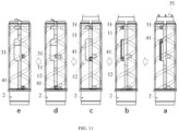
- FIGS. 11a and 11b illustrate the second descending stroke of the pushing cup descending along the second combined slideway
- FIGS. 11b to 11e illustrate the first descending stroke of the material cup and the pushing cup synchronously descending along the first combined slideway.
- FIG. 11 and the drawings of the cosmetic container and components thereof shown in the above-mentioned embodiments in FIG. 11 , when the material body 5 is used to the last part of the first part 51, the second lugs 41 of the pushing cup 4 are ascended to the top of the second slideway 22, and the first lugs 31 of the material cup 3 are locked in the material cup upper locking positions 302.
- the first lugs 31 of the material cup 3 and the second lugs 41 of the pushing cup 4 will be descended synchronously along the first slideway 21, entering into a state shown in FIG. 11d .
- the first lugs 31 and the second lugs 41 will be pushed to the material cup lower locking positions 301 and the pushing cup lower locking positions 401, respectively, making the material cup 3 and the pushing cup 4 enter a locked state, respectively, as shown in FIG. 11e .
- the first convex ribs 23 of the rotating member 2 and the second convex ribs of the material cup 3 will limit positions of the material cup 3 and the pushing cup 4, respectively.
- the second part 52 of the material body 5 exposed out of the material cup 3 is usually used firstly, after the second part 52 is used up, the first part 51 of the material body 5 placed in the material cup 3 will then be used.
- the first ascending stroke shown in FIGS. 10a to 10d and the first descending stroke shown in FIGS. 11a and 11b are alternately performed; and during the use process of the first part 51 of the material body 5, the ascending processes shown in FIG. 10 and the descending processes shown in FIG. 11 are alternately performed.
- the threaded sleeve 1 firstly assemble the threaded sleeve 1, the rotating member 2, the material cup 3, the pushing cup 4 and other components, then rotate the rotating member 2, make the material cup 3 and the pushing cup 4 enter into the state shown in FIG. 10d or 11b , and then insert the material body 5 in the material cup 3 to the pushing cup 4 supporting the material body 5.
- the first lugs 31 and the second lugs 41 can be stabilized by holding the threaded sleeve 1, so as to prevent the material cup 3 and the pushing cup 4 from loosening by force.
- the cosmetic container of the present disclosure has at least two strokes.
- the material cup 3 and the pushing cup 4 can be ascended and descended synchronously, and during the second stroke, the pushing cup 4 can be ascended and descended relative to the material cup 3, realizing that the material body 5 contained in the material cup 3 is completely used up, which improves the utilization rate of the material body 5, and the material body 5 can be made of soft materials flexibly according to needs, thereby improving the user experience.
- the area of the slideway pattern 20 can be reduced to ensure the firmness of the rotating member 2. Furthermore, with the third slideway 32 extending axially, on the one hand, the material cup 3 and the pushing cup 4 can be moved in the same direction, and on the other hand, the third slideway 32 can be respectively overlapped with the first slideway 21 and the second slideway of the slideway pattern 20, forming the first combined slideway for the material cup 3 and the pushing cup 4 to ascend and descend synchronously and the second combined slideway only for the pushing cup 4 to ascend and descend, which increases flexibility of the rotation of the material cup 3 and the pushing cup 4.
Landscapes
- Containers And Packaging Bodies Having A Special Means To Remove Contents (AREA)
- Cosmetics (AREA)
- Table Devices Or Equipment (AREA)
Applications Claiming Priority (2)
| Application Number | Priority Date | Filing Date | Title |
|---|---|---|---|
| CN202010316636.2A CN111449404B (zh) | 2020-04-21 | 2020-04-21 | 化妆品容器及其使用方法 |
| PCT/CN2021/088259 WO2021213350A1 (fr) | 2020-04-21 | 2021-04-20 | Récipient de maquillage et procédé d'utilisation de celui-ci |
Publications (2)
| Publication Number | Publication Date |
|---|---|
| EP4140357A1 true EP4140357A1 (fr) | 2023-03-01 |
| EP4140357A4 EP4140357A4 (fr) | 2024-01-03 |
Family
ID=71672014
Family Applications (1)
| Application Number | Title | Priority Date | Filing Date |
|---|---|---|---|
| EP21793610.3A Pending EP4140357A4 (fr) | 2020-04-21 | 2021-04-20 | Récipient de maquillage et procédé d'utilisation de celui-ci |
Country Status (5)
| Country | Link |
|---|---|
| US (1) | US12389998B2 (fr) |
| EP (1) | EP4140357A4 (fr) |
| JP (1) | JP7505027B2 (fr) |
| CN (1) | CN111449404B (fr) |
| WO (1) | WO2021213350A1 (fr) |
Families Citing this family (3)
| Publication number | Priority date | Publication date | Assignee | Title |
|---|---|---|---|---|
| WO2021139423A1 (fr) * | 2020-01-08 | 2021-07-15 | 有淳包装科技(上海)有限公司 | Tube de rouge à lèvres respectueux de l'environnement et recyclable à cent pour cent |
| CN112315169B (zh) | 2020-11-23 | 2025-04-29 | 有淳包装科技(上海)有限公司 | 一种可回收的环保口红管 |
| CN111449404B (zh) | 2020-04-21 | 2022-07-22 | 张大朋 | 化妆品容器及其使用方法 |
Family Cites Families (17)
| Publication number | Priority date | Publication date | Assignee | Title |
|---|---|---|---|---|
| US2429328A (en) * | 1944-11-17 | 1947-10-21 | Rault Anne-Marie Andre | Container with automatic ejecting device |
| US2895607A (en) * | 1956-10-30 | 1959-07-21 | Dulberg Murray | Holder with means for ejecting contents |
| JPS5995916U (ja) * | 1982-12-17 | 1984-06-29 | 竹内工業株式会社 | 口紅等の容器 |
| JPS6040211U (ja) * | 1983-08-25 | 1985-03-20 | カネボウ株式会社 | 繰り出し化粧棒容器 |
| JPH0346666Y2 (fr) * | 1986-02-25 | 1991-10-02 | ||
| US4991987A (en) * | 1990-01-23 | 1991-02-12 | Risdon Corporation | Cosmetic container |
| JP3197160B2 (ja) * | 1994-03-01 | 2001-08-13 | 有限会社日本アトゥー | 媒体用容器 |
| JP3522826B2 (ja) * | 1994-05-16 | 2004-04-26 | 株式会社ナリス化粧品 | 繰上式棒状化粧料容器 |
| JP3519475B2 (ja) * | 1994-12-26 | 2004-04-12 | 株式会社吉野工業所 | 棒状化粧料繰出容器 |
| US5842804A (en) * | 1996-03-28 | 1998-12-01 | Rexam Cosmetic Packaging, Inc. | Lipstick case with means for push-back prevention |
| US7157381B2 (en) | 2004-06-15 | 2007-01-02 | Infineon Technologies Ag | Method for providing whisker-free aluminum metal lines or aluminum alloy lines in integrated circuits |
| KR200408898Y1 (ko) * | 2005-12-05 | 2006-02-14 | 강성일 | 립스틱 용기 |
| FR3040127B1 (fr) * | 2015-08-18 | 2018-10-26 | Albea Services | Receptacle pour produit cosmetique, muni de moyens de deplacement telescopiques |
| CN107510217B (zh) * | 2017-10-24 | 2020-06-16 | 杨金英 | 一种唇膏容器 |
| CN211984252U (zh) * | 2020-04-21 | 2020-11-24 | 张大朋 | 化妆品容器 |
| CN111449404B (zh) * | 2020-04-21 | 2022-07-22 | 张大朋 | 化妆品容器及其使用方法 |
| US11779095B2 (en) * | 2021-12-09 | 2023-10-10 | Kr Co., Ltd. | Container for stick type content |
-
2020
- 2020-04-21 CN CN202010316636.2A patent/CN111449404B/zh active Active
-
2021
- 2021-04-20 EP EP21793610.3A patent/EP4140357A4/fr active Pending
- 2021-04-20 JP JP2022564296A patent/JP7505027B2/ja active Active
- 2021-04-20 US US17/995,935 patent/US12389998B2/en active Active
- 2021-04-20 WO PCT/CN2021/088259 patent/WO2021213350A1/fr not_active Ceased
Also Published As
| Publication number | Publication date |
|---|---|
| WO2021213350A1 (fr) | 2021-10-28 |
| JP7505027B2 (ja) | 2024-06-24 |
| US12389998B2 (en) | 2025-08-19 |
| JP2023527268A (ja) | 2023-06-28 |
| EP4140357A4 (fr) | 2024-01-03 |
| CN111449404A (zh) | 2020-07-28 |
| US20230210242A1 (en) | 2023-07-06 |
| CN111449404B (zh) | 2022-07-22 |
Similar Documents
| Publication | Publication Date | Title |
|---|---|---|
| EP4140357A1 (fr) | Récipient de maquillage et procédé d'utilisation de celui-ci | |
| US7228864B2 (en) | Cosmetic container | |
| CN205106740U (zh) | 一种膏体可用尽的口红管 | |
| US3989392A (en) | Dispensing device | |
| GB2173176A (en) | Dispenser for semi-solid material | |
| US11304496B2 (en) | Lipstick container | |
| US6079973A (en) | Apparatus for molding plastic caps | |
| US4984920A (en) | Closure assembly having an axially movable liquid dispenser | |
| EP1346661B1 (fr) | Distributeur de cosmétiques contenant une composition écran solaire | |
| US4990014A (en) | Closure assembly having a rotatable stem and an axially movable applicator brush | |
| CN211984252U (zh) | 化妆品容器 | |
| CN212465244U (zh) | 一种液体笔的推进结构及按压式液体笔 | |
| US6896434B2 (en) | Stick type cosmetic material feeding container | |
| US1999263A (en) | Lip stick and cosmetic container | |
| MXPA01002426A (es) | Lapiz labial y metodo para hacer el mismo. | |
| US4854758A (en) | Retractable applicator device for nail varnishes with flow control | |
| KR20090002581U (ko) | 화장품용기의 승강장치 | |
| KR102750134B1 (ko) | 잔여 내용물 방지 스틱형 화장품용기 | |
| US3191768A (en) | Material handling device | |
| JP2011143156A (ja) | 化粧材繰出容器 | |
| KR20110005880U (ko) | 고점도 내용물의 미세 정량토출이 가능한 펌프 용기 | |
| US11058206B2 (en) | Double-spiral lipstick tube | |
| CN210686886U (zh) | 一种多层伸缩杆 | |
| JP4838393B1 (ja) | 棒状化粧材繰出容器 | |
| KR102854057B1 (ko) | 잔여 내용물 방지 스틱형 화장품용기 |
Legal Events
| Date | Code | Title | Description |
|---|---|---|---|
| STAA | Information on the status of an ep patent application or granted ep patent |
Free format text: STATUS: THE INTERNATIONAL PUBLICATION HAS BEEN MADE |
|
| PUAI | Public reference made under article 153(3) epc to a published international application that has entered the european phase |
Free format text: ORIGINAL CODE: 0009012 |
|
| STAA | Information on the status of an ep patent application or granted ep patent |
Free format text: STATUS: REQUEST FOR EXAMINATION WAS MADE |
|
| 17P | Request for examination filed |
Effective date: 20221005 |
|
| AK | Designated contracting states |
Kind code of ref document: A1 Designated state(s): AL AT BE BG CH CY CZ DE DK EE ES FI FR GB GR HR HU IE IS IT LI LT LU LV MC MK MT NL NO PL PT RO RS SE SI SK SM TR |
|
| DAV | Request for validation of the european patent (deleted) | ||
| DAX | Request for extension of the european patent (deleted) | ||
| A4 | Supplementary search report drawn up and despatched |
Effective date: 20231201 |
|
| RIC1 | Information provided on ipc code assigned before grant |
Ipc: A45D 40/04 20060101AFI20231127BHEP |