EP4140385A1 - Reinigungsgerät - Google Patents
Reinigungsgerät Download PDFInfo
- Publication number
- EP4140385A1 EP4140385A1 EP21813931.9A EP21813931A EP4140385A1 EP 4140385 A1 EP4140385 A1 EP 4140385A1 EP 21813931 A EP21813931 A EP 21813931A EP 4140385 A1 EP4140385 A1 EP 4140385A1
- Authority
- EP
- European Patent Office
- Prior art keywords
- air duct
- branch
- air
- cooled condenser
- communication
- Prior art date
- Legal status (The legal status is an assumption and is not a legal conclusion. Google has not performed a legal analysis and makes no representation as to the accuracy of the status listed.)
- Granted
Links
Images



Classifications
-
- A—HUMAN NECESSITIES
- A47—FURNITURE; DOMESTIC ARTICLES OR APPLIANCES; COFFEE MILLS; SPICE MILLS; SUCTION CLEANERS IN GENERAL
- A47L—DOMESTIC WASHING OR CLEANING; SUCTION CLEANERS IN GENERAL
- A47L15/00—Washing or rinsing machines for crockery or tableware
- A47L15/42—Details
- A47L15/4291—Recovery arrangements, e.g. for the recovery of energy or water
-
- A—HUMAN NECESSITIES
- A47—FURNITURE; DOMESTIC ARTICLES OR APPLIANCES; COFFEE MILLS; SPICE MILLS; SUCTION CLEANERS IN GENERAL
- A47L—DOMESTIC WASHING OR CLEANING; SUCTION CLEANERS IN GENERAL
- A47L15/00—Washing or rinsing machines for crockery or tableware
- A47L15/0018—Controlling processes, i.e. processes to control the operation of the machine characterised by the purpose or target of the control
- A47L15/0047—Energy or water consumption, e.g. by saving energy or water
-
- A—HUMAN NECESSITIES
- A47—FURNITURE; DOMESTIC ARTICLES OR APPLIANCES; COFFEE MILLS; SPICE MILLS; SUCTION CLEANERS IN GENERAL
- A47L—DOMESTIC WASHING OR CLEANING; SUCTION CLEANERS IN GENERAL
- A47L15/00—Washing or rinsing machines for crockery or tableware
- A47L15/42—Details
- A47L15/4285—Water-heater arrangements
-
- A—HUMAN NECESSITIES
- A47—FURNITURE; DOMESTIC ARTICLES OR APPLIANCES; COFFEE MILLS; SPICE MILLS; SUCTION CLEANERS IN GENERAL
- A47L—DOMESTIC WASHING OR CLEANING; SUCTION CLEANERS IN GENERAL
- A47L15/00—Washing or rinsing machines for crockery or tableware
- A47L15/42—Details
- A47L15/48—Drying arrangements
- A47L15/488—Connections of the tub with the ambient air, e.g. air intake or venting arrangements
-
- A—HUMAN NECESSITIES
- A47—FURNITURE; DOMESTIC ARTICLES OR APPLIANCES; COFFEE MILLS; SPICE MILLS; SUCTION CLEANERS IN GENERAL
- A47L—DOMESTIC WASHING OR CLEANING; SUCTION CLEANERS IN GENERAL
- A47L2401/00—Automatic detection in controlling methods of washing or rinsing machines for crockery or tableware, e.g. information provided by sensors entered into controlling devices
- A47L2401/03—Operation mode, e.g. delicate washing, economy washing, reduced time, sterilizing, water softener regenerating, odor eliminating or service
-
- A—HUMAN NECESSITIES
- A47—FURNITURE; DOMESTIC ARTICLES OR APPLIANCES; COFFEE MILLS; SPICE MILLS; SUCTION CLEANERS IN GENERAL
- A47L—DOMESTIC WASHING OR CLEANING; SUCTION CLEANERS IN GENERAL
- A47L2501/00—Output in controlling method of washing or rinsing machines for crockery or tableware, i.e. quantities or components controlled, or actions performed by the controlling device executing the controlling method
- A47L2501/10—Air circulation, e.g. air intake or venting arrangements
Definitions
- the present disclosure relates to the field of electrical appliance manufacturing technologies, and more particularly, to a washing appliance.
- the washing appliance in the related art has a drying mode for drying tableware.
- a hot and humid airflow in a tub flows out from an outlet, passes through and is cooled down by an evaporator, and flows back to the tub after being reheated by an air-cooled condenser, to dry the tableware.
- a fan, the evaporator, and the air-cooled condenser are connected in series, the hot and humid airflow flowing out of the tub is cooled down by the evaporator and heated by the air-cooled condenser successively, which increases power consumption of the washing appliance.
- the present disclosure aims to solve at least one of the technical problems in the related art.
- the present disclosure provides a washing appliance, which has advantages of good drying effect on tableware, safe and reliable drying process, and low energy consumption.
- a washing appliance comprises: a tub comprising an air inlet and an air outlet; an air duct assembly comprising a first air duct, the first air duct comprising an inlet in communication with the air outlet and an outlet in communication with the air inlet; and a heat pump system comprising a compressor, a throttling device, an air-cooled condenser, and an evaporator.
- the evaporator is at least partially disposed in the first air duct.
- the air duct assembly further comprises a second air duct.
- the second air duct has an inlet in communication with the air outlet and an outlet in communication with the first air duct.
- the air-cooled condenser is at least partially disposed in the first air duct and located downstream of the second air duct in a gas flow direction.
- the washing appliance according to the embodiment of the present disclosure has advantages of good drying effect on tableware, safe and reliable drying process, low energy consumption, etc.
- washing appliance according to the above embodiment of the present disclosure can further have the following additional technical features.
- the first air duct comprises a main air duct, an inflow segment, and an outflow segment. Two ends of the main air duct are in communication with the inflow segment and the outflow segment respectively.
- the outlet of the second air duct is in communication with the outflow segment; and the air-cooled condenser is at least partially disposed in the outflow segment.
- the inlet of the second air duct is in communication with the inflow segment to allow the inlet of the second air duct to be in communication with the air outlet via the inflow segment; or the inflow segment and the inlet of the second air duct are respectively in direct communication with the air outlet.
- a flow cross-section area of the main air duct is greater than a flow cross-section area of the second air duct.
- the air duct assembly comprises a first vent and a second vent, the first vent and the second vent being respectively in communication with an ambient environment.
- the washing appliance further comprises a first switching member and a second switching member, the first switching member controls the main air duct to be or not to be in communication with the first vent or the inflow segment, and the second switching member is configured to control the main air duct to be or not to be in communication with the second vent or the outflow segment.
- the washing appliance further comprises a washing system.
- the heat pump system further comprises a water-cooled condenser heating a washing liquid in the washing system.
- the washing appliance has a drying state and a heating state. In the drying state of the washing appliance, the first switching member communicates the main air duct with the inflow segment and shuts the first vent, and the second switching member communicates the main air duct with the outflow segment and shuts the second vent. In the heating state of the washing appliance, the first switching member communicates the main air duct with the first vent and blocks the main air duct from the inflow segment, and the second switching member communicates the main air duct with the second vent and blocks the main air duct from the outflow segment.
- the washing appliance further comprises a washing system.
- the heat pump system further comprises a water-cooled condenser heating a washing liquid in the washing system.
- the compressor, the throttling device, the air-cooled condenser, the water-cooled condenser, and the evaporator are connected in series; and the water-cooled condenser is located upstream of the air-cooled condenser in a flow direction of a heat exchange medium in the heat pump system.
- the heat pump system comprises a first branch, a second branch, and a third branch, and two ends of the second branch and two ends of the third branch are respectively in communication with the first branch; the compressor, the evaporator, and the throttling device are connected in the first branch; the water-cooled condenser and a first on-off valve are connected in the second branch; and the air-cooled condenser and a second on-off valve are connected in the third branch.
- the throttling device comprises a first expansion valve and a second expansion valve
- the heat pump system comprises a first branch, a second branch, and a third branch, and two ends of second branch and two ends of the third branch are respectively in communication with the first branch
- the compressor and the evaporator are connected in the first branch
- the water-cooled condenser and the first expansion valve are connected in the second branch
- the air-cooled condenser and the second expansion valve are connected in the third branch.
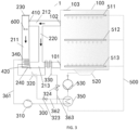
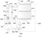
- washing appliance 1 tub 100, air inlet 101, air outlet 102, third vent 103, air duct assembly 200, first air duct 210, main air duct 211, inflow segment 212, outflow segment 213, second air duct 220, first vent 230, second vent 240, heat pump system 300, compressor 310, throttling device 320, first expansion valve 321, second expansion valve 322, first on-off valve 323, second on-off valve 324, air-cooled condenser 330, evaporator 340, water-cooled condenser 350, first branch 361, second branch 362, third branch 363, first switching member 410, second switching member 420, washing system 500, spray arm assembly 510, top spray arm 511, middle spray arm 512, lower spray arm 513, water collection member 520, washing pump 530, first fan 600.
- a washing appliance 1 according to embodiments of the present disclosure is described below with reference to the accompanying drawings.
- the washing appliance 1 according to an embodiment of the present disclosure comprises a tub 100, an air duct assembly 200, and a heat pump system 300.
- the tub 100 has an air inlet 101 and an air outlet 102.
- the air duct assembly 200 comprises a first air duct 210.
- the first air duct 210 has an inlet in communication with the air outlet 102 and an outlet in communication with the air inlet 101.
- the heat pump system 300 comprises a compressor 310, a throttling device 320, an air-cooled condenser 330, and an evaporator 340.
- the evaporator 340 is at least partially disposed in the first air duct 210 to facilitate heat exchange between the evaporator 340 and gas flowing through the evaporator 340.
- the air duct assembly 200 further comprises a second air duct 220.
- the second air duct 220 has an inlet in communication with the air outlet 102 and an outlet in communication with the first air duct 210.
- the air-cooled condenser 330 is at least partially disposed in the first air duct 210 and located downstream of the second air duct 220 in a gas flow direction to facilitate heat exchange between the air-cooled condenser 330 and gas flowing through the air-cooled condenser 330.
- a position at which the outlet of the second air duct 220 is communicated with the first air duct 210 is located upstream of the air-cooled condenser 330 and downstream of the evaporator 340. That is, the gas in the first air duct 210, after being subject to dehumidification of the evaporator 340, may merge with the gas in the second air duct 220. Both the gas in the first air duct 210 and the gas in the second air duct 220 are heated by the air-cooled condenser 330 before flowing into the tub 100 through the air inlet 101.
- the expression "the air-cooled condenser 330 is located downstream of the second air duct 220 in the gas flow direction” means that the gas flowing out of the tub 100 flows through the second air duct 220 before flowing through the air-cooled condenser 330.
- the expression "a position at which the outlet of the second air duct 220 is communicated with the first air duct 210 is located upstream of the air-cooled condenser 330 in the gas flow direction” means that the gas flowing out of the tub 100 flows through the position at which the outlet of the second air duct 220 is communicated with the first air duct 210 before flowing through the air-cooled condenser 330.
- the heat pump system 300 can be used to absorb heat from an external environment to heat the gas flowing in the air duct assembly 200 or a washing liquid in the washing appliance 1. That is, low-grade energy is converted into high-grade heat energy, and the high-grade heat energy is then released into the gas or the washing liquid, which achieves a purpose of efficient and low-energy heating.
- a refrigerant in the heat pump system 300 is subject to processes of compression, condensation and heat release, throttling expansion, evaporation and heat absorption, low-grade energy is converted into high-grade heat energy, and the high-grade heat energy is then released into the gas in the air duct assembly 200 or the washing liquid in the washing appliance 1, to achieve the purpose of efficient and low-energy heating.
- a manner has remarkable energy saving performance, and can significantly reduce energy consumption of the washing appliance 1.
- the highly humid gas flowing out of the tub 100 can flow into the first air duct 210 and the second air duct 220 through the air outlet 102.
- a part of the highly humid gas flows through the evaporator 340 in the first air duct 210, water vapor in the highly humid gas is condensed into a liquid state to reduce the humidity of the gas, which achieves drying and dehumidification of the gas.
- a temperature of the gas decreases accordingly, and the highly humid gas becomes dry and cold air.
- Another part of the highly humid gas can flow directly through the second air duct 220 and merge with the processed dry and cold air in the first air duct 210.
- the mixed gas flows through and is heated by the air-cooled condenser 330 and flows back to the tub 100 via the air inlet 101 to facilitate drying of tableware in the tub 100.
- the humidity and temperature of the highly humid gas flowing out of the tub 100 can be adjusted to allow the gas flowing back to the tub 100 to have a suitable temperature range and humidity range, which facilitates smooth drying of tableware inside the tub 100 by the gas and improves the drying performance of the washing appliance 1.
- a part of the gas flowing out of the tub 100 passes through the evaporator 340 and another part does not pass through the evaporator 340.
- the gas of the two parts is mixed before flowing through the air-cooled condenser 330 and enters the tub 100 via the air inlet 101.
- a total amount of the part of gas flowing through the evaporator 340 is controlled, which facilitates control of the humidity and temperature of the gas flowing back to the tub 100, and improves a dehumidification capacity of the gas per unit.
- the washing appliance 1 according to the embodiments of the present disclosure has advantages of good drying effect on tableware, safe and reliable drying process, and low energy consumption.
- washing appliance 1 according to specific embodiments of the present disclosure is described below with reference to the accompanying drawings.
- the washing appliance 1 according to the embodiments of the present disclosure, comprises the tub 100, the air duct assembly 200, and the heat pump system 300.
- the first air duct 210 comprises a main air duct 211, an inflow segment 212, and an outflow segment 213.
- the main air duct 211 has two ends and the two ends are in communication with the inflow segment 212 and the outflow segment 213 respectively.
- the outlet of the second air duct 220 is in communication with the outflow segment 213.
- the air-cooled condenser 330 is at least partially disposed in the outflow segment 213.
- first air duct 210 it is not only convenient for the first air duct 210 to be communicated with the tub 100 via the inlet and the outlet to form a circulation loop, but also convenient for the gas in the first air duct 210 and the gas in the second air duct 220 to merge with each other and then flow through the air-cooled condenser 330 to be heated.
- the first air duct 210 comprises the main air duct 211, the inflow segment 212, and the outflow segment 213.
- the main air duct 211 has the two ends in communication with the inflow segment 212 and the outflow segment 213 respectively.
- the inlet of the first air duct 210 is formed on the inflow segment 212.
- the inflow segment 212 is in communication with the air outlet 102 through the inlet of the first air duct 210.
- the outlet of the first air duct 210 is formed on the outflow segment 213.
- the outflow segment 213 is in communication with the air inlet 101 through the outlet of the first air duct 210.
- the evaporator 340 is disposed in the main air duct 211 or the outflow segment 213.
- the inlet of the second air duct 220 is in communication with the first air duct 210.
- the outlet of the second air duct 220 is in communication with the outflow segment 213.
- the air-cooled condenser 330 is at least partially disposed in the outflow segment 213.
- a connection of the second air duct 220 and the outflow segment 213 is located upstream of the air-cooled condenser 330, and a connection of the second air duct 220 and the outflow segment 213 is located downstream of the evaporator 340. That is, the gas in the first air duct 210 flows through the air-cooled condenser 330 after flowing through the evaporator 340, and then flows back to the tub 100. The gas in the second air duct 220 flows back to the tub 100 after flowing through the air-cooled condenser 330.
- the inlet of the second air duct 220 is in communication with the inflow segment 212 to allow the inlet of the second air duct 220 to be in communication with the air outlet 102 via the inflow segment 212.
- the highly humid gas in the tub 100 can be guided, via the inflow segment 212, to the main air duct 211 of the first air duct 210 and the second air duct 220, in such a manner that the first air duct 210 and the second air duct 220 are in communication with the tub 100 to form a circulation loop.
- the inflow segment 212 and the inlet of the second air duct 220 are respectively in direct communication with the air outlet 102. In this way, the highly humid gas in the tub 100 can flow into each of the first air duct 210 and the second air duct 220 separately to prevent normal flow of the gas from being affected by mutual interference of the gas in the first air duct 210 and the gas in the second air duct 220.
- a flow cross-section area of the main air duct 211 is greater than a flow cross-section area of the second air duct 220. In this way, it can be ensured that most of the highly humid gas flowing out of the tub 100 can pass through the evaporator 340 for drying and dehumidification, which facilitates a reduction of humidity of the gas and improves the drying performance of the gas on the tableware.
- the air duct assembly 200 comprises a first vent 230 and a second vent 240.
- the first vent 230 and the second vent 240 are respectively in communication with an ambient environment.
- the washing appliance 1 further comprises a first switching member 410 and a second switching member 420.
- the first switching member 410 is configured to control the main air duct 211 to be or not to be in communication with the first vent 230 or the inflow segment 212.
- the second switching member 420 is configured to control the main air duct 211 to be or not to be in communication with the second vent 240 or the outflow segment 213.
- the main air duct 211 of the first air duct 210 can be in communication with the external environment or the tub 100 to form a circulation loop as desired, which is convenient to enhance circulation flexibility of the gas circulating in the first air duct 210 and improve functionality and applicability of the air duct assembly 200.
- first vent 230 and the second vent 240 may be disposed at positions of a side panel, a skirting board, or a housing of the washing appliance 1 that are not obscured by a cabinet or an external object.
- the air inlet 101 and the air outlet 102 may be disposed on positions of a side wall surface or a top surface of the tub 100 that are easily accessible to the tub 100.
- the washing appliance 1 further comprises a washing system 500.
- the heat pump system 300 further comprises a water-cooled condenser 350 configured to heat a washing liquid in the washing system 500.
- the washing appliance 1 has a drying state and a heating state. In the drying state of the washing appliance 1, the first switching member 410 communicates the main air duct 211 with the inflow segment 212 and shuts the first vent 230, and the second switching member 420 communicates the main air duct 211 with the outflow segment 213 and shuts the second vent 240.
- the first switching member 410 communicates the main air duct 211 with the first vent 230 and blocks the main air duct 211 from the inflow segment 212
- the second switching member 420 communicates the main air duct 211 with the second vent 240 and blocks the main air duct 211 from the outflow segment 213.
- the air duct assembly 200 can form an inner circulation with the tub 100 to facilitate drying and dehumidification of the highly humid gas flowing out of the tub 100, which can not only improve the drying performance of the washing appliance 1, but also prevent the dust in the external environment from entering the tub 100 and causing pollution to the tub 100 and the tableware.
- the air duct assembly 200 can be in communication with the external environment to facilitate the evaporator 340 to collect heat from air in the external environment, which improves the heating efficiency of the heat pump system 300, and enhances washing performance of the washing appliance 1.
- the evaporator 340 is disposed in the main air duct 211.
- two ends of the main air duct 211 can be in communication with the external environment through the first vent 230 and the second vent 240 respectively, by means of the first switching member 410 and the second switching member 420, to allow the air in the external environment to continuously flow through the evaporator 340, which facilitates the evaporator 340 to absorb the heat of the air in the external environment.
- the two ends of the main air duct 211 can be in communication with the inflow segment 212 and the outflow segment 213 respectively, by means of the first switching member 410 and the second switching member 420, to form an inner circulation loop between the air duct assembly 200 and the tub 100, in such a manner that drying and dehumidification can be performed, using the evaporator 340, on the highly humid gas flowing out of the tub 100, and the dried and dehumidified gas flows back to the tub 100 to dry the tableware.
- the washing appliance 1 further comprises the washing system 500.
- the heat pump system 300 comprises the water-cooled condenser 350 configured to heat the washing liquid in the washing system 500.
- the water-cooled condenser 350 can be used to heat the washing liquid in the washing system 500.
- the high-temperature washing liquid washes away contaminants on the tableware and brings heat to the tableware to allow the washing appliance 1 to obtain a high abluent rate and a dry rate in a short washing period.
- the compressor 310, the throttling device 320, the air-cooled condenser 330, the water-cooled condenser 350, and the evaporator 340 are connected in series.
- the water-cooled condenser 350 is located upstream of the air-cooled condenser 330 in a flow direction of a heat exchange medium in the heat pump system 300. In this way, after absorbing heat, the heat exchange medium flows through the water-cooled condenser 350 and then flows through the air-cooled condenser 330, which can ensure that the heat pump system 300 preferentially heats the washing liquid in the washing system 500 using the water-cooled condenser 350. Therefore, the washing performance of the washing appliance 1 is guaranteed.
- the expression "the water-cooled condenser 350 is located upstream of the air-cooled condenser 330 in a flow direction of a heat exchange medium in the heat pump system 300" means that after absorbing heat through the evaporator 340, the heat exchange medium flows through the water-cooled condenser 350 and then flows through the air-cooled condenser 330.
- the evaporator 340, the compressor 310, the water-cooled condenser 350, the air-cooled condenser 330, and the throttling device 320 are connected sequentially in series to form a circulation loop.
- the throttling device 320 may be an expansion valve. Further, the throttling device 320 may be an electronic expansion valve.
- the heat pump system 300 comprises a first branch 361, a second branch 362, and a third branch 363. Two ends of the second branch 362 and two ends of the third branch 363 are respectively in communication with the first branch 361.
- the compressor 310, the evaporator 340, and the throttling device 320 are connected in the first branch 361.
- the water-cooled condenser 350 and a first on-off valve 323 are connected in the second branch 362.
- the air-cooled condenser 330 and a second on-off valve 324 are connected in the third branch 363. In this way, when the heat pump system 300 heats the washing liquid, the first on-off valve 323 can be opened and the second on-off valve 324 can be closed.
- no heat exchange medium flows in the third branch 363, which can reduce flowing resistance in pipelines of the heat pump system 300 and reduce energy consumption of the heat pump system 300 when heating the washing liquid.
- the second on-off valve 324 can be opened and the first on-off valve 323 can be closed.
- no heat exchange medium flows in the second branch 362, which can reduce the flowing resistance in the pipelines of the heat pump system 300, and reduce energy consumption of the heat pump system 300 at the stage of drying or storing the tableware. Therefore, an energy efficiency of the washing appliance 1 can be increased to reduce the energy consumption.
- the throttling device 320 comprises a first expansion valve 321 and a second expansion valve 322.
- the heat pump system 300 comprises a first branch 361, a second branch 362, and a third branch 363. Two ends of the second branch 362 and two ends of the third branch 363 are respectively in communication with the first branch 361.
- the compressor 310 and the evaporator 340 are connected in the first branch 361.
- the water-cooled condenser 350 and the first expansion valve 321 are connected in the second branch 362.
- the air-cooled condenser 330 and the second expansion valve 322 are connected in the third branch 363. In this way, a dual throttling device 320 system can be formed using the first expansion valve 321 and the second expansion valve 322.
- the first expansion valve 321 When the heat pump system 300 heats the washing liquid, the first expansion valve 321 enters a normal operation state, and the second expansion valve 322 is closed completely or in a state with a minimum opening. In this case, no heat exchange medium flows in the third branch 363, which can reduce the flowing resistance in the pipelines of the heat pump system 300 and reduce energy consumption of the heat pump system 300 when heating the washing liquid.
- the second expansion valve 322 At a stage of drying or storing the tableware, the second expansion valve 322 enters a normal operation state, and the first expansion valve 321 is closed completely or in a state with a minimum opening.
- the washing system 500 comprises a spray arm assembly 510, a water collection member 520, and a washing pump 530.
- the spray arm assembly 510 is disposed in the tub 100.
- the water collection member 520 is disposed in the tub 100 and located below the spray arm assembly 510 (an up-down direction of the tub 100 is as illustrated in FIG. 1 ).
- the washing pump 530 is in communication with the spray arm assembly 510 and the water collection member 520 respectively. In this way, the washing pump 530 can be used to deliver the washing liquid in the washing system 500 to the spray arm assembly 510.
- the spray arm assembly 510 can be used to continuously impose jet washing on the tableware to achieve a purpose of cleaning the tableware.
- the water collection member 520 can collect the washing liquid in the tub 100 to achieve circulation and flowing of the washing liquid in the washing system 500.
- the spray arm assembly 510 comprises a top spray arm 511, a middle spray arm 512, and a lower spray arm 513.
- the water collection member 520 is formed as a water-cup collection tank located in a lower part of the tub 100.
- a first fan 600 is provided in the first air duct 210.
- the first fan 600 is located upstream of the evaporator 340 in the gas flow direction. In this way, under the action of the first fan 600, the gas can flow through the evaporator 340 smoothly to increase a ventilation quantity in the air duct assembly 200 and improve a heat exchange efficiency of the heat pump system 300.
- the first fan 600 is disposed in the main air duct 211 of the first air duct 210.
- the tub 100 has a third vent 103.
- the third vent 103 is in communication with the external environment and located at a top end of the tub 100.
- a movable seal is disposed at the third vent 103.
- the seal is pushed away to expose the third vent 103, in which case the third vent 103 is in communication with the tub 100, and the gas inside the tub 100 can be discharged to the external environment via the third vent 103.
- the seal seals the third vent 103 to form a sealed space inside the tub 100.
- the compressor 310 in the heat pump system 300 operates to pump the high-temperature and high-pressure heat exchange medium to the water-cooled condenser 350 to heat the washing liquid in the washing system 500.
- the heat exchange medium flows out of the water-cooled condenser 350 after exchanging heat with the washing liquid, and then flows into the air-cooled condenser 330.
- the heat exchange medium becomes a low-temperature and low-pressure heat exchange medium which then flows into the evaporator 340.
- the heat exchange medium exchanges heat with the gas in the evaporator 340, and then flows back to the compressor 310 to complete a heating cycle of the whole heat pump system 300.
- the washing pump 530 operates to pump the washing liquid from the water collection member 520 to the water-cooled condenser 350 in the heat pump system 300 to heat the washing liquid, and then supplies the heated washing liquid to the spray arm assembly 510 to wash the tableware.
- the first fan 600 is activated, the first switching member 410 communicates the main air duct 211 with the first vent 230, and the second switching member 420 communicates the main air duct 211 with the second vent 240.
- the air in the external environment flows from the first vent 230 into the main air duct 211, flows through the evaporator 340, and is then discharged from the second vent 240.
- the first fan 600 when the washing appliance 1 is in the drying state for drying the tableware, the first fan 600 is activated, and the compressor 310 in the heat pump system 300 is also activated.
- the high-temperature and high-pressure heat exchange medium is pumped by the compressor 310 to the water-cooled condenser 350 to dry internal components of the water-cooled condenser 350 and the washing system 500, and then flows into the air-cooled condenser 330 to circulate and heat the gas in the tub 100. Therefore, faster evaporation and drying of water droplets on the tableware can be realized and a temperature of the tableware per se can be increased.
- the heat exchange medium that has undergone the condensation by the air-cooled condenser 330 is throttled by the throttling device 320 and then flows into the air-cooled evaporator 340.
- the highly humid gas in the tub 100 flows into the air duct assembly 200 via the air outlet 102.
- a part of the highly humid gas passes through and is cooled and dehumidified in the air-cooled evaporator 340, and is then mixed with the other part of the highly humid gas that has not passed through the evaporator 340.
- the mixed gas flows towards the air-cooled condenser 330, and then enters the tub 100 via the air inlet 101 to be mixed with high-temperature and high-humidity gas in the tub 100 or to squeeze out the high-temperature and high-humidity gas from the air outlet 102.
- the above processes are cycled to achieve humidity reduction of the gas in the tub 100, improving the drying efficiency and shortening the drying time.
- the washing appliance 1 comprises the tub 100, the air duct assembly 200, and the heat pump system 300.
- the tub 100 has the air inlet 101 and the air outlet 102.
- the air duct assembly 200 comprises the first air duct 210.
- the inlet of the first air duct 210 is in communication with the air outlet 102.
- the outlet of the first air duct 210 is in communication with the air inlet 101.
- the heat pump system 300 comprises the compressor 310, the throttling device 320, the air-cooled condenser 330, and the evaporator 340.
- the evaporator 340 is at least partially disposed in the first air duct 210.
- the air duct assembly 200 further comprises the second air duct 220.
- the inlet of the second air duct 220 is in communication with the air outlet 102.
- the outlet of the second air duct 220 is in communication with the first air duct 210.
- the air-cooled condenser 330 is at least partially disposed in the first air duct 210 and located downstream of the second air duct 220 in the gas flow direction.
- the first air duct 210 comprises the main air duct 211, the inflow segment 212, and the outflow segment 213.
- the two ends of the main air duct 211 are in communication with the inflow segment 212 and the outflow segment 213 respectively.
- the outlet of the second air duct 220 is in communication with the outflow segment 213.
- the air-cooled condenser 330 is at least partially disposed in the outflow segment 213.
- the inlet of the second air duct 220 is in communication with the inflow segment 212 to allow the inlet of the second air duct 220 to be in communication with the air outlet 102 via the inflow segment 212.
- the flow cross-section area of the main air duct 211 is greater than the flow cross-section area of the second air duct 220.
- the air duct assembly 200 comprises the first vent 230 and the second vent 240.
- the first vent 230 and the second vent 240 are respectively in communication with the ambient environment.
- the washing appliance 1 further comprises the first switching member 410 and the second switching member 420.
- the first switching member 410 is configured to control the main air duct 211 to be or not to be in communication with the first vent 230 or the inflow segment 212.
- the second switching member 420 is configured to control the main air duct 211 to be or not to be in communication with the second vent 240 or the outflow segment 213.
- the washing appliance 1 further comprises the washing system 500.
- the heat pump system 300 further comprises the water-cooled condenser 350 configured to heat the washing liquid in the washing system 500.
- the washing appliance 1 has the drying state and the heating state. In the drying state of the washing appliance 1, the first switching member 410 communicates the main air duct 211 with the inflow segment 212 and shuts the first vent 230, and the second switching member 420 communicates the main air duct 211 with the outflow segment 213 and shuts the second vent 240.
- the first switching member 410 communicates the main air duct 211 with the first vent 230 and blocks the main air duct 211 from the inflow segment 212
- the second switching member 420 communicates the main air duct 211 with the second vent 240 and blocks the main air duct 211 from the outflow segment 213.
- the compressor 310, the throttling device 320, the air-cooled condenser 330, the water-cooled condenser 350, and the evaporator 340 are connected in series.
- the water-cooled condenser 350 is located upstream of the air-cooled condenser 330 in the flow direction of the heat exchange medium in the heat pump system 300.
- the heat pump system 300 comprises the first branch 361, the second branch 362, and the third branch 363. Two ends of the second branch 362 and two ends of the third branch 363 are respectively in communication with the first branch 361.
- the compressor 310, the evaporator 340, and the throttling device 320 are connected in the first branch 361.
- the water-cooled condenser 350 and the first on-off valve 323 are connected in the second branch 362.
- the air-cooled condenser 330 and the second on-off valve 324 are connected in the third branch 363.
- the throttling device 320 comprises the first expansion valve 321 and the second expansion valve 322.
- the heat pump system 300 comprises the first branch 361, the second branch 362, and the third branch 363. Two ends of the second branch 362 and two ends of the third branch 363 are respectively in communication with the first branch 361.
- the compressor 310 and the evaporator 340 are connected in the first branch 361.
- the water-cooled condenser 350 and the first expansion valve 321 are connected in the second branch 362.
- the air-cooled condenser 330 and the second expansion valve 322 are connected in the third branch 363.
- the washing system 500 comprises the spray arm assembly 510, the water collection member 520, and the washing pump 530.
- the spray arm assembly 510 is disposed in the tub 100.
- the water collection member 520 is disposed in the tub 100 and located below the spray arm assembly 510.
- the washing pump 530 is in communication with the spray arm assembly 510 and the water collection member 520 respectively.
- the spray arm assembly 510 comprises the top spray arm 511, the middle spray arm 512, and the lower spray arm 513.
- the water collection member 520 is formed as the water-cup collection tank located in the lower part of the tub 100.
- the first fan 600 is provided in the first air duct 210.
- the first fan 600 is located upstream of the evaporator 340 in the gas flow direction.
- the first fan 600 is disposed in the main air duct 211 of the first air duct 210.
- the tub 100 has the third vent 103.
- the third vent 103 is in communication with the external environment and located at the top end of the tub 100.
- the movable seal is disposed at the third vent 103.
- the seal is pushed away to expose the third vent 103, in which case the third vent 103 is in communication with the tub 100, and the gas inside the tub 100 can be discharged to the external environment via the third vent 103.
- the seal seals the third vent 103.
- washing appliance 1 According to the embodiments of the present disclosure are known to those skilled in the art and are not described in detail here.
- first and second may explicitly or implicitly comprise at least one of the features.
- plural means two or more, unless otherwise specifically defined.
- first feature "on” or “under” the second feature may mean that the first feature is in direct contact with the second feature, or the first and second features are in indirect contact through another feature between them.
- the first feature "above" the second feature may mean that the first feature is directly above or obliquely above the second feature, or simply mean that the level of the first feature is higher than that of the second feature.
Landscapes
- Detail Structures Of Washing Machines And Dryers (AREA)
- Washing And Drying Of Tableware (AREA)
Applications Claiming Priority (2)
| Application Number | Priority Date | Filing Date | Title |
|---|---|---|---|
| CN202020945940.9U CN212591996U (zh) | 2020-05-28 | 2020-05-28 | 洗涤电器 |
| PCT/CN2021/096869 WO2021239125A1 (zh) | 2020-05-28 | 2021-05-28 | 洗涤电器 |
Publications (3)
| Publication Number | Publication Date |
|---|---|
| EP4140385A1 true EP4140385A1 (de) | 2023-03-01 |
| EP4140385A4 EP4140385A4 (de) | 2023-10-18 |
| EP4140385B1 EP4140385B1 (de) | 2025-07-23 |
Family
ID=74750289
Family Applications (1)
| Application Number | Title | Priority Date | Filing Date |
|---|---|---|---|
| EP21813931.9A Active EP4140385B1 (de) | 2020-05-28 | 2021-05-28 | Reinigungsgerät |
Country Status (3)
| Country | Link |
|---|---|
| EP (1) | EP4140385B1 (de) |
| CN (1) | CN212591996U (de) |
| WO (1) | WO2021239125A1 (de) |
Cited By (1)
| Publication number | Priority date | Publication date | Assignee | Title |
|---|---|---|---|---|
| EP4595860A1 (de) * | 2024-01-31 | 2025-08-06 | Zhejiang Sanhua Intelligent Controls Co.,Ltd | Geschirrspülerwärmepumpenvorrichtung und geschirrspüler |
Families Citing this family (7)
| Publication number | Priority date | Publication date | Assignee | Title |
|---|---|---|---|---|
| CN212591996U (zh) * | 2020-05-28 | 2021-02-26 | 佛山市顺德区美的洗涤电器制造有限公司 | 洗涤电器 |
| KR20240001344A (ko) * | 2022-06-24 | 2024-01-03 | 엘지전자 주식회사 | 열펌프장치를 포함하는 식기세척기 |
| CN120391951A (zh) * | 2024-02-01 | 2025-08-01 | 佛山市顺德区美的洗涤电器制造有限公司 | 清洁设备 |
| CN121221026A (zh) * | 2024-06-28 | 2025-12-30 | 芜湖美的厨卫电器制造有限公司 | 洗碗机及其控制方法 |
| CN223183500U (zh) * | 2024-07-31 | 2025-08-05 | 佛山市顺德区美的洗涤电器制造有限公司 | 洗涤电器 |
| WO2026026174A1 (zh) * | 2024-07-31 | 2026-02-05 | 佛山市顺德区美的洗涤电器制造有限公司 | 洗涤电器 |
| CN223081634U (zh) * | 2024-07-31 | 2025-07-11 | 佛山市顺德区美的洗涤电器制造有限公司 | 洗涤电器 |
Family Cites Families (10)
| Publication number | Priority date | Publication date | Assignee | Title |
|---|---|---|---|---|
| DE102008044284A1 (de) * | 2008-12-02 | 2010-06-10 | BSH Bosch und Siemens Hausgeräte GmbH | Trockner mit Umluftanteil sowie Verfahren zu seinem Betrieb |
| KR102094340B1 (ko) * | 2014-03-17 | 2020-03-30 | 삼성전자주식회사 | 건조장치를 구비하는 가전제품 |
| DE102014118791A1 (de) * | 2014-12-17 | 2016-06-23 | Miele & Cie. Kg | Vorrichtung und Verfahren zum Bereitstellen von Heizleistung für ein Wäschebehandlungsgerät und Wäschebehandlungsgerät |
| CN106264409B (zh) * | 2016-09-05 | 2019-01-18 | 佛山市顺德区美的洗涤电器制造有限公司 | 洗碗机的干燥系统及洗碗机 |
| US10758108B2 (en) * | 2018-01-10 | 2020-09-01 | Haier Us Appliance Solutions, Inc. | Heating assembly for a washing appliance |
| CN108403062B (zh) * | 2018-05-17 | 2023-09-26 | 佛山市顺德区美的洗涤电器制造有限公司 | 干燥系统和洗涤电器 |
| CN108888215A (zh) * | 2018-06-08 | 2018-11-27 | 广东美的厨房电器制造有限公司 | 洗涤电器 |
| EP3851016A4 (de) * | 2018-09-14 | 2021-11-10 | Foshan Shunde Midea Washing Appliances Manufacturing Co., Ltd. | Geschirrspülmaschine |
| CN209315776U (zh) * | 2018-09-14 | 2019-08-30 | 佛山市顺德区美的洗涤电器制造有限公司 | 洗涤电器 |
| CN212591996U (zh) * | 2020-05-28 | 2021-02-26 | 佛山市顺德区美的洗涤电器制造有限公司 | 洗涤电器 |
-
2020
- 2020-05-28 CN CN202020945940.9U patent/CN212591996U/zh active Active
-
2021
- 2021-05-28 WO PCT/CN2021/096869 patent/WO2021239125A1/zh not_active Ceased
- 2021-05-28 EP EP21813931.9A patent/EP4140385B1/de active Active
Cited By (1)
| Publication number | Priority date | Publication date | Assignee | Title |
|---|---|---|---|---|
| EP4595860A1 (de) * | 2024-01-31 | 2025-08-06 | Zhejiang Sanhua Intelligent Controls Co.,Ltd | Geschirrspülerwärmepumpenvorrichtung und geschirrspüler |
Also Published As
| Publication number | Publication date |
|---|---|
| WO2021239125A1 (zh) | 2021-12-02 |
| EP4140385B1 (de) | 2025-07-23 |
| EP4140385A4 (de) | 2023-10-18 |
| CN212591996U (zh) | 2021-02-26 |
Similar Documents
| Publication | Publication Date | Title |
|---|---|---|
| EP4140385B1 (de) | Reinigungsgerät | |
| US20110259025A1 (en) | Heat pump type speed heating apparatus | |
| CN107490283B (zh) | 可快速升温的热回收型调温热泵干燥装置及其运行方法 | |
| CN107724027B (zh) | 干衣机 | |
| EP3026168B1 (de) | Wäschetrocknervorrichtung | |
| CN102401519B (zh) | 空调器的室外机 | |
| CN109306611B (zh) | 一种具有室内温度调节功能的衣物处理设备及其控制方法 | |
| CN111110155B (zh) | 一种热泵式洗碗机及其控制方法 | |
| CN109077688B (zh) | 洗涤电器 | |
| EP3184934B1 (de) | Wärmepumpensystem, wäscher-trockner-kombination und trockner | |
| CN110260605B (zh) | 一种全热回收和除湿回热联合的烘干房 | |
| CN109383228B (zh) | 一种热泵空调器及其控制方法 | |
| WO2020052332A1 (zh) | 洗涤电器 | |
| CN104727111B (zh) | 一种干衣机及控制方法 | |
| CN106524581B (zh) | 一种单压缩机双蒸发温度的无霜型热回收式新风热泵机组 | |
| KR100946381B1 (ko) | 하이브리드 히트펌프식 냉난방장치 | |
| CN111692779A (zh) | 一种用于海苔烘干的湿冷双效回收型高效热泵机组 | |
| CN207990944U (zh) | 一种移动除湿烘干冷暖空调机 | |
| CN209153559U (zh) | 洗涤电器 | |
| CN103103736A (zh) | 基于co2跨临界热泵循环系统的衣物干燥系统 | |
| WO2013075997A1 (en) | A laundry dryer with a heat pump system | |
| CN114152038B (zh) | 一种除湿装置、烘干设备及除湿方法 | |
| CN117248360A (zh) | 一种衣物护理设备及衣物护理方法 | |
| CN212205138U (zh) | 热交换系统和电器设备 | |
| CN102538299B (zh) | 热泵式可调温湿度机组 |
Legal Events
| Date | Code | Title | Description |
|---|---|---|---|
| STAA | Information on the status of an ep patent application or granted ep patent |
Free format text: STATUS: THE INTERNATIONAL PUBLICATION HAS BEEN MADE |
|
| PUAI | Public reference made under article 153(3) epc to a published international application that has entered the european phase |
Free format text: ORIGINAL CODE: 0009012 |
|
| STAA | Information on the status of an ep patent application or granted ep patent |
Free format text: STATUS: REQUEST FOR EXAMINATION WAS MADE |
|
| 17P | Request for examination filed |
Effective date: 20221123 |
|
| AK | Designated contracting states |
Kind code of ref document: A1 Designated state(s): AL AT BE BG CH CY CZ DE DK EE ES FI FR GB GR HR HU IE IS IT LI LT LU LV MC MK MT NL NO PL PT RO RS SE SI SK SM TR |
|
| DAV | Request for validation of the european patent (deleted) | ||
| DAX | Request for extension of the european patent (deleted) | ||
| A4 | Supplementary search report drawn up and despatched |
Effective date: 20230914 |
|
| RIC1 | Information provided on ipc code assigned before grant |
Ipc: A47L 15/00 20060101ALN20230908BHEP Ipc: A47L 15/48 20060101ALI20230908BHEP Ipc: A47L 15/42 20060101ALI20230908BHEP Ipc: A47L 15/14 20060101AFI20230908BHEP |
|
| GRAP | Despatch of communication of intention to grant a patent |
Free format text: ORIGINAL CODE: EPIDOSNIGR1 |
|
| STAA | Information on the status of an ep patent application or granted ep patent |
Free format text: STATUS: GRANT OF PATENT IS INTENDED |
|
| RIC1 | Information provided on ipc code assigned before grant |
Ipc: A47L 15/00 20060101ALN20250328BHEP Ipc: A47L 15/48 20060101ALI20250328BHEP Ipc: A47L 15/42 20060101ALI20250328BHEP Ipc: A47L 15/14 20060101AFI20250328BHEP |
|
| INTG | Intention to grant announced |
Effective date: 20250409 |
|
| GRAS | Grant fee paid |
Free format text: ORIGINAL CODE: EPIDOSNIGR3 |
|
| GRAA | (expected) grant |
Free format text: ORIGINAL CODE: 0009210 |
|
| STAA | Information on the status of an ep patent application or granted ep patent |
Free format text: STATUS: THE PATENT HAS BEEN GRANTED |
|
| AK | Designated contracting states |
Kind code of ref document: B1 Designated state(s): AL AT BE BG CH CY CZ DE DK EE ES FI FR GB GR HR HU IE IS IT LI LT LU LV MC MK MT NL NO PL PT RO RS SE SI SK SM TR |
|
| REG | Reference to a national code |
Ref country code: GB Ref legal event code: FG4D |
|
| REG | Reference to a national code |
Ref country code: CH Ref legal event code: EP |
|
| REG | Reference to a national code |
Ref country code: DE Ref legal event code: R096 Ref document number: 602021034754 Country of ref document: DE |
|
| REG | Reference to a national code |
Ref country code: IE Ref legal event code: FG4D |
|
| REG | Reference to a national code |
Ref country code: NL Ref legal event code: FP |
|
| PG25 | Lapsed in a contracting state [announced via postgrant information from national office to epo] |
Ref country code: PT Free format text: LAPSE BECAUSE OF FAILURE TO SUBMIT A TRANSLATION OF THE DESCRIPTION OR TO PAY THE FEE WITHIN THE PRESCRIBED TIME-LIMIT Effective date: 20251124 |
|
| REG | Reference to a national code |
Ref country code: AT Ref legal event code: MK05 Ref document number: 1815506 Country of ref document: AT Kind code of ref document: T Effective date: 20250723 |
|
| PG25 | Lapsed in a contracting state [announced via postgrant information from national office to epo] |
Ref country code: IS Free format text: LAPSE BECAUSE OF FAILURE TO SUBMIT A TRANSLATION OF THE DESCRIPTION OR TO PAY THE FEE WITHIN THE PRESCRIBED TIME-LIMIT Effective date: 20251123 |
|
| PG25 | Lapsed in a contracting state [announced via postgrant information from national office to epo] |
Ref country code: NO Free format text: LAPSE BECAUSE OF FAILURE TO SUBMIT A TRANSLATION OF THE DESCRIPTION OR TO PAY THE FEE WITHIN THE PRESCRIBED TIME-LIMIT Effective date: 20251023 |
|
| REG | Reference to a national code |
Ref country code: LT Ref legal event code: MG9D |
|
| PG25 | Lapsed in a contracting state [announced via postgrant information from national office to epo] |
Ref country code: AT Free format text: LAPSE BECAUSE OF FAILURE TO SUBMIT A TRANSLATION OF THE DESCRIPTION OR TO PAY THE FEE WITHIN THE PRESCRIBED TIME-LIMIT Effective date: 20250723 |
|
| PG25 | Lapsed in a contracting state [announced via postgrant information from national office to epo] |
Ref country code: FI Free format text: LAPSE BECAUSE OF FAILURE TO SUBMIT A TRANSLATION OF THE DESCRIPTION OR TO PAY THE FEE WITHIN THE PRESCRIBED TIME-LIMIT Effective date: 20250723 |
|
| PG25 | Lapsed in a contracting state [announced via postgrant information from national office to epo] |
Ref country code: HR Free format text: LAPSE BECAUSE OF FAILURE TO SUBMIT A TRANSLATION OF THE DESCRIPTION OR TO PAY THE FEE WITHIN THE PRESCRIBED TIME-LIMIT Effective date: 20250723 |
|
| PG25 | Lapsed in a contracting state [announced via postgrant information from national office to epo] |
Ref country code: GR Free format text: LAPSE BECAUSE OF FAILURE TO SUBMIT A TRANSLATION OF THE DESCRIPTION OR TO PAY THE FEE WITHIN THE PRESCRIBED TIME-LIMIT Effective date: 20251024 |
|
| PG25 | Lapsed in a contracting state [announced via postgrant information from national office to epo] |
Ref country code: SE Free format text: LAPSE BECAUSE OF FAILURE TO SUBMIT A TRANSLATION OF THE DESCRIPTION OR TO PAY THE FEE WITHIN THE PRESCRIBED TIME-LIMIT Effective date: 20250723 |
|
| PG25 | Lapsed in a contracting state [announced via postgrant information from national office to epo] |
Ref country code: LV Free format text: LAPSE BECAUSE OF FAILURE TO SUBMIT A TRANSLATION OF THE DESCRIPTION OR TO PAY THE FEE WITHIN THE PRESCRIBED TIME-LIMIT Effective date: 20250723 |
|
| PG25 | Lapsed in a contracting state [announced via postgrant information from national office to epo] |
Ref country code: PL Free format text: LAPSE BECAUSE OF FAILURE TO SUBMIT A TRANSLATION OF THE DESCRIPTION OR TO PAY THE FEE WITHIN THE PRESCRIBED TIME-LIMIT Effective date: 20250723 Ref country code: BG Free format text: LAPSE BECAUSE OF FAILURE TO SUBMIT A TRANSLATION OF THE DESCRIPTION OR TO PAY THE FEE WITHIN THE PRESCRIBED TIME-LIMIT Effective date: 20250723 |
|
| PG25 | Lapsed in a contracting state [announced via postgrant information from national office to epo] |
Ref country code: RS Free format text: LAPSE BECAUSE OF FAILURE TO SUBMIT A TRANSLATION OF THE DESCRIPTION OR TO PAY THE FEE WITHIN THE PRESCRIBED TIME-LIMIT Effective date: 20251023 |
|
| PG25 | Lapsed in a contracting state [announced via postgrant information from national office to epo] |
Ref country code: ES Free format text: LAPSE BECAUSE OF FAILURE TO SUBMIT A TRANSLATION OF THE DESCRIPTION OR TO PAY THE FEE WITHIN THE PRESCRIBED TIME-LIMIT Effective date: 20250723 |
|
| PG25 | Lapsed in a contracting state [announced via postgrant information from national office to epo] |
Ref country code: SM Free format text: LAPSE BECAUSE OF FAILURE TO SUBMIT A TRANSLATION OF THE DESCRIPTION OR TO PAY THE FEE WITHIN THE PRESCRIBED TIME-LIMIT Effective date: 20250723 |
|
| PGFP | Annual fee paid to national office [announced via postgrant information from national office to epo] |
Ref country code: GB Payment date: 20260331 Year of fee payment: 6 |
|
| PG25 | Lapsed in a contracting state [announced via postgrant information from national office to epo] |
Ref country code: DK Free format text: LAPSE BECAUSE OF FAILURE TO SUBMIT A TRANSLATION OF THE DESCRIPTION OR TO PAY THE FEE WITHIN THE PRESCRIBED TIME-LIMIT Effective date: 20250723 |
|
| PG25 | Lapsed in a contracting state [announced via postgrant information from national office to epo] |
Ref country code: IT Free format text: LAPSE BECAUSE OF FAILURE TO SUBMIT A TRANSLATION OF THE DESCRIPTION OR TO PAY THE FEE WITHIN THE PRESCRIBED TIME-LIMIT Effective date: 20250723 |
|
| PG25 | Lapsed in a contracting state [announced via postgrant information from national office to epo] |
Ref country code: CZ Free format text: LAPSE BECAUSE OF FAILURE TO SUBMIT A TRANSLATION OF THE DESCRIPTION OR TO PAY THE FEE WITHIN THE PRESCRIBED TIME-LIMIT Effective date: 20250723 |
|
| PG25 | Lapsed in a contracting state [announced via postgrant information from national office to epo] |
Ref country code: SK Free format text: LAPSE BECAUSE OF FAILURE TO SUBMIT A TRANSLATION OF THE DESCRIPTION OR TO PAY THE FEE WITHIN THE PRESCRIBED TIME-LIMIT Effective date: 20250723 Ref country code: EE Free format text: LAPSE BECAUSE OF FAILURE TO SUBMIT A TRANSLATION OF THE DESCRIPTION OR TO PAY THE FEE WITHIN THE PRESCRIBED TIME-LIMIT Effective date: 20250723 |