EP4140571A2 - Mélangeur destiné à la fabrication d'un produit coulant et procédé permettant de faire fonctionner un mélangeur - Google Patents
Mélangeur destiné à la fabrication d'un produit coulant et procédé permettant de faire fonctionner un mélangeur Download PDFInfo
- Publication number
- EP4140571A2 EP4140571A2 EP22183548.1A EP22183548A EP4140571A2 EP 4140571 A2 EP4140571 A2 EP 4140571A2 EP 22183548 A EP22183548 A EP 22183548A EP 4140571 A2 EP4140571 A2 EP 4140571A2
- Authority
- EP
- European Patent Office
- Prior art keywords
- mixing
- mixing container
- product
- outlet
- inlet
- Prior art date
- Legal status (The legal status is an assumption and is not a legal conclusion. Google has not performed a legal analysis and makes no representation as to the accuracy of the status listed.)
- Granted
Links
Images


Classifications
-
- B—PERFORMING OPERATIONS; TRANSPORTING
- B01—PHYSICAL OR CHEMICAL PROCESSES OR APPARATUS IN GENERAL
- B01F—MIXING, e.g. DISSOLVING, EMULSIFYING OR DISPERSING
- B01F25/00—Flow mixers; Mixers for falling materials, e.g. solid particles
- B01F25/50—Circulation mixers, e.g. wherein at least part of the mixture is discharged from and reintroduced into a receptacle
- B01F25/53—Circulation mixers, e.g. wherein at least part of the mixture is discharged from and reintroduced into a receptacle in which the mixture is discharged from and reintroduced into a receptacle through a recirculation tube, into which an additional component is introduced
-
- B—PERFORMING OPERATIONS; TRANSPORTING
- B01—PHYSICAL OR CHEMICAL PROCESSES OR APPARATUS IN GENERAL
- B01F—MIXING, e.g. DISSOLVING, EMULSIFYING OR DISPERSING
- B01F23/00—Mixing according to the phases to be mixed, e.g. dispersing or emulsifying
- B01F23/50—Mixing liquids with solids
- B01F23/53—Mixing liquids with solids using driven stirrers
-
- B—PERFORMING OPERATIONS; TRANSPORTING
- B01—PHYSICAL OR CHEMICAL PROCESSES OR APPARATUS IN GENERAL
- B01F—MIXING, e.g. DISSOLVING, EMULSIFYING OR DISPERSING
- B01F23/00—Mixing according to the phases to be mixed, e.g. dispersing or emulsifying
- B01F23/50—Mixing liquids with solids
- B01F23/56—Mixing liquids with solids by introducing solids in liquids, e.g. dispersing or dissolving
-
- B—PERFORMING OPERATIONS; TRANSPORTING
- B01—PHYSICAL OR CHEMICAL PROCESSES OR APPARATUS IN GENERAL
- B01F—MIXING, e.g. DISSOLVING, EMULSIFYING OR DISPERSING
- B01F25/00—Flow mixers; Mixers for falling materials, e.g. solid particles
- B01F25/50—Circulation mixers, e.g. wherein at least part of the mixture is discharged from and reintroduced into a receptacle
- B01F25/52—Circulation mixers, e.g. wherein at least part of the mixture is discharged from and reintroduced into a receptacle with a rotary stirrer in the recirculation tube
-
- B—PERFORMING OPERATIONS; TRANSPORTING
- B01—PHYSICAL OR CHEMICAL PROCESSES OR APPARATUS IN GENERAL
- B01F—MIXING, e.g. DISSOLVING, EMULSIFYING OR DISPERSING
- B01F27/00—Mixers with rotary stirring devices in fixed receptacles; Kneaders
- B01F27/80—Mixers with rotary stirring devices in fixed receptacles; Kneaders with stirrers rotating about a substantially vertical axis
- B01F27/808—Mixers with rotary stirring devices in fixed receptacles; Kneaders with stirrers rotating about a substantially vertical axis with stirrers driven from the bottom of the receptacle
Definitions
- the present invention relates to a mixing device for producing a free-flowing product with a mixing container that has a first inlet and an outlet, with a homogenization device being arranged on the mixing container in the area of the outlet.
- the invention also relates to a method for operating a mixing device which has a mixing container with a first inlet and an outlet, a product contained within the mixing container being homogenized by a homogenization device arranged in the area of the outlet of the mixing container.
- Such a mixing device with a homogenization device is, for example, from DE 10 2004 040 446 A1 known and can be used, for example, to produce free-flowing, for example pasty, products such as creams or ointments.
- the homogenization device introduces shearing forces into the product and thus leads to homogenization, i.e. very fine mixing of the product.
- the product is also conveyed out of the outlet of the mixing container by the homogenization device.
- a powdered additive can be admixed directly into the mixing container. For this purpose, a negative pressure or vacuum is generated in the mixing container and the powder is then sucked in with the help of this negative pressure.
- the object of the present invention is to reduce the loss of product as well as the formation of dust and foam in the mixing tank.
- a mixing device for producing a free-flowing product with a mixing container that has a first inlet and an outlet, and a homogenization device, the mixing device comprising a conveyor device with a suction side and a pressure side, the suction side being connected to the outlet and the pressure side can optionally be connected to the first inlet of the mixing container, and an addition device for adding an additive, in particular a powder, which is arranged between the outlet of the mixing container and the suction side of the conveying device.
- a conveying device is provided in addition to the homogenization device.
- the conveying capacity can be set independently of the homogenization capacity of the homogenization device, so that it is possible to increase the conveying capacity without subjecting the mixture to increased shearing in the homogenization device.
- the addition device for adding the additive is provided between the outlet of the mixing container and the conveying device. The conveying device can suck in the additive together with the mixture emerging from the outlet of the mixing container or the homogenization device and, for example, convey it back into the mixing container via the first inlet. With this procedure, the development of dust and foam in the mixing container can be greatly reduced.
- any air sucked in together with the additive is also conveyed into the mixing container by the conveying device.
- the air can settle above the product in the mixing tank, while the additive remains in the product. It is not necessary to create a vacuum in the mixing tank to suck in the additive. An undesired loss of product due to the creation of a negative pressure can be prevented.
- the product can then be further homogenized by the homogenization device.
- the homogenization device is arranged on the mixing container in the area of the outlet.
- the homogenization device is arranged on the suction side of the conveyor device, so that the product that has been homogenized by the homogenization device can be sucked in by the conveyor device.
- the homogenization device can be arranged in the area of the outlet inside the mixing container or outside of the mixing container.
- the outlet of the mixing container is preferably arranged in a bottom area of the mixing container or on an underside of the mixing container.
- the mixing device includes a first return line between the pressure side of the conveying device and the first inlet of the mixing container.
- the product and any additives added to the product can be conveyed back into the mixing container via the return line.
- circulation of the product outside the mixing container is made possible via the first return line.
- a further addition device can be provided in the first return line for adding, in particular powdered, additive.
- At least one valve can be provided in the return line.
- the volume flow in the return line can be adjusted via the valve.
- the volume flow through the return line can be set to zero in order to completely prevent the return of the product to the mixing tank. The latter can be necessary, for example, when the product is to be drawn off from the mixing container.
- the mixing device includes a second inlet of the mixing container in the area of the homogenization device.
- An additive can optionally be added via the second inlet.
- the second inlet can, for example, open into an inlet area of the homogenization device.
- the mixing device includes a second return line between the pressure side of the conveying device and the second inlet of the mixing container.
- a second return line between the pressure side of the conveying device and the second inlet of the mixing container.
- a configuration has proven to be particularly advantageous in which the mixing device has both the first return line described above and the second return line described above and a switching device, by means of which the pressure side of the conveyor device can be connected to the first return line or the second return line as desired.
- Such a configuration offers the advantage that in a process that begins with small amounts of product, the product can first be returned to the mixing container via the second return line and at a later point in time in the process, for example by additions, a larger amount of product can be used can, the product then being returned to the mixing vessel via the first return line.
- such a design allows greater flexibility when using the mixing device for different amounts of product.
- the mixing device includes a product outlet connected to the pressure side of the conveyor device. This makes it possible for the conveying device to be able to convey the product out of the mixing device after the mixing process has ended.
- the product output can either be opened or closed so that the product can be discharged from the mixing device as required.
- the homogenization device is arranged on the pressure side of the conveying device.
- the product sucked in from the outlet of the mixing container can be conveyed under pressure into the homogenization device.
- the homogenization device can be arranged outside the mixing container.
- the conveying device can be arranged in the area of the outlet of the mixing container, in particular flanged to the outlet. Direct flanging allows you to work with small amounts of product in the mixing tank.
- the mixing device comprises a flow control device arranged between the outlet of the mixing container and the addition device.
- the flow control device can be designed, for example, as a valve, in particular a throttle valve.
- the flow control device can be designed as a rotary disk, which is arranged, for example, in the area of the outlet of the mixing container and/or in the inlet of the conveying device.
- the flow control device can reduce the suction power for sucking in product from the mixing container and thereby increase the suction power for sucking in the additive provided at the adding device.
- the mixing device includes a first return line between the homogenization device, in particular an outlet of the homogenization device, and the first inlet of the mixing container.
- the product and any additives added to the product can be conveyed back into the mixing container via the return line.
- circulation of the product outside the mixing container is made possible via the first return line.
- a further addition device can be provided in the first return line for adding, in particular powdered, additive.
- At least one valve can be provided in the return line.
- the volume flow in the return line can be adjusted via the valve.
- the volume flow through the return line can be set to zero in order to completely prevent the return of the product to the mixing tank. The latter can be necessary, for example, if the product is to be drawn off from the mixing container.
- the mixing device comprises a second inlet of the mixing container in a lower area of the mixing container, in particular in a lower third of a filling volume of the mixing container, preferably in a bottom area of the mixing container.
- Both the second inlet and the outlet are particularly preferably arranged in the lower area of the mixing container, in particular in a lower third of a filling volume of the mixing container, preferably in a bottom area of the mixing container.
- An additive can optionally be added via the second inlet.
- the mixing device comprises a second return line between the homogenization device, in particular an outlet of the homogenization device, and the second inlet of the mixing container.
- a second return line between the homogenization device, in particular an outlet of the homogenization device, and the second inlet of the mixing container.
- An embodiment has proven to be particularly advantageous in which the mixing device has both the first return line described above and the second return line described above and a switchover device by which the homogenization device can be connected either to the first return line or to the second return line.
- a switchover device by which the homogenization device can be connected either to the first return line or to the second return line.
- the mixing device includes a product outlet connected to the homogenization device. This makes it possible for the product to be removed from the mixing device after it has been dispensed by the homogenization device.
- the product output can either be opened or closed so that the product can be discharged from the mixing device as required.
- the mixing device comprises an agitator arranged inside the mixing container.
- the agitator can be provided so as to be rotatable about an axis of rotation of the mixing container, in particular a vertical axis of rotation.
- the agitator preferably comprises one or more scrapers for scraping off product adhering to an inner wall of the mixing container.
- the homogenization device is designed as a rotor-stator homogenizer.
- Rotor-stator homogenizers typically include a rotor and a stator which have concentric toothings.
- the rotor can convey the free-flowing product radially outwards in the direction of the stator.
- the stator typically includes fixed elements, such as teeth, separated by gaps.
- the product, which is conveyed radially outwards, is finely homogenized by shearing as it flows through the gaps. It can optionally be provided that the stator is driven and rotates in the same direction or in opposite directions with the rotor.
- the homogenization device can be designed with a plurality of rotor and/or stator stages, for example in a radial arrangement or in an axial arrangement.
- the delivery device is a displacement pump.
- a displacement pump offers the advantage that a high suction force can be provided for sucking in the product and, if necessary, the additive.
- the delivery device is a rotary piston pump or a diaphragm pump or a sinusoidal pump or an eccentric screw pump.
- the pumps mentioned each offer a high suction power with low shearing of the conveyed product and low vibrations introduced into the product. A particularly product-friendly conveyance of the product can therefore be made possible.
- the conveying device has a hollow shaft which is arranged concentrically to a drive shaft of the homogenization device.
- a hollow shaft which is arranged concentrically to a drive shaft of the homogenization device.
- the mixing container is closed in a liquid-tight and/or air-tight manner.
- a method for operating a mixing device which has a mixing container with a first inlet and an outlet, also contributes to solving the task mentioned at the outset wherein a product contained within the mixing container is homogenized by a homogenization device, wherein a conveyor device connected to the outlet of the mixing container sucks the product out of the outlet, and an additive, in particular a powdered additive, by an addition device arranged between the outlet of the mixing container and the conveyor device is admitted.
- the method can achieve the same advantages that have already been described in connection with the mixing device according to the invention.
- the homogenization device can be arranged on the mixing container in the area of the outlet.
- the homogenization device can be arranged in the area of the outlet inside the mixing container or outside of the mixing container.
- the homogenization device can be arranged on the pressure side of the conveying device.
- a pressure in the range of 0.95 bar to 1.05 bar is set in the mixing container, in particular normal pressure or ambient pressure, for example 1.01 bar, or that the mixing container is ventilated without differential pressure compared to the ambient pressure. In this respect, it is not necessary to generate a negative pressure or a vacuum in the mixing container.
- the conveying device conveys a mixture of product and additives through a first return line to the first inlet of the mixing container.
- the conveying device conveys a product-additive mixture through a second return line to a second inlet of the mixing container, via which the product-additive mixture is fed in the area of the outlet, in particular in the area of the homogenization device becomes.
- the mixture of product and additives in a first process step of the operation, is fed through the second return line the second inlet is conveyed and in a second process step of the operation subsequent to the first process step the product-ingredient mixture is conveyed through the first return line to the first inlet.
- the mixture of product and additives can be mixed and conveyed in the first process step than in the second process step.
- the product or the mixture of product and additives is mixed in the mixing container by means of an agitator.
- the 1 shows a first embodiment of a mixing device according to the invention.
- the 2 shows a second embodiment of a mixing device according to the invention.
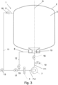
- the 3 shows a third embodiment of a mixing device according to the invention.
- the representation in 1 shows a first exemplary embodiment of a mixing device 1 according to the invention for producing a free-flowing product.
- the mixing device 1 comprises a mixing container 2 which is designed to be liquid-tight and/or gas-tight. At the top area, the mixing container includes a first inlet 5.
- the interior 3 of the mixing container is also equipped with an agitator, which in 1 is not shown to simplify the illustration.
- the agitator can preferably be rotated about an axis of rotation D, which is arranged vertically in the exemplary embodiment.
- the agitator may have one or more blades mounted for rotation about the axis of rotation.
- the agitator can comprise one or more scrapers which are set up to scrape off material adhering to an inner wall of the mixing container 2 during a movement about the axis of rotation.
- the agitator can consist of several independent stirring elements.
- the agitator can be designed as a coaxial agitator, which comprises a scraping agitator and a conveying agitator that is driven independently of the scraping agitator.
- An outlet 15 is provided in the bottom area of the mixing container 2 , via which the product can be drawn off from the mixing container 2 .
- a homogenization device 4 is arranged on the mixing container 2, here inside the mixing container 2, via which the product can be finely homogenized.
- the homogenization device 4 can be a rotor-stator homogenizer, for example.
- the mixing device 1 comprises a conveying device 7 with a suction side 7.1 and a pressure side 7.2, the suction side 7.1 being connected to the outlet 15 of the mixing container 2, in particular to the homogenization device 4, and the pressure side 7.2 being optionally connected to the first inlet 5 of the mixing container 2 is connectable. Also provided between the outlet 15 and the suction side of the conveying device 7 is an adding device 10 for adding an additive, in particular a powdered additive.
- the conveyor device 7 is arranged outside of the mixing container 2 and, as in 1 shown, be integrated into a base section of the mixing device 1.
- the conveying device 7 comprises a drive shaft 9 designed as a hollow shaft, which is arranged concentrically to a drive shaft 8 of the homogenization device 4 . This enables a space-saving arrangement to be made possible.
- the delivery device 7 is preferably designed as a displacement pump.
- An embodiment of the conveying device 7 as a rotary piston pump or membrane pump or sinusoidal pump or eccentric screw pump is particularly preferred, since in this way a particularly gentle, low-shear conveying of the product can be made possible.
- the mixing device 1 also includes a first return line 11 between the pressure side 7.2 of the conveying device 7 and the first inlet 5 of the mixing container 2.
- the product conveyed by the conveying device 7 can be returned to the mixing container via this return line 11. Since the addition of powdery additives takes place on the suction side 7.1 of the conveyor device 7 and the additives can already mix in the return line 11, dust formation when introducing the product into the mixing container 2 can be effectively reduced or prevented.
- a product output 13 is also provided on the pressure side 7.2 of the conveyor device 7 .
- the product outlet 13 is designed as a valve that can be opened selectively in order to withdraw the product from the mixing device 1. Here the product can be conveyed through the conveying device 7 .
- the mixing device 1 also includes a second return line 12 between the pressure side of the conveyor device 7 and a second inlet 6 of the mixing container 1, which is arranged in the region of the homogenization device 4.
- the second return line 12, in cooperation with the second inlet 6, enables small amounts of the product to be circulated.
- the second inlet 6 opens into a channel which runs vertically on the inner wall of the container and which ends in an inlet region of the homogenization device 4 .
- the second inlet 6 is arranged in a lower area of the mixing container 1 , here in a lower third of a filling volume of the mixing container 1 , more precisely in a bottom area of the mixing container 1 .
- the mixing device 1 comprises a switching device, which is formed from two valves 17, 19 connected to the pressure side 7.2 of the conveying device 7.
- the pressure side 7 . 2 of the conveying device 7 can be optionally connected to the first return line 11 or the second return line 12 by the switching device 17 , 19 .
- the mixing container 2 comprises a further addition device 20 in the area of its outlet 5, here in the inlet area of the homogenization device 4.
- a second embodiment of a mixing device 1 according to the invention is shown.
- the mixing device 1 according to the second embodiment essentially corresponds to the mixing device according to the first embodiment, with the difference that in the second embodiment, two separate, non-concentrically arranged drive shafts 8, 9 are provided for driving the homogenization device 4 and the conveyor device 7.
- the drive shaft 8 of the homogenization device 4 can be rotated about a vertical axis of rotation which is parallel to the axis of rotation D of the agitator, which is not shown, and is in particular identical to this axis of rotation D.
- the drive axis 9 of the conveying device 7 is arranged at an angle relative to the drive axis 8 of the homogenization device 4, preferably at an angle in the range from 15 to 45°, for example by 30°.
- a method can be used in which a product contained within the mixing container 2 is homogenized by the homogenization device 4 arranged in the area of the outlet 15 of the mixing container 2, with the conveyor device 7 connected to the outlet 15 of the mixing container 2 discharging the product the outlet 15 sucks, and through an arranged between the outlet 15 of the mixing container 2 and the conveyor device 7 adding device 10, in particular powdered additive is added.
- a pressure in the range from 0.95 bar to 1.05 bar is set in the mixing container 2, in particular normal pressure, for example 1.01 bar. In this respect it is not necessary to generate a negative pressure or a vacuum in the mixing container 2 .
- the mixing tank can be vented to the ambient pressure without differential pressure.
- the product can be mixed with the additive in the mixing container 2 by the agitator of the mixing device 1.
- the conveying device 7 preferably conveys a mixture of the product and the additive through a first return line 11 to the first inlet 5 of the mixing container 2.
- the product can optionally be returned to the mixing container 2 through the second return line 12 .
- the conveyor device 7 conveys the product with the additive to the second inlet 6 of the mixing container 2 in the area of the homogenization device 4.
- the product can be drawn off from the mixing device 1 via the product outlet 13 .
- a bypass not shown in the drawings can be activated, which creates a direct connection between the outlet 15 of the mixing container and the pressure side 7.2 of the conveying device 7.
- the product can then be conveyed solely by the conveying capacity of the homogenization device 4, for example into the first return line 11, the second return line 12 or the product outlet 13.
- a third embodiment of a mixing device 1 according to the invention is shown.
- the mixing device 1 according to the third exemplary embodiment essentially corresponds to the mixing device according to the first exemplary embodiment, with the difference that the homogenization device 4 is arranged on the pressure side of the conveyor device 7 in the third exemplary embodiment.
- the homogenization device is not located in the area of the outlet 15 of the mixing container 2 , but is arranged externally of the mixing container 2 .
- the homogenization device 4 can be a rotor-stator homogenizer, for example.
- the mixing device 1 comprises a mixing container 2 which is designed to be liquid-tight and/or gas-tight.
- the mixing container includes a first inlet 5.
- the interior 3 of the mixing container is also equipped with an agitator, which is not shown to simplify the illustration and can be designed as described in connection with the first exemplary embodiment.
- An outlet 15 is provided in the bottom area of the mixing container 2 , via which the product can be drawn off from the mixing container 2 .
- an adding device 10 for adding an additive, in particular a powdered additive. Furthermore, between the outlet 15 and the addition device 10 arranged flow control device 16 is arranged.
- the conveying device 7 can be arranged outside of the mixing container 2 or in the area of the outlet 5 , for example flanged to the outlet 5 .
- the delivery device 7 is preferably designed as a displacement pump.
- An embodiment of the conveying device 7 as a rotary piston pump or membrane pump or sinusoidal pump or eccentric screw pump is particularly preferred, since in this way a particularly gentle, low-shear conveying of the product can be made possible.
- the mixing device 1 also includes a first return line 11 between the homogenization device 4 and the first inlet 5 of the mixing container 2.
- the product conveyed by the conveyor device 7 can be returned to the mixing container via this return line 11. Since the addition of powdery additives takes place on the suction side 7.1 of the conveyor device 7 and the additives can already mix in the return line 11, dust formation when introducing the product into the mixing container 2 can be effectively reduced or prevented.
- a product output 13 is also provided on the pressure side of the homogenization device 4 .
- the product outlet 13 is designed as a valve that can be opened selectively in order to withdraw the product from the mixing device 1. Here the product can be conveyed through the conveying device 7 .
- the mixing device 1 also includes a second return line 12 between the homogenization device 4 and a second inlet 6 of the mixing container 1, which is in a lower area of the mixing container 1, here in a lower third of a filling volume of the mixing container 1, more precisely in a bottom area of the mixing container 1 , is arranged.
- the second return line 12, in cooperation with the second inlet 6, enables small amounts of the product to be circulated.
- a method can be used in which a product contained within the mixing container 2 is homogenized by the homogenization device 4 arranged outside the mixing container 2, with the conveying device 7 connected to the outlet 15 of the mixing container 2 sucking the product out of the outlet 15 , and by means of an addition device 10 arranged between the outlet 15 of the mixing container 2 and the conveying device 7, an additive, in particular in powder form, is added.
- a pressure in the range from 0.95 bar to 1.05 bar is set in the mixing container 2, in particular normal pressure, for example 1.01 bar. In this respect, it is not necessary to generate a negative pressure or vacuum in the mixing container.
- the product can be mixed with the additive in the mixing container 2 by the agitator of the mixing device 1.
- the mixing device 1 comprises a switching device, which is formed from two valves 17, 19 connected to the homogenization device 4.
- the switching device 17, 19 allows the homogenization device 4 to be connected either to the first return line 11 or to the second return line 12.
- a small amount of product-ingredient mixture can be started in the mixing tank 2, with the second recycle line 12 being used to recycle the product-ingredient mixture.
- the valve 17 of the first return line 11 is switched impermeable and the valve 19 of the second return line 12 is switched permeable. It can then be added through the addition device 10, which is sucked in by the conveyor 7 additive material.
- the product-additive mixture can be returned to the mixing tank 2 via the first return line 11, with the valve 17 of the first return line 11 being permeable and the valve 19 of the second return line 12 being impermeable is switched.
- the product can be drawn off from the mixing device 1 via the product outlet 13 .
Landscapes
- Chemical & Material Sciences (AREA)
- Chemical Kinetics & Catalysis (AREA)
- Dispersion Chemistry (AREA)
- Processing And Handling Of Plastics And Other Materials For Molding In General (AREA)
Applications Claiming Priority (1)
| Application Number | Priority Date | Filing Date | Title |
|---|---|---|---|
| DE102021209275.6A DE102021209275A1 (de) | 2021-08-24 | 2021-08-24 | Mischeinrichtung zur Herstellung eines fließfähigen Produkts und Verfahren zum Betrieb einer Mischeinrichtung |
Publications (4)
| Publication Number | Publication Date |
|---|---|
| EP4140571A2 true EP4140571A2 (fr) | 2023-03-01 |
| EP4140571A3 EP4140571A3 (fr) | 2023-05-03 |
| EP4140571B1 EP4140571B1 (fr) | 2024-09-25 |
| EP4140571C0 EP4140571C0 (fr) | 2024-09-25 |
Family
ID=82399431
Family Applications (1)
| Application Number | Title | Priority Date | Filing Date |
|---|---|---|---|
| EP22183548.1A Active EP4140571B1 (fr) | 2021-08-24 | 2022-07-07 | Mélangeur destiné à la fabrication d'un produit coulant et procédé permettant de faire fonctionner un mélangeur |
Country Status (2)
| Country | Link |
|---|---|
| EP (1) | EP4140571B1 (fr) |
| DE (1) | DE102021209275A1 (fr) |
Citations (1)
| Publication number | Priority date | Publication date | Assignee | Title |
|---|---|---|---|---|
| DE102004040446A1 (de) | 2004-08-20 | 2006-03-09 | A. Berents Gmbh & Co Kg | Vorrichtung und Verfahren zum Mischen eines fließfähigen Produkts und eines insbesondere pulverförmigen Zuschlagstoffes |
Family Cites Families (11)
| Publication number | Priority date | Publication date | Assignee | Title |
|---|---|---|---|---|
| US5564825A (en) * | 1992-12-02 | 1996-10-15 | Shrader Canada Limited | Integral inlet valve and mixer to promote mixing of fluids in a tank |
| DE20000841U1 (de) * | 2000-01-19 | 2000-03-30 | Tuchenhagen GmbH, 21514 Büchen | Düsenvorrichtung in einer Auflöseapparatur zur Auflösung eines Feststoffes in einem Lösungsmittel |
| DE10204921C1 (de) * | 2002-02-07 | 2003-10-16 | Romaco Ag Frymakoruma Rheinfel | Dispergier-Vorrichtung |
| PL2242566T3 (pl) | 2008-01-16 | 2021-05-17 | Tetra Laval Holdings & Finance S.A. | Mieszalnik hybrydowy |
| DE102010005517B4 (de) | 2010-01-23 | 2012-04-19 | Gea Tuchenhagen Gmbh | Dispergierpumpe |
| JP2011036862A (ja) * | 2010-08-05 | 2011-02-24 | Sintokogio Ltd | 循環式分散システム及び循環式分散方法 |
| DE102010042209A1 (de) | 2010-10-08 | 2012-04-12 | Bayer Materialscience Aktiengesellschaft | Herstellung von Kohlenstoffnanoröhren -haltigen Dispersionen |
| US10207204B2 (en) * | 2013-03-01 | 2019-02-19 | Tetra Laval Holdings & Finance S.A. | Liquid processing mixer for mixing a liquid with an additive |
| CN104096507A (zh) * | 2014-07-25 | 2014-10-15 | 苏州世名科技股份有限公司 | 固液混合装置 |
| DE202016000169U1 (de) * | 2016-01-14 | 2017-04-20 | Symex Gmbh & Co. Kg | Pump- und/oder Mischeinrichtung zum Fördern, Homogenisieren und/oder Dispergieren fließfähiger Produkte |
| DE202021104186U1 (de) | 2021-08-05 | 2021-11-16 | Axel Wittek | Bodenelement für eine Anlage mit Rotor-Stator-System |
-
2021
- 2021-08-24 DE DE102021209275.6A patent/DE102021209275A1/de active Pending
-
2022
- 2022-07-07 EP EP22183548.1A patent/EP4140571B1/fr active Active
Patent Citations (1)
| Publication number | Priority date | Publication date | Assignee | Title |
|---|---|---|---|---|
| DE102004040446A1 (de) | 2004-08-20 | 2006-03-09 | A. Berents Gmbh & Co Kg | Vorrichtung und Verfahren zum Mischen eines fließfähigen Produkts und eines insbesondere pulverförmigen Zuschlagstoffes |
Also Published As
| Publication number | Publication date |
|---|---|
| EP4140571B1 (fr) | 2024-09-25 |
| EP4140571A3 (fr) | 2023-05-03 |
| DE102021209275A1 (de) | 2023-03-02 |
| EP4140571C0 (fr) | 2024-09-25 |
Similar Documents
| Publication | Publication Date | Title |
|---|---|---|
| EP1471993B1 (fr) | Dispositif de dispersion | |
| DE69501365T2 (de) | Vorrichtung zum kontinuierlichen Mischen von Flüssigkeit und Pulver | |
| EP2572777B1 (fr) | Moyen de sortie pour disperseur à rotor-stator | |
| EP1475143B1 (fr) | Dispositif pour disperser ou homogénéiser | |
| DE2924317C2 (de) | Zweistufige Strangpreßvorrichtung für thermoplastische Formmassen, insbesondere für pulverförmige Kunststoffe | |
| EP3202489B1 (fr) | Dispositif destiné à homogénéiser et/ou disperser des produits fluides | |
| EP0570335A1 (fr) | Dispositif et procédé pour mélanger un composant pulvérulent solide dans un matériau liquide | |
| AT511564B1 (de) | Mischvorrichtung und verfahren zum mischen eines schüttgutes oder einer pastösen masse | |
| DE19537303B4 (de) | Vorrichtung zum Homogenisieren fließfähiger Stoffe | |
| DE6910964U (de) | Mischvorrichtung | |
| EP1121974B1 (fr) | Dispositif de mélange et l'utilisation | |
| EP1712271B1 (fr) | Dispositif pour homogénéiser et/ou disperser des matériaux fluides | |
| EP0760254B1 (fr) | Dispositif pour l'homogénéisation de matériaux coulants | |
| EP4140571B1 (fr) | Mélangeur destiné à la fabrication d'un produit coulant et procédé permettant de faire fonctionner un mélangeur | |
| EP3334519B1 (fr) | Dispositif et procédé destinés à la dispersion d'au moins une substance dans un fluide | |
| EP1964604A2 (fr) | Procédé et dispositif destinés à la fabrication continue d'un mélange d'au moins deux phases liquides | |
| DE19923378A1 (de) | Vorrichtung zum Homogenisieren fließfähiger Stoffe | |
| CH426735A (de) | Kombinierte Misch- und Homogenisiermaschine | |
| EP0832682A1 (fr) | Appareil d'homogénéisation et dispersion de phases liquides | |
| EP1627676B1 (fr) | Appareil et procédé pour mélanger un produit fluide avec en particulier un additif poudreux | |
| DE102022101814B4 (de) | Vorrichtung, System und Verfahren zum Homogenisieren und/oder Dispergieren fließfähiger Stoffe | |
| EP2676725B1 (fr) | Dispositif et procédé de mélange, notamment de dispersion | |
| EP1155733B1 (fr) | Homogénéisateur pour la production de produits coulables | |
| EP4635615A2 (fr) | Procédé et dispositif pour agir sur un fluide dans un récipient | |
| DE202022104411U1 (de) | Bodenelement für eine Anlage mit Rotor-Stator-System |
Legal Events
| Date | Code | Title | Description |
|---|---|---|---|
| PUAI | Public reference made under article 153(3) epc to a published international application that has entered the european phase |
Free format text: ORIGINAL CODE: 0009012 |
|
| STAA | Information on the status of an ep patent application or granted ep patent |
Free format text: STATUS: THE APPLICATION HAS BEEN PUBLISHED |
|
| AK | Designated contracting states |
Kind code of ref document: A2 Designated state(s): AL AT BE BG CH CY CZ DE DK EE ES FI FR GB GR HR HU IE IS IT LI LT LU LV MC MK MT NL NO PL PT RO RS SE SI SK SM TR |
|
| PUAL | Search report despatched |
Free format text: ORIGINAL CODE: 0009013 |
|
| AK | Designated contracting states |
Kind code of ref document: A3 Designated state(s): AL AT BE BG CH CY CZ DE DK EE ES FI FR GB GR HR HU IE IS IT LI LT LU LV MC MK MT NL NO PL PT RO RS SE SI SK SM TR |
|
| RIC1 | Information provided on ipc code assigned before grant |
Ipc: B01F 25/52 20220101ALI20230324BHEP Ipc: B01F 27/808 20220101ALI20230324BHEP Ipc: B01F 23/50 20220101ALI20230324BHEP Ipc: B01F 23/53 20220101ALI20230324BHEP Ipc: B01F 25/53 20220101AFI20230324BHEP |
|
| STAA | Information on the status of an ep patent application or granted ep patent |
Free format text: STATUS: REQUEST FOR EXAMINATION WAS MADE |
|
| 17P | Request for examination filed |
Effective date: 20231103 |
|
| RBV | Designated contracting states (corrected) |
Designated state(s): AL AT BE BG CH CY CZ DE DK EE ES FI FR GB GR HR HU IE IS IT LI LT LU LV MC MK MT NL NO PL PT RO RS SE SI SK SM TR |
|
| GRAP | Despatch of communication of intention to grant a patent |
Free format text: ORIGINAL CODE: EPIDOSNIGR1 |
|
| STAA | Information on the status of an ep patent application or granted ep patent |
Free format text: STATUS: GRANT OF PATENT IS INTENDED |
|
| INTG | Intention to grant announced |
Effective date: 20240613 |
|
| GRAS | Grant fee paid |
Free format text: ORIGINAL CODE: EPIDOSNIGR3 |
|
| GRAA | (expected) grant |
Free format text: ORIGINAL CODE: 0009210 |
|
| STAA | Information on the status of an ep patent application or granted ep patent |
Free format text: STATUS: THE PATENT HAS BEEN GRANTED |
|
| AK | Designated contracting states |
Kind code of ref document: B1 Designated state(s): AL AT BE BG CH CY CZ DE DK EE ES FI FR GB GR HR HU IE IS IT LI LT LU LV MC MK MT NL NO PL PT RO RS SE SI SK SM TR |
|
| REG | Reference to a national code |
Ref country code: GB Ref legal event code: FG4D Free format text: NOT ENGLISH |
|
| REG | Reference to a national code |
Ref country code: CH Ref legal event code: EP |
|
| REG | Reference to a national code |
Ref country code: DE Ref legal event code: R096 Ref document number: 502022001743 Country of ref document: DE |
|
| REG | Reference to a national code |
Ref country code: IE Ref legal event code: FG4D Free format text: LANGUAGE OF EP DOCUMENT: GERMAN |
|
| U01 | Request for unitary effect filed |
Effective date: 20241024 |
|
| U07 | Unitary effect registered |
Designated state(s): AT BE BG DE DK EE FI FR IT LT LU LV MT NL PT RO SE SI Effective date: 20241106 |
|
| PG25 | Lapsed in a contracting state [announced via postgrant information from national office to epo] |
Ref country code: NO Free format text: LAPSE BECAUSE OF FAILURE TO SUBMIT A TRANSLATION OF THE DESCRIPTION OR TO PAY THE FEE WITHIN THE PRESCRIBED TIME-LIMIT Effective date: 20241225 |
|
| PG25 | Lapsed in a contracting state [announced via postgrant information from national office to epo] |
Ref country code: GR Free format text: LAPSE BECAUSE OF FAILURE TO SUBMIT A TRANSLATION OF THE DESCRIPTION OR TO PAY THE FEE WITHIN THE PRESCRIBED TIME-LIMIT Effective date: 20241226 |
|
| PG25 | Lapsed in a contracting state [announced via postgrant information from national office to epo] |
Ref country code: RS Free format text: LAPSE BECAUSE OF FAILURE TO SUBMIT A TRANSLATION OF THE DESCRIPTION OR TO PAY THE FEE WITHIN THE PRESCRIBED TIME-LIMIT Effective date: 20241225 |
|
| PG25 | Lapsed in a contracting state [announced via postgrant information from national office to epo] |
Ref country code: RS Free format text: LAPSE BECAUSE OF FAILURE TO SUBMIT A TRANSLATION OF THE DESCRIPTION OR TO PAY THE FEE WITHIN THE PRESCRIBED TIME-LIMIT Effective date: 20241225 Ref country code: NO Free format text: LAPSE BECAUSE OF FAILURE TO SUBMIT A TRANSLATION OF THE DESCRIPTION OR TO PAY THE FEE WITHIN THE PRESCRIBED TIME-LIMIT Effective date: 20241225 Ref country code: GR Free format text: LAPSE BECAUSE OF FAILURE TO SUBMIT A TRANSLATION OF THE DESCRIPTION OR TO PAY THE FEE WITHIN THE PRESCRIBED TIME-LIMIT Effective date: 20241226 |
|
| PG25 | Lapsed in a contracting state [announced via postgrant information from national office to epo] |
Ref country code: IS Free format text: LAPSE BECAUSE OF FAILURE TO SUBMIT A TRANSLATION OF THE DESCRIPTION OR TO PAY THE FEE WITHIN THE PRESCRIBED TIME-LIMIT Effective date: 20250125 |
|
| PG25 | Lapsed in a contracting state [announced via postgrant information from national office to epo] |
Ref country code: SM Free format text: LAPSE BECAUSE OF FAILURE TO SUBMIT A TRANSLATION OF THE DESCRIPTION OR TO PAY THE FEE WITHIN THE PRESCRIBED TIME-LIMIT Effective date: 20240925 |
|
| PG25 | Lapsed in a contracting state [announced via postgrant information from national office to epo] |
Ref country code: ES Free format text: LAPSE BECAUSE OF FAILURE TO SUBMIT A TRANSLATION OF THE DESCRIPTION OR TO PAY THE FEE WITHIN THE PRESCRIBED TIME-LIMIT Effective date: 20240925 |
|
| PG25 | Lapsed in a contracting state [announced via postgrant information from national office to epo] |
Ref country code: PL Free format text: LAPSE BECAUSE OF FAILURE TO SUBMIT A TRANSLATION OF THE DESCRIPTION OR TO PAY THE FEE WITHIN THE PRESCRIBED TIME-LIMIT Effective date: 20240925 Ref country code: CZ Free format text: LAPSE BECAUSE OF FAILURE TO SUBMIT A TRANSLATION OF THE DESCRIPTION OR TO PAY THE FEE WITHIN THE PRESCRIBED TIME-LIMIT Effective date: 20240925 |
|
| PG25 | Lapsed in a contracting state [announced via postgrant information from national office to epo] |
Ref country code: SK Free format text: LAPSE BECAUSE OF FAILURE TO SUBMIT A TRANSLATION OF THE DESCRIPTION OR TO PAY THE FEE WITHIN THE PRESCRIBED TIME-LIMIT Effective date: 20240925 |
|
| PLBE | No opposition filed within time limit |
Free format text: ORIGINAL CODE: 0009261 |
|
| STAA | Information on the status of an ep patent application or granted ep patent |
Free format text: STATUS: NO OPPOSITION FILED WITHIN TIME LIMIT |
|
| 26N | No opposition filed |
Effective date: 20250626 |
|
| U20 | Renewal fee for the european patent with unitary effect paid |
Year of fee payment: 4 Effective date: 20250725 |
|
| PG25 | Lapsed in a contracting state [announced via postgrant information from national office to epo] |
Ref country code: HR Free format text: LAPSE BECAUSE OF FAILURE TO SUBMIT A TRANSLATION OF THE DESCRIPTION OR TO PAY THE FEE WITHIN THE PRESCRIBED TIME-LIMIT Effective date: 20240925 |
|
| REG | Reference to a national code |
Ref country code: CH Ref legal event code: H13 Free format text: ST27 STATUS EVENT CODE: U-0-0-H10-H13 (AS PROVIDED BY THE NATIONAL OFFICE) Effective date: 20260224 |
|
| REG | Reference to a national code |
Ref country code: CH Ref legal event code: K11 Free format text: ST27 STATUS EVENT CODE: U-0-0-K10-K11 (AS PROVIDED BY THE NATIONAL OFFICE) Effective date: 20260409 Ref country code: CH Ref legal event code: R17 Free format text: ST27 STATUS EVENT CODE: U-0-0-R10-R17 (AS PROVIDED BY THE NATIONAL OFFICE) Effective date: 20260409 Ref country code: CH Ref legal event code: U11 Free format text: ST27 STATUS EVENT CODE: U-0-0-U10-U11 (AS PROVIDED BY THE NATIONAL OFFICE) Effective date: 20260409 |
|
| PG25 | Lapsed in a contracting state [announced via postgrant information from national office to epo] |
Ref country code: CH Free format text: LAPSE BECAUSE OF NON-PAYMENT OF DUE FEES Effective date: 20250731 |