EP4140573A1 - Appareil de génération d'aérosol - Google Patents
Appareil de génération d'aérosol Download PDFInfo
- Publication number
- EP4140573A1 EP4140573A1 EP21792533.8A EP21792533A EP4140573A1 EP 4140573 A1 EP4140573 A1 EP 4140573A1 EP 21792533 A EP21792533 A EP 21792533A EP 4140573 A1 EP4140573 A1 EP 4140573A1
- Authority
- EP
- European Patent Office
- Prior art keywords
- section
- opening
- aerosol
- generation device
- aerosol generation
- Prior art date
- Legal status (The legal status is an assumption and is not a legal conclusion. Google has not performed a legal analysis and makes no representation as to the accuracy of the status listed.)
- Pending
Links
- 239000000443 aerosol Substances 0.000 title claims abstract description 51
- 238000010438 heat treatment Methods 0.000 claims abstract description 81
- 238000004891 communication Methods 0.000 claims abstract description 23
- 238000003780 insertion Methods 0.000 claims description 10
- 230000037431 insertion Effects 0.000 claims description 10
- 230000008878 coupling Effects 0.000 claims description 8
- 238000010168 coupling process Methods 0.000 claims description 8
- 238000005859 coupling reaction Methods 0.000 claims description 8
- 230000001681 protective effect Effects 0.000 claims description 7
- 239000000758 substrate Substances 0.000 abstract description 70
- 239000007789 gas Substances 0.000 description 53
- 235000019504 cigarettes Nutrition 0.000 description 10
- 238000000889 atomisation Methods 0.000 description 5
- 238000010586 diagram Methods 0.000 description 5
- 239000003517 fume Substances 0.000 description 5
- 238000005266 casting Methods 0.000 description 3
- 238000001746 injection moulding Methods 0.000 description 3
- 230000000694 effects Effects 0.000 description 2
- 230000005611 electricity Effects 0.000 description 2
- 239000007788 liquid Substances 0.000 description 2
- 230000013011 mating Effects 0.000 description 2
- 238000012986 modification Methods 0.000 description 2
- 230000004048 modification Effects 0.000 description 2
- 239000000243 solution Substances 0.000 description 2
- 241000208125 Nicotiana Species 0.000 description 1
- 235000002637 Nicotiana tabacum Nutrition 0.000 description 1
- 230000004308 accommodation Effects 0.000 description 1
- 230000002411 adverse Effects 0.000 description 1
- 230000004075 alteration Effects 0.000 description 1
- 230000009286 beneficial effect Effects 0.000 description 1
- 230000000903 blocking effect Effects 0.000 description 1
- 239000000428 dust Substances 0.000 description 1
- 238000005516 engineering process Methods 0.000 description 1
- 239000004615 ingredient Substances 0.000 description 1
- 238000009413 insulation Methods 0.000 description 1
- 230000007246 mechanism Effects 0.000 description 1
- 230000035515 penetration Effects 0.000 description 1
- 239000000126 substance Substances 0.000 description 1
- 230000008016 vaporization Effects 0.000 description 1
Images



Classifications
-
- B—PERFORMING OPERATIONS; TRANSPORTING
- B01—PHYSICAL OR CHEMICAL PROCESSES OR APPARATUS IN GENERAL
- B01J—CHEMICAL OR PHYSICAL PROCESSES, e.g. CATALYSIS OR COLLOID CHEMISTRY; THEIR RELEVANT APPARATUS
- B01J13/00—Colloid chemistry, e.g. the production of colloidal materials or their solutions, not otherwise provided for; Making microcapsules or microballoons
- B01J13/0095—Preparation of aerosols
-
- A—HUMAN NECESSITIES
- A24—TOBACCO; CIGARS; CIGARETTES; SIMULATED SMOKING DEVICES; SMOKERS' REQUISITES
- A24F—SMOKERS' REQUISITES; MATCH BOXES; SIMULATED SMOKING DEVICES
- A24F40/00—Electrically operated smoking devices; Component parts thereof; Manufacture thereof; Maintenance or testing thereof; Charging means specially adapted therefor
- A24F40/40—Constructional details, e.g. connection of cartridges and battery parts
-
- A—HUMAN NECESSITIES
- A24—TOBACCO; CIGARS; CIGARETTES; SIMULATED SMOKING DEVICES; SMOKERS' REQUISITES
- A24F—SMOKERS' REQUISITES; MATCH BOXES; SIMULATED SMOKING DEVICES
- A24F40/00—Electrically operated smoking devices; Component parts thereof; Manufacture thereof; Maintenance or testing thereof; Charging means specially adapted therefor
- A24F40/40—Constructional details, e.g. connection of cartridges and battery parts
- A24F40/46—Shape or structure of electric heating means
-
- A—HUMAN NECESSITIES
- A24—TOBACCO; CIGARS; CIGARETTES; SIMULATED SMOKING DEVICES; SMOKERS' REQUISITES
- A24F—SMOKERS' REQUISITES; MATCH BOXES; SIMULATED SMOKING DEVICES
- A24F40/00—Electrically operated smoking devices; Component parts thereof; Manufacture thereof; Maintenance or testing thereof; Charging means specially adapted therefor
- A24F40/20—Devices using solid inhalable precursors
Definitions
- the present invention relates to an atomization device, and more particularly to an aerosol generation device.
- An electronic atomization device as an emerging technology, is operated by heating a cigarette liquid or a low-temperature cigarette to replace the traditional burning cigarette so as to have a low operation temperature and harmful substances contained in the fume generated thereby are far less than the traditional burning cigarettes.
- the electronic atomization device can significantly avoid the adverse effects that the cigarettes cast on human bodies and is a healthier way of tabaco inhaling.
- the electronic atomization devices that are currently available in the market are generally classified in two types, one of which is an electronic atomization device that forms an inhalable fume by vaporizing the cigarette liquid, and a second one is an aerosol generation device that forms an inhalable fume by heating a tabaco aerosol-forming substrate in a low-temperature heating but non-combusting way.
- a heater such as a heating plate
- the ingredient components of the aerosol-forming substrate are caused to vaporize to generate fume to be inhaled by people.
- the aerosol-forming substrate When a cigarette has been heated for a predetermined time such that the amount of fume generated thereby reaches an upper limit, the aerosol-forming substrate must be withdrawn from the aerosol generation device, or inhaling must be stopped, or replacement with a fresh aerosol-forming substrate must be made for subsequent inhaling. In this moment, it is a critical issue to easily and efficiently withdraw the aerosol-forming substrate from the aerosol generation device in such a way as to cause no damage to the aerosol-forming substrate and leave no residues on the heater.
- the known aerosol generation devices are often operated by hand pulling to remove the aerosol-forming substrate from the aerosol generation device. Since the forces applied by users may be different and the magnitudes of pulling forces may be significantly different, many users, when pulling the cigarette, often suffers problems of the aerosol-forming substrate being pulled broken or tobacco left on the heater.
- the technical problem to be solved by the present invention is to provide an improved aerosol generation device.
- the technical solution adopted by the present invention to solve the technical problem is to construct an aerosol generation device, including a fixing tube configured to fix an aerosol-forming substrate, a gas passage tube sleeved around the outer circumference of the fixing tube, and a heating assembly;
- the fixing tube includes a fixing section that fixes the aerosol-forming substrate and is removably inserted into the gas passage tube and is in a tubular form;
- the fixing section is of a hollow structure, of which an interior forms an insertion channel; the first opening and the second opening are respectively arranged on two ends of the fixing section and are in communication with the insertion channel.
- a gap is formed between the fixing section and the gas passage tube.
- a through hole is formed in a sidewall of the fixing section and is in communication with the gas passage tube.
- the fixing tube further includes a mounting section arranged at the first opening of the fixing section;
- the top cover and the mounting section are provided with a coupling structure for releasably connecting the top cover to the mounting section.
- the coupling structure includes a locking fastener arranged on a sidewall of the mounting section and a locking slot arranged in the inner side of the top cover and arranged to face the locking fastener.
- a protective lid is further included and is slidably mounted on the top cover to close and block the third opening.
- a slider is arranged in a hollow compartment of the mounting section and is slidable in a direction toward the third opening; an elastic piece is arranged between the slider and the sidewall of the mounting section;
- the heating assembly includes a heating body that inserts through the support wall to insert from the second opening into the aerosol-forming substrate.
- the heating body is in a shape of a columnar configuration.
- the heating body includes a main portion that is cylindrical and a sharp tip structure that is arranged on one end of the main portion and is in a shape of a conical form; the aerosol-forming substrate is withdrawable, through rotation, from the second opening toward the first opening to separate from the heating body.
- the support wall has a through aperture that receives the heating body to penetrate into the fixing tube.
- the cross-sectional shape of the through aperture corresponds to the cross-sectional shape of the heating body, and the cross-sectional size of the through aperture is less than the cross-sectional size of the second opening.
- the heat-generating assembly further includes a retaining frame configured for mounting the heating body; the gas passage tube is sliding-engageable with the retaining frame.
- the retaining frame includes a sleeve body, and the sleeve body includes a first sleeving section, and a second sleeving section that is arranged side by side with respect to the first sleeving section in a transverse direction and is connected to the first sleeving section; the height of the second sleeving section is less than the height of the first sleeving section, and the heating body is extendable out of the second sleeving section.
- the sidewall of the first sleeving section that is adjacent to the second sleeving section is provided with a first joining section
- a sidewall of the gas passage tube is provided with an operation section; the operation section comprises multiple elongate recesses.
- the aerosol generation device further includes a power supply assembly connected with the heating assembly.
- the aerosol generation device when put into use, allows the aerosol-forming substrate to extend from the first opening of the fixing tube into the fixing tube, and then, the heating assembly inserts through a support arm of the gas passage tube to insert from the second opening into the aerosol-forming substrate in order to implement heating to the aerosol-forming substrate. After the heating is completed, the aerosol-forming substrate is withdrawn from the fixing tube toward the first opening, and the heating assembly and the aerosol-forming substrate are separated.
- the aerosol generation device allows for efficient removal of the aerosol-forming substrate from the fixing tube without causing damages thereto and prevents a medium of the aerosol-forming substrate from residually remaining in the aerosol generation device.
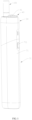
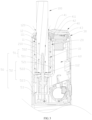
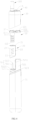
- FIGS. 1 and 2 show embodiments of an aerosol generation device according to the present invention.
- the aerosol generation device is operable to heat an aerosol-forming base-body 100 in a low-temperature heating but non-combusting manner, and in some embodiments, the aerosol-forming substrate 100 can be a cigarette.
- the aerosol generation device includes an accommodating assembly, a gas passage tube 20, a gas flow channel, and a heating assembly 50.
- the accommodating assembly includes a fixing tube 10 and a top cover 30.
- the fixing tube 10 is arranged in the top cover 30 to be releasably connected to the top cover 30, and is connected by means of an arrangement of connection assembly to the top cover 30 to form a one-piece structure.
- the fixing tube 10 can be integrally formed with the top cover 30, such as the top cover 30 being integrally formed by means of injection molding or casting.
- the fixing tube 10 is configured to hold and fix the aerosol-forming substrate 100.
- the gas passage tube 20 is arranged in the top cover 30 and is sleeved around the outer circumference of the fixing tube 10 to form a gas flow channel for gas to flow therethrough.
- the top cover 30 is releasably fit over outside of the gas passage tube 20 and the heating assembly 50.
- the gas flow channel is in communication with the outside, and the gas flow channel allows external gas to get into the aerosol-forming substrate 100 in the fixing tube 10.
- the heating assembly 50 is releasably connected to the fixing tube 10, and the heating assembly 50 is insertable into the aerosol-forming substrate 100 in the fixing tube 10 and is operable to heat up the aerosol-forming substrate 100.
- the fixing tube 10 is a hollow and two-end-penetrating structure and functions for receiving the aerosol-forming substrate 100 to insert therein. Further, in some embodiments, the fixing tube 10 includes a fixing section 11 and a mounting section 12. The fixing section 11 is configured to hold and fix the aerosol-forming substrate 100, and the mounting section 12 is arranged at one end of the fixing section 11 to be mating with and mounted to the top cover 30.
- the fixing section 11 is in a shape of a tubular form, which is a hollow and two-end-penetrating structure having an interior forming an insertion channel, and specifically, the fixing section 11 is in the form of a round tube and the insertion channel is of a cylindrical configuration that is configured to receive the aerosol-forming substrate 100 to insert therein.
- the two ends of the fixing tube 10 are respectively provided with a first opening 111 and a second opening 112; specifically, in some embodiments, the first opening 111 and the second opening 112 are respectively arranged at the two ends of the fixing section 11 and are in an arrangement of being symmetrical along an axial direction and in communication with the insertion channel.
- the aerosol-forming substrate 100 can be inserted through the first opening 111 into the fixing tube and is withdrawable from the fixing tube 112 toward the first opening 111, and specifically, the aerosol-forming substrate 100 can be inserted to reach the second opening 112, and can be withdrawn from the second opening 112 toward the first opening 111.
- the aerosol-forming substrate 100 has a length that is greater than the distance between the first opening 111 and the second opening 112, and the aerosol-forming substrate 100 may extend beyond the second opening to abut against a support wall of the gas passage tube 20. In some other embodiments, the aerosol-forming substrate 100 may not reach the second opening.
- the first opening 111 is made a horn and a radial dimension of the first opening 111 is arranged to be gradually reduced in a direction toward the second opening 112 in order to facilitate insertion of the aerosol-forming substrate 100 therein.
- a sidewall of the fixing section 11 is formed with through holes 113, and there may be multiple ones of such through holes 113, and specifically, in some embodiments, the multiple through holes 113 are divided into three groups and the three groups of the through holes 113 are arranged side by side in an axial direction of the fixing section 11.
- Each group of the through holes 113 comprises three through holes 113 arranged at intervals in a circumferential direction of the fixing section 11, and each of the through holes 113 is an elongate opening.
- the through holes 113 are not limited to be plural ones and there can be just one or simply omitted. Opening such through holes 113 helps reduce a contact area between the aerosol-forming substrate 100 and the fixing tube 10 so as to reduce an amount of heat transfer of the aerosol-forming substrate 100.
- the mounting section 12 is arranged in the fixing section 11 at a location facingthe first opening 111 and has a cross section that is elliptical.
- the cross section has a shape and size to face the shape and size of a cross section of an interior of the top cover 30.
- the mounting section 12 comprises a hollow compartment 121 and a sidewall 122.
- the hollow compartment 121 has a top side that is provided with an opening and the opening is in communication with a third opening 31 formed in the top cover 30.
- the hollow compartment 121 is arranged to be in communication with the insertion channel of the fixing section 11.
- the sidewall 122 is arranged around the outer circumference of the hollow compartment 121 and is connected to a tubular wall of the fixing section 11 and is integrally formed with the fixing section 11, and specifically, in some embodiments, is integrally formed with the fixing section 11 by means of casting or injection molding.
- a bottom wall of the mounting section 12 and the sidewall of the fixing section 11 are provided with inlet openings 13.
- the inlet openings 13 are not limited to be two and are not limited to be arranged in the bottom wall of the mounting section 12 or the sidewall of the fixing section 11.
- the hollow compartment 121 is in communication with the inlet opening 13 to form a first inlet channel 120.
- the gas passage tube 20 is sleeved around the outer circumference of the fixing section 11 so as to form a gap with respect to the fixing section 11.
- the inlet openings 13 are in communication with the gap, and the gap realizes, on one hand, an effect of thermal insulation during heating and, on the other hand, accommodation of a residue of the aerosol-forming substrate 100 after heating, where to clear out the residue, the top cover 30 is slid off and the fixing tube 10 is removed out of the gas passage tube 20, and the residue in the gas passage tube 20 can be simply poured out.
- the height of the gas passage tube 20 is greater than or equal to the height of the fixing section 11.
- the gas passage tube 20 comprises a tubular body 21, and the tubular body 21 is sleeved around the outer circumference of the fixing section 11.
- the interior of the tubular body 21 is in a shape of a cylindrical form.
- the radial dimension of the gas passage tube 20 is greater than the radial dimension of the fixing section 11.
- the gas passage tube 20 and the fixing section 11 define therebetween the gap, so as to form a second inlet channel 210 in communication with the first inlet channel 120.
- one end of the gas passage tube 20 is formed with a support wall 211.
- the support wall 211 is arranged at an end of the tubular body 21, and is arranged to face the second opening 112 for functioning to support the aerosol-forming substrate 100.
- the support wall 211 is further formed with a through aperture 2111.
- the cross-sectional shape of the through aperture 2111 corresponds to the cross-sectional shape of a heating body 51 of the heating assembly 50, and in some embodiments, the through aperture 2111 is circular for receiving heating assembly 50 to penetrate into the fixing tube 10 to ease penetration of the heating body 51 of the heating assembly 50 into the aerosol-forming substrate 100.
- the cross-sectional size of the through aperture 2111 is smaller than the cross-sectional size of the second opening 112, in order to prevent the aerosol-forming substrate 100 from projecting out of the gas passage tube 20.
- the support wall 211 is provided with two support platforms 212.
- the two support platforms 212 are arranged in an interior of the tubular body 21, and the two support platforms 212 are respectively located on two opposite sides of the through aperture 2111. An interval between the two support platforms 212 forms a third inlet channel 213 that is in communication with the second inlet channel 210.
- the third inlet channel 213 is arranged to face the second opening 112 and is in communication with the second opening 112, so as to allow gas to enter and get into the aerosol-forming substrate 100 in the fixing tube 10.
- the support platforms 212 are not limited, in number, to be two and can be of multiple ones.
- the gas passage tube 20 further comprises a first engagement section 22 that is arranged on one side of the tubular body 21 and projecting outward and a second engagement section 23 that is arranged on one end of the tubular body 21 and in a projecting configuration.
- the first engagement section 22 and the second engagement section 23 are both slidably combinable with the heating assembly 50 so as to achieve releasable connection of the entirety of the gas passage tube 20 with the heating assembly 50.
- a sidewall of the gas passage tube 20 is provided with an operation section 24, and the operation section 24 may comprise multiple recesses in a strip form to define a finger position on which a user's finger is positionable to increase a fictional force between the user's finger and the gas passage tube 20 to allow the user to easily perform an operation of mounting and removing the gas passage tube 20.
- the top cover 30 is removably sleeved around the outer circumference of the gas passage tube 20.
- the top cover 30 is formed with the third opening 31.
- the third opening 31 can be arranged in a top surface of the top cover 30 and in communication with the hollow compartment 121, and facingthe first opening 111.
- the aerosol-forming substrate 100 can extend, through the third opening 31, into an interior of the first opening 111 to further reach into the second opening 112.
- An inside wall of the third opening 31 can be formed with an inlet cavity 311.
- the inlet cavity 311 can be multiple in number arranged at intervals in a circumferential direction of the third opening 31 and in communication with the first inlet channel 120 to allow external gas to move into the first inlet channel 120.
- the top cover 30 and the mounting section 12 are provided with a coupling structure.
- the coupling structure is configured to releasably connect the top cover 30 and the mounting section 12.
- the coupling structure comprises a locking fastener 1221 and a locking slot 32.
- the locking fastener 1221 is arranged on a sidewall 122 of the mounting section 12 and can be multiple in number, and specifically, in some embodiments, there are four such snap fasteners 1221, and the four snap fasteners 1221 are arranged at intervals in a circumferential direction of the sidewall 122.
- the locking slot 32 is arranged in the inner side of the top cover 30 at a location adjacent to a top wall of the top cover 30, and can be multiple in number arranged facingt he snap fasteners 1221 and snap-connectable the snap fasteners 1221.
- the top cover 30 is fit along the mounting section 12 to sleeve around the outer circumference of the gas passage tube 20, and the snap fasteners 1221 of the mounting section 12 are set, one by one, in snap connection into the locking slots 32.
- the coupling structure when the top cover 10 is slid, the fixing tube 10 is simultaneously withdrawn out of the gas passage tube 20.
- the gas flow channel comprises the first inlet channel 120, the second inlet channel 210, and the third inlet channel 213.
- the first inlet channel 120 is arranged in the accommodating assembly and is located in the top cover 30 and in communication with the outside. Specifically, the first inlet channel 120 is formed of the inlet cavity 311 of the third opening 31, the hollow compartment 121 in the interior of the mounting section 12, and the inlet opening 13 of the fixing section 11.
- the second inlet channel 210 is arranged between the gas passage tube 20 and the fixing tube 10, and is in communication with the first inlet channel 120 and the fixing tube 10, and specifically, the second inlet channel 210 is arranged between the tubular body 21 and the fixing section 11 and is formed of the gap between the tubular body 21 and the fixing section 11, and is in communication with the second opening 112 and the inlet opening 13 to allow the gas flow to get into the aerosol-forming substrate 100 in the fixing tube 10.
- the third inlet channel 213 is formed between the two support platforms 212 of the gas passage tube 20, and is in communication with the second opening 112.
- the second inlet channel 210 By arranging the second inlet channel 210 between the gas passage tube 20 and the fixing tube 10, on the one hand, heat of the heating assembly 50 is prevented from transmitting to the sidewall of the top cover 10 so as to avoid discomfort of hand holding by the user resulting from an excessively high temperature of the sidewall of the top cover 10, and on the other hand, the structure of the gas flow channel is simplified to shorten a gas flow conveyance path to avoid phenomena of jamming or blocking.
- the aerosol generation device further comprises a protective lid 40.
- the protective lid 40 is slidably mounted on the top cover 30, and is movable, through sliding, to close and block the third opening 31 to prevent dust from falling into the fixing tube 10 when there is no aerosol-forming substrate 100 inserted into the fixing tube 10.
- the protective lid 40 comprises a lid body 41, and the lid body 41 is arranged on a top wall of the top cover 30 and is reciprocally slidable in a direction toward the third opening 31.
- the lid body 41 is provided with a connection peg 411, and the connection peg 411 is insertable into the top cover 30.
- the top cover 30 has a guide hole 312, and the guide hole 312 is arranged to be in communication with the third opening 31.
- the guide hole 312 can be an elongate opening in a strip form.
- the connection peg 411 is insertable through the guide hole 312 into the top cover 30.
- a slider 42 is arranged in the hollow compartment 121 of the mounting section 12, and the slider 42 is arranged to be slidable in a direction toward the third opening 31.
- the connection peg 411 is connected with the slider 42 to drive the slider 42 to slide.
- An elastic piece 43 is arranged between the slider 42 and the sidewall of the mounting section 12. The elastic piece 43 generates a spring force to ease sliding and returning of the slider 42.
- the heating assembly 50 comprises the heating body 51.
- the heating body 51 inserts through the support wall 211 to insert through the second opening 112 into the aerosol-forming substrate 100.
- the heating body 51 extends through the through aperture 2111.
- the heating body 51 is in a shape of a columnar configuration, and certainly, in some other embodiments, the heating body 51 is not limited to a columnar configuration and can be in the form of a plate.
- the heating body 51 comprises a cylindrical main portion 511 and a sharp tip structure 512. The sharp tip structure 512 is arranged at one end of the main portion 511 to ease the insertion of the heating body 51 into the aerosol-forming substrate 100.
- the sharp tip structure 512 is in a shape of a conical form.
- the aerosol-forming substrate 100 is withdrawable from the second opening 112 toward the first opening 111 by means of rotation to be separated from the heating body 51 to thereby ease removal and replacement of the aerosol-forming substrate 100.
- the heat-generating assembly further comprises a retaining frame 52.
- the retaining frame 52 functions for mounting the heating body 51 and is combinable with the gas passage tube 20 through sliding engagement, and may receive the top cover 30 to sleeve therearound.
- the retaining frame 52 is in the form of a sleeve body, and the sleeve body comprises a first sleeving section 521 and a second sleeving section 522.
- the first sleeving section 521 and the second sleeving section 522 are arranged side by side in a transverse direction and are integrally formed, and specifically, in some embodiments, the first sleeving section 521 and the second sleeving section 522 are integrally formed together by means of injection molding or casting.
- An interior of the first sleeving section 521 receives a control circuit board 60 therein.
- the control circuit board 60 is connected to the heating assembly 50 and is operable to activate or deactivate the heating assembly 50.
- the sidewall of the first sleeving section 521 that is adjacent to the second sleeving section 522 is provided with a first joining section 5211.
- the first joining section 5211 can be a joining projection arranged on the first sleeving section 521 and is combinable with and fixed to the first engagement section 22 arranged on one side of the tubular body 21, and specifically, a first slide channel is formed inside the first engagement section 22, and the first slide channel is connectable with the joining projection through sliding.
- the height of the second sleeving section 522 is less than the height of the first sleeving section 521, and the heating body 51 is extendable out of the second sleeving section 522.
- the gas passage tube 20 is arranged on the top of the second sleeving section 522.
- the second sleeving section 522 is provided with a second joining section 5221, and the second joining section 5221 can be a joining projection, and the joining projection is connectable with the second engagement section 23 arranged at one end of the tubular body 21, and specifically, a second slide channel is formed inside the second engagement section 23, and the second slide channel is connectable with the joining projection through sliding.
- the first engagement section 22 of the gas passage tube 20 is fit onto the first joining section 5211, and the second engagement section 23 is sleeved around the second joining section 5221 and sliding is made in a longitudinal direction of the first joining section 5211 and the second joining section 5221 to have the support wall of the tubular body of the gas passage tube 20 abutting the bottom wall of the second joining section 5221.
- the retaining frame 52 further comprises a rim 523 mating the top cover 30. The rim 523 abuts an outer circumferential wall of the first sleeving section 521 and the second sleeving section 522.
- the heating assembly 50 further comprises a bracket 53 mounted in cooperation with the retaining frame 52, and the retaining frame 52 is fit to the bracket 53.
- the heating body 51 is arranged on the bracket 53.
- the aerosol generation device further comprises a power supply assembly 70.
- the power supply assembly 70 is mechanically and electrically connected to the heating assembly 50 to supply electricity to the heating assembly 50.
- the power supply assembly 70 comprises a power casing 71 and a battery 72 arranged in the power casing 71.
- the retaining frame 52 is arranged in the open end of the power casing 71.
- the power casing 71 is provided thereon with an activation-deactivation switch 711, and the activation-deactivation switch 711 is in connection with the control circuit board 60.
- the battery 72 is connected with the heating assembly 50 and supplies electricity to the heating assembly 50. Specifically, in some embodiments, the battery 72 is connected by means of the control circuit board 60 to the heating assembly 50.
- the aerosol-forming substrate 100 is inserted through the third opening 31 to penetrate from the first opening 111 into the interior of the second opening 112, or the aerosol-forming substrate 100 is inserted through the third opening 31 to penetrate from the first opening 111 into the interior of the fixing tube 10 and to project out of the second opening 112 to abut against the support wall 211, and meanwhile, the heating body 51 of the heating assembly 50 is caused to penetrate through the support wall 211 to insert from the second opening 112 into the interior of the aerosol-forming substrate 100, so as to carry out heating toward the aerosol-forming substrate 100.
- the aerosol-forming substrate 100 is rotated to have the aerosol-forming substrate 100 to withdraw from the second opening 112 toward the first opening 111 to thereby separate from the heating body 51 of the heating assembly 50.
- a cigarette push mechanism may be provided to push, from the second opening 112, the aerosol-forming substrate 100 out.
Landscapes
- Chemical & Material Sciences (AREA)
- Organic Chemistry (AREA)
- Dispersion Chemistry (AREA)
- Chemical Kinetics & Catalysis (AREA)
- Containers And Packaging Bodies Having A Special Means To Remove Contents (AREA)
- Disinfection, Sterilisation Or Deodorisation Of Air (AREA)
- Sampling And Sample Adjustment (AREA)
Applications Claiming Priority (2)
| Application Number | Priority Date | Filing Date | Title |
|---|---|---|---|
| CN202010318151.7A CN111420621B (zh) | 2020-04-21 | 2020-04-21 | 气溶胶产生装置 |
| PCT/CN2021/077278 WO2021212991A1 (fr) | 2020-04-21 | 2021-02-22 | Appareil de génération d'aérosol |
Publications (2)
| Publication Number | Publication Date |
|---|---|
| EP4140573A1 true EP4140573A1 (fr) | 2023-03-01 |
| EP4140573A4 EP4140573A4 (fr) | 2024-05-29 |
Family
ID=71556538
Family Applications (1)
| Application Number | Title | Priority Date | Filing Date |
|---|---|---|---|
| EP21792533.8A Pending EP4140573A4 (fr) | 2020-04-21 | 2021-02-22 | Appareil de génération d'aérosol |
Country Status (5)
| Country | Link |
|---|---|
| EP (1) | EP4140573A4 (fr) |
| JP (1) | JP7447309B2 (fr) |
| KR (1) | KR102863793B1 (fr) |
| CN (1) | CN111420621B (fr) |
| WO (1) | WO2021212991A1 (fr) |
Cited By (1)
| Publication number | Priority date | Publication date | Assignee | Title |
|---|---|---|---|---|
| EP4602950A1 (fr) * | 2024-02-15 | 2025-08-20 | Imperial Tobacco Limited | Appareil de génération d'aérosol |
Families Citing this family (11)
| Publication number | Priority date | Publication date | Assignee | Title |
|---|---|---|---|---|
| CN111420621B (zh) * | 2020-04-21 | 2025-06-17 | 深圳麦时科技有限公司 | 气溶胶产生装置 |
| CN111420620B (zh) * | 2020-04-21 | 2025-06-17 | 深圳麦时科技有限公司 | 气溶胶产生装置 |
| CN111972712B (zh) * | 2020-07-07 | 2024-08-27 | 深圳麦时科技有限公司 | 气溶胶产生装置 |
| CN111904031B (zh) * | 2020-07-24 | 2024-08-27 | 深圳麦时科技有限公司 | 气溶胶产生装置 |
| CN112656044B (zh) * | 2020-12-25 | 2024-08-09 | 深圳麦时科技有限公司 | 气溶胶产生装置及其提取器组件 |
| CN113508926B (zh) * | 2021-06-24 | 2024-08-20 | 深圳麦时科技有限公司 | 气溶胶产生装置 |
| CN114831342A (zh) * | 2022-01-25 | 2022-08-02 | 深圳麦时科技有限公司 | 气溶胶形成系统、装置及制品的插取导向固定结构 |
| CN114886157A (zh) * | 2022-04-25 | 2022-08-12 | 深圳麦时科技有限公司 | 气溶胶形成装置及其防护盖结构 |
| CN115088877A (zh) * | 2022-06-15 | 2022-09-23 | 深圳麦时科技有限公司 | 气溶胶产生装置及气溶胶形成基体组件 |
| CN115736367A (zh) * | 2022-11-17 | 2023-03-07 | 思摩尔国际控股有限公司 | 气溶胶产生装置及发热组件 |
| CN119198456B (zh) * | 2024-09-20 | 2025-09-05 | 山东科技大学 | 一种用于模拟粉尘环境自适应作业的智能控制发尘装置 |
Family Cites Families (17)
| Publication number | Priority date | Publication date | Assignee | Title |
|---|---|---|---|---|
| KR20190046804A (ko) * | 2016-09-15 | 2019-05-07 | 필립모리스 프로덕츠 에스.에이. | 전자 에어로졸 발생 흡연 장치 |
| KR20180070457A (ko) * | 2016-12-16 | 2018-06-26 | 주식회사 케이티앤지 | 에어로졸 생성 장치 |
| RU2749137C2 (ru) * | 2016-12-16 | 2021-06-04 | Кей Ти Энд Джи Корпорейшн | Устройство и способ генерирования аэрозоля |
| US11197497B2 (en) | 2017-04-11 | 2021-12-14 | Kt&G Corporation | Aerosol generating device |
| CN207653596U (zh) * | 2017-11-22 | 2018-07-27 | 惠州市吉瑞科技有限公司深圳分公司 | 一种雾化组件以及电子烟 |
| CN108185537B (zh) * | 2018-02-26 | 2020-11-20 | 冷朝阳 | 一种气溶胶生成装置及气溶胶生成制品 |
| CN208581844U (zh) * | 2018-07-05 | 2019-03-08 | 深圳市艾维普思科技有限公司 | 加热装置及电子烟 |
| CN109007986B (zh) * | 2018-09-29 | 2024-11-29 | 深圳市古可生物科技有限公司 | 电子烟 |
| CN209152360U (zh) * | 2018-09-29 | 2019-07-26 | 深圳市丽福科技有限责任公司 | 电子烟具 |
| EP3636084B1 (fr) * | 2018-10-12 | 2021-12-01 | JT International S.A. | Dispositif de génération d'aérosols et chambre de chauffage correspondant |
| CN110771956B (zh) | 2019-11-26 | 2020-12-08 | 深圳市吉迩科技有限公司 | 电子烟 |
| CN110946330B (zh) | 2019-12-23 | 2024-08-09 | 深圳麦时科技有限公司 | 一种电子雾化装置及其提取器 |
| CN111387566B (zh) * | 2020-03-25 | 2024-08-02 | 深圳麦时科技有限公司 | 加热装置及气溶胶形成装置 |
| CN111420621B (zh) * | 2020-04-21 | 2025-06-17 | 深圳麦时科技有限公司 | 气溶胶产生装置 |
| CN212524042U (zh) * | 2020-04-21 | 2021-02-12 | 深圳麦时科技有限公司 | 气溶胶产生装置 |
| CN111420620B (zh) * | 2020-04-21 | 2025-06-17 | 深圳麦时科技有限公司 | 气溶胶产生装置 |
| CN212345294U (zh) * | 2020-07-07 | 2021-01-15 | 深圳麦时科技有限公司 | 气溶胶产生装置 |
-
2020
- 2020-04-21 CN CN202010318151.7A patent/CN111420621B/zh active Active
-
2021
- 2021-02-22 JP JP2022562806A patent/JP7447309B2/ja active Active
- 2021-02-22 WO PCT/CN2021/077278 patent/WO2021212991A1/fr not_active Ceased
- 2021-02-22 KR KR1020227036883A patent/KR102863793B1/ko active Active
- 2021-02-22 EP EP21792533.8A patent/EP4140573A4/fr active Pending
Cited By (2)
| Publication number | Priority date | Publication date | Assignee | Title |
|---|---|---|---|---|
| EP4602950A1 (fr) * | 2024-02-15 | 2025-08-20 | Imperial Tobacco Limited | Appareil de génération d'aérosol |
| WO2025172410A1 (fr) * | 2024-02-15 | 2025-08-21 | Imperial Tobacco Limited | Appareil de génération d'aérosol |
Also Published As
| Publication number | Publication date |
|---|---|
| EP4140573A4 (fr) | 2024-05-29 |
| JP2023522200A (ja) | 2023-05-29 |
| KR20230002476A (ko) | 2023-01-05 |
| KR102863793B1 (ko) | 2025-09-24 |
| WO2021212991A1 (fr) | 2021-10-28 |
| CN111420621B (zh) | 2025-06-17 |
| CN111420621A (zh) | 2020-07-17 |
| JP7447309B2 (ja) | 2024-03-11 |
Similar Documents
| Publication | Publication Date | Title |
|---|---|---|
| EP4140574A1 (fr) | Dispositif de génération d'aérosol | |
| KR102863793B1 (ko) | 에어러졸 발생장치 | |
| KR102761817B1 (ko) | 에어로졸 발생 시스템 | |
| EP4179901A1 (fr) | Dispositif de génération d'aérosol | |
| DK3145341T3 (en) | INDUCTIVE HEATER AND AEROSOL GENERATION SYSTEM | |
| WO2019178834A1 (fr) | Dispositif à fumée sans combustion ayant un extracteur | |
| CN108497559A (zh) | 一种气雾产生装置 | |
| CN216701662U (zh) | 气雾生成装置 | |
| BR112020002032B1 (pt) | Sistema gerador de aerossol eletricamente operável, dispositivo gerador de aerossol e método para recarregar um dispositivo gerador de aerossol | |
| CN212524042U (zh) | 气溶胶产生装置 | |
| CN216147260U (zh) | 气雾生成装置 | |
| JP7182704B2 (ja) | 排出器を含むエアロゾル生成装置 | |
| KR20190089272A (ko) | 순간 가열이 가능한 궐련형 전자담배 기기 | |
| JP7465352B2 (ja) | 移動可能な部分を備えたエアロゾル発生装置 | |
| CN212464888U (zh) | 气溶胶生成系统和电源装置 | |
| JP2024531467A (ja) | 格納可能なマウスピースおよび滅菌放射線源を有するエアロゾル発生装置 | |
| KR20190089276A (ko) | 궐련형 전자담배 기기 | |
| CN212468057U (zh) | 气溶胶产生装置 | |
| CN110959915A (zh) | 气雾产生装置及推动机构 | |
| CN211882187U (zh) | 气雾产生装置及推动机构 | |
| CN222776962U (zh) | 一种防保护罩脱落丢失的电子烟 | |
| US20250120442A1 (en) | Aerosol generating system and aerosol generating device | |
| US20240251880A1 (en) | Aerosol-generating system and aerosol-generating device | |
| RU2780738C2 (ru) | Генерирующая аэрозоль система |
Legal Events
| Date | Code | Title | Description |
|---|---|---|---|
| STAA | Information on the status of an ep patent application or granted ep patent |
Free format text: STATUS: THE INTERNATIONAL PUBLICATION HAS BEEN MADE |
|
| PUAI | Public reference made under article 153(3) epc to a published international application that has entered the european phase |
Free format text: ORIGINAL CODE: 0009012 |
|
| STAA | Information on the status of an ep patent application or granted ep patent |
Free format text: STATUS: REQUEST FOR EXAMINATION WAS MADE |
|
| 17P | Request for examination filed |
Effective date: 20221110 |
|
| AK | Designated contracting states |
Kind code of ref document: A1 Designated state(s): AL AT BE BG CH CY CZ DE DK EE ES FI FR GB GR HR HU IE IS IT LI LT LU LV MC MK MT NL NO PL PT RO RS SE SI SK SM TR |
|
| DAV | Request for validation of the european patent (deleted) | ||
| DAX | Request for extension of the european patent (deleted) | ||
| REG | Reference to a national code |
Ref country code: DE Ref legal event code: R079 Free format text: PREVIOUS MAIN CLASS: B01J0013000000 Ipc: A24F0040400000 |
|
| A4 | Supplementary search report drawn up and despatched |
Effective date: 20240426 |
|
| RIC1 | Information provided on ipc code assigned before grant |
Ipc: A24F 40/20 20200101ALN20240422BHEP Ipc: A24F 40/46 20200101ALI20240422BHEP Ipc: B01J 13/00 20060101ALI20240422BHEP Ipc: A24F 40/40 20200101AFI20240422BHEP |