EP4140621A1 - Dispositif de fusion laser sélectif de type à commutation rapide à double poudre - Google Patents
Dispositif de fusion laser sélectif de type à commutation rapide à double poudre Download PDFInfo
- Publication number
- EP4140621A1 EP4140621A1 EP20946403.1A EP20946403A EP4140621A1 EP 4140621 A1 EP4140621 A1 EP 4140621A1 EP 20946403 A EP20946403 A EP 20946403A EP 4140621 A1 EP4140621 A1 EP 4140621A1
- Authority
- EP
- European Patent Office
- Prior art keywords
- powder
- suction port
- building
- cylinder
- laser melting
- Prior art date
- Legal status (The legal status is an assumption and is not a legal conclusion. Google has not performed a legal analysis and makes no representation as to the accuracy of the status listed.)
- Withdrawn
Links
Images

Classifications
-
- B—PERFORMING OPERATIONS; TRANSPORTING
- B33—ADDITIVE MANUFACTURING TECHNOLOGY
- B33Y—ADDITIVE MANUFACTURING, i.e. MANUFACTURING OF THREE-DIMENSIONAL [3D] OBJECTS BY ADDITIVE DEPOSITION, ADDITIVE AGGLOMERATION OR ADDITIVE LAYERING, e.g. BY 3D PRINTING, STEREOLITHOGRAPHY OR SELECTIVE LASER SINTERING
- B33Y30/00—Apparatus for additive manufacturing; Details thereof or accessories therefor
-
- B—PERFORMING OPERATIONS; TRANSPORTING
- B22—CASTING; POWDER METALLURGY
- B22F—WORKING METALLIC POWDER; MANUFACTURE OF ARTICLES FROM METALLIC POWDER; MAKING METALLIC POWDER; APPARATUS OR DEVICES SPECIALLY ADAPTED FOR METALLIC POWDER
- B22F10/00—Additive manufacturing of workpieces or articles from metallic powder
- B22F10/20—Direct sintering or melting
- B22F10/28—Powder bed fusion, e.g. selective laser melting [SLM] or electron beam melting [EBM]
-
- B—PERFORMING OPERATIONS; TRANSPORTING
- B22—CASTING; POWDER METALLURGY
- B22F—WORKING METALLIC POWDER; MANUFACTURE OF ARTICLES FROM METALLIC POWDER; MAKING METALLIC POWDER; APPARATUS OR DEVICES SPECIALLY ADAPTED FOR METALLIC POWDER
- B22F10/00—Additive manufacturing of workpieces or articles from metallic powder
- B22F10/30—Process control
- B22F10/32—Process control of the atmosphere, e.g. composition or pressure in a building chamber
- B22F10/322—Process control of the atmosphere, e.g. composition or pressure in a building chamber of the gas flow, e.g. rate or direction
-
- B—PERFORMING OPERATIONS; TRANSPORTING
- B22—CASTING; POWDER METALLURGY
- B22F—WORKING METALLIC POWDER; MANUFACTURE OF ARTICLES FROM METALLIC POWDER; MAKING METALLIC POWDER; APPARATUS OR DEVICES SPECIALLY ADAPTED FOR METALLIC POWDER
- B22F10/00—Additive manufacturing of workpieces or articles from metallic powder
- B22F10/30—Process control
- B22F10/34—Process control of powder characteristics, e.g. density, oxidation or flowability
-
- B—PERFORMING OPERATIONS; TRANSPORTING
- B22—CASTING; POWDER METALLURGY
- B22F—WORKING METALLIC POWDER; MANUFACTURE OF ARTICLES FROM METALLIC POWDER; MAKING METALLIC POWDER; APPARATUS OR DEVICES SPECIALLY ADAPTED FOR METALLIC POWDER
- B22F10/00—Additive manufacturing of workpieces or articles from metallic powder
- B22F10/70—Recycling
- B22F10/73—Recycling of powder
-
- B—PERFORMING OPERATIONS; TRANSPORTING
- B22—CASTING; POWDER METALLURGY
- B22F—WORKING METALLIC POWDER; MANUFACTURE OF ARTICLES FROM METALLIC POWDER; MAKING METALLIC POWDER; APPARATUS OR DEVICES SPECIALLY ADAPTED FOR METALLIC POWDER
- B22F12/00—Apparatus or devices specially adapted for additive manufacturing; Auxiliary means for additive manufacturing; Combinations of additive manufacturing apparatus or devices with other processing apparatus or devices
- B22F12/70—Gas flow means
-
- B—PERFORMING OPERATIONS; TRANSPORTING
- B22—CASTING; POWDER METALLURGY
- B22F—WORKING METALLIC POWDER; MANUFACTURE OF ARTICLES FROM METALLIC POWDER; MAKING METALLIC POWDER; APPARATUS OR DEVICES SPECIALLY ADAPTED FOR METALLIC POWDER
- B22F12/00—Apparatus or devices specially adapted for additive manufacturing; Auxiliary means for additive manufacturing; Combinations of additive manufacturing apparatus or devices with other processing apparatus or devices
- B22F12/90—Means for process control, e.g. cameras or sensors
-
- B—PERFORMING OPERATIONS; TRANSPORTING
- B29—WORKING OF PLASTICS; WORKING OF SUBSTANCES IN A PLASTIC STATE IN GENERAL
- B29C—SHAPING OR JOINING OF PLASTICS; SHAPING OF MATERIAL IN A PLASTIC STATE, NOT OTHERWISE PROVIDED FOR; AFTER-TREATMENT OF THE SHAPED PRODUCTS, e.g. REPAIRING
- B29C64/00—Additive manufacturing, i.e. manufacturing of three-dimensional [3D] objects by additive deposition, additive agglomeration or additive layering, e.g. by 3D printing, stereolithography or selective laser sintering
- B29C64/30—Auxiliary operations or equipment
- B29C64/35—Cleaning
-
- B—PERFORMING OPERATIONS; TRANSPORTING
- B29—WORKING OF PLASTICS; WORKING OF SUBSTANCES IN A PLASTIC STATE IN GENERAL
- B29C—SHAPING OR JOINING OF PLASTICS; SHAPING OF MATERIAL IN A PLASTIC STATE, NOT OTHERWISE PROVIDED FOR; AFTER-TREATMENT OF THE SHAPED PRODUCTS, e.g. REPAIRING
- B29C64/00—Additive manufacturing, i.e. manufacturing of three-dimensional [3D] objects by additive deposition, additive agglomeration or additive layering, e.g. by 3D printing, stereolithography or selective laser sintering
- B29C64/30—Auxiliary operations or equipment
- B29C64/357—Recycling
-
- B—PERFORMING OPERATIONS; TRANSPORTING
- B29—WORKING OF PLASTICS; WORKING OF SUBSTANCES IN A PLASTIC STATE IN GENERAL
- B29C—SHAPING OR JOINING OF PLASTICS; SHAPING OF MATERIAL IN A PLASTIC STATE, NOT OTHERWISE PROVIDED FOR; AFTER-TREATMENT OF THE SHAPED PRODUCTS, e.g. REPAIRING
- B29C64/00—Additive manufacturing, i.e. manufacturing of three-dimensional [3D] objects by additive deposition, additive agglomeration or additive layering, e.g. by 3D printing, stereolithography or selective laser sintering
- B29C64/30—Auxiliary operations or equipment
- B29C64/364—Conditioning of environment
-
- B—PERFORMING OPERATIONS; TRANSPORTING
- B33—ADDITIVE MANUFACTURING TECHNOLOGY
- B33Y—ADDITIVE MANUFACTURING, i.e. MANUFACTURING OF THREE-DIMENSIONAL [3D] OBJECTS BY ADDITIVE DEPOSITION, ADDITIVE AGGLOMERATION OR ADDITIVE LAYERING, e.g. BY 3D PRINTING, STEREOLITHOGRAPHY OR SELECTIVE LASER SINTERING
- B33Y40/00—Auxiliary operations or equipment, e.g. for material handling
-
- B—PERFORMING OPERATIONS; TRANSPORTING
- B33—ADDITIVE MANUFACTURING TECHNOLOGY
- B33Y—ADDITIVE MANUFACTURING, i.e. MANUFACTURING OF THREE-DIMENSIONAL [3D] OBJECTS BY ADDITIVE DEPOSITION, ADDITIVE AGGLOMERATION OR ADDITIVE LAYERING, e.g. BY 3D PRINTING, STEREOLITHOGRAPHY OR SELECTIVE LASER SINTERING
- B33Y50/00—Data acquisition or data processing for additive manufacturing
- B33Y50/02—Data acquisition or data processing for additive manufacturing for controlling or regulating additive manufacturing processes
-
- B—PERFORMING OPERATIONS; TRANSPORTING
- B04—CENTRIFUGAL APPARATUS OR MACHINES FOR CARRYING-OUT PHYSICAL OR CHEMICAL PROCESSES
- B04C—APPARATUS USING FREE VORTEX FLOW, e.g. CYCLONES
- B04C5/00—Apparatus in which the axial direction of the vortex is reversed
- B04C5/14—Construction of the underflow ducting; Apex constructions; Discharge arrangements ; discharge through sidewall provided with a few slits or perforations
- B04C5/185—Dust collectors
-
- B—PERFORMING OPERATIONS; TRANSPORTING
- B22—CASTING; POWDER METALLURGY
- B22F—WORKING METALLIC POWDER; MANUFACTURE OF ARTICLES FROM METALLIC POWDER; MAKING METALLIC POWDER; APPARATUS OR DEVICES SPECIALLY ADAPTED FOR METALLIC POWDER
- B22F12/00—Apparatus or devices specially adapted for additive manufacturing; Auxiliary means for additive manufacturing; Combinations of additive manufacturing apparatus or devices with other processing apparatus or devices
- B22F12/50—Means for feeding of material, e.g. heads
-
- B—PERFORMING OPERATIONS; TRANSPORTING
- B22—CASTING; POWDER METALLURGY
- B22F—WORKING METALLIC POWDER; MANUFACTURE OF ARTICLES FROM METALLIC POWDER; MAKING METALLIC POWDER; APPARATUS OR DEVICES SPECIALLY ADAPTED FOR METALLIC POWDER
- B22F12/00—Apparatus or devices specially adapted for additive manufacturing; Auxiliary means for additive manufacturing; Combinations of additive manufacturing apparatus or devices with other processing apparatus or devices
- B22F12/60—Planarisation devices; Compression devices
-
- Y—GENERAL TAGGING OF NEW TECHNOLOGICAL DEVELOPMENTS; GENERAL TAGGING OF CROSS-SECTIONAL TECHNOLOGIES SPANNING OVER SEVERAL SECTIONS OF THE IPC; TECHNICAL SUBJECTS COVERED BY FORMER USPC CROSS-REFERENCE ART COLLECTIONS [XRACs] AND DIGESTS
- Y02—TECHNOLOGIES OR APPLICATIONS FOR MITIGATION OR ADAPTATION AGAINST CLIMATE CHANGE
- Y02P—CLIMATE CHANGE MITIGATION TECHNOLOGIES IN THE PRODUCTION OR PROCESSING OF GOODS
- Y02P10/00—Technologies related to metal processing
- Y02P10/25—Process efficiency
Definitions
- the present disclosure belongs to the technical field of rapid prototyping, and in particular, to a double-powder rapid switching type selective laser melting apparatus.
- a selective laser melting (SLM for short) apparatus scans selected areas on a new powder layer step by step with fine laser focused spots to form a plane profile, and then stacks layers for forming and manufacturing, thus directly obtain a metal functional part of almost any shape and with complete metallurgical bond and a density of nearly 100%.
- the SLM apparatus simplifies a complex three-dimensional geometry into two-dimensional plane for manufacturing, wherein the manufacturing cost does not depend on the complexity of the part, but on the volume and building orientation of the part.
- the SLM apparatus mainly has the following advantages: 1 Thanks to use of a layered manufacturing technology, formed parts are not affected by geometric complexity, any complex formed metal part is directly manufactured, and especially for personalized and small-batch complex metal products, manufacturing is very convenient. 2 A good beam mode, small laser spots, and high building accuracy are provided via a high power-density fiber laser generator. 3 End metal products are directly obtained through manufacturing. Due to the relatively high laser energy density, a metal material with a high melting point and that is difficult to process is directly processed into end metal products. 4 Formed metal parts are metallurgically formed objects with a relative density of nearly 100% and performance superior to that of conventional castings.
- the present disclosure provides a double-powder rapid switching type selective laser melting apparatus, to reduce the printing cost and improve working efficiency.
- a double-powder rapid switching type selective laser melting apparatus includes a building system, an optical system, a powder recovery system, a gas circulation system, and a control system, wherein the building system, the optical system, the powder recovery system, and the gas circulation system are all controlled by the control system;
- the top powder suction port is disposed along a vertical direction of the building chamber, a cyclone dust collector and a filtering tank are sequentially disposed between the top powder suction port and the first air inlet of the variable frequency fan, and a filter element is provided inside the filtering tank.
- the bottom powder suction port is disposed along a horizontal direction of the building chamber, a cyclone dust collector and a filtering tank are sequentially disposed between the bottom powder suction port and the second air inlet of the variable frequency fan, and a filter element is provided inside the filtering tank.
- the powder suction port uses a corrugated hose suction head.
- the top powder suction port and the bottom powder suction port do not work simultaneously.
- the two openings of the air suction port are both in communication with the third air inlet of the variable frequency fan via a pipe.
- a filtering tank is disposed between the air suction port and the third air inlet of the variable frequency fan, and a filter element is provided inside the filtering tank.
- the beneficial effects of the present disclosure are as follows.
- the present disclosure conveniently and quickly switches to another metal powder for printing, after printing with one metal powder is completed; during printing, both filtration of smoke and dust generated and recovery of powder occur completely independently for two metal powders, to avoid contamination of different metal powders; the present disclosure meets requirements of most small and medium-sized enterprises for multi-material rapid switching type selective laser melting apparatuses, and not only reduces costs, but also greatly improves working efficiency.
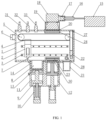
- a double-powder rapid switching type selective laser melting apparatus provided in the embodiments of the present disclosure includes a building system, an optical system, a powder recovery system, a gas circulation system, and a control system.
- the building system includes the building chamber 1, the powder spreading device 2, the powder cylinder 11, and the building cylinder 12.
- the building chamber 1 is completely sealed.
- the two parallel linear guide rails 3 are disposed on a side surface inside the building chamber 1.
- the powder spreading device 2 is slidably connected to the linear guide rails 3.
- the rubber scraper bar 7 used for leveling the powder is mounted on the powder spreading device 2.
- a top end of the powder spreading device 2 is fixed to the synchronous belt 4.
- the synchronous belt 4 and the synchronous pulley 5 mesh, the synchronous pulley 5 is driven by the servo motor 6.
- the synchronous pulley 5 is fixed inside the building chamber 1.
- the servo motor 6 is fixed outside the building chamber 1.
- the linear guide rails 3 are used to precisely guide the powder spreading device 2 and drive the rubber scraper bar 7 to move horizontally with high precision, to ensure uniform powder thickness in a building area (the bottom of the building chamber 1).
- the control system controls a rotation speed of the servo motor 6, and a speed of a powder spreading return stroke is set to be three times a powder spreading speed, to reduce printing time.
- the powder cylinder 11 is fixed to a bottom of the building chamber 1, and the powder cylinder 11 is in communication with the building chamber 1.
- the high-precision electric cylinder 10 is fixed at a bottom of the powder cylinder 11, and the removable movable cylinder body 8 is mounted at an upper end inside the powder cylinder 11.
- a guide rod of the high-precision electric cylinder 10 extends into a lower end inside the powder cylinder 11 and is connected to a bottom of the piston component 9.
- Lubricating oil is applied to the lower end of the powder cylinder 11 where the piston component 9 moves, to reduce the running resistance of the piston.
- a mounting plate and a seal plate are sequentially fixed at a top of the piston component 9. The mounting plate and the seal plate are located inside the movable cylinder body 8.
- the mounting plate When moving to the top end, the mounting plate fits with a bottom end of the building chamber 1.
- a felt ring component 13 is circumferentially fixed on the mounting plate.
- the felt ring component 13 is used to prevent powder from falling through a gap between the mounting plate and the movable cylinder body 8.
- metal powder is fed inside the movable cylinder body 8 of the powder cylinder 11.
- the high-precision electric cylinder 10 is driven by the servo motor B, to control the position of the piston component 9 in the powder cylinder 11.
- a double-layer O ring is circumferentially mounted on a tail end of the piston component 9, to effectively improve the air tightness inside the powder cylinder 11.
- the building cylinder 12 and the powder cylinder 11 have the completely same structures and dimensions.
- the building platform 30 is mounted at a top of the seal plate, and the building platform 30 has a building diameter of 100 mm and a building height of 70 mm.
- the powder spreading ratio of the powder cylinder 11 to the building cylinder 12 during printing is 2:1.
- the rotation speed of the servo motor B is controlled by the control system to drive the high-precision electric cylinder 10, so that an ascending stroke of the powder cylinder 11 is twice a descending stroke of the building cylinder 12.
- the optical system includes the laser generator 15, the beam expander 17, the galvanometer 18, and the field lens 19.
- Laser emitted by the laser incident head 16 of the laser generator 15 is subjected to beam expansion by the beam expander 17, reflected by the galvanometer 18, and then focused by the field lens 19 to form a 30 ⁇ m beam spot in a focal plane.
- the focused laser is directed onto the building platform 30 through the optical protection lens 20 disposed at a top end of the building chamber 1, to melt and form level metal powder spread on a surface of the building platform 30 into the desired shape layer by layer.
- the laser generator 15 is connected to the control system.
- the laser generator 15 adopts an optical fiber generator with a wavelength of 1064 ⁇ m. Quartz glass is used as the material of the optical protection lens 20.
- the powder recovery system includes the powder recovery box 21 and powder suction ports.
- the powder recovery box 21 is mounted at the bottom of the building chamber 1, and is used to collect excess metal powder during powder spreading.
- the powder suction ports are disposed inside the building chamber 1, and there are two powder suction ports in total, namely, the top powder suction port 27 and the bottom powder suction port 28.
- the top powder suction port 27 is disposed along a vertical direction of the building chamber 1, while the bottom powder suction port 28 is disposed along a horizontal direction of the building chamber 1.
- the top powder suction port 27 and the bottom powder suction port 28 are respectively used to recover two different metal powders, to avoid contamination of different metal powders.
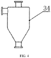
- the top powder suction port 27 is sequentially in communication with the cyclone dust collector 34 ( FIG.
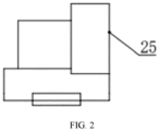
- the filtering tank 26 and a first air inlet of the variable frequency fan 25 ( FIG. 2 ).
- a filter element is provided inside the filtering tank.
- the bottom powder suction port 28 is sequentially in communication with the cyclone dust collector 34, the filtering tank 26, and a second air inlet of the variable frequency fan 25.
- a filter element is provided inside the filtering tank.
- the cyclone dust collector 34 is used to separate powder in a gas mixture.
- the filtering tank 26 is used to filter finer impurities.
- a solenoid valve is further provided on a connecting pipe, and on/off of the solenoid valve is controlled by the control system.
- the powder suction port uses the corrugated hose suction head 22.
- the gas circulation system is used to filter smoke and dust generated during laser melting of metal powder, to prevent the smoke and dust from blocking laser and contaminating the powder.
- the gas circulation system includes the variable frequency fan 25, the filtering tank 26, the air suction port 23, the air blow port 24, and the filter element 29.
- the air blow port 24 is disposed at a top of the building chamber 1.
- the air blow port 24 is in communication with an air outlet of the variable frequency fan 25 via a pipe.
- a solenoid valve is provided on the connecting pipe. On/off of the solenoid valve is controlled by the control system.
- the air blow port 24 blows away smoke and dust on a surface of the optical protection lens 20, to improve printing quality.
- the air suction port 23 is disposed on one side of the building platform 30.
- the air suction port 23 is provided with two openings which are used to suck smoke and dust generated on a surface of the building platform 30 during printing with two different metal powders.
- the two openings are both in communication with a third air inlet of the variable frequency fan 25 via a pipe.
- a solenoid valve is provided on the connecting pipe, and on/off of the solenoid valve is controlled by the control system.
- the filtering tank 26 is provided between the air suction port 23 and the third air inlet of the variable frequency fan 25.
- the filter element 29 is provided inside the filtering tank 26 ( FIG. 3 ). Smoke and dust during printing enter the filtering tank 26 via the air suction port 23 under the action of suction force of the variable frequency fan 25. Gas filtered by the filter element 29 returns into the building chamber 1 via the air blow port 24 for recycling.
- the oxygen content sensor 31, the pressure sensor 32, and the temperature sensor 33 are provided at the top of the building chamber 1 to detect, in real time, oxygen content, pressure, and temperature of gas inside the building chamber 1, and transmit the oxygen content, pressure, and temperature of gas inside the building chamber 1 to the control system.
- the control system When the oxygen content exceeds 1%, the control system outputs a signal to replace gas in the building chamber 1 and reduce oxygen content (the prior art), so as to ensure that parts are not oxidized in the printing process.
- a working process of a double-powder rapid switching type selective laser melting apparatus of the present disclosure is described as below.
- the high-precision electric cylinder 10 at the bottom of the powder cylinder 11 pushes the piston component 9 to move upward, so that the seal plate at the top of the piston component 9 pushes metal powder in the movable cylinder body 8 to the bottom of the building chamber 1.
- the servo motor 6 drives the synchronous pulley 5, so that the synchronous belt 4 moves and drives the rubber scraper bar 7 on the powder spreading device 2 to spread the metal powder at the bottom of the building chamber 1 onto the surface of the building platform 30 located at the top end of the building cylinder 12 (the building platform 30 is flush with the bottom of the building chamber 1 under driving by the high-precision electric cylinder 10).
- the laser incident head 16 of the laser generator 15 emits laser which sequentially goes through the beam expander 17, the galvanometer 18, the field lens 19, and the optical protection lens 20, and is finally directed onto the level metal powder spread on the surface of the building platform 30 for melting and forming, to complete processing and forming of one layer of metal powder.
- the foregoing process is repeated to carry out processing and forming of a second layer of metal powder, until manufacturing of a part is completed.
- Excess metal powder in the processing and forming process is brought by the rubber scraper bar 7 into the powder recovery box 21.
- the smoke and dust generated in the processing and forming process of the metal powder enter the filtering tank 26 via one opening of the air suction port 23 under the action of suction force of the variable frequency fan 25.
- Gas filtered by the filter element 29 returns into the building chamber 1 via the air blow port 24 and blows away smoke and dust on the surface of the optical protection lens 20.
- the control system controls one of the powder suction ports to open and suck all powder at corners of the building chamber under the action of the variable frequency fan 25.
- a part is manufactured according to the same process.
- the smoke and dust generated in the processing and forming process enter the filtering tank 26 via the other opening of the air suction port 23 under the action of suction force of the variable frequency fan 25.
- Gas filtered by the filter element 29 returns into the building chamber 1 via the air blow port 24 and blows away the smoke and dust on the surface of the optical protection lens 20. Powder at the corners of the building chamber is sucked by the other powder suction port.
- the double-powder rapid switching type selective laser melting apparatus provided in the present disclosure is properly designed so that it is convenient and efficient to change the powder, saving time and labor, reducing costs, and greatly improving working efficiency.
- the present disclosure meets requirements of most small and medium-sized enterprises for multi-material rapid switching type selective laser melting apparatuses.
Landscapes
- Engineering & Computer Science (AREA)
- Chemical & Material Sciences (AREA)
- Manufacturing & Machinery (AREA)
- Materials Engineering (AREA)
- Physics & Mathematics (AREA)
- Automation & Control Theory (AREA)
- Mechanical Engineering (AREA)
- Optics & Photonics (AREA)
- Life Sciences & Earth Sciences (AREA)
- Sustainable Development (AREA)
- Analytical Chemistry (AREA)
- Plasma & Fusion (AREA)
- Health & Medical Sciences (AREA)
- Environmental & Geological Engineering (AREA)
- Toxicology (AREA)
- Laser Beam Processing (AREA)
- Powder Metallurgy (AREA)
Applications Claiming Priority (2)
| Application Number | Priority Date | Filing Date | Title |
|---|---|---|---|
| CN202010704662.2A CN111745161A (zh) | 2020-07-21 | 2020-07-21 | 一种双粉快速切换型选择性激光熔融设备 |
| PCT/CN2020/114824 WO2022016689A1 (fr) | 2020-07-21 | 2020-09-11 | Dispositif de fusion laser sélectif de type à commutation rapide à double poudre |
Publications (2)
| Publication Number | Publication Date |
|---|---|
| EP4140621A1 true EP4140621A1 (fr) | 2023-03-01 |
| EP4140621A4 EP4140621A4 (fr) | 2023-10-11 |
Family
ID=72710819
Family Applications (1)
| Application Number | Title | Priority Date | Filing Date |
|---|---|---|---|
| EP20946403.1A Withdrawn EP4140621A4 (fr) | 2020-07-21 | 2020-09-11 | Dispositif de fusion laser sélectif de type à commutation rapide à double poudre |
Country Status (5)
| Country | Link |
|---|---|
| US (1) | US20230241687A1 (fr) |
| EP (1) | EP4140621A4 (fr) |
| JP (1) | JP7352998B2 (fr) |
| CN (1) | CN111745161A (fr) |
| WO (1) | WO2022016689A1 (fr) |
Cited By (1)
| Publication number | Priority date | Publication date | Assignee | Title |
|---|---|---|---|---|
| EP4316700A4 (fr) * | 2021-03-30 | 2025-06-11 | Guangdong Hanbang 3D Tech Co., Ltd. | Dispositif d'impression 3d métal et procédé d'impression 3d métal |
Families Citing this family (6)
| Publication number | Priority date | Publication date | Assignee | Title |
|---|---|---|---|---|
| CN112776124B (zh) * | 2020-12-30 | 2024-07-09 | 东莞理工学院 | 成型仓可快速更换式多材料高固含量陶瓷打印机 |
| CN112756631A (zh) * | 2020-12-31 | 2021-05-07 | 苏州倍丰激光科技有限公司 | 一种金属3d设备的手持式可移动构建仓 |
| CN113232296A (zh) * | 2021-03-31 | 2021-08-10 | 上海工程技术大学 | 一种用于激光增材制造的铺粉装置及铺粉方法 |
| CN114559059B (zh) * | 2022-03-10 | 2023-09-12 | 西安赛隆金属材料有限责任公司 | 粉床电子束增材制造设备及方法 |
| CN114570951B (zh) * | 2022-03-21 | 2023-06-16 | 南京铖联激光科技有限公司 | 一种3d打印机用均匀铺粉装置 |
| CN115647392B (zh) * | 2022-09-08 | 2025-07-11 | 南京铖联激光科技有限公司 | 一种用于3d打印设备的成型仓 |
Family Cites Families (24)
| Publication number | Priority date | Publication date | Assignee | Title |
|---|---|---|---|---|
| DE19853947C1 (de) * | 1998-11-23 | 2000-02-24 | Fraunhofer Ges Forschung | Prozeßkammer für das selektive Laser-Schmelzen |
| US20060214335A1 (en) * | 2005-03-09 | 2006-09-28 | 3D Systems, Inc. | Laser sintering powder recycle system |
| DE102006014694B3 (de) * | 2006-03-28 | 2007-10-31 | Eos Gmbh Electro Optical Systems | Prozesskammer und Verfahren für die Bearbeitung eines Werkstoffs mit einem gerichteten Strahl elektromagnetischer Strahlung, insbesondere für eine Lasersintervorrichtung |
| CN103707366A (zh) * | 2013-12-06 | 2014-04-09 | 简厚诚 | 用于家具生产的裁料机 |
| CN107428080A (zh) * | 2015-03-12 | 2017-12-01 | 株式会社尼康 | 三维造型物制造装置及构造物的制造方法 |
| CN105039970B (zh) * | 2015-07-02 | 2017-10-20 | 西安交通大学 | 一种可更换粉缸双光束激光选区熔化成形设备 |
| CN107921659A (zh) * | 2015-07-23 | 2018-04-17 | 瑞尼斯豪公司 | 增材制造设备和用于此类设备的气体流动装置 |
| DE102015222689A1 (de) * | 2015-11-17 | 2017-05-18 | Realizer Gmbh | Formherstellungsvorrichtung zur Herstellung von Formkörpern durch ortsselektives Verfestigen von Werkstoffpulver |
| CN105345002A (zh) * | 2015-12-08 | 2016-02-24 | 中国工程物理研究院机械制造工艺研究所 | 一种可微量供料的激光增材制造装备的床身结构 |
| CN205183785U (zh) * | 2015-12-08 | 2016-04-27 | 中国工程物理研究院机械制造工艺研究所 | 一种可微量供料的激光增材制造装备的床身结构 |
| JP2018009204A (ja) * | 2016-07-12 | 2018-01-18 | セイコーエプソン株式会社 | 三次元造形装置 |
| CN106041081B (zh) * | 2016-07-25 | 2019-03-29 | 南京前知智能科技有限公司 | 一种牙科专用的选择性融化slm设备 |
| CN205816810U (zh) * | 2016-07-25 | 2016-12-21 | 南京前知智能科技有限公司 | 一种牙科专用的选择性融化slm设备 |
| CN107812940B (zh) * | 2016-09-13 | 2024-05-14 | 苏州中瑞智创三维科技股份有限公司 | 具有双缸结构的金属3d打印机 |
| CN106735220A (zh) * | 2017-01-17 | 2017-05-31 | 华南理工大学 | 一种多材料激光选区熔化成型装置与方法 |
| CN107470621B (zh) * | 2017-08-24 | 2019-04-19 | 北京星航机电装备有限公司 | 一种适于自动化生产线3d打印成形模块化系统及其使用方法 |
| EP3492243A1 (fr) * | 2017-11-29 | 2019-06-05 | CL Schutzrechtsverwaltungs GmbH | Appareil de fabrication additive d'objets tridimensionnels |
| KR101954019B1 (ko) * | 2018-05-21 | 2019-06-17 | 노승모 | Sls 방식 3d 프린터의 조형챔버 교체구조 |
| CN109967737A (zh) * | 2018-12-26 | 2019-07-05 | 西安铂力特增材技术股份有限公司 | 一种用于3d打印设备光学元件保护镜片的自动清洁装置 |
| CN109663919B (zh) * | 2019-02-28 | 2023-08-15 | 韶关学院 | 一种多材料零件3d打印机及其打印方法 |
| KR102090674B1 (ko) * | 2019-07-25 | 2020-03-18 | (주)대건테크 | 잔여분말제거장치를 구비한 3d프린터 |
| CN110722158B (zh) * | 2019-09-16 | 2021-12-07 | 上海航天精密机械研究所 | 一种增强镁合金激光选区熔化蒸气烟尘排出效果的装置 |
| CN110976871B (zh) * | 2019-12-27 | 2025-02-07 | 湖南华曙高科技股份有限公司 | 选择性激光烧结设备的粉末回收循环系统及其控制方法 |
| CN212761117U (zh) * | 2020-07-21 | 2021-03-23 | 南京前知智能科技有限公司 | 一种双粉快速切换型选择性激光熔融设备 |
-
2020
- 2020-07-21 CN CN202010704662.2A patent/CN111745161A/zh active Pending
- 2020-09-11 JP JP2022579762A patent/JP7352998B2/ja active Active
- 2020-09-11 US US18/011,845 patent/US20230241687A1/en not_active Abandoned
- 2020-09-11 EP EP20946403.1A patent/EP4140621A4/fr not_active Withdrawn
- 2020-09-11 WO PCT/CN2020/114824 patent/WO2022016689A1/fr not_active Ceased
Cited By (1)
| Publication number | Priority date | Publication date | Assignee | Title |
|---|---|---|---|---|
| EP4316700A4 (fr) * | 2021-03-30 | 2025-06-11 | Guangdong Hanbang 3D Tech Co., Ltd. | Dispositif d'impression 3d métal et procédé d'impression 3d métal |
Also Published As
| Publication number | Publication date |
|---|---|
| EP4140621A4 (fr) | 2023-10-11 |
| JP2023531974A (ja) | 2023-07-26 |
| WO2022016689A1 (fr) | 2022-01-27 |
| JP7352998B2 (ja) | 2023-09-29 |
| US20230241687A1 (en) | 2023-08-03 |
| CN111745161A (zh) | 2020-10-09 |
Similar Documents
| Publication | Publication Date | Title |
|---|---|---|
| EP4140621A1 (fr) | Dispositif de fusion laser sélectif de type à commutation rapide à double poudre | |
| US12397350B2 (en) | Multi-metal material build device using laser 3D printing, and working method thereof | |
| CN112296360B (zh) | 一种增减材制造用局部气体密封装置 | |
| CN113333784B (zh) | 风场自适应调节的增材制造设备及其风场控制方法 | |
| CN106735197B (zh) | 用于制造三维物体的设备及其移动式除烟装置 | |
| US20250091291A1 (en) | Integrated device of bi-directional ultrasonic rolling, powder spreading, and compaction for additive manufacturing | |
| CN207391549U (zh) | 一种激光熔覆机床及其熔覆的轮胎模具 | |
| CN212761117U (zh) | 一种双粉快速切换型选择性激光熔融设备 | |
| CN117862536A (zh) | 一种多金属材料的增材制造成型系统及其使用方法 | |
| CN114393304A (zh) | 一种针对铝合金制品的可多定点焊接装置 | |
| CN112974853B (zh) | 一种直接成型金属聚合物复合材料的3d打印设备及方法 | |
| CN111774738B (zh) | 一种汽车内饰件切割方法 | |
| CN212634317U (zh) | 一种节约金属粉末的slm装置 | |
| CN219881316U (zh) | 一种选区激光熔化设备的高效双向铺粉打印装置 | |
| CN214977758U (zh) | 激光成形技术的型板设备 | |
| CN214602646U (zh) | 一种多功能的激光切割机床身 | |
| CN208374520U (zh) | 一种爬坡交换工作台 | |
| CN213469575U (zh) | 一种提高选区激光熔化成形零件质量的智能除渣装置 | |
| CN214558318U (zh) | 一种大幅面数控激光钢板切割机床 | |
| CN211438104U (zh) | 一种金属铺粉3d打印机 | |
| CN213997794U (zh) | 一种slm设备及其快换式变径成型装置 | |
| CN115889819A (zh) | 一种多工位多材料增材制造成型装置及方法 | |
| CN212495762U (zh) | 一种五金条生产用的裁断机构 | |
| CN220361990U (zh) | 制备多组元连续梯度材料的选区激光熔化3d打印设备 | |
| CN113996810A (zh) | 激光选区熔化slm成形、后处理一体化装置及加工方法 |
Legal Events
| Date | Code | Title | Description |
|---|---|---|---|
| STAA | Information on the status of an ep patent application or granted ep patent |
Free format text: STATUS: THE INTERNATIONAL PUBLICATION HAS BEEN MADE |
|
| PUAI | Public reference made under article 153(3) epc to a published international application that has entered the european phase |
Free format text: ORIGINAL CODE: 0009012 |
|
| STAA | Information on the status of an ep patent application or granted ep patent |
Free format text: STATUS: REQUEST FOR EXAMINATION WAS MADE |
|
| 17P | Request for examination filed |
Effective date: 20221123 |
|
| AK | Designated contracting states |
Kind code of ref document: A1 Designated state(s): AL AT BE BG CH CY CZ DE DK EE ES FI FR GB GR HR HU IE IS IT LI LT LU LV MC MK MT NL NO PL PT RO RS SE SI SK SM TR |
|
| A4 | Supplementary search report drawn up and despatched |
Effective date: 20230912 |
|
| RIC1 | Information provided on ipc code assigned before grant |
Ipc: B22F 12/70 20210101ALI20230906BHEP Ipc: B22F 10/73 20210101ALI20230906BHEP Ipc: B22F 10/34 20210101ALI20230906BHEP Ipc: B22F 10/322 20210101ALI20230906BHEP Ipc: B04C 5/185 20060101ALI20230906BHEP Ipc: B22F 10/28 20210101ALI20230906BHEP Ipc: B29C 64/364 20170101ALI20230906BHEP Ipc: B29C 64/357 20170101ALI20230906BHEP Ipc: B29C 64/35 20170101ALI20230906BHEP Ipc: B33Y 30/00 20150101ALI20230906BHEP Ipc: B22F 3/105 20060101AFI20230906BHEP |
|
| DAV | Request for validation of the european patent (deleted) | ||
| DAX | Request for extension of the european patent (deleted) | ||
| STAA | Information on the status of an ep patent application or granted ep patent |
Free format text: STATUS: THE APPLICATION IS DEEMED TO BE WITHDRAWN |
|
| 18D | Application deemed to be withdrawn |
Effective date: 20240410 |