EP4140647A1 - Structure profilée pour un composant d'une machine-outil et machine-outil dotée d'une structure profilée - Google Patents
Structure profilée pour un composant d'une machine-outil et machine-outil dotée d'une structure profilée Download PDFInfo
- Publication number
- EP4140647A1 EP4140647A1 EP21192816.3A EP21192816A EP4140647A1 EP 4140647 A1 EP4140647 A1 EP 4140647A1 EP 21192816 A EP21192816 A EP 21192816A EP 4140647 A1 EP4140647 A1 EP 4140647A1
- Authority
- EP
- European Patent Office
- Prior art keywords
- profile structure
- machine tool
- component
- cutting arm
- beads
- Prior art date
- Legal status (The legal status is an assumption and is not a legal conclusion. Google has not performed a legal analysis and makes no representation as to the accuracy of the status listed.)
- Withdrawn
Links
Images



Classifications
-
- B—PERFORMING OPERATIONS; TRANSPORTING
- B24—GRINDING; POLISHING
- B24B—MACHINES, DEVICES, OR PROCESSES FOR GRINDING OR POLISHING; DRESSING OR CONDITIONING OF ABRADING SURFACES; FEEDING OF GRINDING, POLISHING, OR LAPPING AGENTS
- B24B41/00—Component parts such as frames, beds, carriages, headstocks
-
- B—PERFORMING OPERATIONS; TRANSPORTING
- B24—GRINDING; POLISHING
- B24B—MACHINES, DEVICES, OR PROCESSES FOR GRINDING OR POLISHING; DRESSING OR CONDITIONING OF ABRADING SURFACES; FEEDING OF GRINDING, POLISHING, OR LAPPING AGENTS
- B24B41/00—Component parts such as frames, beds, carriages, headstocks
- B24B41/02—Frames; Beds; Carriages
-
- B—PERFORMING OPERATIONS; TRANSPORTING
- B24—GRINDING; POLISHING
- B24B—MACHINES, DEVICES, OR PROCESSES FOR GRINDING OR POLISHING; DRESSING OR CONDITIONING OF ABRADING SURFACES; FEEDING OF GRINDING, POLISHING, OR LAPPING AGENTS
- B24B27/00—Other grinding machines or devices
- B24B27/06—Grinders for cutting-off
- B24B27/08—Grinders for cutting-off being portable
-
- B—PERFORMING OPERATIONS; TRANSPORTING
- B25—HAND TOOLS; PORTABLE POWER-DRIVEN TOOLS; MANIPULATORS
- B25F—COMBINATION OR MULTI-PURPOSE TOOLS NOT OTHERWISE PROVIDED FOR; DETAILS OR COMPONENTS OF PORTABLE POWER-DRIVEN TOOLS NOT PARTICULARLY RELATED TO THE OPERATIONS PERFORMED AND NOT OTHERWISE PROVIDED FOR
- B25F5/00—Details or components of portable power-driven tools not particularly related to the operations performed and not otherwise provided for
- B25F5/006—Vibration damping means
-
- B—PERFORMING OPERATIONS; TRANSPORTING
- B26—HAND CUTTING TOOLS; CUTTING; SEVERING
- B26D—CUTTING; DETAILS COMMON TO MACHINES FOR PERFORATING, PUNCHING, CUTTING-OUT, STAMPING-OUT OR SEVERING
- B26D7/00—Details of apparatus for cutting, cutting-out, stamping-out, punching, perforating, or severing by means other than cutting
Definitions
- the present invention relates to a profile structure for a component of a machine tool, the profile structure having at least two beads.
- the invention relates to a machine tool with a component that includes a proposed profile structure.
- the machine tool can preferably be a cutting or separating device, in which case the component of the machine tool can be a cutting arm.
- the profile structure is particularly well suited to withstand different loads to which a component of a machine tool can be exposed. The loads can be, for example, bending around a horizontal or vertical axis or torsion.
- the invention relates to a cutting arm for a machine tool, wherein the cutting arm comprises a proposed profile structure and is preferably designed in one piece.
- the invention is located in the technical field of machine tools, in particular in the field of cutting or separating devices.
- gasoline-powered devices are known there, for example cut-off grinders, the grinding wheel of which is driven by an internal combustion engine, with the transmission of a movement from a motor of the cut-off grinder to the cutting wheel often being carried out with a belt drive.
- cutting or separating devices are often provided with a protective hood, on which, for example, an opening for attaching a dust extraction device can be provided.
- power cutters have a cutting arm that connects a first unit of the machine tool made of motor and handle with a second unit made of guard and cutting disc.
- This cutting arm can be subjected to such high loads during operation of the machine tool that, in the worst case, the cutting arm can break. Such a breakage of the cutting arm can lead to undesired injuries and hazards for the user of the machine tool.
- the mechanical loads that can cause the cutting arm to break can be caused, for example, by unbalance excitation of the rapidly rotating cutting blade or by strong vibrations at high engine speeds or motor speeds.
- the cutting arm of a machine tool is also referred to as a boom in the literature.
- the DE 10 2016 013 907 A1 describes a boom for a hand-held implement.
- the boom is according to DE 10 2016 013 907 A1 attached to a motor housing of the working device, so that a two-part configuration is disclosed in the sense that the motor housing and the boom represent separate components of the working device that are separate from one another.
- cantilevers designed in two parts are disadvantageous because an interface is required for their attachment, which often represents a predetermined breaking point on a machine tool due to the vibrations and mechanical loads, such as bending or torsion.
- forces are only transmitted at the screw points and contact surfaces between the individual parts of the boom.
- the basic structure of the boom must have particularly thick walls, which can lead to increased material consumption during production and thus higher material costs.
- the machine tool can have an undesirably increased weight due to such a two-part boom.
- the object on which the present invention is based is to overcome the above-described deficiencies and disadvantages of the prior art and to provide a profile structure for a component of a machine tool, with which, for example, a cutting arm with improved stability and rigidity against various mechanical loads is provided can be.
- a machine tool is to be specified which has a cutting arm with improved stability.
- Another concern of the invention is to keep the overall weight of the machine tool as low as possible, i.e. to specify a particularly light machine tool.
- the invention relates to a profile structure for a component of a machine tool, the profile structure having at least two beads.
- a bead preferably represents a channel-shaped indentation, which is used in the context of the present invention to stiffen the component of the machine tool against deformations or vibrations.
- the inventively proposed profile structure with at least two beads advantageously allows a particularly high mechanical stability against different loads. Tests have shown that the proposed profile structure is surprisingly stable in terms of bending around a horizontal or vertical axis or in terms of torsions. The increased mechanical stability becomes particularly evident when various of these load types interact, so that the component with the corresponding profile structure is subjected to particularly high and inhomogeneous loads. With such a superimposition of different types of loads, the component with the proposed profile structure with at least two beads has advantageously proven to be particularly robust and resistant to any damage or even breakage.
- the at least two beads of the proposed profile structure run in the longitudinal direction of the component.
- the beads can run essentially parallel to the belt drive of the machine tool if the profile structure forms a cutting arm of a machine tool, for example.
- the invention in a second aspect, relates to a cutting arm for a machine tool, the cutting arm comprising a proposed profile structure with at least two beads.
- the cutting arm is preferably designed in one piece. It is preferred within the meaning of the invention that the proposed cutting arm represents a component of the machine tool within the meaning of the invention.
- the invention relates to a cutting arm for a machine tool, the cutting arm having a profile structure with at least two beads and the cutting arm being formed in one piece.
- the concept of one-piece preferably means that a motor housing of the machine tool and the component form a unit. Tests have shown that, for the same weight, one-piece cutting arms usually have greater mechanical stability than two-piece cutting arms of the same weight. In addition, no interfaces are required, which are often complex to integrate and can further reduce the mechanical stability.
- the component can be made particularly light by providing the at least two beads, so that overall a machine tool with a low overall weight can be provided.
- the formation of the at least two beads is preferably visible in a sectional view of the component of the machine tool.
- the component is a cutting arm of a cut-off machine
- a first virtual axis can run inside the cutting arm.
- a vertical sectional plane can run essentially perpendicular to this first virtual axis.
- the cutting arm is cut along this vertical cutting plane and the resulting representation is imaged, figures such as Figures 1 to 3 .
- the shape of this cut through the cutting arm of the machine tool is preferably referred to as a profile structure within the meaning of the invention. This profile structure is according to the invention if it has at least two beads, ie two channel-shaped depressions, as for example in Figures 1 to 3 shown.
- the invention preferably relates to a profile structure for a component of a machine tool, the profile structure having at least two beads in a vertical sectional view.
- this preferably means that the shape and configuration of the profile structure with the at least two beads is particularly visible when a representation of a vertical section through the component is viewed.
- the proposed profile structure can be made visible through a vertical section through the component. It is preferred within the meaning of the invention that the proposed profile structure becomes visible in a vertical section at different points along the component.
- the proposed profile structure is preferably present at more than 50% of the total length of the component, with different profile structures or profiles also being able to occur at individual points or areas of the component. These points or areas of the component with deviating profile structures or profiles preferably make up less than 50%, ie a smaller part, of the component of the machine tool.
- the proposed profile structure preferably represents a slender structure for absorbing loads, which in particular combines various approaches from the theory of strength.
- the proposed profile structure represents, in particular, a non-obvious combination of a standing I-beam profile, a horizontal I-beam profile, i.e. rotated by essentially 90 degrees compared to the standing I-beam profile, and a thin-walled tube, the upright I-beam profile is designed to be particularly stable with respect to bending around the horizontal axis, the horizontal I-beam profile is designed to be particularly stable with regard to bending around the vertical axis and the thin-walled tube is designed to be particularly resistant and robust to torsion.
- the horizontal axis When bending about the horizontal axis, the horizontal axis preferably runs essentially perpendicularly to a surface of the cutting arm, ie essentially perpendicularly to a plane that is spanned by the cutting arm. Preferably, the horizontal axis also runs essentially perpendicularly to a plane that is spanned by the preferably disc-shaped tool of the machine tool.
- the planes mentioned, which are spanned by the surface of the cutting arm and the preferably disk-shaped tool of the machine tool, are preferably designed to be essentially parallel. Bending around a horizontal axis of the cutting arm is exemplified in figure 6 shown.
- the vertical axis When bending about the vertical axis, the vertical axis preferably runs through the plane that is spanned by the cutting arm or the preferably disc-shaped tool of the machine tool. In other words, the vertical axis lies in this plane, in particular in a vertical direction, ie in the sense of the invention preferably from top to bottom or from bottom to top.
- a bend around a vertical axis of the cutting arm is exemplified in figure 5 shown.
- the axis of rotation preferably runs within the plane that is spanned by the cutting arm or the preferably disc-shaped tool of the machine tool, but in a horizontal direction, i.e., in the sense of the invention, preferably from front to back or from back to front, with the tool of the machine tool preferably marks the front area of the machine tool and the main body of the machine tool, which can have a motor or handles, for example, the rear area of the machine tool.
- a torsion around a virtual central axis of the cutting arm is shown as an example in figure 4 shown.
- the delicate structure which preferably forms the proposed profile structure, is preferably a beam-like structure which, through the use of the at least two beads, is designed to optimally transfer or absorb the different types of loads or a superimposition of them.
- the proposed profile structure has a certain elasticity due to its delicate structure and the at least two beads, so that the proposed profile structure is advantageously set up to absorb elastic energy or deformation energy.
- the component which includes a proposed profile structure, is protected against damage in a particularly effective manner.
- the invention advantageously represents a combination of lightweight construction and stiffness theory that has been optimized to this effect, with the inventors having found a particularly balanced combination of ease of manufacture, mechanical stability, low weight and robustness.
- the invention represents a combination of the theoretically optimal cross-sections of a cutting arm which, due to its delicate structure and the at least two beads, is particularly well suited to absorbing or withstanding the loads of the different load types or a possible combination of the different load types particularly well. In this way, the component with the proposed profile structure is protected particularly effectively against breakage and other mechanical damage.
- the profile structure has stiffening ribs. These stiffening ribs can be arranged in particular in the beads.
- the profile structure can be further reinforced by the provision of the stiffening ribs.
- thrusts between the different areas of the component can be transferred particularly well. It is a significant advantage of the invention that, due to these shear fields, the unfavorable “bending” and “torsion” load forms from the point of view of lightweight construction can be redirected to the more favorable “tension” or “compression” load forms because they are easier to withstand. As a result, the component can be made particularly robust and stiff.
- the stiffening ribs enclose an angle alpha with the beads, the angle alpha being in a range of 30 to 60°.
- the stiffening ribs can preferably run offset at an angle of 30 to 60° to the beads.
- the wording that "the stiffening ribs form an angle alpha with the beads" means in the context of the invention in particular that the stiffening ribs form an angle with a virtual central axis of the cutting arm, with this angle being in a range of 30 to 60°.
- the stiffening ribs can run offset at a 45° angle to the beads.
- the stiffening ribs run, in particular, obliquely within the beads, it being possible for a degree for the inclination of the stiffening ribs to be specified by the angle alpha.
- the profile structure forms a sandwich structure.
- the sandwich effect can be achieved, which contributes to the particularly high mechanical stability and robustness of the proposed profile structure or the proposed component.
- the design of the proposed profile structure enables an optimized flow of forces within the component.
- an optimized or ideal flow of forces is characterized in that predominantly tensile or compressive loads occur in relation to the component of the machine tool.
- the profile structure and/or the stiffening ribs are closed over the entire length of the component of the machine tool.
- the profile structure and/or the stiffening ribs are not closed over the entire length of the component of the machine tool.
- they can be, for example, partially open and partially closed over the length of the component.
- the component can include perforated, punched and/or cut out structures or sections, without being limited thereto.
- the profile structure comprises a profile structure wall.
- the profile structure wall can preferably have different thicknesses in different areas. In the context of the invention, this preferably means that the profile structure wall can have different thicknesses in different areas.
- the term "thickness of the profile structure wall” is preferably to be understood in the context of the invention as the material or wall thickness of that material from which the component of the machine tool is made. This is preferably the thickness of the material in the area of the proposed profile structure, as shown in Figures 1 to 3 is shown.
- the profile structure and the stiffening ribs can preferably vary in thickness over the length and/or the width of the component of the machine tool. In the context of the invention, this preferably means that the profile structure wall can have different thicknesses in different areas of the component. In other words, the material of the component can have different material or wall thicknesses in different areas.
- the profile structure wall can preferably have a thickness in a range from 1 to 5 mm, preferably in a range from 2 to 3 mm.
- the profile structure and the stiffening ribs are designed to be planar, level and/or rectilinear. However, within the meaning of the invention, it can also be preferred that, deviating from this, they are not designed to be planar, level and/or rectilinear.
- the profile structure has areas with honeycomb and/or lattice structures. This can be achieved, for example, in that the ribs run obliquely and/or diagonally and in this way form honeycombs and/or grids or other structures. It is particularly preferred within the meaning of the invention that the ribs run obliquely and/or diagonally in the edge and/or outer areas of the profile structure or the cutting arm.
- the profile structure is made of more than one material.
- a basic structure of the profile structure can include a metal, while the stiffening ribs include a plastic.
- the basic structure of the profile structure can include a carbon fiber reinforced plastic (CFRP), while the stiffening ribs are formed from a different plastic or metal.
- CFRP carbon fiber reinforced plastic
- Aluminum can preferably be used as the metal in the context of the present invention due to its low weight. However, other metals or alloys are also possible.
- the proposed profile structure is optimized with regard to possible natural frequencies that occur in the component.
- simulation methods can be used, for example, which are used to further optimize the profile structure of the component and to achieve increased component rigidity.
- the profile structure and/or the component has/have damping means for vibration damping.
- damping means can, for example, be provided locally, i.e. locally limited, or over a large area in a large area of the component of the machine tool.
- the invention relates to a machine tool with a component that includes a profile structure with at least two beads.
- the component is a cutting arm for a machine tool, with the cutting arm being formed in one piece is.
- the machine tool is preferably a cutting or separating device, with the machine tool preferably having a disc-shaped tool.
- the disk-shaped tool can in particular be a cutting disk or a cutting blade, the preferably disk-shaped tool being preferably arranged in a front area of the machine tool or the cutting arm of the machine tool.
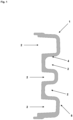
- the figures show preferred embodiments of the proposed profile structure 1.
- the figures show vertical sections through a component 20 of a machine tool 10, the profile structure 1 of the component 20 of the machine tool 10 becoming visible through this representation of the vertical section.
- the profile structure 1 has at least two beads 2, for example the 1 profile structure 1 shown has five beads 2 .
- the beads 2 are formed by channel-shaped depressions, which are preferably formed one above the other and with side walls which are formed essentially parallel.
- This in 1 illustrated embodiment of the invention has, for example, three beads 2, which are open in the direction of the left half of the figure, and two beads 2, which are open in the direction of the right half of the figure. Overall, the in 1 cutting arm shown thus five beads 2 on.
- the profile structure 1 has profile structure walls 4, which can have different thicknesses.
- the profile structure walls 4 can be made thicker in the transition areas between a bead and a profile surface of the profile structure 1 than in the area of the side walls of the beads 2.
- the outwardly facing surfaces of the component 20 of the machine tool 10 are preferably referred to as profile surfaces within the meaning of the invention.
- This in 1 The illustrated embodiment of the invention essentially represents a basic structure 5 of the profile structure 1, wherein the 1 Profile structure 1 shown has no stiffening ribs 3, for example.
- the beads 2 are in the in 1 illustrated embodiment of the invention opened on the left and closed on the right side of the figure.
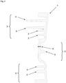
- This in 2 illustrated embodiment of the invention has a total of three beads 2, with two beads 2 are open in the direction of the left half of the figure and a bead 2 is open in the direction of the right half of the figure.
- the beads 2 and their dimensions are represented in the figures by curly brackets.
- stiffening ribs 3 which are preferably present in the beads 2 arranged.
- the stiffening ribs 3 give the profile structure 1 even greater stability and robustness.
- four stiffening ribs 3 can be seen.
- the remaining structure, which does not form a stiffening rib 3, is the basic structure 5 of the profile structure 1.
- the profile structure 1 In 3 an alternative or third embodiment of the profile structure 1 is shown.
- the 3 Profile structure 1 shown has two beads 2 and a row of stiffening ribs 3 .
- This in 3 illustrated embodiment of the invention also has a total of three beads 2, two beads 2 are open in the direction of the left half of the image and a bead 2 is open in the direction of the right half of the image.
- the beads 2 there are a number of stiffening ribs 3 which give the profile structure 1 even greater stability.
- FIG. 5 shows side views of preferred embodiments of the cutting arm 50.
- FIG 4 how the cutting arm 50 performs a torsion about a central axis D of the cutting arm 50 while in FIGS figure 5 and 6 Bends around a vertical ( figure 5 ) or a horizontal ( 6 ) Axis of the cutting arm 50 are shown.
- the central axis, as well as the vertical and horizontal axes of the cutting arm 50 are in the Figures 4 to 6 represented by dashed lines passing through the cutting arm 50 or lying within the cutting arm 50.
- the directions of bending or rotation of the cutting arm 50 for each type of load are shown in FIGS Figures 4 to 6 indicated by the round arrows at the ends of the axes.
- figure 4 12 also shows the three axes A, B and C, which can pass through different points of the cutting arm 50.
- the first axis A represents the motor axis of the machine tool 10.
- the second axis B represents the transmission axis of the machine tool 10 and is connected to one of the two pulleys of the belt drive of the machine tool 10.
- the third axis C represents the tool axis of the machine tool 10 and is connected to the other of the two pulleys of the belt drive of the machine tool 10 .
- the tool 11 of the machine tool 10 can rotate about the third or tool axis C of the proposed cutting arm 50 .
- the tool 11 can preferably be a disk-shaped tool, such as a separating or cutting disk, wherein the tool 11 is set up to rotate about the tool axis C. Furthermore, is in figure 4 the angle alpha is shown, which is preferably enclosed by the stiffening ribs 3 and the beads 2 or the stiffening ribs 3 and the torsion axis of the cutting arm 50 . In particular, the torsion axis of the cutting arm 50 coincides with the virtual central axis D of the cutting arm 50 .
Landscapes
- Engineering & Computer Science (AREA)
- Mechanical Engineering (AREA)
- Life Sciences & Earth Sciences (AREA)
- Forests & Forestry (AREA)
- Processing Of Stones Or Stones Resemblance Materials (AREA)
- Sawing (AREA)
Priority Applications (4)
| Application Number | Priority Date | Filing Date | Title |
|---|---|---|---|
| EP21192816.3A EP4140647A1 (fr) | 2021-08-24 | 2021-08-24 | Structure profilée pour un composant d'une machine-outil et machine-outil dotée d'une structure profilée |
| EP22762047.3A EP4392204A1 (fr) | 2021-08-24 | 2022-08-08 | Structure profilée pour un élément d'un outil électrique, et outil électrique doté d'une structure profilée |
| PCT/EP2022/072173 WO2023025577A1 (fr) | 2021-08-24 | 2022-08-08 | Structure profilée pour un élément d'un outil électrique, et outil électrique doté d'une structure profilée |
| US18/291,505 US20240375240A1 (en) | 2021-08-24 | 2022-08-08 | Profile structure for a component of a power tool, and power tool having a profile structure |
Applications Claiming Priority (1)
| Application Number | Priority Date | Filing Date | Title |
|---|---|---|---|
| EP21192816.3A EP4140647A1 (fr) | 2021-08-24 | 2021-08-24 | Structure profilée pour un composant d'une machine-outil et machine-outil dotée d'une structure profilée |
Publications (1)
| Publication Number | Publication Date |
|---|---|
| EP4140647A1 true EP4140647A1 (fr) | 2023-03-01 |
Family
ID=77465898
Family Applications (2)
| Application Number | Title | Priority Date | Filing Date |
|---|---|---|---|
| EP21192816.3A Withdrawn EP4140647A1 (fr) | 2021-08-24 | 2021-08-24 | Structure profilée pour un composant d'une machine-outil et machine-outil dotée d'une structure profilée |
| EP22762047.3A Pending EP4392204A1 (fr) | 2021-08-24 | 2022-08-08 | Structure profilée pour un élément d'un outil électrique, et outil électrique doté d'une structure profilée |
Family Applications After (1)
| Application Number | Title | Priority Date | Filing Date |
|---|---|---|---|
| EP22762047.3A Pending EP4392204A1 (fr) | 2021-08-24 | 2022-08-08 | Structure profilée pour un élément d'un outil électrique, et outil électrique doté d'une structure profilée |
Country Status (3)
| Country | Link |
|---|---|
| US (1) | US20240375240A1 (fr) |
| EP (2) | EP4140647A1 (fr) |
| WO (1) | WO2023025577A1 (fr) |
Citations (4)
| Publication number | Priority date | Publication date | Assignee | Title |
|---|---|---|---|---|
| US7137877B2 (en) * | 2003-06-06 | 2006-11-21 | Andreas Stihl Ag & Co Kg | Manually operated tool |
| DE102016013907A1 (de) | 2016-11-22 | 2018-05-24 | Andreas Stihl Ag & Co. Kg | Handgeführtes Arbeitsgerät |
| EP3620262A1 (fr) * | 2018-09-10 | 2020-03-11 | Hilti Aktiengesellschaft | Tronçonneuse guidée à la main |
| EP3670078A1 (fr) * | 2018-12-21 | 2020-06-24 | Hilti Aktiengesellschaft | Tronçonneuse guidée à la main |
Family Cites Families (4)
| Publication number | Priority date | Publication date | Assignee | Title |
|---|---|---|---|---|
| US8413645B2 (en) * | 2005-03-23 | 2013-04-09 | Husqvarna Ab | Cutting or sawing machine |
| US8347513B2 (en) * | 2010-12-21 | 2013-01-08 | Marshall Buster Lee | Hand-held saw with rigid frame |
| EP3670077B1 (fr) * | 2018-12-21 | 2024-05-15 | Hilti Aktiengesellschaft | Tronçonneuse guidée à la main |
| GB202102708D0 (en) * | 2021-02-25 | 2021-04-14 | Decom Eng Ltd | Cutting apparatus |
-
2021
- 2021-08-24 EP EP21192816.3A patent/EP4140647A1/fr not_active Withdrawn
-
2022
- 2022-08-08 EP EP22762047.3A patent/EP4392204A1/fr active Pending
- 2022-08-08 WO PCT/EP2022/072173 patent/WO2023025577A1/fr not_active Ceased
- 2022-08-08 US US18/291,505 patent/US20240375240A1/en active Pending
Patent Citations (4)
| Publication number | Priority date | Publication date | Assignee | Title |
|---|---|---|---|---|
| US7137877B2 (en) * | 2003-06-06 | 2006-11-21 | Andreas Stihl Ag & Co Kg | Manually operated tool |
| DE102016013907A1 (de) | 2016-11-22 | 2018-05-24 | Andreas Stihl Ag & Co. Kg | Handgeführtes Arbeitsgerät |
| EP3620262A1 (fr) * | 2018-09-10 | 2020-03-11 | Hilti Aktiengesellschaft | Tronçonneuse guidée à la main |
| EP3670078A1 (fr) * | 2018-12-21 | 2020-06-24 | Hilti Aktiengesellschaft | Tronçonneuse guidée à la main |
Also Published As
| Publication number | Publication date |
|---|---|
| EP4392204A1 (fr) | 2024-07-03 |
| US20240375240A1 (en) | 2024-11-14 |
| WO2023025577A1 (fr) | 2023-03-02 |
Similar Documents
| Publication | Publication Date | Title |
|---|---|---|
| DE69707784T2 (de) | Werkzeug mit variabler Kraft | |
| EP0453773B1 (fr) | Dispositif de démolition | |
| DE202006019496U1 (de) | Fliesenschneidemaschine | |
| DE102009035232B4 (de) | Schneidsatz für Haarschneidemaschinen | |
| EP3356073B1 (fr) | Lame de scie à ruban à dent diviseuse de copeaux | |
| DE102016112748A1 (de) | Großmanipulator mit gewichtoptimiertem Knickmast | |
| EP3664593B1 (fr) | Lame pour couteau d'une moissonneuse agricole | |
| DE202020101673U1 (de) | Kettensäge mit hoher Effizienz | |
| EP4140647A1 (fr) | Structure profilée pour un composant d'une machine-outil et machine-outil dotée d'une structure profilée | |
| EP2574226B1 (fr) | Agencement de doigts de coupe | |
| EP3637978B1 (fr) | Système de coupe à double lame | |
| DE3906351C2 (de) | Messerklinge für Mähmesser von Erntemaschinen | |
| DE102009007187A1 (de) | Sägekette und damit ausgestattete Kettensäge | |
| DE3410368A1 (de) | Werkzeug fuer kultivatoren | |
| EP3530393A1 (fr) | Lame de scie pourvue de denture de poussée et de traction | |
| EP3698619A1 (fr) | Système de lame pour une tondeuse à gazon | |
| DE102007050385B4 (de) | Haarentfernungsgerät | |
| DE3050788C2 (de) | Einschwingen - Backenbrecher | |
| DE102023102839A1 (de) | Scharnierförderband für eine Fördereinrichtung sowie Laserschneidmaschine | |
| EP2166158B1 (fr) | Grille d'entrée pour constructions d'extraction d'eau, par exemple de centrales hydroélectriques | |
| DE102010002935B4 (de) | Stabrechen | |
| EP1002904A1 (fr) | Godet d'excavatrice | |
| DE202024100908U1 (de) | Säbelsägeblatt | |
| DE8213540U1 (de) | Kreiselegge mit mehreren Werkzeugkreiseln | |
| DE102020115814A1 (de) | Baggerlöffel mit Verstärkung |
Legal Events
| Date | Code | Title | Description |
|---|---|---|---|
| PUAI | Public reference made under article 153(3) epc to a published international application that has entered the european phase |
Free format text: ORIGINAL CODE: 0009012 |
|
| STAA | Information on the status of an ep patent application or granted ep patent |
Free format text: STATUS: THE APPLICATION HAS BEEN PUBLISHED |
|
| AK | Designated contracting states |
Kind code of ref document: A1 Designated state(s): AL AT BE BG CH CY CZ DE DK EE ES FI FR GB GR HR HU IE IS IT LI LT LU LV MC MK MT NL NO PL PT RO RS SE SI SK SM TR |
|
| STAA | Information on the status of an ep patent application or granted ep patent |
Free format text: STATUS: THE APPLICATION IS DEEMED TO BE WITHDRAWN |
|
| 18D | Application deemed to be withdrawn |
Effective date: 20230902 |