EP4140661A1 - Robot assistant de laboratoire, mobile et autonome, pour un laboratoire diagnostic in vitro - Google Patents
Robot assistant de laboratoire, mobile et autonome, pour un laboratoire diagnostic in vitro Download PDFInfo
- Publication number
- EP4140661A1 EP4140661A1 EP21192807.2A EP21192807A EP4140661A1 EP 4140661 A1 EP4140661 A1 EP 4140661A1 EP 21192807 A EP21192807 A EP 21192807A EP 4140661 A1 EP4140661 A1 EP 4140661A1
- Authority
- EP
- European Patent Office
- Prior art keywords
- robot
- assistance robot
- arm
- unit
- samples
- Prior art date
- Legal status (The legal status is an assumption and is not a legal conclusion. Google has not performed a legal analysis and makes no representation as to the accuracy of the status listed.)
- Pending
Links
- 238000000338 in vitro Methods 0.000 title claims abstract description 11
- 239000003153 chemical reaction reagent Substances 0.000 claims abstract description 43
- 239000007788 liquid Substances 0.000 claims abstract description 16
- 238000004891 communication Methods 0.000 claims abstract description 14
- 238000012545 processing Methods 0.000 claims abstract description 14
- 230000003287 optical effect Effects 0.000 claims abstract description 8
- 239000012636 effector Substances 0.000 claims description 41
- 230000033001 locomotion Effects 0.000 claims description 34
- 238000000034 method Methods 0.000 claims description 25
- 238000003860 storage Methods 0.000 claims description 14
- 238000012544 monitoring process Methods 0.000 claims description 5
- 230000007613 environmental effect Effects 0.000 claims description 3
- 230000001133 acceleration Effects 0.000 claims description 2
- 238000011022 operating instruction Methods 0.000 claims description 2
- 230000003993 interaction Effects 0.000 claims 1
- 238000004458 analytical method Methods 0.000 abstract description 7
- 239000000523 sample Substances 0.000 description 24
- 238000007726 management method Methods 0.000 description 22
- 230000008569 process Effects 0.000 description 12
- 230000008901 benefit Effects 0.000 description 6
- 230000000694 effects Effects 0.000 description 6
- 230000007246 mechanism Effects 0.000 description 5
- 239000013610 patient sample Substances 0.000 description 5
- 238000002360 preparation method Methods 0.000 description 5
- 238000013461 design Methods 0.000 description 4
- 239000012530 fluid Substances 0.000 description 4
- 230000004807 localization Effects 0.000 description 4
- 238000011179 visual inspection Methods 0.000 description 4
- 241000282412 Homo Species 0.000 description 3
- 230000006378 damage Effects 0.000 description 3
- 210000002310 elbow joint Anatomy 0.000 description 3
- 238000005516 engineering process Methods 0.000 description 3
- 238000012986 modification Methods 0.000 description 3
- 230000004048 modification Effects 0.000 description 3
- 238000003752 polymerase chain reaction Methods 0.000 description 3
- 238000012360 testing method Methods 0.000 description 3
- 239000002699 waste material Substances 0.000 description 3
- 241001538338 Gambelia sila Species 0.000 description 2
- 239000008280 blood Substances 0.000 description 2
- 210000004369 blood Anatomy 0.000 description 2
- 238000004140 cleaning Methods 0.000 description 2
- 238000011156 evaluation Methods 0.000 description 2
- 210000004247 hand Anatomy 0.000 description 2
- 238000003018 immunoassay Methods 0.000 description 2
- 238000013507 mapping Methods 0.000 description 2
- 238000005259 measurement Methods 0.000 description 2
- 238000003909 pattern recognition Methods 0.000 description 2
- 230000008447 perception Effects 0.000 description 2
- 230000003068 static effect Effects 0.000 description 2
- 229920001817 Agar Polymers 0.000 description 1
- 208000025721 COVID-19 Diseases 0.000 description 1
- 238000010521 absorption reaction Methods 0.000 description 1
- 230000015572 biosynthetic process Effects 0.000 description 1
- 238000001816 cooling Methods 0.000 description 1
- 238000012937 correction Methods 0.000 description 1
- 238000000151 deposition Methods 0.000 description 1
- 238000001514 detection method Methods 0.000 description 1
- 238000011161 development Methods 0.000 description 1
- 239000006260 foam Substances 0.000 description 1
- 230000006870 function Effects 0.000 description 1
- 230000023597 hemostasis Effects 0.000 description 1
- 238000005286 illumination Methods 0.000 description 1
- 208000015181 infectious disease Diseases 0.000 description 1
- 230000002458 infectious effect Effects 0.000 description 1
- 238000007689 inspection Methods 0.000 description 1
- 210000001503 joint Anatomy 0.000 description 1
- 238000004519 manufacturing process Methods 0.000 description 1
- 239000003550 marker Substances 0.000 description 1
- -1 other robotic arms Substances 0.000 description 1
- 238000004806 packaging method and process Methods 0.000 description 1
- 239000002245 particle Substances 0.000 description 1
- 230000007170 pathology Effects 0.000 description 1
- 238000000275 quality assurance Methods 0.000 description 1
- 230000035939 shock Effects 0.000 description 1
- 230000011664 signaling Effects 0.000 description 1
- 238000012549 training Methods 0.000 description 1
- 210000002700 urine Anatomy 0.000 description 1
- 210000000707 wrist Anatomy 0.000 description 1
Images



Classifications
-
- B—PERFORMING OPERATIONS; TRANSPORTING
- B25—HAND TOOLS; PORTABLE POWER-DRIVEN TOOLS; MANIPULATORS
- B25J—MANIPULATORS; CHAMBERS PROVIDED WITH MANIPULATION DEVICES
- B25J11/00—Manipulators not otherwise provided for
- B25J11/008—Manipulators for service tasks
-
- B—PERFORMING OPERATIONS; TRANSPORTING
- B25—HAND TOOLS; PORTABLE POWER-DRIVEN TOOLS; MANIPULATORS
- B25J—MANIPULATORS; CHAMBERS PROVIDED WITH MANIPULATION DEVICES
- B25J11/00—Manipulators not otherwise provided for
- B25J11/008—Manipulators for service tasks
- B25J11/009—Nursing, e.g. carrying sick persons, pushing wheelchairs, distributing drugs
-
- B—PERFORMING OPERATIONS; TRANSPORTING
- B25—HAND TOOLS; PORTABLE POWER-DRIVEN TOOLS; MANIPULATORS
- B25J—MANIPULATORS; CHAMBERS PROVIDED WITH MANIPULATION DEVICES
- B25J5/00—Manipulators mounted on wheels or on carriages
- B25J5/007—Manipulators mounted on wheels or on carriages mounted on wheels
-
- G—PHYSICS
- G05—CONTROLLING; REGULATING
- G05D—SYSTEMS FOR CONTROLLING OR REGULATING NON-ELECTRIC VARIABLES
- G05D1/00—Control of position, course, altitude or attitude of land, water, air or space vehicles, e.g. using automatic pilots
- G05D1/02—Control of position or course in two dimensions
- G05D1/021—Control of position or course in two dimensions specially adapted to land vehicles
- G05D1/0268—Control of position or course in two dimensions specially adapted to land vehicles using internal positioning means
- G05D1/0274—Control of position or course in two dimensions specially adapted to land vehicles using internal positioning means using mapping information stored in a memory device
Definitions
- the present invention is in the field of in-vitro diagnostics in connection with the field of robotics and relates in particular to a mobile autonomous collaborative assistance robot, a system with several such assistance robots and a method for the automated movement and / or manipulation of objects, such as liquid (Patient) samples, reagents and other consumables.
- samples that are analyzed in an IVD laboratory are subject to high processing requirements. For example, samples often have to be processed and contacted with reagents within specified time periods and/or under specific physical conditions (eg, refrigerated).
- the routes available for transporting the samples and reagents are often spatially limited and complicated movement sequences must be carried out to transport these samples and/or reagents (e.g. opening/closing a refrigerator and filling and/or removing samples and reagents from high and low shelving systems).
- Other consumables e.g. cuvettes, sample tips, cleaning liquids
- the samples can be infectious, so special safety precautions during transport and must be complied with when depositing these samples, which reliably prevent the sample content from "spilling over”.
- the identification device can be designed, for example, for electronically detecting (reading) a digital code (e.g. barcodes).
- a digital code e.g. barcodes
- the identification direction, the visual inspection device can also include other technical components, such as an illumination mechanism and a camera, in order to provide additional functionality.
- the sensor unit can comprise a set of similar or different types of sensors, such as optical sensors, LIDAR sensors, RADAR sensors and/or tactile sensors, such as force sensors or inertial sensors in fairings or exposed surfaces.
- sensors such as optical sensors, LIDAR sensors, RADAR sensors and/or tactile sensors, such as force sensors or inertial sensors in fairings or exposed surfaces.
- the identification device sometimes serves to identify the moved and/or manipulated objects (in particular the transported samples, reagents and other consumables) and their contents.
- the identification device can include an optical sensor and in particular can be designed as a scanner for a two-dimensional code, such as a QR code or barcode.
- the identification device and the sensor unit can be identical or integrated in one component.
- the identification device can also be designed to carry out contactless identification methods, for example based on RFID.
- the identification device can also be designed to identify external devices based on external features and localize and identify manipulation points (eg gripping points on the device). This has the technical effect that the identification device or the signals collected with it can also be used to specifically control the robot for opening/closing or otherwise operating doors and/or covers via handle elements.
- the robot can include a storage area in which at least one object to be transported and in particular a liquid sample and/or reagents can be placed.
- the storage area can be temperature-controlled and in particular can be designed as a cool box or warm box.
- the storage area can include shelf or frame-like attachments in order to be able to accommodate and transport a large number of so-called trays, racks or packs or sample holders in a space-saving manner.
- the temperature of the temperature-controlled samples is continuously or event-based (e.g. when inserting or adding a new object) monitored and/or electronically logged. This has the technical advantage that continuous monitoring and time savings as well as quality assurance can be provided.
- the robot can comprise a shock absorption system. This has the advantage that dangerous samples can be moved without vibration.
- the end effector can be fastened to the front arm segment via an adapter/changing system, which enables flexible exchange of different end effectors (e.g. "robot grippers or hands") for different tasks.
- an adapter/changing system which enables flexible exchange of different end effectors (e.g. "robot grippers or hands") for different tasks.
- the at least one gripping arm can be designed as a telescopic arm.
- the telescopic arm can be designed as a telescopic arm with force measurement and/or force-sensitive movements for carrying out collaborative activities. This has the technical effect that the robotic arm can sometimes collaborate with other end effectors, other robotic arms, components, devices and/or humans.
- an auxiliary joint with a horizontal axis of rotation can be added.
- the additional joint can be attached to different positions of the gripping arm and in particular to the adapter and/or end effector.
- the additional joint can perform a pivoting movement in the vertical direction, for example, the Improve accessibility to hard-to-reach objects (e.g., at the very back, at the top, or at the bottom of a shelf).
- the at least one gripping arm can be controlled with gripping instructions for gripping the objects and/or with operating instructions for manipulating, in particular for opening and/or closing external devices and/or internal components.
- the identification device and/or sensor unit allows/allow in particular the identification and localization of manipulation points for manipulating (e.g. opening and/or closing, lifting, etc.) of external devices and/or internal components and correspondingly more precise positioning relative to the external device (e.g. drawer from Recognizing and operating the analyzer with the appropriate grip point).
- the at least one gripper arm can be positioned in a transport position that does not protrude beyond an outer contour of the assistance robot when the assistance robot is moving.
- the at least one gripper arm can be controlled in a coordinated manner with the driving movement of the assistance robot in order to fulfill a manipulation task.
- the gripper arm can carry out gripping movements and/or manipulations of objects in an area that does not protrude beyond the outer contour of the assistance robot body, independently of the travel movement of the assistance robot.
- the sensor unit can comprise a MEMS module and/or an optical sensor unit, an acceleration sensor unit, a LIDAR, radar and/or sonar sensor unit, a gyroscope unit, a force and/or torque sensor unit, an acoustic sensor unit , a temperature measuring unit and/or a sensor unit for detecting environmental conditions, in particular humidity and/or temperature.
- capacitive sensors or resistive sensors e.g. for tactile applications
- the components of the sensor unit can be arranged on the body or the mobile platform, on the robot arm or on the other components of the robot and/or on devices in the medical field (analyzer, refrigerator).
- the assistance robot can be designed with a user interface (UI). be that is intended to display the objects currently being transported and/or stored and/or meta information, comprising a time period, an identification of the respective object and/or a representation of the pending tasks.
- UI user interface
- the UI can be used to receive urgent and/or unplanned tasks from staff.
- a scheduler can be provided for this purpose, which orchestrates and controls the fleet of robots at a higher level. The scheduler can run a decision algorithm to decide e.g. if the robot the UI is attached to does not run the task because it is done manually - by staff - or if another robot would be more suitable considering the overall workflow and can instruct them to do so (with corresponding feedback via the UI).
- a modification algorithm can be executed cumulatively or alternatively on the assistance robot.
- the modification algorithm serves to verify the pending planned tasks and/or to modify the tasks.
- user inputs on the UI are processed by the modification algorithm.
- This has the technical effect that pre-planned workflows can be changed locally if e.g. B. priorities should be changed due to current events.
- the UI can be attached locally to the assistance robot.
- the UI may alternatively or cumulatively be located at a remote location (eg, on a mobile device such as a tablet located elsewhere). Both are also possible in order to be able to provide outputs both locally and at a higher-level control unit.
- the UI does not necessarily have to be permanently connected to the assistant robot; a data connection is sufficient.
- the UI can also be designed as an acoustic UI in order to implement voice control of the robot. Cumulatively or alternatively, the UI can also include simple status indicators, such as LEDs, emergency stop signaling devices, etc.
- an auxiliary unit can interact with the identification device.
- a pattern recognition algorithm can be executed on the auxiliary unit and/or on the identification device, which algorithm is designed to automatically carry out the visual inspection, e.g. for the preparation of reagents.
- the pattern recognition algorithm can, for example, be designed to recognize foam formation and/or to distribute particles in the reagent pack on the basis of optical measurement data.
- the invention relates to a system for moving and/or manipulating objects, in particular samples, in particular liquid samples and/or reagents and/or devices, in a medical work area, in particular in an in vitro diagnostic laboratory for analyzing the Samples with a large number of mobile autonomous collaborative assistance robots, as described above, which are in data exchange with one another and which are controlled locally and/or by a higher-level fleet control program.
- the (multiple) mobile autonomous collaborative assistance robots can also collaborate to fulfill a common task, e.g. B. transferred objects to another robot in order to improve the efficiency of the processes or to carry out manipulations that are reserved for special robots.
- the assistance robots can also solve a task together, eg move heavy loads.
- Analysis systems from different manufacturers are used in in-vitro diagnostic laboratories (reference laboratories or hospitals) for different areas of application (e.g. clinical chemistry, immunoassay, hematology, hemostasis, molecular diagnostics, microbiology).
- Siemens Healthineers offers a broad portfolio here, for example highly flexible solutions for clinical chemistry and immunodiagnostics.
- the system consists of three basic components: sample handler, clinical chemistry system and immunoassay system.
- sample handler As a central connecting element between sample intake and analysis systems
- a magnetic sample transport technology enables completely new options for the control and monitoring of the samples.
- the systems are usually operated by their own process managers in terms of process technology. This allows workflows and processes to be controlled and made more efficient while at the same time optimizing clinical operations to save time and money. This leads to increased staff productivity, including a centralized view with the ability to control all systems from a single screen, as well as view reagent inventory and test exception rules.
- the IVD systems are also connected to laboratory information systems (LIS) or laboratory information management systems (LIMS) for the purpose of higher-level laboratory administration.
- LIS laboratory information systems
- LIMS laboratory information management systems
- the present invention proposes an automatic laboratory assistance system, which is described in more detail below in connection with the figures.
- the autonomous laboratory robot should be able to automatically operate IVD systems/devices from Siemens Healthineers, but also from external manufacturers with the functions/technologies presented.
- static data e.g. laboratory layout, building information via static map, device layout/design via CAD models and real images
- dynamic data e.g. from LIS, LIMS, middleware software, digital images of the environment, objects, people, dynamic movement data etc.
- LIS, LIMS, middleware software digital images of the environment, objects, people, dynamic movement data etc.
- the software algorithm is self-learning and self-optimizing (e.g. optimal execution of a task such as opening a lid of an IVD device).
- fixed or detachable mechanical auxiliary devices for manipulating objects can be configured on the autonomous laboratory robot, for example to be able to open and/or close drawers or covers on the IVD systems/devices.
- Other fixed auxiliary devices may also be necessary, for example to open packaging for reagents or bags of consumables such as cuvettes, to close used (but not yet completely empty) reagent packs or to close patient samples (patient tubes), etc.
- an integrated cooling unit (15-25 degrees Celsius or 2-8 degrees Celsius) can be designed for the transport of blood samples and/or the transport of reagents.
- an integrated feeder for cuvettes, sample tips (sample tips) and other consumables can be designed.
- the robot can provide or interact with an integrated storage system/transport system for PCR microplates of various types for the application area of molecular diagnostics based on PCR (polymerase chain reaction).
- the robot can be designed for IVD laboratories. Cumulatively or alternatively, it can also be designed for operation in pathology and/or microbiology with corresponding microbiology panels or petri dishes.
- the laboratory robot should be able to operate the device operation of laboratory and/or medical devices and in particular IVD devices from different manufacturers automatically and autonomously.
- Existing solutions are not mobile (stationary robots) and automate tasks in logistics or pre- and post-analytics, but not in analytics itself (operation of IVD systems/devices).
- the autonomous laboratory robot is mobile or portable and navigates through its environment to solve the task assigned to it without colliding.
- a mobile robot with comparable kinematics is also suitable as an assistant in the medical care of patients and in operating rooms, e.g. to deliver consumables from the non-sterile area to the sterile team during the operation and to hand them over sterile.
- the robot is constructed in such a way that it has at least the working space normally accessible to human employees (near the floor up to a height of approx. 1.8 to 2 meters) and horizontal range 0.5 ... 0.7 meters completely and can also interact with and/or manipulate and/or move fragile objects (because they are liquid samples) without causing damage. It has sufficient carrying capacity to be able to fully perform the tasks that are usual for human employees. He is also trained to perceive the environment appropriately for a safe and collision-free movement and to localize objects that are to be gripped and handled.
- the robot autonomously carries out the tasks assigned to it and, in particular, previously trained tasks in different environments and under changing conditions.
- the robot has a robust structure for reliable operation and a high degree of availability. The cost of manufacturing and maintaining the robot is relatively low.
- a significant disadvantage of robots known from the prior art can be seen in the fact that the known cobot solutions use articulated arm kinematics with 6 or 7 degrees of freedom, which essentially cover a spherical working space. Because of their kinematics, they can For example, access to the upper and lower levels of storage racks, which are easily reached by humans, is very limited. With increasing range, ie with increasing torque requirement in the joints, the possible load capacity of this type of robot is reduced. The lengthening of the arm segments to increase the reach of articulated robots makes access in cramped areas more difficult. The elbow joint and the spatial orientation of the arm segments often leads to collisions in the area.
- Robots with pure joint kinematics as in the prior art often require complex trajectories for relatively simple handling such.
- the movements of the robot arms essentially only take place in a horizontal plane and are therefore less complex than the spatial movements of conventional articulated robots.
- the entire working area can be covered in a relatively simple and easily manageable manner.
- the risk of the robot arm colliding is always limited to the height range in which it is currently positioned by the lifting axis. In the case of three-dimensional articulated robots, there are also risks of collision in other height ranges through which the arm reaches.
- the proposed robot kinematics uses a linear lifting axis that can be rotated through at least 360°.
- the robot arm attached to it can thus reach the surrounding cylinder volume without restrictions.
- the cylindrical workspace enables significantly better accessibility at all heights. Due to the horizontal orientation, the robotic arm can reach and handle objects on all levels without restrictions, from near the floor to the upper limit of the workspace. Cameras and/or other sensor systems can be attached to the lifting axle, which are always aligned with the rotation of the lifting axle to the working area of the robot arm remain.
- the robot arm can, for example, reach a large segment next to the mobile platform down to floor level. Above the mobile platform, the robotic arm can reach the entire area all around without restrictions.
- a laboratory assistance robot 100 (referred to below as robot) is shown.
- the robot has a drive device 104 and is therefore mobile.
- the robot 100 has a space-saving design and can have a predominantly rectangular or cylindrical three-dimensional shape.
- the robot 100 includes a navigation unit 101, a local processor unit 102, a digital interface in the form of a communication unit 103 for exchanging data, control instructions, sensor data and/or applications.
- the robot 100 comprises an energy supply device 105 for local energy supply and an identification device 108 for the unique identification of the objects and in particular the samples and reagents and preferably also for the identification of the contents of sample tubes or reagents.
- the robot 100 also has a storage area 109 for receiving sample containers (tubes), reagent packs, trays, racks and/or other objects that are relevant to the analysis of samples and may have to be transported.
- the storage area 109 can comprise a number of segments which are arranged at different positions of the robot 100 .
- one of the segments can be located on an upper side of a body 106 of the robot 100 in order to be able to ensure, for example, that objects can be stored quickly.
- a segment can be formed on an outer edge of the body 106, which is shaped like a shelf. The segment may be located above the body 106 of the robot 100 or may be cantilevered slightly outwardly at an angle.
- the robot 100 also includes a lifting axis H, which is rotatably mounted on the body 106 .
- the lifting axis H extends extends essentially vertically upwards and has a preferably predominantly vertical central longitudinal axis.
- On the lifting axis H a vertically movable and rotatable about the lifting axis H carriage S is mounted.
- On the carriage S a gripper arm G is attached, which can move perpendicular to the lifting axis H with its components substantially.
- the gripping arm G can rotate about the axis H in an angular range between 0° and 360°.
- At least one end effector G3 can be arranged at the end of the gripping arm G that is remote from the lifting arm. The end effector G3 is used to interact with the objects and, for example, to grip and/or put down the sample containers or reagent packs.
- the lifting axis H is preferably arranged in a corner area of the body 106 and thus borders on a short edge and on a long edge of the body 106 .
- This has the technical advantage that the largest possible area on an upper side of the body 106 can be used as a storage area 109 or for other functionalities.
- the exact positioning of the named components of the robot 100 can be varied depending on the embodiment.
- FIG. 12 shows a schematic representation of a top view of a robot 100.
- the outer contour of the body 106 is approximately rectangular and has rounded edges in order to simplify the movement and operation of the robot 106.
- FIG. The lifting axis H is arranged in the lower left corner area and carries the gripping arm G.
- the gripping arm G comprises a rear arm segment G1 and a front arm segment G2 as well as an end effector G3.
- the end effector G3 can be attached directly to the front arm segment G2.
- the end effector G3 is not attached directly and immediately to the front arm segment G2, but only indirectly via an adapter G4.
- the G4 adapter serves as a changing device.
- the gripping arm G can have a modular design and can be easily exchanged made possible by different end effectors G3. This means that the system can be easily and flexibly adapted to the respective application.
- the joint axes of the respective joint connections for the arm segments G1, G2, G3 run—corresponding to the stroke axis H—essentially vertically.
- FIG. 3 shows in a further overview an embodiment in which two gripping arms G are mounted on the lifting axis H.
- more than two gripping arms G can also be formed on the robot 100 .
- the respective end effectors G3 of the two gripping arms G can preferably be controlled in such a way that they are controlled together in a coordinated manner in order to solve a task together, such as holding objects and holding them at the same time, which is the case, for example, when opening/closing closures is required.
- the platform can also have more than one lifting axis.
- a lifting axis could be formed on opposite edges of the platform, on which gripping arms and/or other components are mounted.
- the lifting axis H here extends approximately over the same height as the body 106.
- a sensor device 107 and in particular a camera can be arranged in the upper area of the lifting axis H.
- a further sensor device 107 can be arranged below the gripping arm G on the carriage. This is particularly useful if the end effector G3 (cf. 2 , in 3 not designated separately) seized objects are mainly below a plane of movement of the gripper arm G are.
- the camera 107 can also be arranged above the gripping arm G if the area to be detected by sensors is mainly above the plane of rotation of the gripping arm G.
- the lifting axis H carries three gripping arms G at different height sections.
- the respective end effectors G3 of the gripping arms G can be positioned and designed to deposit the objects gripped in storage areas 109 which are located inside the robot 100 and in particular inside the body 106 of the robot 100 .
- the robot 100 may further include a user interface UI.
- the user interface UI can be formed in a height range on an outer wall of the body 106 which corresponds approximately to the eye level of a standing person in order to enable ergonomic operation of the user interface.
- the user interface UI (human machine interface) can be designed in particular as a touch panel with a touch-sensitive display.
- the cameras 107 are preferably arranged in such a way that they detect the different storage areas 109 of the robot 100 . This enables the correct positioning of the objects to be assured. An additional monitoring functionality can thus be provided. This increases the safety of the automatic, robot-based system.
- the data recorded by sensors (in particular the data from the camera 107) can be processed locally on a processing unit of the robot and/or centrally on a server connected via a corresponding wireless data connection.
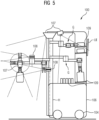
- figure 5 1 shows, in a schematic side view of a robot 100, an exemplary embodiment in which the robot 100 has a separate identification device 108 in addition to the sensor device 107.
- the identification device 108 can be a laser scanner, for example.
- the laser scanner 108 can be arranged, for example, on the gripping arm G and in particular on a joint in the upper area. This has the advantage that the objects to be transported those of the end effector G3 (cf. 2 , in figure 5 not explicitly designated) can be picked up and/or put down in a simple manner and can be detected by the laser scanner 108 essentially without any additional movements.
- the signals (image data) detected by sensor device 107 and/or by identification device 108 are processed further by local processor unit 102 and/or by a central processing unit (not shown here), which is connected to local processor unit 102 via a corresponding data connection. namely via the communication device 103 (cf. 1 ).
- the recorded data can be fed back to control the robot 100 .
- step S2 shows a flow chart of a method according to a preferred embodiment of the invention.
- a digital task for the robot 100 is read in from a digital representation of a task list in step S1.
- step S2 local and/or global trajectory planning is carried out to process the task.
- the movement paths of the robot 100, the movement paths of the corresponding end effectors G3 and/or the height adjustment of the lifting axis are defined.
- step S31 control instructions are calculated and/or in step S32 control instructions are read in via the communication unit or recorded by the central processing unit. The control instructions are used to process the task.
- sensor signals are recorded during processing of the task, which may have multiple steps.
- step S5 the sensor signals can—as already described above—either be communicated to the internal processor unit and processed locally and/or forwarded via the communication device to an external processor unit for processing there become.
- the method can be divided into two time phases: in a first second phase t1, planning steps can be carried out, in particular steps S1, S2, S31, S32, and in a second time phase t2, the laboratory assistance robot can be controlled to carry out the task assigned to it, with the steps S4, S5.
- An advantageous feature of the invention and of the assistance robot is the use of a rotatable lifting axis as a carrier for the robot arm, so that a cylindrical working space from floor height to about 2 m in height can be covered. At the same time, a high payload is achieved and the robot arm has good accessibility to the various levels on which handling or access is to take place.
- the invention can be applied not only to movement and manipulation tasks in IVD laboratories, but also to other robot-assisted devices used in clinical operations and for example, be used intra-operatively in the operating room.
- the components of the robot and/or system can be distributed over a number of physical products in order to form a distributed system.
Landscapes
- Engineering & Computer Science (AREA)
- Mechanical Engineering (AREA)
- Robotics (AREA)
- Radar, Positioning & Navigation (AREA)
- Nursing (AREA)
- General Health & Medical Sciences (AREA)
- Health & Medical Sciences (AREA)
- Aviation & Aerospace Engineering (AREA)
- Remote Sensing (AREA)
- Physics & Mathematics (AREA)
- General Physics & Mathematics (AREA)
- Automation & Control Theory (AREA)
- Manipulator (AREA)
Priority Applications (3)
| Application Number | Priority Date | Filing Date | Title |
|---|---|---|---|
| EP21192807.2A EP4140661A1 (fr) | 2021-08-24 | 2021-08-24 | Robot assistant de laboratoire, mobile et autonome, pour un laboratoire diagnostic in vitro |
| DE202022103719.1U DE202022103719U1 (de) | 2021-08-24 | 2022-07-05 | Autonomer mobiler Laborassistenzroboter für ein in vitro diagnostisches Labor |
| CN202222242059.4U CN221883667U (zh) | 2021-08-24 | 2022-08-24 | 移动式自主协作辅助机器人和用于在医学工作区域中移动和/或操纵物体的系统 |
Applications Claiming Priority (1)
| Application Number | Priority Date | Filing Date | Title |
|---|---|---|---|
| EP21192807.2A EP4140661A1 (fr) | 2021-08-24 | 2021-08-24 | Robot assistant de laboratoire, mobile et autonome, pour un laboratoire diagnostic in vitro |
Publications (1)
| Publication Number | Publication Date |
|---|---|
| EP4140661A1 true EP4140661A1 (fr) | 2023-03-01 |
Family
ID=77465894
Family Applications (1)
| Application Number | Title | Priority Date | Filing Date |
|---|---|---|---|
| EP21192807.2A Pending EP4140661A1 (fr) | 2021-08-24 | 2021-08-24 | Robot assistant de laboratoire, mobile et autonome, pour un laboratoire diagnostic in vitro |
Country Status (3)
| Country | Link |
|---|---|
| EP (1) | EP4140661A1 (fr) |
| CN (1) | CN221883667U (fr) |
| DE (1) | DE202022103719U1 (fr) |
Cited By (2)
| Publication number | Priority date | Publication date | Assignee | Title |
|---|---|---|---|---|
| WO2024251773A1 (fr) | 2023-06-07 | 2024-12-12 | Mvz Medizinische Labore Dessau Kassel Gmbh | Installation de laboratoire de diagnostic in vitro comprenant des dispositifs d'analyse et un robot de manipulation avec au moins deux bras de préhension et une table avec une surface de support |
| EP4617671A1 (fr) | 2024-03-11 | 2025-09-17 | MVZ Medizinische Labore Dessau Kassel GmbH | Dispositif de diagnostic in vitro en laboratoire et son procédé de fonctionnement |
Families Citing this family (1)
| Publication number | Priority date | Publication date | Assignee | Title |
|---|---|---|---|---|
| DE102023120216A1 (de) | 2023-07-28 | 2025-01-30 | Fricke Abfülltechnik GmbH & Co. KG | Arbeitsplatz an einer Duftorgel |
Citations (5)
| Publication number | Priority date | Publication date | Assignee | Title |
|---|---|---|---|---|
| JPH09267276A (ja) * | 1996-03-30 | 1997-10-14 | Technol Res Assoc Of Medical & Welfare Apparatus | 搬送ロボットシステム |
| JP2001278409A (ja) * | 2000-03-31 | 2001-10-10 | Nippon Shooter Ltd | 検体搬送車およびこれを用いた検体搬送システム |
| US20190242916A1 (en) * | 2018-02-02 | 2019-08-08 | HighRes Biosolutions, Inc. | Auto-navigating robotic processing vehicle |
| CN110434862A (zh) * | 2019-07-15 | 2019-11-12 | 大连大华中天科技有限公司 | 一种手臂可升降式全向移动复合型护理机器人 |
| DE102019216785A1 (de) * | 2019-10-30 | 2021-05-06 | Kuka Deutschland Gmbh | Mobile Pflegeassistenzvorrichtung und Patiententransport-Logistiksystem |
-
2021
- 2021-08-24 EP EP21192807.2A patent/EP4140661A1/fr active Pending
-
2022
- 2022-07-05 DE DE202022103719.1U patent/DE202022103719U1/de active Active
- 2022-08-24 CN CN202222242059.4U patent/CN221883667U/zh active Active
Patent Citations (5)
| Publication number | Priority date | Publication date | Assignee | Title |
|---|---|---|---|---|
| JPH09267276A (ja) * | 1996-03-30 | 1997-10-14 | Technol Res Assoc Of Medical & Welfare Apparatus | 搬送ロボットシステム |
| JP2001278409A (ja) * | 2000-03-31 | 2001-10-10 | Nippon Shooter Ltd | 検体搬送車およびこれを用いた検体搬送システム |
| US20190242916A1 (en) * | 2018-02-02 | 2019-08-08 | HighRes Biosolutions, Inc. | Auto-navigating robotic processing vehicle |
| CN110434862A (zh) * | 2019-07-15 | 2019-11-12 | 大连大华中天科技有限公司 | 一种手臂可升降式全向移动复合型护理机器人 |
| DE102019216785A1 (de) * | 2019-10-30 | 2021-05-06 | Kuka Deutschland Gmbh | Mobile Pflegeassistenzvorrichtung und Patiententransport-Logistiksystem |
Cited By (2)
| Publication number | Priority date | Publication date | Assignee | Title |
|---|---|---|---|---|
| WO2024251773A1 (fr) | 2023-06-07 | 2024-12-12 | Mvz Medizinische Labore Dessau Kassel Gmbh | Installation de laboratoire de diagnostic in vitro comprenant des dispositifs d'analyse et un robot de manipulation avec au moins deux bras de préhension et une table avec une surface de support |
| EP4617671A1 (fr) | 2024-03-11 | 2025-09-17 | MVZ Medizinische Labore Dessau Kassel GmbH | Dispositif de diagnostic in vitro en laboratoire et son procédé de fonctionnement |
Also Published As
| Publication number | Publication date |
|---|---|
| CN221883667U (zh) | 2024-10-22 |
| DE202022103719U1 (de) | 2022-10-12 |
Similar Documents
| Publication | Publication Date | Title |
|---|---|---|
| DE202022103719U1 (de) | Autonomer mobiler Laborassistenzroboter für ein in vitro diagnostisches Labor | |
| US20250093374A1 (en) | Integrated laboratory system with autonomous mobile robots | |
| Rahman et al. | Cobotics: the evolving roles and prospects of next‐generation collaborative robots in Industry 5.0 | |
| Indri et al. | Smart sensors applications for a new paradigm of a production line | |
| EP2918378B1 (fr) | Procédé de recherche de chemin dans un système de manipulation automatisé et système de manipulation doté d'un module de commande correspondant destiné à la recherche de chemin | |
| DE102020114577A1 (de) | Steuerung und steuerverfahren für robotersystem | |
| EP2884285B1 (fr) | Module d'alimentation pour analyseur automatisé | |
| DE10305384A1 (de) | Verfahren und Vorrichtung zur Visualisierung rechnergestützter Informationen | |
| DE102017120378A1 (de) | Innenraum-ortung-basierte steuerung von fertigungsprozessen in der metallverarbeitenden industrie | |
| KR20260009282A (ko) | 세포 처리 시스템으로부터의 유체 샘플의 자동 분석을 위한 시스템, 디바이스, 및 방법 | |
| DE202018101231U1 (de) | Greifer zum positionsgenauen Greifen mindestens eines Bauteils für eine Vorbereitung einer Bauteilbehandlung | |
| Righettini et al. | Neural network mapping of industrial robots’ task times for real-time process optimization | |
| CN120572528A (zh) | 用于实验室自动化的柔性复合机器人系统 | |
| Liu et al. | Mobile robotic transportation in laboratory automation: Multi-robot control, robot-door integration and robot-human interaction | |
| Huang et al. | Mobile robots in automated laboratory workflows | |
| DE102018109329B4 (de) | Mehrgliedrige aktuierte Kinematik, vorzugsweise Roboter, besonders vorzugsweise Knickarmroboter | |
| Wurll et al. | Production logistics with mobile robots | |
| Parkinson et al. | Assessment of the utilization of quadruped robots in pharmaceutical research and development laboratories | |
| DE102019200930A1 (de) | Vorrichtung und Verfahren zum automatischen Handhaben von Lagereinheiten | |
| WO2025153458A1 (fr) | Système de manipulation automatique de composants dans un processus de montage | |
| Singhai et al. | Applied mathematics for pharmaceutical problems using robotics as assistive tools for learning: a comprehensive review | |
| DE102021101213A1 (de) | Kommissioniersystem | |
| US20250103015A1 (en) | Laboratory automation using labware movement | |
| Tiwari et al. | Artificial Intelligence and Robotics: A Step Forward Towards Drug Discovery | |
| Barua et al. | Modernization of robotics application in 21st century: A review |
Legal Events
| Date | Code | Title | Description |
|---|---|---|---|
| PUAI | Public reference made under article 153(3) epc to a published international application that has entered the european phase |
Free format text: ORIGINAL CODE: 0009012 |
|
| STAA | Information on the status of an ep patent application or granted ep patent |
Free format text: STATUS: THE APPLICATION HAS BEEN PUBLISHED |
|
| AK | Designated contracting states |
Kind code of ref document: A1 Designated state(s): AL AT BE BG CH CY CZ DE DK EE ES FI FR GB GR HR HU IE IS IT LI LT LU LV MC MK MT NL NO PL PT RO RS SE SI SK SM TR |
|
| STAA | Information on the status of an ep patent application or granted ep patent |
Free format text: STATUS: REQUEST FOR EXAMINATION WAS MADE |
|
| 17P | Request for examination filed |
Effective date: 20230829 |
|
| RBV | Designated contracting states (corrected) |
Designated state(s): AL AT BE BG CH CY CZ DE DK EE ES FI FR GB GR HR HU IE IS IT LI LT LU LV MC MK MT NL NO PL PT RO RS SE SI SK SM TR |
|
| RAP1 | Party data changed (applicant data changed or rights of an application transferred) |
Owner name: SIEMENS HEALTHINEERS AG |