EP4140777B1 - System und verfahren zur schätzung der reifenlast - Google Patents
System und verfahren zur schätzung der reifenlast Download PDFInfo
- Publication number
- EP4140777B1 EP4140777B1 EP22191779.2A EP22191779A EP4140777B1 EP 4140777 B1 EP4140777 B1 EP 4140777B1 EP 22191779 A EP22191779 A EP 22191779A EP 4140777 B1 EP4140777 B1 EP 4140777B1
- Authority
- EP
- European Patent Office
- Prior art keywords
- tire
- footprint length
- vehicle
- footprint
- processor
- Prior art date
- Legal status (The legal status is an assumption and is not a legal conclusion. Google has not performed a legal analysis and makes no representation as to the accuracy of the status listed.)
- Active
Links
Images


Classifications
-
- B—PERFORMING OPERATIONS; TRANSPORTING
- B60—VEHICLES IN GENERAL
- B60C—VEHICLE TYRES; TYRE INFLATION; TYRE CHANGING; CONNECTING VALVES TO INFLATABLE ELASTIC BODIES IN GENERAL; DEVICES OR ARRANGEMENTS RELATED TO TYRES
- B60C23/00—Devices for measuring, signalling, controlling, or distributing tyre pressure or temperature, specially adapted for mounting on vehicles; Arrangement of tyre inflating devices on vehicles, e.g. of pumps or of tanks; Tyre cooling arrangements
- B60C23/02—Signalling devices actuated by tyre pressure
- B60C23/04—Signalling devices actuated by tyre pressure mounted on the wheel or tyre
-
- G—PHYSICS
- G01—MEASURING; TESTING
- G01L—MEASURING FORCE, STRESS, TORQUE, WORK, MECHANICAL POWER, MECHANICAL EFFICIENCY, OR FLUID PRESSURE
- G01L17/00—Devices or apparatus for measuring tyre pressure or the pressure in other inflated bodies
- G01L17/005—Devices or apparatus for measuring tyre pressure or the pressure in other inflated bodies using a sensor contacting the exterior surface, e.g. for measuring deformation
-
- B—PERFORMING OPERATIONS; TRANSPORTING
- B60—VEHICLES IN GENERAL
- B60C—VEHICLE TYRES; TYRE INFLATION; TYRE CHANGING; CONNECTING VALVES TO INFLATABLE ELASTIC BODIES IN GENERAL; DEVICES OR ARRANGEMENTS RELATED TO TYRES
- B60C11/00—Tyre tread bands; Tread patterns; Anti-skid inserts
- B60C11/24—Wear-indicating arrangements
- B60C11/246—Tread wear monitoring systems
-
- B—PERFORMING OPERATIONS; TRANSPORTING
- B60—VEHICLES IN GENERAL
- B60C—VEHICLE TYRES; TYRE INFLATION; TYRE CHANGING; CONNECTING VALVES TO INFLATABLE ELASTIC BODIES IN GENERAL; DEVICES OR ARRANGEMENTS RELATED TO TYRES
- B60C23/00—Devices for measuring, signalling, controlling, or distributing tyre pressure or temperature, specially adapted for mounting on vehicles; Arrangement of tyre inflating devices on vehicles, e.g. of pumps or of tanks; Tyre cooling arrangements
- B60C23/06—Signalling devices actuated by deformation of the tyre, e.g. tyre mounted deformation sensors or indirect determination of tyre deformation based on wheel speed, wheel-centre to ground distance or inclination of wheel axle
- B60C23/064—Signalling devices actuated by deformation of the tyre, e.g. tyre mounted deformation sensors or indirect determination of tyre deformation based on wheel speed, wheel-centre to ground distance or inclination of wheel axle comprising tyre mounted deformation sensors, e.g. to determine road contact area
-
- G—PHYSICS
- G01—MEASURING; TESTING
- G01G—WEIGHING
- G01G19/00—Weighing apparatus or methods adapted for special purposes not provided for in the preceding groups
- G01G19/08—Weighing apparatus or methods adapted for special purposes not provided for in the preceding groups for incorporation in vehicles
- G01G19/10—Weighing apparatus or methods adapted for special purposes not provided for in the preceding groups for incorporation in vehicles having fluid weight-sensitive devices
-
- G—PHYSICS
- G01—MEASURING; TESTING
- G01M—TESTING STATIC OR DYNAMIC BALANCE OF MACHINES OR STRUCTURES; TESTING OF STRUCTURES OR APPARATUS, NOT OTHERWISE PROVIDED FOR
- G01M17/00—Testing of vehicles
- G01M17/007—Wheeled or endless-tracked vehicles
- G01M17/02—Tyres
-
- B—PERFORMING OPERATIONS; TRANSPORTING
- B60—VEHICLES IN GENERAL
- B60C—VEHICLE TYRES; TYRE INFLATION; TYRE CHANGING; CONNECTING VALVES TO INFLATABLE ELASTIC BODIES IN GENERAL; DEVICES OR ARRANGEMENTS RELATED TO TYRES
- B60C19/00—Tyre parts or constructions not otherwise provided for
- B60C2019/004—Tyre sensors other than for detecting tyre pressure
Definitions
- the invention relates generally to tire monitoring systems and methods. More particularly, the invention relates to systems and methods that collect tire parameter data.
- the invention is directed to a system and a method for estimating tire load that employs tire parameter data to indirectly estimate tire load in an accurate and reliable manner.
- the load on each tire of a vehicle plays an important role in vehicle factors such as handling, safety, reliability, and performance. Measurement or estimation of the load on a tire during the operation of a vehicle is often used by vehicle control systems such as braking, traction, stability, and suspension systems. For instance, information about individual tire loads enables precise estimation of the load distribution between the front and the rear axle of the vehicle, which can then be used to optimize the brake control system. Alternatively, knowledge of tire loads and consequently the vehicle mass may enable more accurate estimation of the remaining range of an electric vehicle. Thus, it is desirable to estimate the load on a tire in an accurate and reliable manner for input or use in such systems.
- EP 3 659 831 A1 describes a load estimation system and method for a tire.
- the system includes a sensor mounted to the tire for measuring inflation pressure of the tire and for measuring tread footprint length, a processor in electronic communication with the sensor, a vehicle loading state estimator in electronic communication with the processor for determining a loading state of a vehicle, a pressure correction module in electronic communication with the processor to determine an adjusted footprint length, a wear correction module in electronic communication with the processor and a load determination model in electronic communication with the processor.
- EP 3 785 944 A1 describes a tire wear state estimation system and method employing a footprint shape factor.
- the invention relates to a system in accordance with claim 1 and to a method in accordance with claim 15.
- a load estimation system for a tire includes a pair of sidewalls extending to a circumferential tread and supporting a vehicle.
- the system includes a sensor that is mounted to the tire, and an inflation pressure of the tire is measured by the sensor.
- a footprint is formed by the tread and includes a footprint length, which is measured by the sensor.
- a processor is in electronic communication with the sensor.
- a vehicle loading state estimator is in electronic communication with the processor and determines a loading state of the vehicle.
- An inflation correction factor is determined from the loading state of the vehicle, and a pressure correction module is in electronic communication with the processor. The pressure correction module receives the measured footprint length, the measured inflation pressure, and the inflation correction factor, and determines an adjusted footprint length.
- a de-noising module is in electronic communication with the processor and receives the adjusted footprint length to generate a filtered footprint length.
- a wear correction module is in electronic communication with the processor, receives the filtered footprint length, and corrects for wear of the tire to generate a wear-corrected footprint length.
- a load determination model is in electronic communication with the processor, receives the wear-corrected footprint length, and determines an estimated load on the tire.
- a method for estimating the load of a tire includes a pair of sidewalls extending to a circumferential tread and supporting a vehicle.
- a sensor is mounted to the tire, and an inflation pressure of the tire is measured with the sensor.
- a length of a footprint formed by the tread is measured with the sensor, and a processor that is in electronic communication with the sensor is provided.
- a loading state of the vehicle is determined with a vehicle loading state estimator that is in electronic communication with the processor.
- An inflation correction factor is determined from the loading state of the vehicle.
- An adjusted footprint length is determined with a pressure correction module that is in electronic communication with the processor, in which the pressure correction module receives the measured footprint length, the measured inflation pressure, and the inflation correction factor.
- a filtered footprint length is generated with a de-noising module that is in electronic communication with the processor, in which the de-noising module receives the adjusted footprint length.
- a wear-corrected footprint length is generated with a wear correction module that is in electronic communication with the processor, in which the wear correction module receives the filtered footprint length.
- An estimated load on the tire is determined with a load determination model that is in electronic communication with the processor, in which the load determination model receives the wear-corrected footprint length.
- Axial and “axially” means lines or directions that are parallel to the axis of rotation of the tire.
- CAN bus is an abbreviation for controller area network, which is a vehicle bus standard designed to allow microcontrollers and devices to communicate with each other within a vehicle without a host computer.
- CAN bus is a message-based protocol, designed specifically for vehicle applications.
- “Circumferential” means lines or directions extending along the perimeter of the surface of the annular tread perpendicular to the axial direction.
- Equatorial Centerplane means the plane perpendicular to the tire's axis of rotation and passing through the center of the tread.
- “Footprint” means the contact patch or area of contact created by the tire tread with a flat surface, such as the ground, as the tire rotates or rolls.
- Inboard side means the side of the tire nearest the vehicle when the tire is mounted on a wheel and the wheel is mounted on the vehicle.
- “Lateral” means an axial direction.
- “Lateral edges” means a line tangent to the axially outermost tread contact patch or footprint as measured under normal load and tire inflation, the lines being parallel to the equatorial centerplane.
- Net contact area means the total area of ground contacting tread elements between the lateral edges around the entire circumference of the tread divided by the gross area of the entire tread between the lateral edges.
- Outboard side means the side of the tire farthest away from the vehicle when the tire is mounted on a wheel and the wheel is mounted on the vehicle.
- Ring and radially means directions radially toward or away from the axis of rotation of the tire.
- Thread element or “traction element” means a rib or a block element defined by a shape having adjacent grooves.
- FIG. 1 An exemplary embodiment of the tire load estimation system 10 of the present invention is shown in Figures 1 through 9 .
- the system 10 estimates the load on each tire 12 supporting a vehicle 14. While the vehicle 14 is depicted as a passenger car, the invention is not to be so restricted. The principles of the invention find application in other vehicle categories such as commercial trucks in which vehicles may be supported by more or fewer tires than shown in Figure 1 . For the purpose of convenience, analysis of a single tire 12 will be made except as specifically described below, with the understanding that a similar analysis is contemplated for each tire supporting the vehicle 14.
- the tire 12 is of conventional construction and is mounted on a respective wheel 16.
- the tire 12 includes a pair of sidewalls 18 that extend to a circumferential tread 20, which engages the ground during vehicle operation.
- the tire 12 preferably is equipped with a sensor 26 that is mounted to the tire for the purpose of detecting certain real-time tire parameters.
- the sensor 26 may be a commercially-available tire pressure monitoring system (TPMS) module or sensor, which may be affixed to an inner liner 22 of the tire 12 by suitable means such as adhesive.
- TPMS tire pressure monitoring system
- the sensor 26 preferably includes a pressure sensor to sense the inflation pressure within a cavity 24 of the tire 12, and a temperature sensor to sense the temperature of the tire and/or the temperature in the cavity.
- the sensor 26 preferably also includes a processor and memory to store tire identification (tire ID) information for each specific tire 12.
- the tire ID may include manufacturing information for the tire 12, including: the tire model; size information, such as rim size, width, and outer diameter; manufacturing location; manufacturing date; a treadcap code that includes or correlates to a compound identification; and a mold code that includes or correlates to a tread structure identification.
- the tire ID may also include a service history or other information to identify specific features and parameters of each tire 12.
- the sensor 26 preferably further includes an antenna for transmitting measured parameters and tire ID data to a remote processor 28, which may be a processor that is integrated into a vehicle CAN bus 30, for analysis.
- the tire load estimation system 10 and accompanying method attempts to overcome the above-described challenges posed by prior art systems and methods that seek to measure the tire load through direct sensor measurements. As such, the subject system and method is referred herein as an "indirect" load estimation system and method.
- the processor 28 may be a vehicle-mounted processor, or may be a remote Internet or cloud-based processor ( Figure 9 ).
- Use of such a processor 28, and accompanying memory enables input of data into the system 10 from the tire-based sensor 26, data from certain vehicle-based sensors, and data from a lookup table or a database that is stored in a suitable storage medium and is in electronic communication with the processor.
- the CAN bus 30 enables the tire load estimation system 10 to interface with other electronic components and systems of the vehicle 14.
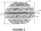
- the footprint 32 is the area that is created or formed as the tread 20 contacts the ground as the tire 12 rotates.
- the footprint 32 includes a width 34 that extends in a lateral direction across the tread 20.
- the footprint 32 also includes a centerline 36 that extends in a circumferential direction, that is, perpendicular to an axial or lateral direction.
- the centerline 36 is disposed at the middle of the width 34 of the footprint 32, and includes a length 38 that is referred to as the footprint centerline length or the footprint length.
- the footprint length 38 may be sensed by the tire-mounted sensor 26 ( Figure 1 ) or by another suitable sensor.
- the sensor 26 may include a strain sensor or piezoelectric sensor that measures deformation of the tread 20 and thus indicates the footprint length 38.
- the tire load estimation system 10 employs the measured footprint length 38 to estimate tire load.
- the system 10 provides a compensation or correction of the measured footprint length 38 to account for inflation pressure effects, while also compensating for a loading state by comparing a footprint length 38F of a front tire 12F to a footprint length 38R of a rear tire 12R.
- the system 10 also provides a compensation or correction of the footprint length 38 that accounts for wear of the tire 12.
- the tire-mounted sensor 26 preferably wirelessly transmits the measured footprint length 38 and a measured inflation pressure 40 of the tire 12 to the processor 28.
- a pressure correction module 42 is stored on or is in electronic communication with the processor 28 and receives the measured footprint length 38 and the measured inflation pressure 40 for each tire 12. The pressure correction module 42 provides a compensation or correction of the measured footprint length 38 to account for inflation pressure effects.
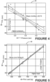
- a plot 44 of the footprint length 38 versus the inflation pressure 40 of the tire 12 shows how the inflation pressure of the tire affects the footprint length. Specifically, a higher inflation pressure 40 corresponds to a shorter footprint length 38. In order to remove the effect of inflation pressure 40 on footprint length 38 and thus normalize the footprint length, the pressure correction module 42 receives the measured footprint length and the measured inflation pressure.
- the pressure correction module 42 also compensates for a loading state 46 of the tire 12. More particularly, to accurately adjust the measured footprint length 38 for changes in inflation pressure 40, the loading state 46 of the tire 12 needs to be accounted for.
- a plot 48 of the footprint length 38 versus the loading state 46 for the tire 12 shows how the loading state of the tire affects the footprint length. Specifically, a higher loading state 46 corresponds to a longer footprint length 38.
- the load on a front vehicle tire 12F does not significantly change when the vehicle is fully laden.
- a footprint length 38F of the front tire 12F does not significantly change.
- the load on a rear vehicle tire 12R significantly changes when the vehicle 14 is fully laden, and a footprint length 38R of the rear tire significantly changes.
- the footprint length 38F of the front tire 12F may be used as a reference and compared to the footprint length 38R of the rear tire 12R to estimate the loading state of the vehicle 14, which may then be used to account for the loading state 46 of the tire 12.
- a plot 50 or comparison of the tire loading state 46 to a ratio 52 of the footprint length 38F of the front tire 12F to the footprint length 38R of the rear tire 12R under cruising conditions for the vehicle 14 shows that the vehicle loading state 54 may be determined. It is to be understood that a cruising condition is when the vehicle 14 is driven at a constant speed on a straight road.
- the vehicle loading state 54 may be categorized as empty 56, half laden 58, or fully laden 60.
- the determination of the vehicle loading state 54 preferably is made by a vehicle loading state estimator 62.
- the tire-mounted sensor 26 preferably wirelessly transmits the measured footprint length 38F and an inflation pressure 40F of a front tire 12F, and the measured footprint length 38R and an inflation pressure 40R of a rear tire 12R, to the processor 28.
- the vehicle loading state estimator 62 is stored on or is in electronic communication with the processor 28 and receives the measured footprint lengths 38F and 38R and the inflation pressures 40F and 40R.
- Each measured footprint length 38F and 38R is filtered to remove signal noise from the measured data with a de-noising module 64.
- a de-noising module 64 An example of a de-noising module 64 is described in greater detail below.
- the de-noising module 64 outputs a filtered front footprint length 66F for the front tire 12F and a filtered footprint length 66R for the rear tire 12R.
- a ratio estimator 68 compares the filtered front footprint length 66F to the filtered rear footprint length 66R to determine the footprint length ratio 52.
- the measured inflation pressure 40F for the front tire 12F, the measured inflation pressure 40R for the rear tire 12R, and the footprint length ratio 52 are input into a vehicle loading state estimation classification model 70 of the vehicle loading state estimator 62.
- the classification model 70 preferably identifies the vehicle loading state 54 from a multiclass classification of empty 56, half laden 58, or fully laden 60 using the front inflation pressure 40F, the rear inflation pressure 40R, and the footprint length ratio 52.
- the classifier 72 employs a multinomial logistic regression classification methodology, such as a softmax regression, to identify the vehicle loading state 54.
- the multinomial logistic regression classification methodology is preferred based on its capability to predict the probabilities of different outcomes of a categorically distributed dependent variable when given a set of independent variables.
- the vehicle loading state estimation classification model 70 determines the specific loading state 54 of the vehicle 14, which is described by way of example as empty 56, half laden 58, or fully laden 60.
- the loading state estimator 62 determines the loading state 54 of the vehicle 14, the loading state is correlated to an inflation sensitivity 72 for the tire 12.
- the inflation sensitivity may be stored in a lookup table or database 74 that is stored on or is in electronic communication with the processor 28.
- the inflation sensitivity 72 that corresponds to the specific loading state 54 enables a predetermined inflation correction factor 76 for the tire 12 to be determined.
- the inflation correction factor 76 is input into the pressure correction module 42 along with the measured footprint length 38 and the measured inflation pressure 40 for the tire 12.
- the pressure correction module 42 adjusts the measured footprint length 38 according to the measured inflation pressure 40 and the inflation correction factor 76, thereby accounting for changes in inflation pressure and the loading state of the tire, to determine an adjusted footprint length 78.
- the pressure correction module 42 preferably includes a regression model, which may be a linear regression model or a nonlinear regression model, to determine the adjusted footprint length 78.
- the relationship between the measured footprint length 38 and the measured inflation pressure 40 may be accomplished with a linear regression model, which may be based on data from testing of the vehicle 14.
- the adjusted footprint length 78 is filtered to remove signal noise from the measured data with a de-noising module 64, which is stored on or is in electronic communication with the processor 28.
- the de-noising module 64 may receive a steering wheel angle 80 of the vehicle 14 as an input from the vehicle CAN bus system 30.
- the steering wheel angle 80 is input into an event filter 82, which screens the measured footprint length data 38 to ensure that only footprint length measurements during straight-line travel of the vehicle 14 are analyzed. In this manner, the event filter 82 ensures that consistent footprint length measurements 38 from straight-line travel are employed.
- a de-noising algorithm 84 filters the adjusted footprint length data 78.
- a preferred de-noising algorithm 84 is an adaptive filter algorithm, such as a recursive least square algorithm with a forgetting factor, which gives less weight to older data samples to ensure that the most recent data receives a higher priority.
- the adjusted footprint length data 78 is smoothed in a smoothing module 86 to capture significant patterns in the data.
- the smoothing module 86 employs a technique that is useful for time series data such as the adjusted footprint length data 78.
- a preferred technique in the smoothing module 86 is an exponential weighted average filter.
- a filtered footprint length 88 for the tire 12 is yielded.
- the measured footprint length 38 and the filtered footprint length 88 typically decrease.
- the shortened footprint length may create an inaccurate presumption that the tire load is changing.
- the tire load estimation system 10 corrects for wear of the tire 12 with a wear correction model 90.
- the wear correction module 90 receives the filtered footprint length 88 and is stored on or is in electronic communication with the processor 28. It has been determined that wear appears as a slow-moving drift in the filtered footprint length data 88. The wear correction module 90 removes the drift in the filtered footprint length data 88 to correct for wear of the tire 12. To remove the drift, the wear correction module 90 applies a direct current (DC) block filter to the filtered footprint length data 88.
- the DC block filter separates the signal for the filtered footprint length data 88 into two components. The first component is a DC component, which carries a load dependency, and the second component is a drift component, which carries a wear dependency.
- the wear correction module 90 identifies and removes the drift component from the filtered footprint length data 88 to generate a wear-corrected footprint length 106.
- the wear-corrected footprint length 106 is input into a load determination model 92, which is stored on or is in electronic communication with the processor 28.
- the load determination model 92 preferably employs a regression model to calculate the load on the tire 12 that corresponds to the wear-corrected footprint length 106.
- the regression model may be a linear regression model, or a nonlinear regression model.
- the load determination model 92 thus determines and outputs an estimated load 94 on the tire 12.
- the estimated load 94 may be communicated through the vehicle CAN bus system 30 from the tire load estimation system 10 for use by a vehicle control system, such as a braking, traction, stability, and/or suspension system.
- the tire load estimation system 10 preferably is executed on a processor 28 that is accessible through the vehicle CAN bus 30, which may be mounted on the vehicle 14, or which may be in an Internet or cloud-based computing system 96, referred to herein as a cloud-based computing system.
- the tire load estimation system 10 preferably employs wireless data transmission 98 between the vehicle 14 and the cloud-based computing system 96.
- the tire load estimation system 10 may also employ wireless data transmission 100 between the cloud-based computing system 96 and a display device 102 that is accessible to a user of the vehicle 14, such as a smartphone, or to a fleet manager.
- the system 10 may also employ wireless data transmission 104 between the vehicle CAN bus 30 and the display device 102.
- the tire load estimation system 10 of the present invention indirectly estimates tire load in an accurate and reliable manner using the measured footprint length 38 of the tire 12.
- the tire load estimation system 10 provides compensation of the measured footprint length 38 to account for inflation pressure effects, and also compensates for a loading state by comparing a footprint length 38F of a front tire 12F to a footprint length 38R of a rear tire 12R.
- the system 10 also provides a compensation or correction of the footprint length 38 that accounts for wear of the tire 12.
- the present invention also includes a method for estimating the load of a tire 12.
- the method includes steps in accordance with the description that is presented above and shown in Figures 1 through 9 .
Landscapes
- Engineering & Computer Science (AREA)
- Mechanical Engineering (AREA)
- Physics & Mathematics (AREA)
- General Physics & Mathematics (AREA)
- Chemical & Material Sciences (AREA)
- Analytical Chemistry (AREA)
- Tires In General (AREA)
- Measuring Fluid Pressure (AREA)
Claims (15)
- Lastschätzungssystem für einen Luftreifen (12), wobei der Luftreifen (12) ein Paar Seitenwände (18) enthält, die sich zu einer Umfangslauffläche (20) erstrecken und ein Fahrzeug (14) tragen, wobei das System (10) das Folgende umfasst:einen Sensor (26), der an dem Reifen (12) angebracht und so konfiguriert ist, dass er einen Aufpumpdruck (40) des Reifens (12) misst;eine Aufstandsfläche (32), die durch die Lauffläche (20) gebildet wird, wobei die Aufstandsfläche (32) eine Länge der Aufstandsfläche (38) umfasst; wobei der Sensor (26) so konfiguriert ist, dass er die Länge (38) der Aufstandsfläche misst;einen Prozessor (28), der mit dem Sensor (26) elektronisch in Verbindung steht;eine Vorrichtung (62) zum Schätzen des Beladungszustands des Fahrzeugs, die mit dem Prozessor (28) elektronisch in Verbindung steht, um einen Beladungszustand (50) des Fahrzeugs (14) zu bestimmen;ein Modul zur Druckkorrektur (42), das elektronisch mit dem Prozessor (28) in Verbindung steht; wobei das Modul zur Druckkorrektur (42) so konfiguriert ist, dass es eine gemessene Länge der Aufstandsfläche (38), einen gemessenen Aufpumpdruck des Reifens (12) und einen aus dem Beladungszustand (54) des Fahrzeugs (14) ermittelten Aufpumpkorrekturfaktor (76) empfängt; wobei das Modul zur Druckkorrektur (42) so konfiguriert ist, dass es eine Länge der Aufstandsfläche (78) bestimmt, die angepasst wurde;ein Modul (64) zur Unterdrückung der Lärmbelästigungen, das mit dem Prozessor (28) elektronisch in Verbindung steht, wobei das Modul (64) zur Unterdrückung der Lärmbelästigungen so konfiguriert ist, dass es die angepasste Länge der Aufstandsfläche (78) empfängt, um eine gefilterte Länge der Aufstandsfläche (88) zu erzeugen;ein Modul zur Verschleißkorrektur (90), das elektronisch mit dem Prozessor (28) in Verbindung steht, wobei das Modul zur Verschleißkorrektur (90) so konfiguriert ist, dass es die Länge der Aufstandsfläche (88), die gefiltert wurde, empfängt und den Verschleiß des Reifens (12) korrigiert, um eine Länge der Aufstandsfläche (106) zu erzeugen, die hinsichtlich des Verschleißes korrigiert wurde; undein Modell zur Bestimmung der Belastung (92), das elektronisch mit dem Prozessor (28) in Verbindung steht, wobei das Modell zur Bestimmung der Belastung (92) so konfiguriert ist, dass es die Länge der Aufstandsfläche (106) empfängt, die hinsichtlich des Verschleißes korrigiert wurde, und eine geschätzte Last (94 ) hinsichtlich des Reifens (12) bestimmt.
- System nach Anspruch 1, wobei der Reifen (12) ein Vorderreifen ist, der Sensor (28) einen Sensor an der Vorderseite darstellt, der in dem Vorderreifen angebracht ist, der Aufpumpdruck einen Aufpumpdruck an der Vorderseite darstellt; und die Länge der Aufstandsfläche eine Länge der Aufstandsfläche an der Vorderseite darstellt, wobei das System (10) ferner das Folgende umfasst:einen hinteren Luftreifen;einen hinteren Sensor, der an dem hinteren Reifen angebracht ist und so konfiguriert ist, dass er einen hinteren Reifendruck des hinteren Reifens misst;eine hintere Aufstandsfläche, die durch eine Lauffläche des hinteren Reifens gebildet wird, wobei die hintere Aufstandsfläche eine Länge der hintere Aufstandsfläche enthält;wobei der hintere Sensor so konfiguriert ist, dass er die Länge der hinteren Aufstandsfläche misst;und wobei die Vorrichtung (62) zum Schätzen des Beladungszustands des Fahrzeugs so konfiguriert ist, dass sie die gemessenen vorderen und hinteren Längen der Aufstandsflächen sowie die vorderen und hinteren Reifendrücke empfängt.
- System nach Anspruch 1 oder 2, wobei die Vorrichtung (62) zum Schätzen des Ladezustands des Fahrzeugs ein Modul (64) zur Unterdrückung der Lärmbelästigungen umfasst, das so konfiguriert ist, dass es die gemessene vordere Länge der Aufstandsfläche und/oder die gemessene hintere Länge der Aufstandsfläche empfängt, wobei das Modul (64) zur Unterdrückung der Lärmbelästigungen so konfiguriert ist, dass es das Signalrauschen entfernt, um eine vordere gefilterte Länge der Aufstandsfläche und/oder eine hintere gefilterte Länge der Aufstandsfläche zu erzeugen.
- System nach Anspruch 3, wobei die Vorrichtung (62) zum Schätzen des Beladungszustands des Fahrzeugs eine Vorrichtung (68) zum Bestimmen eines Verhältnisses enthält, die so konfiguriert ist, dass sie die vordere gefilterte Länge der Aufstandsfläche mit der hinteren gefilterten Länge der Aufstandsfläche vergleicht, um ein Verhältnis der Längen der Aufstandsflächen (52) zu bestimmen.
- System nach Anspruch 4, wobei die Vorrichtung (62) zum Schätzen des Beladungszustands des Fahrzeugs ein Modell (70) zur Klassifizierung der Schätzung des Ladezustands des Fahrzeugs umfasst, wobei das Modell (70) zur Klassifizierung der Schätzung des Ladezustands des Fahrzeugs so konfiguriert ist, dass es den vorderen Reifendruck, den hinteren Reifendruck und das Verhältnis der Längen der Aufstandsflächen empfängt, um den Ladezustand des Fahrzeugs zu bestimmen.
- System nach Anspruch 5, wobei das Modell (70) zur Klassifizierung der Schätzung des Ladezustands des Fahrzeugs so konfiguriert ist, dass es eine Klassifizierungsmethodik verwendet, die auf einer multinomialen logistischen Regression basiert; und/oder wobei der Ladezustand (54) des Fahrzeugs (14) eine Klassifizierung umfasst, die mindestens eine Klasse umfasst, die ausgewählt ist aus: leer (56), halb beladen (58) und voll beladen (60).
- System nach mindestens einem der vorhergehenden Ansprüche, wobei das System (10) weiterhin das Folgende umfasst:mindestens ein Element, ausgewählt aus einer Nachschlagetabelle (74) und einer Datenbank, die mit dem Prozessor (28) in Verbindung steht; undeine Aufpumpempfindlichkeit (72), die in dem mindestens einen Element gespeichert ist, das aus der Nachschlagetabelle (74) und der Datenbank ausgewählt ist, wobei die Aufpumpempfindlichkeit (72) mit einer Klassifizierung des Ladezustands des Fahrzeugs korreliert ist; und, optional, wobei das System (10) so konfiguriert ist, dass es den Aufpumpkorrekturfaktor (76) aus der Aufpumpempfindlichkeit bestimmt.
- System nach mindestens einem der vorhergehenden Ansprüche, wobei das Modul (64) zur Unterdrückung der Lärmbelästigungen einen Ereignisfilter (82) umfasst, wobei der Ereignisfilter (82) so konfiguriert ist, dass er einen Lenkradwinkel des Fahrzeugs (14) empfängt, der von einem Kontrollnetz-bus (30) des Fahrzeugs (14) ausgegeben wird, vorzugsweise, um sicherzustellen, dass nur Längen der Aufstandsflächen während einer Geradeausfahrt des Fahrzeugs (14) analysiert werden.
- System nach mindestens einem der vorhergehenden Ansprüche, wobei das Modul (64) zur Unterdrückung der Lärmbelästigungen einen Lärmbelästigungsalgorithmus enthält, um die Daten der Länge der Aufstandsfläche, die angepasst wurden, zu filtern, wobei der Lärmbelästigungsalgorithmus ein Algorithmus der rekursive kleinste Quadrate enthält, der einen Vergessensfaktor umfasst.
- System nach mindestens einem der vorhergehenden Ansprüche, wobei das Modul (64) zur Unterdrückung der Lärmbelästigungen ein Glättungsmodul (86) enthält, wobei das Glättungsmodul (86) vorzugsweise so konfiguriert ist, dass es die angepasste Länge der Aufstandsfläche aus dem Algorithmus zur Unterdrückung von Lärmbelästigungen empfängt, um die gefilterte Länge der Aufstandsfläche zu erzeugen, und/oder wobei das Glättungsmodul (86) vorzugsweise so konfiguriert ist, dass es einen Filter auf Basis des exponentiell gewichteten Durchschnitts verwendet.
- System nach mindestens einem der vorhergehenden Ansprüche, wobei das Modul zur Verschleißkorrektur (90) einen Gleichstromsperrfilter umfasst, wobei der Gleichstromsperrfilter so konfiguriert ist, dass er ein Signal für die gefilterte Länge der Aufstandsfläche in eine Gleichstromkomponente, die eine Lastabhängigkeit trägt, und eine Driftkomponente, die eine Verschleißabhängigkeit trägt, trennt; und/oder wobei das Modul zur Verschleißkorrektur (90) so konfiguriert ist, dass es die Driftkomponente aus der Länge der Aufstandsfläche, die gefiltert wurde, entfernt, um die Länge der Aufstandsfläche zu erzeugen, die hinsichtlich des Verschleißes korrigiert wurde.
- System nach mindestens einem der vorhergehenden Ansprüche, wobei das Modell zur Bestimmung der Belastung (92) so konfiguriert ist, dass es ein Regressionsmodell verwendet, vorzugsweise ein lineares Regressionsmodell.
- System nach mindestens einem der vorhergehenden Ansprüche, das ferner ein Fahrzeugregelsystem umfasst, das mit dem Prozessor (28) elektronisch in Verbindung steht, wobei das Fahrzeugregelsystem so konfiguriert ist, dass es die geschätzte Last (94) auf dem Luftreifen empfängt.
- System nach mindestens einem der vorhergehenden Ansprüche, wobei der Prozessor (28) mindestens einer von einem Prozessor, der an Bord des Fahrzeugs montiert ist, und einem Prozessor in einem cloudbasierten Computersystem ist oder einen von diesen enthält.
- Verfahren zur Schätzung der Last eines Luftreifens (12), wobei der Luftreifen (12) ein Paar Seitenwände (18) enthält, die sich zu einer Umfangslauffläche (20) erstrecken und ein Fahrzeug (14) tragen, wobei das Verfahren folgende Schritte umfasst:das Anbringen eines Sensors (26) an den Reifen (12);das Messen eines Aufpumpdrucks (40) des Reifens (12) mit dem Sensor (26);das Messen, mit dem Sensor (26), einer Länge einer Aufstandsfläche (32), die durch die Lauffläche (20) gebildet wird;das Bereitstellen eines Prozessors (28), der mit dem Sensor (26) elektronisch in Verbindung steht;das Bestimmen eines Beladungszustands (54) des Fahrzeugs (14) mit einer Vorrichtung (62) zum Schätzen des Beladungszustands des Fahrzeugs, die mit dem Prozessor (28) elektronisch in Verbindung steht;das Bestimmen eines Aufpumpkorrekturfaktors (76) aus dem Beladungszustand (54) des Fahrzeugs (14);das Bestimmen einer angepassten Länge der Aufstandsfläche (78) mit einem Modul zur Druckkorrektur (42), das elektronisch mit dem Prozessor (28) in Verbindung steht; wobei das Modul zur Druckkorrektur (42) die gemessene Länge der Aufstandsfläche (38), den gemessenen Aufpumpdruck des Reifens (12) und den Aufpumpkorrekturfaktor (76) empfängt;das Erzeugen einer gefilterten Länge der Aufstandsfläche (88) mit einem Modul (64) zur Unterdrückung der Lärmbelästigungen, das mit dem Prozessor (28) elektronisch in Verbindung steht, wobei das Modul (64) zur Unterdrückung der Lärmbelästigungen die angepasste Länge der Aufstandsfläche (78) empfängt;das Erzeugen einer Länge der Aufstandsfläche (106), deren Verschleiß korrigiert wurde, mit einem Modul zur Verschleißkorrektur (90), das elektronisch mit dem Prozessor (28) in Verbindung steht, wobei das Modul zur Verschleißkorrektur (90) die gefilterte Länge der Aufstandsfläche (88) empfängt; unddas Bestimmen einer geschätzten Last (94) hinsichtlich des Reifens (12) mit einem Modell zur Bestimmung der Belastung (92), das elektronisch mit dem Prozessor (28) in Verbindung steht, wobei das Modell zur Bestimmung der Belastung (92) die Länge der Aufstandsfläche (106) empfängt, die hinsichtlich des Verschleißes korrigiert wurde.
Applications Claiming Priority (2)
| Application Number | Priority Date | Filing Date | Title |
|---|---|---|---|
| US202163238266P | 2021-08-30 | 2021-08-30 | |
| US17/818,837 US20230060281A1 (en) | 2021-08-30 | 2022-08-10 | Load estimation system for a tire |
Publications (2)
| Publication Number | Publication Date |
|---|---|
| EP4140777A1 EP4140777A1 (de) | 2023-03-01 |
| EP4140777B1 true EP4140777B1 (de) | 2025-01-01 |
Family
ID=83050090
Family Applications (1)
| Application Number | Title | Priority Date | Filing Date |
|---|---|---|---|
| EP22191779.2A Active EP4140777B1 (de) | 2021-08-30 | 2022-08-23 | System und verfahren zur schätzung der reifenlast |
Country Status (2)
| Country | Link |
|---|---|
| US (1) | US20230060281A1 (de) |
| EP (1) | EP4140777B1 (de) |
Families Citing this family (3)
| Publication number | Priority date | Publication date | Assignee | Title |
|---|---|---|---|---|
| US12589618B2 (en) | 2022-11-11 | 2026-03-31 | The Goodyear Tire & Rubber Company | Method and system for monitoring tire inflation pressure |
| US20260001558A1 (en) | 2024-06-26 | 2026-01-01 | The Goodyear Tire & Rubber Company | Hydroplaning detection system |
| CN119026254B (zh) * | 2024-10-31 | 2025-02-14 | 清华大学苏州汽车研究院(相城) | 估计模型的生成方法、车辆载重的估计方法及其装置 |
Family Cites Families (10)
| Publication number | Priority date | Publication date | Assignee | Title |
|---|---|---|---|---|
| US7197422B2 (en) * | 2005-08-11 | 2007-03-27 | Gm Global Technology Operations, Inc. | System and method for determining proper tire inflation pressure based on current vehicle mass conditions |
| DE102005060857A1 (de) * | 2005-12-20 | 2007-06-28 | Robert Bosch Gmbh | Verfahren zur Plausibilisierung einer ermittelten Fahrzeugmasse |
| DE102006043505A1 (de) * | 2006-05-22 | 2007-11-29 | Continental Teves Ag & Co. Ohg | Reifenmodul und Verfahren zur Erfassung von Rad- und/oder Reifenzustandsgrößen |
| US10245906B2 (en) * | 2014-11-11 | 2019-04-02 | The Goodyear Tire & Rubber Company | Tire wear compensated load estimation system and method |
| GB2533658A (en) * | 2014-12-22 | 2016-06-29 | Continental Automotive Gmbh | Method and system for determining a wheel load acting on a tire of a vehicle |
| DE102017208213A1 (de) * | 2017-05-16 | 2018-11-22 | Bayerische Motoren Werke Aktiengesellschaft | Reifendruckregelsystem eines Fahrzeugs |
| US11001103B2 (en) * | 2018-01-31 | 2021-05-11 | The Goodyear Tire & Rubber Company | Tread for a tire |
| US11298991B2 (en) * | 2018-11-28 | 2022-04-12 | The Goodyear Tire & Rubber Company | Tire load estimation system and method |
| US11981163B2 (en) * | 2019-08-30 | 2024-05-14 | The Goodyear Tire & Rubber Company | Tire wear state estimation system and method employing footprint shape factor |
| KR20210045571A (ko) * | 2019-10-16 | 2021-04-27 | 현대자동차주식회사 | 차량 정보 모니터링 장치 및 방법 |
-
2022
- 2022-08-10 US US17/818,837 patent/US20230060281A1/en active Pending
- 2022-08-23 EP EP22191779.2A patent/EP4140777B1/de active Active
Also Published As
| Publication number | Publication date |
|---|---|
| EP4140777A1 (de) | 2023-03-01 |
| US20230060281A1 (en) | 2023-03-02 |
Similar Documents
| Publication | Publication Date | Title |
|---|---|---|
| EP3659831B1 (de) | System und verfahren zur reifenlastschätzung | |
| EP4140777B1 (de) | System und verfahren zur schätzung der reifenlast | |
| EP3838628B1 (de) | Verfahren zur festsellung von reifenzuständen | |
| US11548324B2 (en) | Tire wear state estimation system and method employing footprint length | |
| EP1675735B1 (de) | Verfahren und system zur feststellung von der reifenladung während der fahrt eines fahrzeuges | |
| US9739689B2 (en) | Tire cornering stiffness estimation system and method | |
| US20140257629A1 (en) | Tire load estimation system using road profile adaptive filtering | |
| EP3785944B1 (de) | System und verfahren zur schätzung des verschleisszustandes eines reifens unter verwendung des formfaktors der aufstandsfläche | |
| US12115821B2 (en) | Tire pressure monitoring system employing axle cross comparison | |
| AU2020286203A1 (en) | Method of estimating tire conditions | |
| US12263704B2 (en) | Tire irregular wear detection system and method | |
| CN112440629A (zh) | 用于提取轮胎特性的变化的方法 | |
| CN115923409B (zh) | 用于轮胎的载荷估计系统 | |
| EP4140783B1 (de) | Reifendrucküberwachungssystem und -verfahren | |
| EP4385762B1 (de) | System und verfahren zur schätzung der reifenlaufflächentiefe unter verwendung der raddrehzahl | |
| EP4140838B1 (de) | Strassenzustandsüberwachungssystem und -verfahren | |
| EP4725717A1 (de) | Vorrichtung zur schätzung des reifenverschleisses und verfahren zur schätzung des verschleisses | |
| EP4151436B1 (de) | System und verfahren zur schätzung der gegenablenkungslast | |
| CN115723765A (zh) | 道路状况监测系统 | |
| CN115782473B (zh) | 用于轮胎的反向挠度载荷估计系统 | |
| CN118182021A (zh) | 利用印迹长度自动定位轮胎的系统 |
Legal Events
| Date | Code | Title | Description |
|---|---|---|---|
| PUAI | Public reference made under article 153(3) epc to a published international application that has entered the european phase |
Free format text: ORIGINAL CODE: 0009012 |
|
| STAA | Information on the status of an ep patent application or granted ep patent |
Free format text: STATUS: THE APPLICATION HAS BEEN PUBLISHED |
|
| AK | Designated contracting states |
Kind code of ref document: A1 Designated state(s): AL AT BE BG CH CY CZ DE DK EE ES FI FR GB GR HR HU IE IS IT LI LT LU LV MC MK MT NL NO PL PT RO RS SE SI SK SM TR |
|
| STAA | Information on the status of an ep patent application or granted ep patent |
Free format text: STATUS: REQUEST FOR EXAMINATION WAS MADE |
|
| 17P | Request for examination filed |
Effective date: 20230901 |
|
| RBV | Designated contracting states (corrected) |
Designated state(s): AL AT BE BG CH CY CZ DE DK EE ES FI FR GB GR HR HU IE IS IT LI LT LU LV MC MK MT NL NO PL PT RO RS SE SI SK SM TR |
|
| GRAP | Despatch of communication of intention to grant a patent |
Free format text: ORIGINAL CODE: EPIDOSNIGR1 |
|
| STAA | Information on the status of an ep patent application or granted ep patent |
Free format text: STATUS: GRANT OF PATENT IS INTENDED |
|
| INTG | Intention to grant announced |
Effective date: 20240731 |
|
| GRAS | Grant fee paid |
Free format text: ORIGINAL CODE: EPIDOSNIGR3 |
|
| GRAA | (expected) grant |
Free format text: ORIGINAL CODE: 0009210 |
|
| STAA | Information on the status of an ep patent application or granted ep patent |
Free format text: STATUS: THE PATENT HAS BEEN GRANTED |
|
| AK | Designated contracting states |
Kind code of ref document: B1 Designated state(s): AL AT BE BG CH CY CZ DE DK EE ES FI FR GB GR HR HU IE IS IT LI LT LU LV MC MK MT NL NO PL PT RO RS SE SI SK SM TR |
|
| REG | Reference to a national code |
Ref country code: GB Ref legal event code: FG4D |
|
| REG | Reference to a national code |
Ref country code: CH Ref legal event code: EP |
|
| REG | Reference to a national code |
Ref country code: DE Ref legal event code: R096 Ref document number: 602022009270 Country of ref document: DE |
|
| REG | Reference to a national code |
Ref country code: IE Ref legal event code: FG4D |
|
| REG | Reference to a national code |
Ref country code: LT Ref legal event code: MG9D |
|
| REG | Reference to a national code |
Ref country code: NL Ref legal event code: MP Effective date: 20250101 |
|
| REG | Reference to a national code |
Ref country code: AT Ref legal event code: MK05 Ref document number: 1755888 Country of ref document: AT Kind code of ref document: T Effective date: 20250101 |
|
| PG25 | Lapsed in a contracting state [announced via postgrant information from national office to epo] |
Ref country code: NL Free format text: LAPSE BECAUSE OF FAILURE TO SUBMIT A TRANSLATION OF THE DESCRIPTION OR TO PAY THE FEE WITHIN THE PRESCRIBED TIME-LIMIT Effective date: 20250101 |
|
| PG25 | Lapsed in a contracting state [announced via postgrant information from national office to epo] |
Ref country code: FI Free format text: LAPSE BECAUSE OF FAILURE TO SUBMIT A TRANSLATION OF THE DESCRIPTION OR TO PAY THE FEE WITHIN THE PRESCRIBED TIME-LIMIT Effective date: 20250101 |
|
| PG25 | Lapsed in a contracting state [announced via postgrant information from national office to epo] |
Ref country code: PL Free format text: LAPSE BECAUSE OF FAILURE TO SUBMIT A TRANSLATION OF THE DESCRIPTION OR TO PAY THE FEE WITHIN THE PRESCRIBED TIME-LIMIT Effective date: 20250101 |
|
| PG25 | Lapsed in a contracting state [announced via postgrant information from national office to epo] |
Ref country code: ES Free format text: LAPSE BECAUSE OF FAILURE TO SUBMIT A TRANSLATION OF THE DESCRIPTION OR TO PAY THE FEE WITHIN THE PRESCRIBED TIME-LIMIT Effective date: 20250101 |
|
| PG25 | Lapsed in a contracting state [announced via postgrant information from national office to epo] |
Ref country code: NO Free format text: LAPSE BECAUSE OF FAILURE TO SUBMIT A TRANSLATION OF THE DESCRIPTION OR TO PAY THE FEE WITHIN THE PRESCRIBED TIME-LIMIT Effective date: 20250401 Ref country code: IS Free format text: LAPSE BECAUSE OF FAILURE TO SUBMIT A TRANSLATION OF THE DESCRIPTION OR TO PAY THE FEE WITHIN THE PRESCRIBED TIME-LIMIT Effective date: 20250501 |
|
| PG25 | Lapsed in a contracting state [announced via postgrant information from national office to epo] |
Ref country code: HR Free format text: LAPSE BECAUSE OF FAILURE TO SUBMIT A TRANSLATION OF THE DESCRIPTION OR TO PAY THE FEE WITHIN THE PRESCRIBED TIME-LIMIT Effective date: 20250101 |
|
| PG25 | Lapsed in a contracting state [announced via postgrant information from national office to epo] |
Ref country code: PT Free format text: LAPSE BECAUSE OF FAILURE TO SUBMIT A TRANSLATION OF THE DESCRIPTION OR TO PAY THE FEE WITHIN THE PRESCRIBED TIME-LIMIT Effective date: 20250502 Ref country code: LV Free format text: LAPSE BECAUSE OF FAILURE TO SUBMIT A TRANSLATION OF THE DESCRIPTION OR TO PAY THE FEE WITHIN THE PRESCRIBED TIME-LIMIT Effective date: 20250101 |
|
| PG25 | Lapsed in a contracting state [announced via postgrant information from national office to epo] |
Ref country code: BG Free format text: LAPSE BECAUSE OF FAILURE TO SUBMIT A TRANSLATION OF THE DESCRIPTION OR TO PAY THE FEE WITHIN THE PRESCRIBED TIME-LIMIT Effective date: 20250101 Ref country code: GR Free format text: LAPSE BECAUSE OF FAILURE TO SUBMIT A TRANSLATION OF THE DESCRIPTION OR TO PAY THE FEE WITHIN THE PRESCRIBED TIME-LIMIT Effective date: 20250402 |
|
| PG25 | Lapsed in a contracting state [announced via postgrant information from national office to epo] |
Ref country code: AT Free format text: LAPSE BECAUSE OF FAILURE TO SUBMIT A TRANSLATION OF THE DESCRIPTION OR TO PAY THE FEE WITHIN THE PRESCRIBED TIME-LIMIT Effective date: 20250101 |
|
| PG25 | Lapsed in a contracting state [announced via postgrant information from national office to epo] |
Ref country code: CZ Free format text: LAPSE BECAUSE OF FAILURE TO SUBMIT A TRANSLATION OF THE DESCRIPTION OR TO PAY THE FEE WITHIN THE PRESCRIBED TIME-LIMIT Effective date: 20250101 |
|
| PG25 | Lapsed in a contracting state [announced via postgrant information from national office to epo] |
Ref country code: SE Free format text: LAPSE BECAUSE OF FAILURE TO SUBMIT A TRANSLATION OF THE DESCRIPTION OR TO PAY THE FEE WITHIN THE PRESCRIBED TIME-LIMIT Effective date: 20250101 |
|
| REG | Reference to a national code |
Ref country code: DE Ref legal event code: R097 Ref document number: 602022009270 Country of ref document: DE |
|
| PG25 | Lapsed in a contracting state [announced via postgrant information from national office to epo] |
Ref country code: SM Free format text: LAPSE BECAUSE OF FAILURE TO SUBMIT A TRANSLATION OF THE DESCRIPTION OR TO PAY THE FEE WITHIN THE PRESCRIBED TIME-LIMIT Effective date: 20250101 |
|
| PG25 | Lapsed in a contracting state [announced via postgrant information from national office to epo] |
Ref country code: DK Free format text: LAPSE BECAUSE OF FAILURE TO SUBMIT A TRANSLATION OF THE DESCRIPTION OR TO PAY THE FEE WITHIN THE PRESCRIBED TIME-LIMIT Effective date: 20250101 |
|
| PGFP | Annual fee paid to national office [announced via postgrant information from national office to epo] |
Ref country code: DE Payment date: 20250724 Year of fee payment: 4 |
|
| PGFP | Annual fee paid to national office [announced via postgrant information from national office to epo] |
Ref country code: IT Payment date: 20250901 Year of fee payment: 4 |
|
| PGFP | Annual fee paid to national office [announced via postgrant information from national office to epo] |
Ref country code: FR Payment date: 20250725 Year of fee payment: 4 |
|
| PG25 | Lapsed in a contracting state [announced via postgrant information from national office to epo] |
Ref country code: EE Free format text: LAPSE BECAUSE OF FAILURE TO SUBMIT A TRANSLATION OF THE DESCRIPTION OR TO PAY THE FEE WITHIN THE PRESCRIBED TIME-LIMIT Effective date: 20250101 |
|
| PG25 | Lapsed in a contracting state [announced via postgrant information from national office to epo] |
Ref country code: RO Free format text: LAPSE BECAUSE OF FAILURE TO SUBMIT A TRANSLATION OF THE DESCRIPTION OR TO PAY THE FEE WITHIN THE PRESCRIBED TIME-LIMIT Effective date: 20250101 |
|
| PG25 | Lapsed in a contracting state [announced via postgrant information from national office to epo] |
Ref country code: SK Free format text: LAPSE BECAUSE OF FAILURE TO SUBMIT A TRANSLATION OF THE DESCRIPTION OR TO PAY THE FEE WITHIN THE PRESCRIBED TIME-LIMIT Effective date: 20250101 |
|
| PLBE | No opposition filed within time limit |
Free format text: ORIGINAL CODE: 0009261 |
|
| STAA | Information on the status of an ep patent application or granted ep patent |
Free format text: STATUS: NO OPPOSITION FILED WITHIN TIME LIMIT |
|
| REG | Reference to a national code |
Ref country code: CH Ref legal event code: L10 Free format text: ST27 STATUS EVENT CODE: U-0-0-L10-L00 (AS PROVIDED BY THE NATIONAL OFFICE) Effective date: 20251112 |
|
| 26N | No opposition filed |
Effective date: 20251002 |
|
| REG | Reference to a national code |
Ref country code: CH Ref legal event code: H13 Free format text: ST27 STATUS EVENT CODE: U-0-0-H10-H13 (AS PROVIDED BY THE NATIONAL OFFICE) Effective date: 20260324 |
|
| PG25 | Lapsed in a contracting state [announced via postgrant information from national office to epo] |
Ref country code: MC Free format text: LAPSE BECAUSE OF FAILURE TO SUBMIT A TRANSLATION OF THE DESCRIPTION OR TO PAY THE FEE WITHIN THE PRESCRIBED TIME-LIMIT Effective date: 20250101 |
|
| PG25 | Lapsed in a contracting state [announced via postgrant information from national office to epo] |
Ref country code: LU Free format text: LAPSE BECAUSE OF NON-PAYMENT OF DUE FEES Effective date: 20250823 |
|
| PG25 | Lapsed in a contracting state [announced via postgrant information from national office to epo] |
Ref country code: CH Free format text: LAPSE BECAUSE OF NON-PAYMENT OF DUE FEES Effective date: 20250831 |