EP4140880B1 - Ensemble train d'atterrissage d'aéronef - Google Patents
Ensemble train d'atterrissage d'aéronef Download PDFInfo
- Publication number
- EP4140880B1 EP4140880B1 EP21194061.4A EP21194061A EP4140880B1 EP 4140880 B1 EP4140880 B1 EP 4140880B1 EP 21194061 A EP21194061 A EP 21194061A EP 4140880 B1 EP4140880 B1 EP 4140880B1
- Authority
- EP
- European Patent Office
- Prior art keywords
- arm
- landing gear
- pivot point
- pivotally coupled
- control link
- Prior art date
- Legal status (The legal status is an assumption and is not a legal conclusion. Google has not performed a legal analysis and makes no representation as to the accuracy of the status listed.)
- Active
Links
Images




Classifications
-
- B—PERFORMING OPERATIONS; TRANSPORTING
- B64—AIRCRAFT; AVIATION; COSMONAUTICS
- B64C—AEROPLANES; HELICOPTERS
- B64C25/00—Alighting gear
- B64C25/02—Undercarriages
- B64C25/08—Undercarriages non-fixed, e.g. jettisonable
- B64C25/10—Undercarriages non-fixed, e.g. jettisonable retractable, foldable, or the like
-
- B—PERFORMING OPERATIONS; TRANSPORTING
- B64—AIRCRAFT; AVIATION; COSMONAUTICS
- B64C—AEROPLANES; HELICOPTERS
- B64C25/00—Alighting gear
- B64C25/02—Undercarriages
- B64C25/08—Undercarriages non-fixed, e.g. jettisonable
- B64C25/10—Undercarriages non-fixed, e.g. jettisonable retractable, foldable, or the like
- B64C25/12—Undercarriages non-fixed, e.g. jettisonable retractable, foldable, or the like sideways
Definitions
- An aircraft landing gear assembly is generally movable between a deployed condition, for take-off and landing, and a stowed condition for flight.
- a stay assembly generally includes a stay and a lock link arranged to maintain the stay in a condition which corresponds to the landing gear assembly being in the deployed condition.
- the lock link is 'broken' and folded to enable the stay to be folded, permitting the main strut to be moved by a retraction actuator towards the stowed condition.
- landing gear assemblies It is common for landing gear assemblies to be arranged to move towards the deployed condition in the event of a failure of the retraction actuator. Initially the assembly will move by way of gravity and in doing so the landing gear assembly forces the stay to move towards the condition which corresponds to the landing gear assembly being in the deployed condition.
- One or more 'down-lock' springs may be provided to assist in moving landing gear assembly to the deployed condition and locking it in that state by biasing the lock link to lock.
- Landing gear assemblies for larger aircraft may be provided with a pair of down-lock springs on each stay assembly.
- US 2018/065733 A1 discloses a landing gear lock assembly includes a first lock link, and a second lock link, a first end of the second lock link being rotatably coupled to the second end of the first lock link so that the first and second lock links unfold relative to each other in a first rotation direction.
- EP1988015 discloses a landing gear assembly, with locking means using a spring.
- an aircraft landing gear assembly includes a linkage assembly which builds lost motion into the down-lock spring mounting mechanism.
- the control link moves over centre such that, in contrast to known landing gear assemblies, the down-lock spring does not continue to extend as the gear is retracted, thereby enabling a smaller and/or lighter down-lock spring to be provided.
- the linkage assembly can be arranged such that, as the structural members move from the first angular condition to the second angular condition, the spring extension is increased or magnified in comparison to a direct connection arrangement for a first portion of the movement and/or is reduced in comparison to a direct connection arrangement for a second portion of the movement.
- the second portion of the movement can start within the first half of the total movement of the landing gear from the fully deployed to the fully stowed condition.
- the magnification can be by at least a factor of 1.2 and preferably at least a factor of 1.3, 1.5 or 2, which can particularly assist the spring in locking the gear in the deployed condition as it nears the deployed condition.
- the magnification factor can refer to a maximum value.
- the degree of magnification can vary throughout the first portion of the movement.
- the variation can be in accordance with the angle of the structural member (to which the arm member is pivotally coupled) relative its orientation when in the first angular condition, in which the landing gear is in the deployed condition.
- the first portion of the movement can comprise less than 15 degrees of movement of the structural member (to which the arm member is pivotally coupled) relative its orientation when in the first angular condition. In one embodiment the first portion can comprise 0 to 10 degrees.
- the reduction can be by at least a factor of 2 and preferably at least a factor of 3 or 4. This can reduce maximum spring extension during retraction of the gear, enabling the use of lighter and/or smaller down-lock springs.
- the reduction factor can refer to a maximum value.
- the reduction factor can result in the spring being shorter at some point during retraction than when the gear is in the deployed condition, preferably when the gear is in the stowed condition.
- the second portion of the movement can start at 10 or more degrees of movement of the structural member (to which the arm member is pivotally coupled) relative its orientation when in the first angular condition and can extend to 70 degrees or more.
- the first angular condition can be an aligned condition, in which longitudinal axes of the first and second structural members are generally aligned with one another
- the second angular condition can be a non-aligned condition in which the longitudinal axes of the first and second structural members are generally not aligned with one another.
- the spring acts across the folding joint of a stay or lock link for example.
- the arm member can be longitudinally nonlinear.
- the arm member can be longitudinally C shaped.
- the arm member can comprise a plurality of linear portions rigidly coupled to form the longitudinal C shape.
- the arm member can be pivotally coupled to the second structural member, the arm pivot point being at a first end region of the arm and the control link being pivotally coupled to the first structural member.
- the second control link pivot point can be located on the arm at a location which is closer to the arm pivot point than the point via which the arm is pivotally coupled to the spring.
- the arm pivot point can be at a central region of the arm.
- the arm member can be pivotally coupled to the first structural member, the control link being pivotally coupled to the second structural member and the second control link pivot point being located at a second end region of the arm opposite to the first end region which is pivotally coupled to the down-lock spring.
- the arm member can be pivotally coupled to the first structural member, the control link being pivotally coupled to the second structural member and the linkage assembly further comprising a second C shaped arm pivotally coupled to the second structural member at a second arm pivot point located at a central region of the second arm, the second control link pivot point being located at a first end region of the second arm, the linkage assembly further comprising a second control link pivotally coupled to one of the first and second structural members at a first control link pivot point and pivotally coupled to a second end of the second arm at a third control link pivot point and pivotally coupled to a second end of the C shaped arm at a fourth control link pivot point such that, as the first and second structural members move relative to one another from the aligned condition towards the non-aligned condition, the first control link pivot point moves over centre, though an axis or plane bisecting the apex pivot point and the second control link pivot point and the third control link pivot point moves over centre, though an axis or plane bisecting the arm pivot point and
- the aircraft landing gear assembly can further comprise:
- the down-lock spring can be helical in shape.
- an aircraft including one or more aircraft landing gear assemblies according to the first aspect.
- FIG. 2a to 2e an aircraft assembly, namely an aircraft landing gear assembly, is shown generally at 14.
- Figures 2a to 2e are an example of an aircraft landing gear assembly which can include a shock absorber strut according to an embodiment of the invention. It will however be appreciated that shock absorber struts according to embodiments of the invention can be used in a range of types of aircraft landing gear.
- the landing gear assembly 14 includes a foldable stay 18, a lock link 20 and a down-lock spring assembly 22 mounted to the stay 18 and arranged to urge the lock link 20 to assume a locked state.
- the landing gear assembly also includes a main shock absorber strut 24, comprising an outer cylinder 26 and an inner cylinder 28, as well as a wheel and brake assembly 30.
- the aircraft landing gear assembly is movable between a deployed condition, for take-off and landing, and a stowed condition for flight.
- An actuator (not shown) is provided for moving the landing gear between the deployed condition and the stowed condition.
- This actuator is known in the art as a retraction actuator, and more than one can be provided.
- a retraction actuator can have one end coupled to the airframe and another end coupled to the outer cylinder such that extension and retraction of the actuator results in movement of the outer cylinder between deployed and stowed conditions.
- the stay 18 serves to support the orientation of the outer cylinder 26 when the landing gear is in the deployed condition.
- the stay 18 generally includes a two bar linkage that can be unfolded to assume a generally straight or aligned, over centre condition in which the stay 18 is locked to inhibit movement of the outer cylinder, as shown in Figures 2c and 2e .
- the stay When the stay is broken, it no longer prevents pivotal movement of the outer cylinder 26 and the outer cylinder 26 can be moved by the retraction actuator towards the stowed condition, as shown in Figure 2a .
- the stay 18 is arranged in the folded condition, while during take-off and landing the stay 18 is arranged in the generally straight or aligned condition.
- Some main landing gear assemblies include a pair of stays coupled to a common shock absorber strut.
- the stay 18 has an elongate upper stay arm 18a having a lower end defining a pair of lugs pivotally coupled via a pivot pin 32 to a pair of lugs defined at an upper end of an elongate lower stay arm 18b.
- the stay arms 18a and 18b can therefore pivotally move relative to one another about the pivot pin 32.
- the upper end of the upper stay arm 18a defines a pair of lugs that are pivotally coupled to a lug of a connector 34 which in turn is pivotally coupled to the airframe 11.
- the lower end of the lower stay arm 18b defines a pair of lugs pivotally coupled to a lug of a connector 36 which in turn is pivotally coupled to the outer cylinder 26.
- the lock link 20 has an elongate upper link arm 20a having a lower end pivotally coupled to an upper end of an elongate lower link arm 20b via a pivot pin 38.
- the link arms 20a, 20b can therefore pivotally move relative to one another about the pivot pin 38.
- An upper end of the upper link arm 20a defines a pair of lugs that are pivotally coupled to a lug of a connector 40 which in turn is pivotally coupled to the outer cylinder 26.
- a lower end of the lower link arm 20b defines a lug that is pivotally coupled to lugs of the stay arms 18a, 18b via the pivot pin 32.
- Lugs of the upper stay arm 18a are in this example disposed between the lugs of the lower stay arm 18b and the lugs of the lower link arm 20b.
- the upper and lower link arms 20a, 20b are generally longitudinally aligned or coaxial, and can be 'over-centre', such that the lock link 20 is arranged to oppose a force attempting to fold the stay 18, so as to move the landing gear assembly from the deployed condition towards the stowed condition.
- the lock link 20 must be broken to enable the stay 18 to be folded, thereby permitting the outer cylinder 26 to be moved by the retraction actuator towards the stowed condition.
- One or more down-lock springs 22 are generally provided to assist in moving the landing gear assembly to the deployed condition and locking it in that state.
- Down-lock springs typically attach between two members either side of a joint such that one spring end is stretched in an arc relative to the other end, i.e. as a simple crank mechanism.
- the two members typically comprise a combination of lock links, stay members or landing gear shock absorber outer cylinder/main fitting.
- the down-lock spring 22 is arranged to bias the lock link 20 towards the locked condition by way of spring tension.
- a distal end of the spring 22a is coupled to the lower stay arm 18b via a lower engagement formation 22b which in turn is coupled to an anchor point defined by the lower connector 22c.
- a lock stay actuator 42 is coupled between the upper stay arm 18a and lower link arm 20b and arranged to pivotally move the link arms 20a, b so as to 'lock' and 'unlock' the lock link 20, as illustrated in Figure 2c .
- the actuator 42 can break the lock link 20 against the down-lock spring bias, allowing the landing gear assembly to be folded and stowed as described previously.
- the down-lock spring 22 is at its shortest when the landing gear assembly is in the deployed condition, as shown in Figure 2e , and at its longest when the landing gear assembly approaches the stowed condition, as shown in Figure 2b .
- the down-lock springs are required to provide a high load when the gear is locked down, and when it is close to being locked down, but load capability is not as important when the gear is retracted.
- the kinematics of known spring attachment points, in the simple crank form, result in continued displacement of the spring, such as stretching in the case of a tension spring, beyond the point when maximum load is required.
- the present inventor has devised a new type of aircraft landing gear assembly which can use smaller and/or lighter down-lock springs in comparison to known landing gear assemblies.
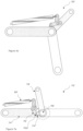
- part of an aircraft landing gear assembly is shown generally at 50.
- the landing gear assembly is similar to the landing gear assembly described with reference to Figures 2a to 2e and, for brevity, the following description will focus on the differences.
- a first structural member 52 which could for example be a lower stay arm, is provided with a protruding lug member 52a at the end carrying the apex pivot pin P1.
- the lug member 52a is pivotally coupled to a control link 56 via pivot pin P2.
- the lug member 52a is angularly offset with respect to an axis through the apex pivot pin P1 and distal mounting pivot pin P3 of the first structural member 52, such that the pivot pin P2 is offset, in this embodiment, by an angle of roughly 30 degrees.
- the whole linkage can be 'clocked round' for example, to bring the lug member onto the axis.
- a second structural member 54 which could for example be an upper stay arm, is pivotally coupled to the first structural member 52 via the apex pivot pin P1.
- a generally C-shaped arm member 58 is pivotally mounted to the second structural member 54 via pivot pin P4 at a location which is generally in line with the pivot pin P2 when the first and second structural members 52, 54 are axially aligned, as shown in Figure 3a .
- the C shaped member 58 is formed from four straight sections rigidly fixed to one another to define the C shape, but can take any suitable form, such as a T shape or bell crank.
- the distance between the axes of pivot pin P4 and pivot pin P2 can be roughly equal to the distance between the axes of pivot pin P2 and pivot pin P1.
- Figure 8 illustrates a first portion of movement with a maximum magnification factor of roughly 1.3 and for later movement, assuming that the lock link swings through 70 degrees, a second portion of movement with an extension reduction by a factor of 0.265 or roughly a reduction of 4.
- Components of the aircraft landing gear assembly according to embodiments of the invention can be implemented from conventional aerospace materials, such as titanium, aluminium and/or steel for structural members, polymer or metal bearings etc.
Landscapes
- Engineering & Computer Science (AREA)
- Mechanical Engineering (AREA)
- Aviation & Aerospace Engineering (AREA)
- Transmission Devices (AREA)
Claims (13)
- Ensemble train d'atterrissage d'aéronef comprenant :un premier élément structural (52') ;un second élément structural (54') accouplé de manière pivotante au premier élément structural au niveau d'un point de pivotement de sommet (P1') de manière à être mobile entre un premier état angulaire et un second état angulaire distinct du premier état angulaire ;dans lequel le premier élément structural (52') est un premier bras de l'une d'une contrefiche ou d'une contrefiche secondaire et le second élément structural (54') est un second bras d'une seconde de la contrefiche ou de la contrefiche secondaire ;un ressort de verrouillage vers le bas (60') ayant une première région d'extrémité accouplée de manière pivotante à une structure de montage et étant agencé sous tension pour solliciter les premier et second éléments structuraux pour adopter le premier état angulaire ; etun ensemble de liaison, l'ensemble de liaison comprenant :un élément de bras (58') accouplé de manière pivotante à l'un des premier et second éléments structuraux au niveau d'un point de pivotement de bras (P2'), le bras ayant une première région d'extrémité accouplée de manière pivotante à une seconde région d'extrémité du ressort de verrouillage vers le bas ; et caractérisé en ce qu'il comprend en outreune biellette de commande (56') accouplée de manière pivotante à l'un des premier et second éléments structuraux au niveau d'un premier point de pivotement de biellette de commande (P4') et accouplée de manière pivotante à l'élément de bras au niveau d'un deuxième point de pivotement de biellette de commande (P5') de sorte que, lorsque les premier et second éléments structuraux se déplacent l'un par rapport à l'autre à partir du premier état angulaire en direction du second état angulaire, le premier point de pivotement de biellette de commande se déplace sur le centre, à travers un axe ou un plan coupant en deux parties égales le point de pivotement de sommet et le deuxième point de pivotement de biellette de commande.
- Ensemble train d'atterrissage d'aéronef selon la revendication 1, dans lequel l'ensemble de liaison est agencé de sorte que, lorsque les éléments structuraux se déplacent du premier état angulaire au second état angulaire, l'extension de ressort est agrandie par rapport à un arrangement équivalent ayant une connexion directe entre la seconde région d'extrémité du ressort de verrouillage vers le bas (60') et l'élément structural (52', 54')
pour une première partie du mouvement et/ou est réduite par rapport à l'agencement de connexion directe pour une seconde partie du mouvement. - Ensemble train d'atterrissage d'aéronef selon la revendication 2, dans lequel l'agrandissement est d'au moins un facteur de 1,2 et/ou la réduction est d'au moins un facteur de 2 et de préférence le facteur de réduction a pour résultat que le ressort de verrouillage vers le bas (60') soit plus court dans l'état arrimé que dans l'état déployé.
- Ensemble train d'atterrissage d'aéronef selon la revendication 2 ou la revendication 3, dans lequel la seconde partie du mouvement commence à l'intérieur d'une première moitié du mouvement total du train d'atterrissage de l'état entièrement déployé à l'état entièrement arrimé.
- Ensemble train d'atterrissage d'aéronef selon une quelconque revendication précédente, dans lequel l'élément de bras (58') est longitudinalement non linéaire.
- Ensemble train d'atterrissage d'aéronef selon la revendication 5, dans lequel l'élément de bras (58') est longitudinalement en forme de C.
- Ensemble train d'atterrissage d'aéronef selon une quelconque revendication précédente, dans lequel l'élément de bras (58') est accouplé de manière pivotante au second élément structural (54'), le point de pivotement de bras (P2') est au niveau d'une première région d'extrémité du bras et la biellette de commande (56') est accouplée de manière pivotante au premier élément structural (52').
- Ensemble train d'atterrissage d'aéronef selon la revendication 7, dans lequel le deuxième point de pivotement de biellette de commande (P5') est situé sur l'élément de bras (58') au niveau d'un emplacement qui est plus proche du point de pivotement de bras (P2') que le point par le biais duquel le bras est accouplé de manière pivotante au ressort de verrouillage vers le bas (60').
- Ensemble train d'atterrissage d'aéronef selon l'une quelconque des revendications 1 à 6, dans lequel le point de pivotement de bras (P2') est au niveau d'une région centrale de l'élément de bras (58').
- Ensemble train d'atterrissage d'aéronef selon la revendication 9, dans lequel l'élément de bras (58') est accouplé de manière pivotante au premier élément structural (52'), la biellette de commande (56') est accouplée de manière pivotante au second élément structural (54') et le deuxième point de pivotement de biellette de commande est situé au niveau d'une seconde région d'extrémité de l'élément de bras (58') opposée à la première région d'extrémité qui est accouplée de manière pivotante au ressort de verrouillage vers le bas (60').
- Ensemble train d'atterrissage d'aéronef selon la revendication 9, dans lequel l'élément de bras (58') est accouplé de manière pivotante au premier élément structural (52'), la biellette de commande (56') est accouplée de manière pivotante au second élément structural (54') et l'ensemble de liaison comprend en outre un second bras en forme de C (102) accouplé de manière pivotante au second élément structural au niveau d'un point de pivotement de second bras situé au niveau d'une région centrale du second bras, le deuxième point de pivotement de biellette de commande étant situé au niveau d'une première région d'extrémité du second bras, l'ensemble de liaison comprenant en outre une seconde biellette de commande (100) accouplée de manière pivotante à l'un des premier et second éléments structuraux au niveau d'un premier point de pivotement de biellette de commande et accouplée de manière pivotante à une seconde extrémité du second bras au niveau d'un troisième point de pivotement de biellette de commande et accouplée de manière pivotante à une seconde extrémité du bras en forme de C au niveau d'un quatrième point de pivotement de biellette de commande de sorte que, lorsque les premier et second éléments structuraux se déplacent l'un par rapport à l'autre à partir de l'état aligné en direction de l'état non aligné, le premier point de pivotement de biellette de commande se déplace sur le centre, à travers un axe ou un plan coupant en deux parties égales le point de pivotement de sommet et le deuxième point de pivotement de biellette de commande et le troisième point de pivotement de biellette de commande se déplace sur le centre, à travers un axe ou un plan coupant en deux parties égales le point de pivotement de bras et le quatrième point de pivotement de biellette de commande.
- Ensemble train d'atterrissage d'aéronef selon une quelconque revendication précédente, comprenant en outre :une jambe d'amortisseur (24) agencée pour être déplacée entre un état déployé pour le décollage et l'atterrissage et un état arrimé pour le vol ; etune roue (30) ou un autre ensemble en contact avec le sol accouplé(e) à la jambe d'amortisseur, dans lequel l'ensemble train d'atterrissage est agencé de sorte que la jambe d'amortisseur soit maintenue dans l'état déployé lorsque les premier et second éléments structuraux sont dans le premier état angulaire.
- Aéronef comportant un ou plusieurs ensembles train d'atterrissage d'aéronef selon une quelconque revendication précédente.
Priority Applications (5)
| Application Number | Priority Date | Filing Date | Title |
|---|---|---|---|
| EP21194061.4A EP4140880B1 (fr) | 2021-08-31 | 2021-08-31 | Ensemble train d'atterrissage d'aéronef |
| US18/684,605 US12377966B2 (en) | 2021-08-31 | 2022-08-26 | Aircraft landing gear assembly |
| PCT/EP2022/073770 WO2023031035A1 (fr) | 2021-08-31 | 2022-08-26 | Ensemble train d'atterrissage d'aéronef |
| CA3228754A CA3228754A1 (fr) | 2021-08-31 | 2022-08-26 | Ensemble train d'atterrissage d'aeronef |
| CN202280058270.0A CN117897335A (zh) | 2021-08-31 | 2022-08-26 | 飞行器起落架组件 |
Applications Claiming Priority (1)
| Application Number | Priority Date | Filing Date | Title |
|---|---|---|---|
| EP21194061.4A EP4140880B1 (fr) | 2021-08-31 | 2021-08-31 | Ensemble train d'atterrissage d'aéronef |
Publications (2)
| Publication Number | Publication Date |
|---|---|
| EP4140880A1 EP4140880A1 (fr) | 2023-03-01 |
| EP4140880B1 true EP4140880B1 (fr) | 2025-03-12 |
Family
ID=77564021
Family Applications (1)
| Application Number | Title | Priority Date | Filing Date |
|---|---|---|---|
| EP21194061.4A Active EP4140880B1 (fr) | 2021-08-31 | 2021-08-31 | Ensemble train d'atterrissage d'aéronef |
Country Status (5)
| Country | Link |
|---|---|
| US (1) | US12377966B2 (fr) |
| EP (1) | EP4140880B1 (fr) |
| CN (1) | CN117897335A (fr) |
| CA (1) | CA3228754A1 (fr) |
| WO (1) | WO2023031035A1 (fr) |
Family Cites Families (5)
| Publication number | Priority date | Publication date | Assignee | Title |
|---|---|---|---|---|
| FR2503086A1 (fr) * | 1981-04-02 | 1982-10-08 | Messier Hispano Sa | Contrefiche, notamment pour application de la technique aeronautique |
| FR2915731B1 (fr) * | 2007-05-03 | 2009-07-03 | Messier Dowty Sa Sa | Dispositif de verrouillage de contreventement pour atterrisseur d'aeronef |
| US8590835B2 (en) * | 2010-05-11 | 2013-11-26 | Goodrich Corporation | Electrically powered downlock actuation system |
| US10293920B2 (en) * | 2016-09-02 | 2019-05-21 | The Boeing Company | Landing gear toggle lock mechanism |
| EP4122821A1 (fr) * | 2021-07-21 | 2023-01-25 | Safran Landing Systems UK Limited | Jambe d'amortisseur de train d'atterrissage d'avion |
-
2021
- 2021-08-31 EP EP21194061.4A patent/EP4140880B1/fr active Active
-
2022
- 2022-08-26 WO PCT/EP2022/073770 patent/WO2023031035A1/fr not_active Ceased
- 2022-08-26 CA CA3228754A patent/CA3228754A1/fr active Pending
- 2022-08-26 CN CN202280058270.0A patent/CN117897335A/zh active Pending
- 2022-08-26 US US18/684,605 patent/US12377966B2/en active Active
Also Published As
| Publication number | Publication date |
|---|---|
| CN117897335A (zh) | 2024-04-16 |
| US20250121932A1 (en) | 2025-04-17 |
| US12377966B2 (en) | 2025-08-05 |
| CA3228754A1 (fr) | 2023-03-09 |
| EP4140880A1 (fr) | 2023-03-01 |
| WO2023031035A1 (fr) | 2023-03-09 |
Similar Documents
| Publication | Publication Date | Title |
|---|---|---|
| US9764826B2 (en) | Landing gear assembly and methods | |
| EP3069993B1 (fr) | Ensemble de train d'atterrissage d'avion | |
| EP3069991B1 (fr) | Ensemble de train d'atterrissage d'avion | |
| US12097950B2 (en) | Retractable aircraft landing gear | |
| US12397904B2 (en) | Aircraft landing gear assembly comprising a cam surface and a leaf spring, wherein the second end region of the leaf spring comprises a cam follower | |
| EP2937281B1 (fr) | Mécanisme d'articulation de poutre de bogie | |
| EP4140880B1 (fr) | Ensemble train d'atterrissage d'aéronef | |
| US11059572B2 (en) | Landing gear | |
| US11383826B2 (en) | Aircraft landing gear component | |
| GB2586824A (en) | Landing gear assembly |
Legal Events
| Date | Code | Title | Description |
|---|---|---|---|
| PUAI | Public reference made under article 153(3) epc to a published international application that has entered the european phase |
Free format text: ORIGINAL CODE: 0009012 |
|
| STAA | Information on the status of an ep patent application or granted ep patent |
Free format text: STATUS: THE APPLICATION HAS BEEN PUBLISHED |
|
| AK | Designated contracting states |
Kind code of ref document: A1 Designated state(s): AL AT BE BG CH CY CZ DE DK EE ES FI FR GB GR HR HU IE IS IT LI LT LU LV MC MK MT NL NO PL PT RO RS SE SI SK SM TR |
|
| STAA | Information on the status of an ep patent application or granted ep patent |
Free format text: STATUS: REQUEST FOR EXAMINATION WAS MADE |
|
| 17P | Request for examination filed |
Effective date: 20230321 |
|
| RBV | Designated contracting states (corrected) |
Designated state(s): AL AT BE BG CH CY CZ DE DK EE ES FI FR GB GR HR HU IE IS IT LI LT LU LV MC MK MT NL NO PL PT RO RS SE SI SK SM TR |
|
| STAA | Information on the status of an ep patent application or granted ep patent |
Free format text: STATUS: EXAMINATION IS IN PROGRESS |
|
| 17Q | First examination report despatched |
Effective date: 20240117 |
|
| GRAP | Despatch of communication of intention to grant a patent |
Free format text: ORIGINAL CODE: EPIDOSNIGR1 |
|
| STAA | Information on the status of an ep patent application or granted ep patent |
Free format text: STATUS: GRANT OF PATENT IS INTENDED |
|
| INTG | Intention to grant announced |
Effective date: 20241022 |
|
| GRAS | Grant fee paid |
Free format text: ORIGINAL CODE: EPIDOSNIGR3 |
|
| GRAA | (expected) grant |
Free format text: ORIGINAL CODE: 0009210 |
|
| STAA | Information on the status of an ep patent application or granted ep patent |
Free format text: STATUS: THE PATENT HAS BEEN GRANTED |
|
| AK | Designated contracting states |
Kind code of ref document: B1 Designated state(s): AL AT BE BG CH CY CZ DE DK EE ES FI FR GB GR HR HU IE IS IT LI LT LU LV MC MK MT NL NO PL PT RO RS SE SI SK SM TR |
|
| REG | Reference to a national code |
Ref country code: GB Ref legal event code: FG4D |
|
| REG | Reference to a national code |
Ref country code: CH Ref legal event code: EP |
|
| REG | Reference to a national code |
Ref country code: DE Ref legal event code: R096 Ref document number: 602021027420 Country of ref document: DE |
|
| REG | Reference to a national code |
Ref country code: IE Ref legal event code: FG4D |
|
| PG25 | Lapsed in a contracting state [announced via postgrant information from national office to epo] |
Ref country code: RS Free format text: LAPSE BECAUSE OF FAILURE TO SUBMIT A TRANSLATION OF THE DESCRIPTION OR TO PAY THE FEE WITHIN THE PRESCRIBED TIME-LIMIT Effective date: 20250612 |
|
| PG25 | Lapsed in a contracting state [announced via postgrant information from national office to epo] |
Ref country code: FI Free format text: LAPSE BECAUSE OF FAILURE TO SUBMIT A TRANSLATION OF THE DESCRIPTION OR TO PAY THE FEE WITHIN THE PRESCRIBED TIME-LIMIT Effective date: 20250312 |
|
| PG25 | Lapsed in a contracting state [announced via postgrant information from national office to epo] |
Ref country code: ES Free format text: LAPSE BECAUSE OF FAILURE TO SUBMIT A TRANSLATION OF THE DESCRIPTION OR TO PAY THE FEE WITHIN THE PRESCRIBED TIME-LIMIT Effective date: 20250312 |
|
| REG | Reference to a national code |
Ref country code: LT Ref legal event code: MG9D |
|
| PG25 | Lapsed in a contracting state [announced via postgrant information from national office to epo] |
Ref country code: NO Free format text: LAPSE BECAUSE OF FAILURE TO SUBMIT A TRANSLATION OF THE DESCRIPTION OR TO PAY THE FEE WITHIN THE PRESCRIBED TIME-LIMIT Effective date: 20250612 |
|
| PG25 | Lapsed in a contracting state [announced via postgrant information from national office to epo] |
Ref country code: HR Free format text: LAPSE BECAUSE OF FAILURE TO SUBMIT A TRANSLATION OF THE DESCRIPTION OR TO PAY THE FEE WITHIN THE PRESCRIBED TIME-LIMIT Effective date: 20250312 |
|
| REG | Reference to a national code |
Ref country code: NL Ref legal event code: MP Effective date: 20250312 |
|
| PG25 | Lapsed in a contracting state [announced via postgrant information from national office to epo] |
Ref country code: LV Free format text: LAPSE BECAUSE OF FAILURE TO SUBMIT A TRANSLATION OF THE DESCRIPTION OR TO PAY THE FEE WITHIN THE PRESCRIBED TIME-LIMIT Effective date: 20250312 |
|
| PG25 | Lapsed in a contracting state [announced via postgrant information from national office to epo] |
Ref country code: GR Free format text: LAPSE BECAUSE OF FAILURE TO SUBMIT A TRANSLATION OF THE DESCRIPTION OR TO PAY THE FEE WITHIN THE PRESCRIBED TIME-LIMIT Effective date: 20250613 Ref country code: BG Free format text: LAPSE BECAUSE OF FAILURE TO SUBMIT A TRANSLATION OF THE DESCRIPTION OR TO PAY THE FEE WITHIN THE PRESCRIBED TIME-LIMIT Effective date: 20250312 |
|
| REG | Reference to a national code |
Ref country code: AT Ref legal event code: MK05 Ref document number: 1774843 Country of ref document: AT Kind code of ref document: T Effective date: 20250312 |
|
| PG25 | Lapsed in a contracting state [announced via postgrant information from national office to epo] |
Ref country code: NL Free format text: LAPSE BECAUSE OF FAILURE TO SUBMIT A TRANSLATION OF THE DESCRIPTION OR TO PAY THE FEE WITHIN THE PRESCRIBED TIME-LIMIT Effective date: 20250312 |
|
| PG25 | Lapsed in a contracting state [announced via postgrant information from national office to epo] |
Ref country code: SE Free format text: LAPSE BECAUSE OF FAILURE TO SUBMIT A TRANSLATION OF THE DESCRIPTION OR TO PAY THE FEE WITHIN THE PRESCRIBED TIME-LIMIT Effective date: 20250312 |
|
| PG25 | Lapsed in a contracting state [announced via postgrant information from national office to epo] |
Ref country code: SM Free format text: LAPSE BECAUSE OF FAILURE TO SUBMIT A TRANSLATION OF THE DESCRIPTION OR TO PAY THE FEE WITHIN THE PRESCRIBED TIME-LIMIT Effective date: 20250312 |
|
| PG25 | Lapsed in a contracting state [announced via postgrant information from national office to epo] |
Ref country code: PT Free format text: LAPSE BECAUSE OF FAILURE TO SUBMIT A TRANSLATION OF THE DESCRIPTION OR TO PAY THE FEE WITHIN THE PRESCRIBED TIME-LIMIT Effective date: 20250714 |
|
| PGFP | Annual fee paid to national office [announced via postgrant information from national office to epo] |
Ref country code: DE Payment date: 20250819 Year of fee payment: 5 |
|
| PG25 | Lapsed in a contracting state [announced via postgrant information from national office to epo] |
Ref country code: PL Free format text: LAPSE BECAUSE OF FAILURE TO SUBMIT A TRANSLATION OF THE DESCRIPTION OR TO PAY THE FEE WITHIN THE PRESCRIBED TIME-LIMIT Effective date: 20250312 Ref country code: IT Free format text: LAPSE BECAUSE OF FAILURE TO SUBMIT A TRANSLATION OF THE DESCRIPTION OR TO PAY THE FEE WITHIN THE PRESCRIBED TIME-LIMIT Effective date: 20250312 |
|
| PGFP | Annual fee paid to national office [announced via postgrant information from national office to epo] |
Ref country code: GB Payment date: 20250825 Year of fee payment: 5 |
|
| PG25 | Lapsed in a contracting state [announced via postgrant information from national office to epo] |
Ref country code: AT Free format text: LAPSE BECAUSE OF FAILURE TO SUBMIT A TRANSLATION OF THE DESCRIPTION OR TO PAY THE FEE WITHIN THE PRESCRIBED TIME-LIMIT Effective date: 20250312 |
|
| PGFP | Annual fee paid to national office [announced via postgrant information from national office to epo] |
Ref country code: FR Payment date: 20250827 Year of fee payment: 5 |
|
| PG25 | Lapsed in a contracting state [announced via postgrant information from national office to epo] |
Ref country code: CZ Free format text: LAPSE BECAUSE OF FAILURE TO SUBMIT A TRANSLATION OF THE DESCRIPTION OR TO PAY THE FEE WITHIN THE PRESCRIBED TIME-LIMIT Effective date: 20250312 Ref country code: EE Free format text: LAPSE BECAUSE OF FAILURE TO SUBMIT A TRANSLATION OF THE DESCRIPTION OR TO PAY THE FEE WITHIN THE PRESCRIBED TIME-LIMIT Effective date: 20250312 |
|
| PG25 | Lapsed in a contracting state [announced via postgrant information from national office to epo] |
Ref country code: RO Free format text: LAPSE BECAUSE OF FAILURE TO SUBMIT A TRANSLATION OF THE DESCRIPTION OR TO PAY THE FEE WITHIN THE PRESCRIBED TIME-LIMIT Effective date: 20250312 |
|
| PG25 | Lapsed in a contracting state [announced via postgrant information from national office to epo] |
Ref country code: SK Free format text: LAPSE BECAUSE OF FAILURE TO SUBMIT A TRANSLATION OF THE DESCRIPTION OR TO PAY THE FEE WITHIN THE PRESCRIBED TIME-LIMIT Effective date: 20250312 |
|
| PG25 | Lapsed in a contracting state [announced via postgrant information from national office to epo] |
Ref country code: IS Free format text: LAPSE BECAUSE OF FAILURE TO SUBMIT A TRANSLATION OF THE DESCRIPTION OR TO PAY THE FEE WITHIN THE PRESCRIBED TIME-LIMIT Effective date: 20250712 |
|
| REG | Reference to a national code |
Ref country code: DE Ref legal event code: R097 Ref document number: 602021027420 Country of ref document: DE |
|
| PG25 | Lapsed in a contracting state [announced via postgrant information from national office to epo] |
Ref country code: DK Free format text: LAPSE BECAUSE OF FAILURE TO SUBMIT A TRANSLATION OF THE DESCRIPTION OR TO PAY THE FEE WITHIN THE PRESCRIBED TIME-LIMIT Effective date: 20250312 |
|
| PLBE | No opposition filed within time limit |
Free format text: ORIGINAL CODE: 0009261 |
|
| STAA | Information on the status of an ep patent application or granted ep patent |
Free format text: STATUS: NO OPPOSITION FILED WITHIN TIME LIMIT |
|
| REG | Reference to a national code |
Ref country code: CH Ref legal event code: L10 Free format text: ST27 STATUS EVENT CODE: U-0-0-L10-L00 (AS PROVIDED BY THE NATIONAL OFFICE) Effective date: 20260121 |
|
| 26N | No opposition filed |
Effective date: 20251215 |
|
| REG | Reference to a national code |
Ref country code: CH Ref legal event code: H13 Free format text: ST27 STATUS EVENT CODE: U-0-0-H10-H13 (AS PROVIDED BY THE NATIONAL OFFICE) Effective date: 20260324 |
|
| PG25 | Lapsed in a contracting state [announced via postgrant information from national office to epo] |
Ref country code: MC Free format text: LAPSE BECAUSE OF FAILURE TO SUBMIT A TRANSLATION OF THE DESCRIPTION OR TO PAY THE FEE WITHIN THE PRESCRIBED TIME-LIMIT Effective date: 20250312 |
|
| PG25 | Lapsed in a contracting state [announced via postgrant information from national office to epo] |
Ref country code: LU Free format text: LAPSE BECAUSE OF NON-PAYMENT OF DUE FEES Effective date: 20250831 |
|
| PG25 | Lapsed in a contracting state [announced via postgrant information from national office to epo] |
Ref country code: CH Free format text: LAPSE BECAUSE OF NON-PAYMENT OF DUE FEES Effective date: 20250831 |