EP4140928A1 - Dispositif pour l'enroulement continu de matériaux filiformes dans le même sens dans des enrouleurs doubles - Google Patents
Dispositif pour l'enroulement continu de matériaux filiformes dans le même sens dans des enrouleurs doubles Download PDFInfo
- Publication number
- EP4140928A1 EP4140928A1 EP21193477.3A EP21193477A EP4140928A1 EP 4140928 A1 EP4140928 A1 EP 4140928A1 EP 21193477 A EP21193477 A EP 21193477A EP 4140928 A1 EP4140928 A1 EP 4140928A1
- Authority
- EP
- European Patent Office
- Prior art keywords
- winding
- spool
- coils
- winding material
- catch
- Prior art date
- Legal status (The legal status is an assumption and is not a legal conclusion. Google has not performed a legal analysis and makes no representation as to the accuracy of the status listed.)
- Withdrawn
Links
- 238000004804 winding Methods 0.000 title claims abstract description 138
- 239000000463 material Substances 0.000 title claims abstract description 50
- 238000000034 method Methods 0.000 claims abstract description 24
- 238000012546 transfer Methods 0.000 description 10
- 238000013461 design Methods 0.000 description 8
- 238000004519 manufacturing process Methods 0.000 description 4
- 239000004753 textile Substances 0.000 description 3
- 238000011161 development Methods 0.000 description 2
- 230000018109 developmental process Effects 0.000 description 2
- 230000006870 function Effects 0.000 description 2
- 238000007373 indentation Methods 0.000 description 2
- 238000003780 insertion Methods 0.000 description 2
- 230000037431 insertion Effects 0.000 description 2
- 238000011144 upstream manufacturing Methods 0.000 description 2
- RYGMFSIKBFXOCR-UHFFFAOYSA-N Copper Chemical compound [Cu] RYGMFSIKBFXOCR-UHFFFAOYSA-N 0.000 description 1
- 230000005540 biological transmission Effects 0.000 description 1
- 239000011248 coating agent Substances 0.000 description 1
- 238000000576 coating method Methods 0.000 description 1
- 238000010924 continuous production Methods 0.000 description 1
- 229910052802 copper Inorganic materials 0.000 description 1
- 239000010949 copper Substances 0.000 description 1
- 238000002788 crimping Methods 0.000 description 1
- 230000001419 dependent effect Effects 0.000 description 1
- 230000000881 depressing effect Effects 0.000 description 1
- 238000001125 extrusion Methods 0.000 description 1
- 239000000835 fiber Substances 0.000 description 1
- 239000011521 glass Substances 0.000 description 1
- 238000009434 installation Methods 0.000 description 1
- 238000003825 pressing Methods 0.000 description 1
- 238000012545 processing Methods 0.000 description 1
- 238000004904 shortening Methods 0.000 description 1
- 238000003860 storage Methods 0.000 description 1
Images


Classifications
-
- B—PERFORMING OPERATIONS; TRANSPORTING
- B65—CONVEYING; PACKING; STORING; HANDLING THIN OR FILAMENTARY MATERIAL
- B65H—HANDLING THIN OR FILAMENTARY MATERIAL, e.g. SHEETS, WEBS, CABLES
- B65H67/00—Replacing or removing cores, receptacles, or completed packages at paying-out, winding, or depositing stations
- B65H67/04—Arrangements for removing completed take-up packages and or replacing by cores, formers, or empty receptacles at winding or depositing stations; Transferring material between adjacent full and empty take-up elements
- B65H67/044—Continuous winding apparatus for winding on two or more winding heads in succession
- B65H67/052—Continuous winding apparatus for winding on two or more winding heads in succession having two or more winding heads arranged in parallel to each other
-
- B—PERFORMING OPERATIONS; TRANSPORTING
- B65—CONVEYING; PACKING; STORING; HANDLING THIN OR FILAMENTARY MATERIAL
- B65H—HANDLING THIN OR FILAMENTARY MATERIAL, e.g. SHEETS, WEBS, CABLES
- B65H65/00—Securing material to cores or formers
-
- B—PERFORMING OPERATIONS; TRANSPORTING
- B65—CONVEYING; PACKING; STORING; HANDLING THIN OR FILAMENTARY MATERIAL
- B65H—HANDLING THIN OR FILAMENTARY MATERIAL, e.g. SHEETS, WEBS, CABLES
- B65H2701/00—Handled material; Storage means
- B65H2701/30—Handled filamentary material
- B65H2701/31—Textiles threads or artificial strands of filaments
Definitions
- the present invention relates to a method and a device for the continuous winding of strand-like material on double spools according to the preamble of patent claim 1.
- strand-like material means in particular wires, strands, wires, textile threads, etc. on spools, which have the orthogonal to their winding axis are designed asymmetrically, e.g. with a monoconical winding core and/or have to be wound in the same direction for functional reasons.
- Such windings of strand-shaped goods are produced, for example, in a continuous process in highly productive extrusion systems for coating copper wires and strands, glass and textile fibers into so-called cores for the automotive, data and energy transmission sector.
- continuously winding double spools are state of the art in the cable, wire, hose and textile industries.
- the specific implementation is different in each case. This applies, for example, to the arrangement and movement of the winding points in space and the functional design of the device elements for transferring the winding material from the fully wound spool to the empty spool without reducing the production speed of the upstream system parts. What they all have in common, whether with a horizontal or vertical winding axis, is the axis-parallel arrangement of the winding positions.
- the winding basket which can be rotated around the vertical, pivots by 180° into one to transfer the winding material from the full spool to the empty spool and then each other direction.
- no slip ring contacts are required to supply the winding drives and no pressure medium supply via rotary feedthroughs is required for the advantageous clamping of the coils "axleless" between quills.
- Another advantage of this design is the good connection to automated package handling.
- the present invention is based on the object of creating a method that allows the elongated product resulting from the previous production process to be wound onto spools on automatic double spoolers in such a way that, with regard to the spool geometry, a winding direction is in the same direction, regardless of the winding point the same start and end of winding can be produced and thus all coils wound on the double spooler can be used for the further technological work step.
- the method according to the invention is accordingly characterized in that the coils are used opposite to one another in their alignment towards the drive side and the coils are wound onto the coils at the opposite ends of the winding material on the coils due to the alignment.
- a device for carrying out the method of the type mentioned is preferably characterized in that it comprises at least one device for turning over the winding material from the winding material beginning of a full spool to the winding material beginning of an empty spool.
- such a device is preferably designed so that it allows automatic double spoolers to be equipped in such a way that, while maintaining the conventional axis-parallel arrangement of the winding points with spools that are driven and held axislessly between sleeves, a winding of all spools directed in the same direction can be produced.
- Automatic means that the process of inserting the empty bobbins into the machine from storage on an infeed idler conveyor or ramp to the winding point of the bobbin and removing the fully wound bobbin from the winding point to the outfeed idler roller conveyor or ramp is full program-controlled.
- the advantage here is the possibility of arranging the feed and unloading units together on one side of the machine and thus shortening package handling.
- each spool In the case of semi-automatic double spoolers, each spool must be fed individually for loading to one or the other winding position.
- the disadvantage here is the inevitably higher bobbin handling effort by the operator.
- the respective winding point is alternately loaded with the empty spool in such a way that this is always successively wound in the same winding direction after the turning process of the winding material.
- the winding material is transferred from the full spool to the empty spool and caught, contrary to the previously known designs, not only on the driven spool flange side but also on the opposite flange side.
- a transfer device which is arranged on the spool drive side and whose functional elements enable the running winding material to be drawn in for catching in the catching plane on the drive-side flange and the opposite flange of the empty spool.
- two catching planes are preferably arranged, which allow the running winding material to be drawn in for catching in the catching plane on the drive-side flange and the opposite flange of the empty spool.
- the device according to the invention for the continuous winding of strand-like material on double spoolers comprises spools 1, 2, which are mounted on both sides and are to be inserted parallel to the axis, which can be successively wound with a strand-like material 44 in the same direction and which are used alternately automatically or semi-automatically after they have been wound.
- FIG. 5 shows the device according to the invention in an advantageous embodiment
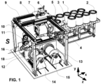
- the implementation of a winding of the bobbins in the same direction with regard to the winding direction 43, the beginning of the winding 42 and the end of the winding is exemplified below on an automatic double spooler as in FIG Fig.1 shown with traversing winding units and monoconical coils.
- a further embodiment of the device according to the invention e.g 8 .
- the winding material 16 arriving from the left is wound onto the right-hand spool 13 which is just being completed.
- the dancer unit 11 with the transfer roller 18 is already positioned on the left over the empty spool 1 for the transfer process.
- the inlet idler roller conveyor 3 for the empty bobbins 1 and the outlet idler roller conveyor 4 for the full bobbins 2 are arranged.
- the coils are arranged vertically in a special way and are conveyed intermittently in the loading cycle.
- the next pending empty bobbin 1 for installation in the double spooler is pushed outside the machine housing from the infeed idler roller conveyor 3 onto the pivoting device 5 aligned with the exit idler roller conveyor 4 .
- the empty bobbin 1 With its pivoting in the xy plane, the empty bobbin 1 moves from the vertical position to the horizontal and is thus ready to be taken over by the bobbin parallel gripper 8, which is mounted at the lower end of a lifting-pivoting column 6 and through this in direction can be raised or lowered along the y-axis and swiveled around the z-axis +/- 180°.
- This lifting and pivoting column 6 is in turn attached to a transport carriage 7 which can be moved along the paired linear guide units 9 in the direction of the x-axis and these in turn can be moved via a pair of linear guide units 10 in the direction of the z-axis. In this way, the already filled coil can be changed at your winding point 14 or 15 without interrupting the winding process at the other winding point.
- the bobbins can ultimately be installed and removed in the winding devices by means of a 180° rotary movement of the lifting and swiveling column in one direction or the other parallel to the z-axis and, on the other hand, also oriented to the swiveling device 5 for winding -Out or -Entry to be passed.
- the device according to the invention relates to the special design and arrangement of the functional parts catching hoods 19 and 29, the catching hook rollers 21 and the catcher discs 25 and 27 arranged on both sides of the bobbin for transferring and catching the winding material 16 from the completing bobbin 13 to the empty bobbin 1 at the same winding speed.
- the geometric initial conditions are shown as an example for the winding material transfer from the right to the left coil.
- Both figures represent a plan view of the in 2 shown arrangement.
- the winding positions guided on the carriages 33, 34, 35, 36 traverse for laying the winding material on the spools.
- the spools are always used in opposition to one another.
- In 3 shows the smallest diameter of the winding cone of the empty spool 1 on the left towards the drive side (winding drive 30) and the smallest diameter of the winding cone of the completing spool 13 in the opposite direction.
- the empty bobbin 1 is positioned with the inside of the driven flange in the catching plane or in alignment with the winding material run over the traversing rollers 18 .
- the catching process begins with the pressing down of the winding material 16 until it touches the spool core of the empty spool 1 .
- the catch hook vertical drive 23 moves the catch hook rollers 21 from position "y1z2" down to position "y2z2" (see also figure 5 ).
- the catch hook rollers 21 are pulled back in the z-direction to Pos. during which it is prevented from being caught by the catcher disk 25 at the right catcher hood 29 .
- the loose end of the decelerating full bobbin is now left in the rear infeed 37 of the catching hood 19 (see also Fig.5 ) and guided until the coil comes to a standstill.
- the catch hook rollers 21 are moved vertically upwards to their starting position "y1z1".
- In 4 shows the smallest diameter of the winding cone of the empty spool 1 on the right side opposite to the drive side (drives 30) and the smallest diameter of the winding cone of the completing spool 13 to the drive side.
- the empty spool 1 is positioned with the inside of the non-driven flange in the catching plane or in alignment with the winding material run over the traversing rollers 18 .
- the catching process begins with the catch hook rollers 21 moving forward from the starting position “y1z1" to position “y3z3” and then lowering to position “y2z3” and thus depressing the Winding material 16 until it touches the coil core of the empty coil 1. Then, via the horizontal drive 24 of the catch hook, the catch hook rollers move forward in the z-direction to position "y2z3", away from the winding drives 30.
- the right-hand catch disc 26 inevitably catches the winding material and shortly thereafter cuts it on the blade 41 of the right-hand catch hood 29, during which it is prevented from being caught by the catcher disc 27 at the left catcher hood 19.
- FIG. 8 shows a perspective view of a design of the device according to the invention for double spoolers with traversing laying rollers (not shown).
- a catch disk 26, 28 with a catch hood is assigned to each coil both on the drive side and on the opposite side, as well as 1 central catch hook-roller unit per side.
- each collecting hood requires only one feeder for the end of the winding material.
- Figures 9 and 10 schematically represent the same direction winding with contrary to built-in monoconical coils. If in 9 the same direction winding of both coils is shown wound clockwise seen on the flange with the larger core diameter, for example, the winding takes place in 10 counterclockwise. Orientation should be given by the respective inner beginning 42 of the winding material and the direction of the winding material 43 accumulating.
Landscapes
- Replacing, Conveying, And Pick-Finding For Filamentary Materials (AREA)
Priority Applications (1)
| Application Number | Priority Date | Filing Date | Title |
|---|---|---|---|
| EP21193477.3A EP4140928A1 (fr) | 2021-08-27 | 2021-08-27 | Dispositif pour l'enroulement continu de matériaux filiformes dans le même sens dans des enrouleurs doubles |
Applications Claiming Priority (1)
| Application Number | Priority Date | Filing Date | Title |
|---|---|---|---|
| EP21193477.3A EP4140928A1 (fr) | 2021-08-27 | 2021-08-27 | Dispositif pour l'enroulement continu de matériaux filiformes dans le même sens dans des enrouleurs doubles |
Publications (1)
| Publication Number | Publication Date |
|---|---|
| EP4140928A1 true EP4140928A1 (fr) | 2023-03-01 |
Family
ID=77520564
Family Applications (1)
| Application Number | Title | Priority Date | Filing Date |
|---|---|---|---|
| EP21193477.3A Withdrawn EP4140928A1 (fr) | 2021-08-27 | 2021-08-27 | Dispositif pour l'enroulement continu de matériaux filiformes dans le même sens dans des enrouleurs doubles |
Country Status (1)
| Country | Link |
|---|---|
| EP (1) | EP4140928A1 (fr) |
Cited By (1)
| Publication number | Priority date | Publication date | Assignee | Title |
|---|---|---|---|---|
| CN118405539A (zh) * | 2024-07-03 | 2024-07-30 | 山西同丰纤维机械有限公司 | 一种漆包线牵引卷绕装置 |
Citations (11)
| Publication number | Priority date | Publication date | Assignee | Title |
|---|---|---|---|---|
| DE1474231A1 (de) | 1964-01-16 | 1969-05-22 | Luetcke Werner Walter | Automatische Spulmaschine |
| CH537866A (de) | 1970-10-29 | 1973-06-15 | Thaelmann Schwermaschbau Veb | Verfahren und Vorrichtung zum längengerechten Aufwikkeln von drahtförmigem Gut mittels Doppelspuler |
| DE2403861A1 (de) * | 1973-03-26 | 1974-10-10 | Oberspree Kabelwerke Veb K | Wickelvorrichtung fuer automatische ringwickler |
| US3965528A (en) | 1974-10-01 | 1976-06-29 | Kissler & Co., Inc. | Universal elbow action lever handle |
| EP0003385B1 (fr) | 1978-01-30 | 1981-10-07 | Maillefer S.A. | Bobinoir double à fonctionnement continu |
| EP0056359B1 (fr) | 1981-01-12 | 1984-07-25 | Maillefer S.A. | Bobinoir double à fonctionnement continu |
| DE3534246A1 (de) | 1985-09-26 | 1987-03-26 | Akzo Gmbh | Verfahren zur herstellung von alkylen-bis-dithiocarbamaten oder deren ammoniak-addukten sowie danach herstellbare gemische |
| EP0504503B1 (fr) | 1991-03-22 | 1995-11-29 | KBE Elektrotechnik GmbH | Ensemble de conditionnement pour un rouleaux de câbles électriques en forme de cône tronqué |
| DE20205021U1 (de) | 2002-03-26 | 2002-09-26 | Schäfer Gehäusesysteme GmbH, 01277 Dresden | Computerfrontblende |
| DE202005021409U1 (de) | 2005-04-25 | 2008-02-21 | Maschinenfabrik Niehoff Gmbh & Co Kg | Vorrichtung zum Wickeln von langgestrecktem Wickelgut |
| DE102012024450A1 (de) | 2012-12-13 | 2014-06-18 | Maschinenfabrik Niehoff Gmbh & Co. Kg | Wickelspule für ein Gebinde, sowie Verfahren zu dessen Herstellung und Abwicklung |
-
2021
- 2021-08-27 EP EP21193477.3A patent/EP4140928A1/fr not_active Withdrawn
Patent Citations (11)
| Publication number | Priority date | Publication date | Assignee | Title |
|---|---|---|---|---|
| DE1474231A1 (de) | 1964-01-16 | 1969-05-22 | Luetcke Werner Walter | Automatische Spulmaschine |
| CH537866A (de) | 1970-10-29 | 1973-06-15 | Thaelmann Schwermaschbau Veb | Verfahren und Vorrichtung zum längengerechten Aufwikkeln von drahtförmigem Gut mittels Doppelspuler |
| DE2403861A1 (de) * | 1973-03-26 | 1974-10-10 | Oberspree Kabelwerke Veb K | Wickelvorrichtung fuer automatische ringwickler |
| US3965528A (en) | 1974-10-01 | 1976-06-29 | Kissler & Co., Inc. | Universal elbow action lever handle |
| EP0003385B1 (fr) | 1978-01-30 | 1981-10-07 | Maillefer S.A. | Bobinoir double à fonctionnement continu |
| EP0056359B1 (fr) | 1981-01-12 | 1984-07-25 | Maillefer S.A. | Bobinoir double à fonctionnement continu |
| DE3534246A1 (de) | 1985-09-26 | 1987-03-26 | Akzo Gmbh | Verfahren zur herstellung von alkylen-bis-dithiocarbamaten oder deren ammoniak-addukten sowie danach herstellbare gemische |
| EP0504503B1 (fr) | 1991-03-22 | 1995-11-29 | KBE Elektrotechnik GmbH | Ensemble de conditionnement pour un rouleaux de câbles électriques en forme de cône tronqué |
| DE20205021U1 (de) | 2002-03-26 | 2002-09-26 | Schäfer Gehäusesysteme GmbH, 01277 Dresden | Computerfrontblende |
| DE202005021409U1 (de) | 2005-04-25 | 2008-02-21 | Maschinenfabrik Niehoff Gmbh & Co Kg | Vorrichtung zum Wickeln von langgestrecktem Wickelgut |
| DE102012024450A1 (de) | 2012-12-13 | 2014-06-18 | Maschinenfabrik Niehoff Gmbh & Co. Kg | Wickelspule für ein Gebinde, sowie Verfahren zu dessen Herstellung und Abwicklung |
Cited By (1)
| Publication number | Priority date | Publication date | Assignee | Title |
|---|---|---|---|---|
| CN118405539A (zh) * | 2024-07-03 | 2024-07-30 | 山西同丰纤维机械有限公司 | 一种漆包线牵引卷绕装置 |
Similar Documents
| Publication | Publication Date | Title |
|---|---|---|
| DE2551290C2 (de) | Fadeneinziehvorrichtung für Doppelspulstellen auf Spulmaschinen | |
| DE69405957T2 (de) | Verfahren und Vorrichtung zum Aufspulen eines schmalen Bandes | |
| DE3809635C2 (fr) | ||
| DE2939675A1 (de) | Spulenwechseleinrichtung fuer textilmaschinen | |
| EP0921087A2 (fr) | Procédé et dispositif de bobinage pour bobiner un fil textile alimenté en continu | |
| EP1161397A1 (fr) | Procede et dispositif pour guider et couper un fil d'alimentation lors du changement de bobines | |
| DE102012016853A1 (de) | Verfahren zum Verbinden eines Ober- und Unterfadens an einer Arbeitsstelle einer Spulmaschine und Arbeitsstelle einer Spulmaschine | |
| EP0916612A2 (fr) | Dispositif et procédé pour guider et couper un fil textile alimenté en continu | |
| CH656865A5 (de) | Verfahren zum spulenwechsel beim aufspulen eines staendig anlaufenden fadens und aufspulvorrichtung. | |
| DE102012016854A1 (de) | Verfahren zum Verbinden eines Ober- und Unterfadens an einer Arbeitsstelle einer Spulmaschine und Arbeitsstelle einer Spulmaschine | |
| CH618943A5 (fr) | ||
| EP1452474B1 (fr) | Procédé et dispositif pour la fabrication mécanique d'un enroulement de câble sans support | |
| EP1076028B1 (fr) | Dispositif de rattachement du fil pour une machine textile fabriquant des bobines à spires croisées | |
| DE68925017T2 (de) | Automatisches Ansetzen eines Faserbandes in einer Textilmaschine. | |
| EP2803609B1 (fr) | Machine d'enroulement de matériaux en forme de bande | |
| EP4140928A1 (fr) | Dispositif pour l'enroulement continu de matériaux filiformes dans le même sens dans des enrouleurs doubles | |
| EP1971545B1 (fr) | Dispositif d'epissage de fils pour machine textile qui forme des bobines croisees | |
| EP1046603B1 (fr) | Dispositif et procédé pour guider et couper un fil arrivant pendant le changement de bobine | |
| DE2651225A1 (de) | Verfahren und vorrichtung zum aufwickeln oder aufspulen von draht o.dgl. | |
| DE102015000247B3 (de) | Vorrichtung und Verfahren zur Weiterverarbeitung eines aufgehapelten Fadenstrangs | |
| DE102017102438A1 (de) | Fadenspleißvorrichtung für eine Arbeitsstelle einer Kreuzspulen herstellenden Textilmaschine | |
| DE2431145C2 (de) | Verfahren und Vorrichtung zum gleichzeitigen Bilden der Anfangswicklung und der Reservewicklung auf einem leeren Aufwickelkörper sowie Aufwickelkörper | |
| DE1153676B (de) | Verfahren und Vorrichtung zum selbsttaetigen Abbinden von in Walzwerken od. dgl. anfallenden Buendeln oder Ringen | |
| EP1987897B1 (fr) | Dispositif et procédé destinés à la transmission d'une section de câble enroulée | |
| DE3136908C2 (fr) |
Legal Events
| Date | Code | Title | Description |
|---|---|---|---|
| PUAI | Public reference made under article 153(3) epc to a published international application that has entered the european phase |
Free format text: ORIGINAL CODE: 0009012 |
|
| STAA | Information on the status of an ep patent application or granted ep patent |
Free format text: STATUS: REQUEST FOR EXAMINATION WAS MADE |
|
| 17P | Request for examination filed |
Effective date: 20221010 |
|
| AK | Designated contracting states |
Kind code of ref document: A1 Designated state(s): AL AT BE BG CH CY CZ DE DK EE ES FI FR GB GR HR HU IE IS IT LI LT LU LV MC MK MT NL NO PL PT RO RS SE SI SK SM TR |
|
| RBV | Designated contracting states (corrected) |
Designated state(s): AL AT BE BG CH CY CZ DE DK EE ES FI FR GB GR HR HU IE IS IT LI LT LU LV MC MK MT NL NO PL PT RO RS SE SI SK SM TR |
|
| STAA | Information on the status of an ep patent application or granted ep patent |
Free format text: STATUS: EXAMINATION IS IN PROGRESS |
|
| 17Q | First examination report despatched |
Effective date: 20231130 |
|
| STAA | Information on the status of an ep patent application or granted ep patent |
Free format text: STATUS: THE APPLICATION IS DEEMED TO BE WITHDRAWN |
|
| 18D | Application deemed to be withdrawn |
Effective date: 20240601 |