EP4141216B1 - Verfahren zur bohrlochmessung und näherungserkennung - Google Patents
Verfahren zur bohrlochmessung und näherungserkennung Download PDFInfo
- Publication number
- EP4141216B1 EP4141216B1 EP22202206.3A EP22202206A EP4141216B1 EP 4141216 B1 EP4141216 B1 EP 4141216B1 EP 22202206 A EP22202206 A EP 22202206A EP 4141216 B1 EP4141216 B1 EP 4141216B1
- Authority
- EP
- European Patent Office
- Prior art keywords
- radiation
- source
- wellbore
- radiation detector
- detector
- Prior art date
- Legal status (The legal status is an assumption and is not a legal conclusion. Google has not performed a legal analysis and makes no representation as to the accuracy of the status listed.)
- Active
Links
Images




Classifications
-
- E—FIXED CONSTRUCTIONS
- E21—EARTH OR ROCK DRILLING; MINING
- E21B—EARTH OR ROCK DRILLING; OBTAINING OIL, GAS, WATER, SOLUBLE OR MELTABLE MATERIALS OR A SLURRY OF MINERALS FROM WELLS
- E21B47/00—Survey of boreholes or wells
- E21B47/02—Determining slope or direction
- E21B47/022—Determining slope or direction of the borehole, e.g. using geomagnetism
-
- E—FIXED CONSTRUCTIONS
- E21—EARTH OR ROCK DRILLING; MINING
- E21B—EARTH OR ROCK DRILLING; OBTAINING OIL, GAS, WATER, SOLUBLE OR MELTABLE MATERIALS OR A SLURRY OF MINERALS FROM WELLS
- E21B47/00—Survey of boreholes or wells
- E21B47/09—Locating or determining the position of objects in boreholes or wells, e.g. the position of an extending arm; Identifying the free or blocked portions of pipes
-
- E—FIXED CONSTRUCTIONS
- E21—EARTH OR ROCK DRILLING; MINING
- E21B—EARTH OR ROCK DRILLING; OBTAINING OIL, GAS, WATER, SOLUBLE OR MELTABLE MATERIALS OR A SLURRY OF MINERALS FROM WELLS
- E21B47/00—Survey of boreholes or wells
- E21B47/10—Locating fluid leaks, intrusions or movements
- E21B47/11—Locating fluid leaks, intrusions or movements using tracers; using radioactivity
- E21B47/111—Locating fluid leaks, intrusions or movements using tracers; using radioactivity using radioactivity
Definitions
- the present disclosure relates generally to wellbore ranging and proximity detection, specifically the use of a radiation source for wellbore ranging and proximity detection.
- Knowledge of wellbore placement and surveying is useful for the development of subsurface oil & gas deposits, mining, and geothermal energy development.
- Accurate knowledge of the position of a wellbore at a measured depth, including inclination and azimuth, may be used to attain the geometric target location of, for example, an oil bearing formation of interest.
- accurate relative placement of a wellbore to a geological zone or formation, or relative to one or more adjacent wellbores may be useful or necessary for the production of hydrocarbons or geothermal energy, or to ensure that adjacent wellbores do not physically intersect each other.
- Magnetic ranging techniques may consist of estimating the distance, orientation, or both the distance and orientation of a wellbore or drilling equipment in that wellbore relative to other wellbores by measuring the magnetic field that is produced either passively from the adjacent wellbore's casing or drillpipe, or by measuring an actively generated magnetic field.
- the use of magnetic ranging techniques may result in decreased relative positional uncertainty between adjacent wellbores compared to traditional wellbore survey techniques.
- two wellbores may share the same conductor pipe.
- two smaller casings are installed within the same larger conductor.
- the smaller casings may be in proximity to each other and in certain cases, touching. It is desirable that an exit from one casing, such as, for instance, by drilling out of the shoe or setting a whipstock, does not result in a collision with the other casing. Because both wellbores are cased, the use of magnetic ranging techniques may result in inaccurate results.
- WO 2015/073007 A1 discloses a method and apparatus for ranging to a nearby well from ahead of a drill bit.
- the present disclosure provides for a ranging and proximity detection system according to claim 1 and a corresponding method according to claim 8.
- Ranging and proximity system 100 includes radiation source 14 (as shown in FIGS. 2-9 ) within radiation source assembly 21 positioned in first wellbore 10.
- Radiation source assembly 21 may be included as part of a downhole assembly such as, for example and without limitation, a wireline assembly, tool string, drill string, casing string, or other downhole tool.
- radiation source assembly 21 may be mechanically coupled to upper source connection 13 and lower source connector 25.
- Upper source connection 13 and lower source connector 25 may include, for example and without limitation, one or more of a wireline, wireline tool, BHA component, drill string, tool string, casing string, or other downhole tool.
- lower source connector 25 may include drill pipe, BHA, wireline tool, or wireline.
- wellbore ranging and proximity system 100 includes radiation detector 17 (as shown in FIGS. 2-9 ) within radiation detector assembly 16 positioned in second wellbore 20.
- Radiation detector assembly 16 may be included as part of a downhole assembly such as, for example and without limitation, a wireline assembly, tool string, drill string, casing string, or other downhole tool.
- Radiation detector assembly 16 may be mechanically coupled to upper detector connection 15 and lower detector connector 26.
- Upper detector connection 15 and lower detector connector 26 may be, for example, drill pipe, a BHA component, wireline, or wireline tool.
- Radiation detector 17 is configured to detect radiation emitted from radiation source 14 located within first wellbore 10.
- first wellbore 10 and second wellbore 20 may be lined with steel casing. In some embodiments, first wellbore 10 and second wellbore 20 may be formed within surrounding formation 12. In other embodiments, first wellbore 10 and second wellbore 20 may be located within different formations. As further shown in FIG. 1 , first wellbore 10 and second wellbore 20 may include borehole fluid 11.
- Radiation source 14 is a natural or artificial source of one or more forms of radiation including ionizing radiation such as gamma radiation or neutron radiation.
- radiation source 14 may include a natural radiation source such as a radionuclide sample such that radioactive decay of the radionuclide sample causes emission of the desired radiation.
- radiation source 14 may be selected such that the radiation emitted by radiation source 14 is in a different spectrum compared to background radiation that may be present in first wellbore 10, second wellbore 20, or surrounding formation 12.
- radiation source 14 may include a natural gamma radiation source such as, for example and without limitation, a sample of Cesium-137.
- radiation source 14 may include a neutron source.
- the neutron source may include, for example and without limitation, a natural neutron source including a sample of a nuclide such as Amercium-241 Beryllium or Californium-252.
- the neutron source may include an accelerator-type neutron source such as, for example and without limitation, a pulsed neutron generator.
- radiation source 14 may include a neutron-porosity tool that includes such a pulsed neutron generator.
- the accelerator-type neutron source may, for example and without limitation, pulse neutron radiation in accordance with a predefined schedule or as commanded from the surface or a downhole controller.
- radiation source assembly 21 may contain both a neutron source and a gamma radiation source.
- radiation source assembly 21 may include more than one natural gamma radiation source, more than one neutron source, or both.
- Radiation detector 17 may include one or more sensors for detecting the radiation emitted by radiation source 14 including, for example and without limitation, one or more gamma radiation detectors, neutron detectors, or both. In some embodiments, radiation detector 17 may detect the overall amount of radiation incident on radiation detector 17 over an interval of time. In some embodiments, radiation detector 17 may be configured to measure the amount of incident radiation detected in different spectral bands over an interval of time.
- radiation detector 17 may include a gamma radiation detector such as, for example and without limitation, a gas-discharge counter such as a Geiger-Muller tube or a scintillation detector such as a photomultiplier tube, photodiode, or silicon photomultiplier and sodium-iodide (NaI), bismuth germinate (BGO), Lanthanum Bromide (LaBr), or Cerium Bromide (CeBr) scintillator.
- a gas-discharge counter such as a Geiger-Muller tube or a scintillation detector such as a photomultiplier tube, photodiode, or silicon photomultiplier and sodium-iodide (NaI), bismuth germinate (BGO), Lanthanum Bromide (LaBr), or Cerium Bromide (CeBr) scintillator.
- a gas-discharge counter such as a Geiger-Muller tube
- gamma detectors may be used to detect gamma radiation from a gamma radiation source in radiation source 14 and/or from radiation from neutron-activated formation or wellbore fluids resulting from neutron radiation from a neutron source of radiation source 14.
- radiation detector 17 may include a neutron detector such as, for example and without limitation, a helium-3 detector.
- neutron detectors may be used to detect neutron radiation from a neutron radiation source in radiation source 14 and/or from neutron-activated borehole or formation neutrons.
- radiation source 14 may be configured to emit radiation with equal or near equal intensity in all directions radially from first wellbore 10. In other embodiments, such as shown in FIGS. 6-8 , radiation source 14 may be configured to emit radiation in a selected designated radial direction from radiation source assembly 21. In certain embodiments, during operation, radiation source assembly 21 may be rotated such that radiation source 14 presents at different positions relative to first wellbore 10 such that the direction between radiation source 14 and second wellbore 20 may be determined.
- radiation source 14 may be radially shielded in first wellbore 10 such that radiation emitted by radiation source 14 is emitted in a designated radial direction from first wellbore 10. In some embodiments, radiation source 14 may be partially shielded within radiation source assembly 21 or by the configuration of radiation source assembly 21 itself. Shielding may, for example and without limitation, reduce the amount of radiation from radiation source 14 that exits first wellbore 10 in radial directions other than the designated radial direction.
- radiation source assembly 21 may be configured such that the density and/or width of components of radiation source assembly 21 and/or additional shielding included in radiation source assembly 21 about radiation source 14 is not uniform about the radius of radiation source assembly 21 or the radius of first wellbore 10 such that radiation source 14 is selectively partially shielded from emitting gamma radiation or neutron radiation.
- the radial shielding may be accomplished by increasing or decreasing the amount of atomically light nuclei about the radius of radiation source 14, radiation source assembly 21, or the radius of first wellbore 10.
- radiation source assembly 21 may be a tubular with radiation source 14 positioned within the wall of the tubular.
- selective azimuthal emission may be accomplished by partially shielding radiation source 14 using components of radiation source assembly 21.
- partial shielding of radiation source 14 is accomplished by offsetting radiation source 14 from the centerline of first wellbore 10 such that gamma radiation from radiation source 14 passes through additional borehole fluid 11 and components of radiation source assembly 21 in certain directions to exit first wellbore 10.
- shielding may be accomplished, for example, by offsetting the location of radiation source 14 from the centerline of first wellbore 10. Because radiation source 14 is offset, the amount of borehole fluid 11 between radiation source 14 and first wellbore 10 varies radially relative to radiation source 14. Atomically light nuclei of the water or hydrocarbons within borehole fluid 11 surrounding radiation source 14 may thereby variably radially shield neutron radiation from radiation source 14 from exiting first wellbore 10, resulting in radial emission of radiation source 14.
- radiation source assembly 21 may include radiation source shielding 23 such as tungsten or a similar high-density material, between radiation source 14 and the intended radial direction for shielding such that the thickness or density of radiation source shielding 23 is lowest in the desired direction for radial emission of radiation source 14.
- radiation source shielding 23 such as tungsten or a similar high-density material
- radiation detector assembly 16 may include radiation detector 17 positioned in a single location within radiation detector assembly 16.
- radiation detector 17 may be sensitive to radiation from all directions equally or nearly equally within second wellbore 20. Such a radiation detector 17 may be used with radiation source 14 configured to emit radiation in a selected designated radial direction from radiation source assembly 21.
- radiation detector 17 may be configured such that radiation detector 17 is selectively more sensitive to radiation entering radiation detector 17 in a selected azimuthal direction to, for example and without limitation, determine the direction relative to second wellbore 20 from which the radiation from radiation source 14 enters second wellbore 20.
- Such an azimuthally sensitive radiation detector 17 may be used with radiation source 14 that emits radiation with equal or near equal intensity in all directions.
- radiation detector assembly 16 may be rotated such that radiation detector 17 presents at different positions relative to radiation source 14 such that the direction between radiation source 14 and second wellbore 20 may be determined.
- radiation detector 17 may be made azimuthally sensitive by partial shielding about radiation detector 17 within radiation detector assembly 16 or by the configuration of radiation detector assembly 16 itself. Shielding may, for example and without limitation, reduce the amount of radiation from radiation source 14 that reaches radiation detector 17 in selected radial directions.
- radiation detector assembly 16 may be configured such that the density and/or width of components of radiation detector assembly 16 and/or additional shielding included in radiation detector assembly 16 about radiation detector 17 is not uniform about the radius of radiation detector assembly 16 or the radius of second wellbore 20 such that radiation detector 17 is selectively partially shielded from gamma radiation or neutron radiation.
- the radial shielding may be accomplished by increasing or decreasing the amount of atomically light nuclei about the radius of radiation detector 17 assembly 16 or the radius of second wellbore 20.
- radiation detector assembly 16 may be a tubular with azimuthally sensitive radiation detector 17 within the wall of the tubular.
- azimuthal sensitivity may be accomplished by partially shielding radiation detector 17 using components of radiation detector assembly 16.
- partial shielding of radiation detector 17 is accomplished by offsetting radiation detector 17 from the centerline of the wellbore such that gamma radiation passes through additional borehole fluid 11 and components of radiation detector assembly 16 in certain directions to reach radiation detector 17.
- shielding may be accomplished, for example, by offsetting the location of radiation detector 17 from the centerline of second wellbore 20. Because radiation detector 17 is offset, the amount of borehole fluid 11 between radiation detector 17 and second wellbore 20 varies radially relative to radiation detector 17. Atomically light nuclei of the water or hydrocarbons within borehole fluid 11 surrounding radiation detector 17 may thereby variably radially shield neutron radiation from reaching radiation detector 17, resulting in azimuthal sensitivity of radiation detector 17.
- radiation detector 17 may be made azimuthally sensitive by positioning radiation detector shielding 22 such as tungsten or a similar high-density material, between radiation detector 17 and the intended radial direction for shielding such that the thickness or density of radiation detector shielding 22 is lowest in the desired direction for azimuthal sensitivity of radiation detector 17.
- radiation detector shielding 22 such as tungsten or a similar high-density material
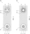
- radiation detector assembly 16 may include multiple radiation detectors 17 arranged radially within radiation detector assembly 16. In some embodiments, such as depicted in FIGS. 4 and 5 , radiation detector assembly 16 may detect radiation in all directions inside second wellbore 20 using multiple azimuthally sensitive radiation detectors 17. In certain embodiments, radiation detector assembly 16 may include between 3 and 20 radiation detectors 17. In certain embodiments, determination of the direction and range to first wellbore 10 may not require rotation of radiation detector assembly 16. Instead, radiation measurements made by each radiation detector 17 may be compared to determine the direction and range to first wellbore 10.
- radiation source 14 and radiation detector 17 may be depth aligned. Depth alignment may be accomplished by deploying radiation source 14 at a depth that minimizes the radial distance between radiation source 14 and radiation detector 17. In two adjacent vertical wellbores, the depth alignment may be accomplished by lowering radiation source 14 and radiation detector 17 so that radiation source 14 and radiation detector 17 are at approximately the same vertical depth. For nominally vertical wellbores, depths for alignment may be generally known based on prior wellbore surveys and may be predetermined before deploying radiation source 14 and radiation detector 17.
- the depth of radiation source 14 or radiation detector 17 may be varied until the magnitude of radiation detected by radiation detector 17 is sufficiently larger than background radiation or has sufficient performance statistics to begin the remainder of the nuclear ranging process to determine the direction between the wellbores. In some embodiments, if sufficient radiation magnitude is not detected by radiation detector 17 during the depth alignment process, varying of radiation source 14 or radiation detector 17 may be used to determine the minimum distance between the two wellbores at either the depth of radiation source 14 or radiation detector 17.
- one or more measurements may be taken by radiation detector 17. If radiation detector 17 is azimuthally sensitive, one or more radiation detector measurements may be obtained at different radial orientations by rotating the detector about its roll axis. If radiation source 14 is radially shielded, one or more radiation detector measurements may be obtained at different radial orientations by rotating radiation source 14 about its roll axis.
- the radial orientation of the azimuthally-sensitive radiation detector 17 and/or the radially-shielded radiation source 14 is determined by measuring a gyroscopic azimuth, gyro toolface, high-side toolface using accelerometers, and/or a magnetic azimuth or toolface using sensors associated with radiation detector 17 and/or radiation source 14.
- a response function or mapping may be created between the one or more radiation detector 17 measurements and the corresponding roll-axis measurements.
- the response function may be used as an indicator of the direction to a target.
- the roll-axis orientation corresponding to the highest detected radiation magnitude may be an indicator of the heading from one wellbore to the other wellbore.
- the response function may be interpolated or used in conjunction with a simulated or mathematical response model to obtain better resolution or accuracy on the relative heading.
- the response function may be used with a simulated or mathematical response model to also estimate the distance to the target.
- radiation detector 17 and roll axis measurements may be taken while either the radially-shielded radiation source and/or the azimuthally sensitivity are continuously rotated and then dynamically binned into sectored azimuthal measurements.
- the measurements may be obtained at discrete roll stationary axis orientations.
- azimuthally-sensitive radiation detector 17 and/or radially-shielded radiation source 14 may be oriented downhole to other drilling equipment, including but not limited to, a drilling assembly, whipstock, wireline or memory gyro, or a gyro MWD system. In some embodiments, azimuthally-sensitive radiation detector 17 and/or radially-shielded radiation source 14 may be deployed in a BHA that may be connected to a drilling or whipstock assembly.
- azimuthally-sensitive radiation detector 17 and/or the radially-shielded radiation source 14 may be deployed, mechanized platforms that allow for azimuthally-sensitive radiation detector 17 and/or the radially-shielded radiation source 14 to be rotated downhole.
- data regarding the direction of and magnitude readings from radiation detector 17 may be communicated by radiation detector 17 to surface by telemetry methods.
- data regarding the direction of the radially-shielded radiation source may be communicated from radiation source 14 to surface by telemetry methods.
- Telemetry methods may include, but are not limited to, electromagnetic telemetry, acoustic telemetry, mud pulse telemetry, wired pipe, or wireline communications.
- the influence of background radiation may be mapped and influence removed by turning radiation source 14 off, then performing the same measurements with radiation source 14 on.
- the orientation corresponding to the highest radiation magnitude may be an indicator of the heading from the target well toward the offset wellbore.
- radiation detector 17 instead of rotating a focused radiation detector, such as an azimuthally-focused radiation detector, radiation detector 17 may be displaced from one radial location to another radial location at the same depth in the wellbore, thereby changing the radial distance to the target wellbore and also correspondingly increasing or decreasing the amount of borehole fluid 11 between the radiation detector 17 and radiation source 14.
- the change in measured radiation at these positions may be a function of the radial proximity to the radiation and the attenuation along a travel path.
- the direction to first wellbore 10 may be determined.
- Radiation source 14 and radiation detector 17 are positioned in first wellbore 10 and second wellbore 20.
- the position of radiation source 14 in first wellbore 10 and radiation detector 17 in second wellbore 20 may be accomplished using the depth alignment procedure described herein above.
- one or both of radiation source 14 and radiation detector 17 are positioned at predetermined positions in first wellbore 10 and second wellbore 20.
- radiation source 14 may be activated, such as for a pulsed neutron generator. Where radiation source 14 is a natural neutron source or a natural gamma source, radiation source 14 may need not be activated. Radiation detector 17 may be activated.
- radiation source 14 may be rotated.
- radiation detector 17 may be rotated.
- radiation data may be acquired in a series of orientations. The orientation in which the highest radiation is detected may be considered the direction to the first wellbore.
- neither radiation source 14 nor radiation detector 17 are rotated.
- radiation source 14 may be cycled off and on, or removed from the first wellbore.
- the cycling or removal from the first wellbore of radiation source 14 may be accomplished to confirm that the radiation being detected by the focused radiation detector is from radiation source 14.
- the orientation of radiation detector 17 may be measured by using an azimuth sensor that is configured to measure the sensitive azimuth of the focused radiation detector, for example, a gyroscope, or some other action may be taken, e.g. a whipstock may be set, which may be dependent on the orientation of radiation detector 17.
- Radiation detector 17 may be coupled to the azimuth sensor.
- data regarding the direction of radiation detector 17 relative to radiation source 14 may be communicated from radiation detector 17 to the surface by telemetry methods. Telemetry methods may include, but are not limited to, EMF transmission, acoustic transmission, or mud pulse.
Landscapes
- Physics & Mathematics (AREA)
- Engineering & Computer Science (AREA)
- Life Sciences & Earth Sciences (AREA)
- Geology (AREA)
- Mining & Mineral Resources (AREA)
- Environmental & Geological Engineering (AREA)
- General Life Sciences & Earth Sciences (AREA)
- Geochemistry & Mineralogy (AREA)
- Geophysics (AREA)
- Fluid Mechanics (AREA)
- Geophysics And Detection Of Objects (AREA)
- Measurement Of Radiation (AREA)
- Remote Sensing (AREA)
- High Energy & Nuclear Physics (AREA)
- General Physics & Mathematics (AREA)
- Radar, Positioning & Navigation (AREA)
- Chemical & Material Sciences (AREA)
- Analytical Chemistry (AREA)
- Biochemistry (AREA)
- General Health & Medical Sciences (AREA)
- Immunology (AREA)
- Pathology (AREA)
- Health & Medical Sciences (AREA)
- Computer Networks & Wireless Communication (AREA)
- Analysing Materials By The Use Of Radiation (AREA)
Claims (14)
- Ortungs- und Näherungserfassungssystem (100), umfassend:eine Strahlungsquelle (14), wobei die Strahlungsquelle (14) innerhalb eines ersten Bohrlochs (10) positioniert ist, wobei die Strahlungsquelle (14) eine Quelle ionisierender Strahlung ist, wobei die Strahlungsquelle (14) innerhalb einer Strahlungsquellenanordnung (21) positioniert ist;einen Strahlungsdetektor (17), der innerhalb eines zweiten Bohrlochs (20) positioniert ist, wobei der Strahlungsdetektor (17) dazu eingerichtet ist, Strahlung von der Strahlungsquelle (14) zu erfassen, wobei der Strahlungsdetektor (17) innerhalb einer Strahlungsdetektoranordnung (16) positioniert ist;wobei das Ortungs- und Näherungserfassungssystem (100) dazu eingerichtet ist, den Abstand, die Richtung oder eine Kombination davon zwischen dem Strahlungsdetektor (17) und der Strahlungsquelle (14) zu bestimmen; unddadurch gekennzeichnet, dass die Strahlungsquelle (14), der Strahlungsdetektor (17) oder beide abgeschirmt sind.
- Ortungs- und Näherungserfassungssystem (100) nach Anspruch 1,wobei der Strahlungsdetektor (17), die Strahlungsquelle (14) oder beide durch ein Bohrungsfluid (11) abgeschirmt sind oderwobei die Strahlungsabschirmung atomar leichtes Kernmaterial ist.
- Ortungs- und Näherungserfassungssystem (100) nach Anspruch 1 oder Anspruch 2, wobei die Strahlungsquelle (14) eine Neutronenquelle ist und ein Schirm nahe der Strahlungsquelle (14) positioniert ist.
- Ortungs- und Näherungserfassungssystem (100) nach einem der Ansprüche 1 bis 3, wobei:die Strahlungsquelle (14) eine Neutronenquelle ist undder Strahlungsdetektor (17) ein Gammastrahlungsdetektor ist;wobei der Gammastrahlungsdetektor dazu eingerichtet ist, Gammastrahlung aus Strahlung von einer neutronenaktivierten Gammastrahlungsformation oder Bohrlochfluiden, die aus Neutronenstrahlung von der Neutronenquelle resultiert, zu erfassen;wobei das Ortungs- und Näherungserfassungssystem (100) dazu eingerichtet ist, den Abstand, die Richtung oder eine Kombination davon zwischen dem Gammastrahlungsdetektor und der Neutronenquelle zu bestimmen; undwobei der Gammastrahlungsdetektor azimutal empfindlich ist.
- Ortungs- und Näherungserfassungssystem (100) nach Anspruch 4, wobei die Neutronenquelle, der Gammastrahlungsdetektor oder beide radial abgeschirmt sind.
- Ortungs- und Näherungserfassungssystem (100) nach Anspruch 5, wobei die Strahlungsabschirmung atomar leichtes Kernmaterial oder ein Bohrungsfluid (11) ist.
- Ortungs- und Näherungserfassungssystem (100) nach Anspruch 5, wobei die Neutronenquelle von einer Mittellinie des ersten Bohrlochs (10) versetzt ist und der Versatz eine Abschirmung unter Verwendung eines Bohrungsfluids (11) bereitstellt.
- Verfahren, umfassend:Positionieren einer Strahlungsquelle (14) innerhalb eines ersten Bohrlochs (10) und einer Strahlungsquellenanordnung (21), wobei die Strahlungsquelle (14) eine Quelle ionisierender Strahlung ist;Positionieren eines Strahlungsdetektors (17) innerhalb eines zweiten Bohrlochs (20) und einer Strahlungsdetektoranordnung (21), wobei der Strahlungsdetektor (17) dazu eingerichtet ist, Strahlung von der Strahlungsquelle (14) zu erfassen;Abschirmen der Strahlungsquelle (14), des Strahlungsdetektors (17) oder beider;Erfassen von Strahlung, die von der Strahlungsquelle (14) emittiert wird, mit dem Strahlungsdetektor (17) undBestimmen des Abstands, der Richtung oder einer Kombination davon zwischen dem Strahlungsdetektor (17) und der Strahlungsquelle (14).
- Verfahren nach Anspruch 8, weiterhin umfassend ein Verwenden eines gyroskopischen Azimuts, Kreisel-Toolfaces, High-Side-Toolfaces, magnetisches Azimuts oder magnetischen Toolfaces oder einer Kombination davon, um die Ausrichtung der Strahlungsquelle (14), des Strahlungsdetektors (17) oder einer Kombination davon zu messen.
- Verfahren nach Anspruch 8, wobei, wenn die Position der Strahlungsquelle von einer Mittellinie des ersten Bohrlochs versetzt wird, die Menge eines Bohrungsfluids zwischen der Strahlungsquelle und dem ersten Bohrloch radial in Bezug auf die Strahlungsquelle variiert.
- Verfahren nach Anspruch 8, wobei die Strahlungsquelle (14) eine Neutronenquelle ist und die Neutronenquelle (14) eine radial abgeschirmte Quelle ist, wobei das Verfahren weiterhin die Schritte umfasst: Bestimmen der Richtung zu dem zweiten Bohrloch (20) von dem ersten Bohrloch (10) durch Messen der erfassten Strahlung und der Ausrichtung der radial abgeschirmten Quelle und
Erfassen von neutronenaktivierter Gammastrahlung aus Strahlung von einer neutronenaktivierten Formation oder Bohrungsfluiden, die aus Neutronenstrahlung von der Neutronenquelle resultiert. - Verfahren nach Anspruch 11, wobei der Schritt des Bestimmens der Richtung zu dem zweiten Bohrloch (20) von dem ersten Bohrloch (10) weiterhin ein Bestimmen der Ausrichtung, in der die höchste Strahlungsgrößenordnung von dem Strahlungsdetektor (17) erfasst wird, umfasst.
- Verfahren nach Anspruch 12, weiterhin umfassend ein Ändern der Menge an Bohrungsfluid (11) zwischen dem Strahlungsdetektor (17) und der radial abgeschirmten Quelle, um die eine oder die mehreren radial abgeschirmten Quellen radial abgeschirmt zu machen.
- Verfahren nach Anspruch 11, wobei, wenn die Ausrichtung der Neutronenquelle, des Strahlungsdetektors (17) oder beider geändert wird, die erfasste Strahlung durch Ändern der Menge an Bohrungsfluid (10) zwischen dem Strahlungsdetektor (17) und der Neutronenquelle variiert wird.
Priority Applications (1)
| Application Number | Priority Date | Filing Date | Title |
|---|---|---|---|
| EP24163455.9A EP4361395B1 (de) | 2016-05-09 | 2017-05-09 | Verfahren zur bohrlochmessung und näherungserkennung |
Applications Claiming Priority (3)
| Application Number | Priority Date | Filing Date | Title |
|---|---|---|---|
| US201662333661P | 2016-05-09 | 2016-05-09 | |
| PCT/US2017/031790 WO2017196866A1 (en) | 2016-05-09 | 2017-05-09 | Method for wellbore ranging and proximity detection |
| EP17796701.5A EP3455461B1 (de) | 2016-05-09 | 2017-05-09 | Verfahren zur bohrlochmessung und näherungserkennung |
Related Parent Applications (1)
| Application Number | Title | Priority Date | Filing Date |
|---|---|---|---|
| EP17796701.5A Division EP3455461B1 (de) | 2016-05-09 | 2017-05-09 | Verfahren zur bohrlochmessung und näherungserkennung |
Related Child Applications (1)
| Application Number | Title | Priority Date | Filing Date |
|---|---|---|---|
| EP24163455.9A Division EP4361395B1 (de) | 2016-05-09 | 2017-05-09 | Verfahren zur bohrlochmessung und näherungserkennung |
Publications (2)
| Publication Number | Publication Date |
|---|---|
| EP4141216A1 EP4141216A1 (de) | 2023-03-01 |
| EP4141216B1 true EP4141216B1 (de) | 2024-04-10 |
Family
ID=60243846
Family Applications (3)
| Application Number | Title | Priority Date | Filing Date |
|---|---|---|---|
| EP22202206.3A Active EP4141216B1 (de) | 2016-05-09 | 2017-05-09 | Verfahren zur bohrlochmessung und näherungserkennung |
| EP17796701.5A Active EP3455461B1 (de) | 2016-05-09 | 2017-05-09 | Verfahren zur bohrlochmessung und näherungserkennung |
| EP24163455.9A Active EP4361395B1 (de) | 2016-05-09 | 2017-05-09 | Verfahren zur bohrlochmessung und näherungserkennung |
Family Applications After (2)
| Application Number | Title | Priority Date | Filing Date |
|---|---|---|---|
| EP17796701.5A Active EP3455461B1 (de) | 2016-05-09 | 2017-05-09 | Verfahren zur bohrlochmessung und näherungserkennung |
| EP24163455.9A Active EP4361395B1 (de) | 2016-05-09 | 2017-05-09 | Verfahren zur bohrlochmessung und näherungserkennung |
Country Status (4)
| Country | Link |
|---|---|
| US (1) | US10731456B2 (de) |
| EP (3) | EP4141216B1 (de) |
| CA (1) | CA3021666A1 (de) |
| WO (1) | WO2017196866A1 (de) |
Families Citing this family (2)
| Publication number | Priority date | Publication date | Assignee | Title |
|---|---|---|---|---|
| CA3089808C (en) * | 2018-03-06 | 2022-08-02 | Halliburton Energy Services, Inc. | Determining a relative wellbore location utilizing a well shoe having a ranging source |
| US11359481B2 (en) * | 2019-11-05 | 2022-06-14 | Halliburton Energy Services, Inc. | Indicating position of a moving mechanism of well site tools |
Family Cites Families (22)
| Publication number | Priority date | Publication date | Assignee | Title |
|---|---|---|---|---|
| US5481105A (en) * | 1993-06-04 | 1996-01-02 | Halliburton Company | Neutron backscatter gravel pack logging sonde with azimuthal scan capability |
| US6552333B1 (en) * | 2000-08-16 | 2003-04-22 | Halliburton Energy Services, Inc. | Apparatus and methods for determining gravel pack quality |
| US20060042792A1 (en) | 2004-08-24 | 2006-03-02 | Connell Michael L | Methods and apparatus for locating a lateral wellbore |
| US8026722B2 (en) * | 2004-12-20 | 2011-09-27 | Smith International, Inc. | Method of magnetizing casing string tubulars for enhanced passive ranging |
| US7339161B2 (en) * | 2005-02-24 | 2008-03-04 | Schlumberger Technology Corporation | Shielded pads for detecting subsurface radiation phenomena |
| US7351982B2 (en) * | 2005-05-24 | 2008-04-01 | Washington Savannah River Company Llp | Portable nuclear material detector and process |
| EP1732085A1 (de) * | 2005-06-10 | 2006-12-13 | Atomic Energy Council - Institute of Nuclear Energy Research | Vorrichtung und Verfahren zur zerstörungsfreien Prüfung mittels Neutronenrückstreuung |
| US9030911B2 (en) * | 2007-12-07 | 2015-05-12 | Baker Hughes Incorporated | Method and system for delineating a second wellbore from a first wellbore |
| US9322262B2 (en) * | 2011-12-22 | 2016-04-26 | Schlumberger Technology Corporation | Pulsed neutron generator tube design which extends the lifetime of a cathode |
| US8912484B2 (en) * | 2012-03-28 | 2014-12-16 | Schlumberger Technology Corporation | Photomultipler-based neutron detector |
| EP2741110A1 (de) * | 2012-12-06 | 2014-06-11 | Services Pétroliers Schlumberger | Gasgefüllter Bohrlochstrahlungsdetektor mit Lichtleiter |
| WO2014131132A1 (en) * | 2013-03-01 | 2014-09-04 | Xact Downhole Telemetry Inc. | Range positioning tool for use within a casing or liner string |
| WO2014179420A2 (en) * | 2013-04-30 | 2014-11-06 | Schlumberger Canada Limited | Compensated sigma calculation based on pulsed neutron capture tool meaurements |
| US9885802B2 (en) * | 2013-10-01 | 2018-02-06 | Baker Hughes, A Ge Company, Llc | Downhole cement evalution using pulsed neutron measurements |
| AU2013405143B2 (en) * | 2013-11-14 | 2017-03-16 | Halliburton Energy Services, Inc. | Method and apparatus for ranging to a nearby well from ahead of a drill bit |
| GB2526109A (en) * | 2014-05-14 | 2015-11-18 | Symetrica Ltd | Neutron detection |
| US10161237B2 (en) * | 2014-07-25 | 2018-12-25 | Carbo Ceramics Inc. | Identification of proppant in subterranean fracture zones using a ratio of capture to inelastic gamma rays |
| US10273799B2 (en) * | 2014-08-11 | 2019-04-30 | Halliburton Energy Services, Inc. | Well ranging apparatus, systems, and methods |
| US9482562B2 (en) * | 2015-03-27 | 2016-11-01 | General Electric Company | Shielded radiation detector heads |
| AU2015414738B2 (en) * | 2015-11-17 | 2021-01-14 | Halliburton Energy Services, Inc. | One-trip multilateral tool |
| US9702990B2 (en) * | 2015-11-18 | 2017-07-11 | Weatherford Technology Holdings, Llc | Gain stabilization of radiation detectors via spectrum analysis |
| EP3181807A1 (de) * | 2015-12-18 | 2017-06-21 | Services Pétroliers Schlumberger | Bohrlochwerkzeug und verfahren zur abbildung eines bohrlochs |
-
2017
- 2017-05-09 EP EP22202206.3A patent/EP4141216B1/de active Active
- 2017-05-09 EP EP17796701.5A patent/EP3455461B1/de active Active
- 2017-05-09 EP EP24163455.9A patent/EP4361395B1/de active Active
- 2017-05-09 US US15/590,834 patent/US10731456B2/en active Active
- 2017-05-09 WO PCT/US2017/031790 patent/WO2017196866A1/en not_active Ceased
- 2017-05-09 CA CA3021666A patent/CA3021666A1/en not_active Abandoned
Also Published As
| Publication number | Publication date |
|---|---|
| EP4141216A1 (de) | 2023-03-01 |
| US20170321539A1 (en) | 2017-11-09 |
| EP4361395B1 (de) | 2025-11-26 |
| CA3021666A1 (en) | 2017-11-16 |
| EP3455461A1 (de) | 2019-03-20 |
| WO2017196866A1 (en) | 2017-11-16 |
| EP4361395A3 (de) | 2024-07-31 |
| EP4361395A2 (de) | 2024-05-01 |
| US10731456B2 (en) | 2020-08-04 |
| EP3455461A4 (de) | 2020-01-01 |
| EP3455461B1 (de) | 2022-11-09 |
Similar Documents
| Publication | Publication Date | Title |
|---|---|---|
| EP2561182B1 (de) | Formationsevaluierung mit einer bit-basierten aktiven strahlungsquelle und einem gammastrahlendetektor | |
| US9012836B2 (en) | Neutron logging tool with multiple detectors | |
| CN105874354B (zh) | 用于进行井下测量的系统和方法 | |
| US10101493B2 (en) | Method for correcting natural gamma ray logging measurements | |
| US10920568B2 (en) | Evaluating cement integrity in a wellbore with multiple casing strings | |
| EA010781B1 (ru) | Комплексное каротажное устройство для буровой скважины | |
| US20200096668A1 (en) | Methods and means for azimuthal neutron porosity imaging of formation and cement volumes surrounding a borehole | |
| EP4141216B1 (de) | Verfahren zur bohrlochmessung und näherungserkennung | |
| US9823384B1 (en) | Mud activation measurement while drilling | |
| CN104823076B (zh) | 用于检测地下岩层中的断口的方法 | |
| US11275195B2 (en) | Methods and means for azimuthal neutron porosity imaging of formation and cement volumes surrounding a borehole |
Legal Events
| Date | Code | Title | Description |
|---|---|---|---|
| PUAI | Public reference made under article 153(3) epc to a published international application that has entered the european phase |
Free format text: ORIGINAL CODE: 0009012 |
|
| STAA | Information on the status of an ep patent application or granted ep patent |
Free format text: STATUS: THE APPLICATION HAS BEEN PUBLISHED |
|
| AC | Divisional application: reference to earlier application |
Ref document number: 3455461 Country of ref document: EP Kind code of ref document: P |
|
| AK | Designated contracting states |
Kind code of ref document: A1 Designated state(s): AL AT BE BG CH CY CZ DE DK EE ES FI FR GB GR HR HU IE IS IT LI LT LU LV MC MK MT NL NO PL PT RO RS SE SI SK SM TR |
|
| STAA | Information on the status of an ep patent application or granted ep patent |
Free format text: STATUS: REQUEST FOR EXAMINATION WAS MADE |
|
| 17P | Request for examination filed |
Effective date: 20230330 |
|
| RBV | Designated contracting states (corrected) |
Designated state(s): AL AT BE BG CH CY CZ DE DK EE ES FI FR GB GR HR HU IE IS IT LI LT LU LV MC MK MT NL NO PL PT RO RS SE SI SK SM TR |
|
| GRAP | Despatch of communication of intention to grant a patent |
Free format text: ORIGINAL CODE: EPIDOSNIGR1 |
|
| STAA | Information on the status of an ep patent application or granted ep patent |
Free format text: STATUS: GRANT OF PATENT IS INTENDED |
|
| INTG | Intention to grant announced |
Effective date: 20240123 |
|
| GRAS | Grant fee paid |
Free format text: ORIGINAL CODE: EPIDOSNIGR3 |
|
| GRAA | (expected) grant |
Free format text: ORIGINAL CODE: 0009210 |
|
| STAA | Information on the status of an ep patent application or granted ep patent |
Free format text: STATUS: THE PATENT HAS BEEN GRANTED |
|
| AC | Divisional application: reference to earlier application |
Ref document number: 3455461 Country of ref document: EP Kind code of ref document: P |
|
| AK | Designated contracting states |
Kind code of ref document: B1 Designated state(s): AL AT BE BG CH CY CZ DE DK EE ES FI FR GB GR HR HU IE IS IT LI LT LU LV MC MK MT NL NO PL PT RO RS SE SI SK SM TR |
|
| REG | Reference to a national code |
Ref country code: GB Ref legal event code: FG4D |
|
| REG | Reference to a national code |
Ref country code: CH Ref legal event code: EP |
|
| REG | Reference to a national code |
Ref country code: DE Ref legal event code: R096 Ref document number: 602017081026 Country of ref document: DE |
|
| P01 | Opt-out of the competence of the unified patent court (upc) registered |
Effective date: 20240321 |
|
| REG | Reference to a national code |
Ref country code: IE Ref legal event code: FG4D |
|
| REG | Reference to a national code |
Ref country code: LT Ref legal event code: MG9D |
|
| REG | Reference to a national code |
Ref country code: NL Ref legal event code: MP Effective date: 20240410 |
|
| REG | Reference to a national code |
Ref country code: AT Ref legal event code: MK05 Ref document number: 1675093 Country of ref document: AT Kind code of ref document: T Effective date: 20240410 |
|
| PG25 | Lapsed in a contracting state [announced via postgrant information from national office to epo] |
Ref country code: NL Free format text: LAPSE BECAUSE OF FAILURE TO SUBMIT A TRANSLATION OF THE DESCRIPTION OR TO PAY THE FEE WITHIN THE PRESCRIBED TIME-LIMIT Effective date: 20240410 |
|
| PG25 | Lapsed in a contracting state [announced via postgrant information from national office to epo] |
Ref country code: NL Free format text: LAPSE BECAUSE OF FAILURE TO SUBMIT A TRANSLATION OF THE DESCRIPTION OR TO PAY THE FEE WITHIN THE PRESCRIBED TIME-LIMIT Effective date: 20240410 |
|
| PG25 | Lapsed in a contracting state [announced via postgrant information from national office to epo] |
Ref country code: IS Free format text: LAPSE BECAUSE OF FAILURE TO SUBMIT A TRANSLATION OF THE DESCRIPTION OR TO PAY THE FEE WITHIN THE PRESCRIBED TIME-LIMIT Effective date: 20240810 |
|
| PG25 | Lapsed in a contracting state [announced via postgrant information from national office to epo] |
Ref country code: BG Free format text: LAPSE BECAUSE OF FAILURE TO SUBMIT A TRANSLATION OF THE DESCRIPTION OR TO PAY THE FEE WITHIN THE PRESCRIBED TIME-LIMIT Effective date: 20240410 |
|
| PG25 | Lapsed in a contracting state [announced via postgrant information from national office to epo] |
Ref country code: FI Free format text: LAPSE BECAUSE OF FAILURE TO SUBMIT A TRANSLATION OF THE DESCRIPTION OR TO PAY THE FEE WITHIN THE PRESCRIBED TIME-LIMIT Effective date: 20240410 Ref country code: HR Free format text: LAPSE BECAUSE OF FAILURE TO SUBMIT A TRANSLATION OF THE DESCRIPTION OR TO PAY THE FEE WITHIN THE PRESCRIBED TIME-LIMIT Effective date: 20240410 |
|
| PG25 | Lapsed in a contracting state [announced via postgrant information from national office to epo] |
Ref country code: GR Free format text: LAPSE BECAUSE OF FAILURE TO SUBMIT A TRANSLATION OF THE DESCRIPTION OR TO PAY THE FEE WITHIN THE PRESCRIBED TIME-LIMIT Effective date: 20240711 |
|
| PG25 | Lapsed in a contracting state [announced via postgrant information from national office to epo] |
Ref country code: PT Free format text: LAPSE BECAUSE OF FAILURE TO SUBMIT A TRANSLATION OF THE DESCRIPTION OR TO PAY THE FEE WITHIN THE PRESCRIBED TIME-LIMIT Effective date: 20240812 |
|
| PG25 | Lapsed in a contracting state [announced via postgrant information from national office to epo] |
Ref country code: ES Free format text: LAPSE BECAUSE OF FAILURE TO SUBMIT A TRANSLATION OF THE DESCRIPTION OR TO PAY THE FEE WITHIN THE PRESCRIBED TIME-LIMIT Effective date: 20240410 |
|
| PG25 | Lapsed in a contracting state [announced via postgrant information from national office to epo] |
Ref country code: AT Free format text: LAPSE BECAUSE OF FAILURE TO SUBMIT A TRANSLATION OF THE DESCRIPTION OR TO PAY THE FEE WITHIN THE PRESCRIBED TIME-LIMIT Effective date: 20240410 |
|
| PG25 | Lapsed in a contracting state [announced via postgrant information from national office to epo] |
Ref country code: PL Free format text: LAPSE BECAUSE OF FAILURE TO SUBMIT A TRANSLATION OF THE DESCRIPTION OR TO PAY THE FEE WITHIN THE PRESCRIBED TIME-LIMIT Effective date: 20240410 |
|
| PG25 | Lapsed in a contracting state [announced via postgrant information from national office to epo] |
Ref country code: LV Free format text: LAPSE BECAUSE OF FAILURE TO SUBMIT A TRANSLATION OF THE DESCRIPTION OR TO PAY THE FEE WITHIN THE PRESCRIBED TIME-LIMIT Effective date: 20240410 |
|
| PG25 | Lapsed in a contracting state [announced via postgrant information from national office to epo] |
Ref country code: PT Free format text: LAPSE BECAUSE OF FAILURE TO SUBMIT A TRANSLATION OF THE DESCRIPTION OR TO PAY THE FEE WITHIN THE PRESCRIBED TIME-LIMIT Effective date: 20240812 Ref country code: PL Free format text: LAPSE BECAUSE OF FAILURE TO SUBMIT A TRANSLATION OF THE DESCRIPTION OR TO PAY THE FEE WITHIN THE PRESCRIBED TIME-LIMIT Effective date: 20240410 Ref country code: LV Free format text: LAPSE BECAUSE OF FAILURE TO SUBMIT A TRANSLATION OF THE DESCRIPTION OR TO PAY THE FEE WITHIN THE PRESCRIBED TIME-LIMIT Effective date: 20240410 Ref country code: IS Free format text: LAPSE BECAUSE OF FAILURE TO SUBMIT A TRANSLATION OF THE DESCRIPTION OR TO PAY THE FEE WITHIN THE PRESCRIBED TIME-LIMIT Effective date: 20240810 Ref country code: HR Free format text: LAPSE BECAUSE OF FAILURE TO SUBMIT A TRANSLATION OF THE DESCRIPTION OR TO PAY THE FEE WITHIN THE PRESCRIBED TIME-LIMIT Effective date: 20240410 Ref country code: GR Free format text: LAPSE BECAUSE OF FAILURE TO SUBMIT A TRANSLATION OF THE DESCRIPTION OR TO PAY THE FEE WITHIN THE PRESCRIBED TIME-LIMIT Effective date: 20240711 Ref country code: FI Free format text: LAPSE BECAUSE OF FAILURE TO SUBMIT A TRANSLATION OF THE DESCRIPTION OR TO PAY THE FEE WITHIN THE PRESCRIBED TIME-LIMIT Effective date: 20240410 Ref country code: ES Free format text: LAPSE BECAUSE OF FAILURE TO SUBMIT A TRANSLATION OF THE DESCRIPTION OR TO PAY THE FEE WITHIN THE PRESCRIBED TIME-LIMIT Effective date: 20240410 Ref country code: BG Free format text: LAPSE BECAUSE OF FAILURE TO SUBMIT A TRANSLATION OF THE DESCRIPTION OR TO PAY THE FEE WITHIN THE PRESCRIBED TIME-LIMIT Effective date: 20240410 Ref country code: AT Free format text: LAPSE BECAUSE OF FAILURE TO SUBMIT A TRANSLATION OF THE DESCRIPTION OR TO PAY THE FEE WITHIN THE PRESCRIBED TIME-LIMIT Effective date: 20240410 Ref country code: RS Free format text: LAPSE BECAUSE OF FAILURE TO SUBMIT A TRANSLATION OF THE DESCRIPTION OR TO PAY THE FEE WITHIN THE PRESCRIBED TIME-LIMIT Effective date: 20240710 |
|
| REG | Reference to a national code |
Ref country code: DE Ref legal event code: R119 Ref document number: 602017081026 Country of ref document: DE |
|
| REG | Reference to a national code |
Ref country code: CH Ref legal event code: PL |
|
| PG25 | Lapsed in a contracting state [announced via postgrant information from national office to epo] |
Ref country code: DK Free format text: LAPSE BECAUSE OF FAILURE TO SUBMIT A TRANSLATION OF THE DESCRIPTION OR TO PAY THE FEE WITHIN THE PRESCRIBED TIME-LIMIT Effective date: 20240410 |
|
| PG25 | Lapsed in a contracting state [announced via postgrant information from national office to epo] |
Ref country code: LU Free format text: LAPSE BECAUSE OF NON-PAYMENT OF DUE FEES Effective date: 20240509 |
|
| PG25 | Lapsed in a contracting state [announced via postgrant information from national office to epo] |
Ref country code: EE Free format text: LAPSE BECAUSE OF FAILURE TO SUBMIT A TRANSLATION OF THE DESCRIPTION OR TO PAY THE FEE WITHIN THE PRESCRIBED TIME-LIMIT Effective date: 20240410 |
|
| PG25 | Lapsed in a contracting state [announced via postgrant information from national office to epo] |
Ref country code: CZ Free format text: LAPSE BECAUSE OF FAILURE TO SUBMIT A TRANSLATION OF THE DESCRIPTION OR TO PAY THE FEE WITHIN THE PRESCRIBED TIME-LIMIT Effective date: 20240410 |
|
| PG25 | Lapsed in a contracting state [announced via postgrant information from national office to epo] |
Ref country code: SK Free format text: LAPSE BECAUSE OF FAILURE TO SUBMIT A TRANSLATION OF THE DESCRIPTION OR TO PAY THE FEE WITHIN THE PRESCRIBED TIME-LIMIT Effective date: 20240410 Ref country code: RO Free format text: LAPSE BECAUSE OF FAILURE TO SUBMIT A TRANSLATION OF THE DESCRIPTION OR TO PAY THE FEE WITHIN THE PRESCRIBED TIME-LIMIT Effective date: 20240410 |
|
| PG25 | Lapsed in a contracting state [announced via postgrant information from national office to epo] |
Ref country code: SM Free format text: LAPSE BECAUSE OF FAILURE TO SUBMIT A TRANSLATION OF THE DESCRIPTION OR TO PAY THE FEE WITHIN THE PRESCRIBED TIME-LIMIT Effective date: 20240410 |
|
| PG25 | Lapsed in a contracting state [announced via postgrant information from national office to epo] |
Ref country code: SM Free format text: LAPSE BECAUSE OF FAILURE TO SUBMIT A TRANSLATION OF THE DESCRIPTION OR TO PAY THE FEE WITHIN THE PRESCRIBED TIME-LIMIT Effective date: 20240410 Ref country code: SK Free format text: LAPSE BECAUSE OF FAILURE TO SUBMIT A TRANSLATION OF THE DESCRIPTION OR TO PAY THE FEE WITHIN THE PRESCRIBED TIME-LIMIT Effective date: 20240410 Ref country code: RO Free format text: LAPSE BECAUSE OF FAILURE TO SUBMIT A TRANSLATION OF THE DESCRIPTION OR TO PAY THE FEE WITHIN THE PRESCRIBED TIME-LIMIT Effective date: 20240410 Ref country code: LU Free format text: LAPSE BECAUSE OF NON-PAYMENT OF DUE FEES Effective date: 20240509 Ref country code: EE Free format text: LAPSE BECAUSE OF FAILURE TO SUBMIT A TRANSLATION OF THE DESCRIPTION OR TO PAY THE FEE WITHIN THE PRESCRIBED TIME-LIMIT Effective date: 20240410 Ref country code: DK Free format text: LAPSE BECAUSE OF FAILURE TO SUBMIT A TRANSLATION OF THE DESCRIPTION OR TO PAY THE FEE WITHIN THE PRESCRIBED TIME-LIMIT Effective date: 20240410 Ref country code: CZ Free format text: LAPSE BECAUSE OF FAILURE TO SUBMIT A TRANSLATION OF THE DESCRIPTION OR TO PAY THE FEE WITHIN THE PRESCRIBED TIME-LIMIT Effective date: 20240410 Ref country code: MC Free format text: LAPSE BECAUSE OF FAILURE TO SUBMIT A TRANSLATION OF THE DESCRIPTION OR TO PAY THE FEE WITHIN THE PRESCRIBED TIME-LIMIT Effective date: 20240410 Ref country code: CH Free format text: LAPSE BECAUSE OF NON-PAYMENT OF DUE FEES Effective date: 20240531 |
|
| PG25 | Lapsed in a contracting state [announced via postgrant information from national office to epo] |
Ref country code: IT Free format text: LAPSE BECAUSE OF FAILURE TO SUBMIT A TRANSLATION OF THE DESCRIPTION OR TO PAY THE FEE WITHIN THE PRESCRIBED TIME-LIMIT Effective date: 20240410 |
|
| PLBE | No opposition filed within time limit |
Free format text: ORIGINAL CODE: 0009261 |
|
| STAA | Information on the status of an ep patent application or granted ep patent |
Free format text: STATUS: NO OPPOSITION FILED WITHIN TIME LIMIT |
|
| REG | Reference to a national code |
Ref country code: BE Ref legal event code: MM Effective date: 20240531 |
|
| 26N | No opposition filed |
Effective date: 20250113 |
|
| PG25 | Lapsed in a contracting state [announced via postgrant information from national office to epo] |
Ref country code: DE Free format text: LAPSE BECAUSE OF NON-PAYMENT OF DUE FEES Effective date: 20241203 |
|
| PG25 | Lapsed in a contracting state [announced via postgrant information from national office to epo] |
Ref country code: IE Free format text: LAPSE BECAUSE OF NON-PAYMENT OF DUE FEES Effective date: 20240509 |
|
| PG25 | Lapsed in a contracting state [announced via postgrant information from national office to epo] |
Ref country code: SI Free format text: LAPSE BECAUSE OF FAILURE TO SUBMIT A TRANSLATION OF THE DESCRIPTION OR TO PAY THE FEE WITHIN THE PRESCRIBED TIME-LIMIT Effective date: 20240410 Ref country code: BE Free format text: LAPSE BECAUSE OF NON-PAYMENT OF DUE FEES Effective date: 20240531 |
|
| PG25 | Lapsed in a contracting state [announced via postgrant information from national office to epo] |
Ref country code: FR Free format text: LAPSE BECAUSE OF NON-PAYMENT OF DUE FEES Effective date: 20240610 |
|
| PGFP | Annual fee paid to national office [announced via postgrant information from national office to epo] |
Ref country code: GB Payment date: 20250512 Year of fee payment: 9 |
|
| PGFP | Annual fee paid to national office [announced via postgrant information from national office to epo] |
Ref country code: NO Payment date: 20250523 Year of fee payment: 9 |
|
| PG25 | Lapsed in a contracting state [announced via postgrant information from national office to epo] |
Ref country code: CY Free format text: LAPSE BECAUSE OF FAILURE TO SUBMIT A TRANSLATION OF THE DESCRIPTION OR TO PAY THE FEE WITHIN THE PRESCRIBED TIME-LIMIT; INVALID AB INITIO Effective date: 20170509 |
|
| PG25 | Lapsed in a contracting state [announced via postgrant information from national office to epo] |
Ref country code: HU Free format text: LAPSE BECAUSE OF FAILURE TO SUBMIT A TRANSLATION OF THE DESCRIPTION OR TO PAY THE FEE WITHIN THE PRESCRIBED TIME-LIMIT; INVALID AB INITIO Effective date: 20170509 |
|
| PG25 | Lapsed in a contracting state [announced via postgrant information from national office to epo] |
Ref country code: SE Free format text: LAPSE BECAUSE OF FAILURE TO SUBMIT A TRANSLATION OF THE DESCRIPTION OR TO PAY THE FEE WITHIN THE PRESCRIBED TIME-LIMIT Effective date: 20240410 |