EP4141229B1 - Chauffage à gaz d'échappement et procédé de fabrication d'un chauffage à gaz d'échappement - Google Patents
Chauffage à gaz d'échappement et procédé de fabrication d'un chauffage à gaz d'échappement Download PDFInfo
- Publication number
- EP4141229B1 EP4141229B1 EP22187407.6A EP22187407A EP4141229B1 EP 4141229 B1 EP4141229 B1 EP 4141229B1 EP 22187407 A EP22187407 A EP 22187407A EP 4141229 B1 EP4141229 B1 EP 4141229B1
- Authority
- EP
- European Patent Office
- Prior art keywords
- carrier
- arrangement
- exhaust gas
- heating conductor
- gas heater
- Prior art date
- Legal status (The legal status is an assumption and is not a legal conclusion. Google has not performed a legal analysis and makes no representation as to the accuracy of the status listed.)
- Active
Links
Images

Classifications
-
- H—ELECTRICITY
- H05—ELECTRIC TECHNIQUES NOT OTHERWISE PROVIDED FOR
- H05B—ELECTRIC HEATING; ELECTRIC LIGHT SOURCES NOT OTHERWISE PROVIDED FOR; CIRCUIT ARRANGEMENTS FOR ELECTRIC LIGHT SOURCES, IN GENERAL
- H05B3/00—Ohmic-resistance heating
- H05B3/10—Heating elements characterised by the composition or nature of the materials or by the arrangement of the conductor
- H05B3/16—Heating elements characterised by the composition or nature of the materials or by the arrangement of the conductor the conductor being mounted on an insulating base
-
- F—MECHANICAL ENGINEERING; LIGHTING; HEATING; WEAPONS; BLASTING
- F01—MACHINES OR ENGINES IN GENERAL; ENGINE PLANTS IN GENERAL; STEAM ENGINES
- F01N—GAS-FLOW SILENCERS OR EXHAUST APPARATUS FOR MACHINES OR ENGINES IN GENERAL; GAS-FLOW SILENCERS OR EXHAUST APPARATUS FOR INTERNAL-COMBUSTION ENGINES
- F01N3/00—Exhaust or silencing apparatus having means for purifying, rendering innocuous, or otherwise treating exhaust
- F01N3/08—Exhaust or silencing apparatus having means for purifying, rendering innocuous, or otherwise treating exhaust for rendering innocuous
- F01N3/10—Exhaust or silencing apparatus having means for purifying, rendering innocuous, or otherwise treating exhaust for rendering innocuous by thermal or catalytic conversion of noxious components of exhaust
- F01N3/18—Exhaust or silencing apparatus having means for purifying, rendering innocuous, or otherwise treating exhaust for rendering innocuous by thermal or catalytic conversion of noxious components of exhaust characterised by methods of operation; Control
- F01N3/20—Exhaust or silencing apparatus having means for purifying, rendering innocuous, or otherwise treating exhaust for rendering innocuous by thermal or catalytic conversion of noxious components of exhaust characterised by methods of operation; Control specially adapted for catalytic conversion
- F01N3/2006—Periodically heating or cooling catalytic reactors, e.g. at cold starting or overheating
- F01N3/2013—Periodically heating or cooling catalytic reactors, e.g. at cold starting or overheating using electric or magnetic heating means
-
- F—MECHANICAL ENGINEERING; LIGHTING; HEATING; WEAPONS; BLASTING
- F01—MACHINES OR ENGINES IN GENERAL; ENGINE PLANTS IN GENERAL; STEAM ENGINES
- F01N—GAS-FLOW SILENCERS OR EXHAUST APPARATUS FOR MACHINES OR ENGINES IN GENERAL; GAS-FLOW SILENCERS OR EXHAUST APPARATUS FOR INTERNAL-COMBUSTION ENGINES
- F01N3/00—Exhaust or silencing apparatus having means for purifying, rendering innocuous, or otherwise treating exhaust
- F01N3/02—Exhaust or silencing apparatus having means for purifying, rendering innocuous, or otherwise treating exhaust for cooling, or for removing solid constituents of, exhaust
- F01N3/021—Exhaust or silencing apparatus having means for purifying, rendering innocuous, or otherwise treating exhaust for cooling, or for removing solid constituents of, exhaust by means of filters
- F01N3/023—Exhaust or silencing apparatus having means for purifying, rendering innocuous, or otherwise treating exhaust for cooling, or for removing solid constituents of, exhaust by means of filters using means for regenerating the filters, e.g. by burning trapped particles
- F01N3/027—Exhaust or silencing apparatus having means for purifying, rendering innocuous, or otherwise treating exhaust for cooling, or for removing solid constituents of, exhaust by means of filters using means for regenerating the filters, e.g. by burning trapped particles using electric or magnetic heating means
-
- H—ELECTRICITY
- H05—ELECTRIC TECHNIQUES NOT OTHERWISE PROVIDED FOR
- H05B—ELECTRIC HEATING; ELECTRIC LIGHT SOURCES NOT OTHERWISE PROVIDED FOR; CIRCUIT ARRANGEMENTS FOR ELECTRIC LIGHT SOURCES, IN GENERAL
- H05B3/00—Ohmic-resistance heating
- H05B3/02—Details
- H05B3/06—Heater elements structurally combined with coupling elements or holders
-
- H—ELECTRICITY
- H05—ELECTRIC TECHNIQUES NOT OTHERWISE PROVIDED FOR
- H05B—ELECTRIC HEATING; ELECTRIC LIGHT SOURCES NOT OTHERWISE PROVIDED FOR; CIRCUIT ARRANGEMENTS FOR ELECTRIC LIGHT SOURCES, IN GENERAL
- H05B3/00—Ohmic-resistance heating
- H05B3/10—Heating elements characterised by the composition or nature of the materials or by the arrangement of the conductor
-
- F—MECHANICAL ENGINEERING; LIGHTING; HEATING; WEAPONS; BLASTING
- F01—MACHINES OR ENGINES IN GENERAL; ENGINE PLANTS IN GENERAL; STEAM ENGINES
- F01N—GAS-FLOW SILENCERS OR EXHAUST APPARATUS FOR MACHINES OR ENGINES IN GENERAL; GAS-FLOW SILENCERS OR EXHAUST APPARATUS FOR INTERNAL-COMBUSTION ENGINES
- F01N2240/00—Combination or association of two or more different exhaust treating devices, or of at least one such device with an auxiliary device, not covered by indexing codes F01N2230/00 or F01N2250/00, one of the devices being
- F01N2240/16—Combination or association of two or more different exhaust treating devices, or of at least one such device with an auxiliary device, not covered by indexing codes F01N2230/00 or F01N2250/00, one of the devices being an electric heater, i.e. a resistance heater
-
- F—MECHANICAL ENGINEERING; LIGHTING; HEATING; WEAPONS; BLASTING
- F01—MACHINES OR ENGINES IN GENERAL; ENGINE PLANTS IN GENERAL; STEAM ENGINES
- F01N—GAS-FLOW SILENCERS OR EXHAUST APPARATUS FOR MACHINES OR ENGINES IN GENERAL; GAS-FLOW SILENCERS OR EXHAUST APPARATUS FOR INTERNAL-COMBUSTION ENGINES
- F01N2450/00—Methods or apparatus for fitting, inserting or repairing different elements
- F01N2450/22—Methods or apparatus for fitting, inserting or repairing different elements by welding or brazing
-
- H—ELECTRICITY
- H05—ELECTRIC TECHNIQUES NOT OTHERWISE PROVIDED FOR
- H05B—ELECTRIC HEATING; ELECTRIC LIGHT SOURCES NOT OTHERWISE PROVIDED FOR; CIRCUIT ARRANGEMENTS FOR ELECTRIC LIGHT SOURCES, IN GENERAL
- H05B2203/00—Aspects relating to Ohmic resistive heating covered by group H05B3/00
- H05B2203/016—Heaters using particular connecting means
-
- H—ELECTRICITY
- H05—ELECTRIC TECHNIQUES NOT OTHERWISE PROVIDED FOR
- H05B—ELECTRIC HEATING; ELECTRIC LIGHT SOURCES NOT OTHERWISE PROVIDED FOR; CIRCUIT ARRANGEMENTS FOR ELECTRIC LIGHT SOURCES, IN GENERAL
- H05B2203/00—Aspects relating to Ohmic resistive heating covered by group H05B3/00
- H05B2203/017—Manufacturing methods or apparatus for heaters
-
- H—ELECTRICITY
- H05—ELECTRIC TECHNIQUES NOT OTHERWISE PROVIDED FOR
- H05B—ELECTRIC HEATING; ELECTRIC LIGHT SOURCES NOT OTHERWISE PROVIDED FOR; CIRCUIT ARRANGEMENTS FOR ELECTRIC LIGHT SOURCES, IN GENERAL
- H05B2203/00—Aspects relating to Ohmic resistive heating covered by group H05B3/00
- H05B2203/022—Heaters specially adapted for heating gaseous material
-
- Y—GENERAL TAGGING OF NEW TECHNOLOGICAL DEVELOPMENTS; GENERAL TAGGING OF CROSS-SECTIONAL TECHNOLOGIES SPANNING OVER SEVERAL SECTIONS OF THE IPC; TECHNICAL SUBJECTS COVERED BY FORMER USPC CROSS-REFERENCE ART COLLECTIONS [XRACs] AND DIGESTS
- Y02—TECHNOLOGIES OR APPLICATIONS FOR MITIGATION OR ADAPTATION AGAINST CLIMATE CHANGE
- Y02T—CLIMATE CHANGE MITIGATION TECHNOLOGIES RELATED TO TRANSPORTATION
- Y02T10/00—Road transport of goods or passengers
- Y02T10/10—Internal combustion engine [ICE] based vehicles
- Y02T10/12—Improving ICE efficiencies
Definitions
- the present invention relates to an exhaust gas heater with which heat can be transferred in an exhaust system of a motor vehicle to the exhaust gas flowing therein and emitted by an internal combustion engine in order to thereby bring system regions arranged downstream of the exhaust gas heater, such as catalytic converters or particle filters, to operating temperature more quickly, particularly in a start-up phase of the operation of an internal combustion engine.
- an exhaust gas heater in which two essentially plate-like or flat heating conductors of a heating conductor arrangement, which are provided by cutting out a flat material and are essentially plate-like or flat, are arranged one after the other in a main exhaust gas flow direction corresponding to a longitudinal direction of the exhaust gas heater between two essentially plate-like carrier elements of a carrier arrangement made of sheet metal material.
- the layered structure of carrier elements and heating conductors arranged between them is held together by a connecting arrangement with a plurality of bolt-like connecting elements.
- the layered structure of carrier elements, heating conductors and support units arranged between them is held together by the connecting elements of the connecting arrangement.
- An exhaust gas heater according to the preamble of claim 1 is known from EN 20 2021 102 620 U1
- a heating conductor constructed with electrically conductive material is supported by a connecting arrangement on a plate-like support arrangement.
- the connecting arrangement comprises two heating conductors on its upstream side and its downstream side overlapping clamping parts made of electrically insulating material, which, receiving and clamping the heating conductor between them, are fixed to a plate-like carrier of the carrier arrangement by means of several connecting elements of the connecting arrangement, each having a shaft.
- the defined mounting of the heating conductor arrangement on the carrier arrangement is not achieved by support elements acting axially with respect to an exhaust gas heater longitudinal axis between the carrier arrangement and the heating conductor arrangement, but by an electrically insulated mounting of the heating conductor arrangement on at least one connecting element of the connecting arrangement, which in turn is firmly connected to the carrier arrangement.
- connecting elements of the connecting arrangement can be used to provide such a support function for the heating conductor arrangement.
- connection arrangement comprises a shaft
- insulating support unit comprises a support sleeve surrounding the shaft and insulating material supporting the support sleeve on the shaft.
- the fixed connection of the heating conductor arrangement with the connection arrangement is provided in that the heating conductor arrangement comprises at least one heating conductor that is fixedly connected to at least one carrier sleeve.
- the at least one heating conductor can be fixedly connected to each carrier sleeve by material bonding, preferably welding or soldering.
- the heating conductor arrangement can comprise a plurality of heating conductors arranged one after the other at a distance from one another in the direction of an exhaust gas heater longitudinal axis.
- Each of these heating conductors can be firmly connected to at least one, preferably every, carrier sleeve.
- this can provide a material-locking connection with the shaft and the carrier sleeve.
- the insulating material can be introduced in a flowable state into a gap formed between the shaft and the carrier sleeve.
- the insulating material can, for example, comprise glass ceramic material which is poured into the gap in a molten state. The insulating material is introduced in a flowable state and then hardens, resulting in a structure of the insulating carrier units which is particularly resistant to the penetration of moisture.
- the insulating material can provide a force-fitting connection, i.e. a connection by frictional engagement, with the shaft and the carrier sleeve.
- the insulating material can be introduced by pressing it into a gap formed between the shaft and the carrier sleeve.
- the insulating material can comprise pressed powder material, preferably magnesium oxide material, or pressed fiber material, preferably glass fiber mat material.
- the support arrangement can comprise two support elements arranged at a distance from one another in the direction of the exhaust gas heater longitudinal axis and accommodating the heating conductor arrangement between them, and the heating conductor arrangement can be carried on the support arrangement by means of the connecting arrangement at an axial distance from each of the support elements.
- the carrier sleeve be arranged at an axial distance from each of the carrier elements.
- the invention further relates to an exhaust system for an internal combustion engine, comprising at least one exhaust gas heater constructed according to the invention.
- measure b) be carried out after measure a).
- measure a) first the carrier sleeves are firmly connected to the associated connecting elements by means of the insulating material and then the carrier sleeves are connected to the associated heating conductors of a respective heating conductor arrangement.
- measure b) can be carried out before measure a).
- measures a) and b) merge into one another or are nested within one another.
- Measure c) is preferably only carried out once measures a) and b) have been carried out.
- the insulating material can be introduced in a flowable state into a gap formed between the shaft and the carrier sleeve. In an alternative embodiment, in measure a), the insulating material can be pressed into the gap formed between the shaft and the carrier sleeve.
- At least one heating conductor preferably a plurality of heating conductors, is firmly connected to the carrier sleeve by material bonding.
- the shaft of the at least one connecting element-support sleeve assembly can be connected in at least one, preferably each end region located in the direction of an exhaust gas heater longitudinal axis to a support element of the support arrangement, preferably by screwing and/or material bonding.
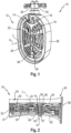
- Such an exhaust gas heater 10 can be flowed through in the exhaust system 12 by exhaust gas in a main exhaust gas flow direction H and has two heating conductors 14, 16 of a heating conductor arrangement generally designated 18, which are arranged one after the other in the direction of an exhaust gas heater longitudinal axis L and can thus be successively flowed around by exhaust gas flowing essentially in the main exhaust gas flow direction H.
- the heating conductors 14, 16 are essentially plate-like or made of flat material and can be produced with their structure provided with a plurality of sections running in a meandering structure by cutting out a flat material blank, in particular a metal blank.
- essentially plate-like carrier elements 20, 22 of a carrier arrangement generally designated 24 On the sides of the two heating conductors 14, 16 facing away from each other in the direction of the exhaust gas heater's longitudinal axis L, there are provided essentially plate-like carrier elements 20, 22 of a carrier arrangement generally designated 24.
- the plate-like carrier elements 20, 22 are fixed to an essentially cylindrical carrier housing 26 on their outer peripheral region.
- the two heating conductors 14, 16 can be connected in series or in parallel.
- two connection units 28, 30 are provided which pass through the carrier housing 26 and are electrically connected to the heating conductors 14, 16 in the interior space surrounded by the carrier housing 26.
- connection arrangement 31 with a plurality of bolt-like connecting elements 32.
- the connecting elements 32 can be designed, for example, as screw bolts with a shaft 34 and a head 36.
- a nut element 37 can be screwed onto the shaft 34, for example, in order to clamp the layered structure of support elements 20, 22 and heating conductors 14, 16 between the head 36 and the nut element 37.
- a carrier arrangement support unit 38 is provided between the heating conductor element 14 and the carrier element 20, for example in association with each connecting element 32.
- the support assembly support unit is constructed from electrically insulating material, for example ceramic material, and is essentially plate-shaped and penetrated by the associated connecting element 32 in the region of an opening provided therein.
- a carrier element support unit 40 is provided between the heating conductor 16 and the carrier element 22, for example in association with each connecting element 32.
- a heating conductor support unit 42 is provided, for example, in association with each connecting element 32.
- Each heating conductor support unit 42 is also essentially designed as a plate with one or more disks and is constructed of ceramic material. Where the heating conductors 14, 16 are penetrated by the connecting element 32, sleeve-like insulating elements 47 are inserted into the openings formed in the heating conductors 14, 16 in order to achieve a defined positioning of the connecting element 32 in the openings provided in the heating conductors 14, 16.
- the Fig.3 shows a detailed section of the exhaust gas heater 10 in the area of a connecting element 32 of the connecting arrangement 31.
- the Fig.3 in their areas to the left and right of the illustrated connecting element 32, two different designs of the heating conductor arrangement 18 are shown.
- a heating conductor arrangement 18 with two heating conductors 14, 16 arranged one after the other in the direction of the exhaust gas heater longitudinal axis L and arranged at a distance from one another is shown.
- Fig.3 a heating conductor arrangement 18 with only a single heating conductor 14' is shown.
- the manner in which the heating conductor arrangement 18 is supported in the manner described below by means of the connection arrangement 32 on the carrier arrangement 24 or the two carrier elements 20, 22 thereof is, however, independent of the number of heating conductors in the heating conductor arrangement 18.
- each of the heating conductors 14, 16 or 14' of the heating conductor arrangement 18 on the carrier arrangement 24 is not implemented by a support arrangement acting between the heating conductors 14, 16 or 14' and the carrier elements 20, 22, but that the heating conductors 14, 16 or the single heating conductor 14' is supported on the carrier arrangement 24 in an electrically insulated manner by means of an insulating carrier unit 44 provided in association with the connecting element 32.
- an insulating carrier unit 44 producing a firm connection with the heating conductor arrangement 18 is preferably provided in association with a plurality, most preferably in association with each connecting element 32 of the connecting arrangement 31.
- the insulating support unit 44 comprises a support sleeve 46 surrounding the shaft 34 of the connecting element 32 designed as a stepped bolt.
- a gap formed between the ring-shaped support sleeve 36, which preferably surrounds the shaft 34 in its entire circumferential area, and the shaft 34 is filled with insulating material 48.
- the insulating material 48 creates a solid connection between the shaft 34 of the connecting element 32 and the support sleeve 46 in both the radial direction and the axial direction.
- the heating conductor arrangement 18 or its heating conductors 14, 16 or 14' are connected to the carrier sleeve 46 by material connection, for example by Fig.3 recognizable welds 50, 52 or 50'.
- the heating conductors 14, 16 or 14' can have an opening where such a fixed connection with the carrier sleeve 46 is to be created, through which the carrier sleeve 46 is passed and then connected to the respective heating conductor 14, 16 or 14' by, for example, a completely circumferential weld seam or by spot welding.
- the carrier sleeve 46 is dimensioned or fixed to the shaft 34 of the connecting element 32 in such a way that it has an axial distance from the two carrier elements 20, 22, which are also constructed of metal material, for example, there is no possibility of an electrical short circuit between the carrier elements 20, 22 and the carrier sleeve 46.
- the heating conductor arrangement 18 is thus held in a defined position axially between the two carrier elements 20, 22 of the carrier arrangement 24 via the insulating carrier unit 44 and the connecting element 32 or each connecting element 32 that interacts with such an insulating carrier unit 44. Additional measures for axially supporting the heating conductors 14, 16 or 14' are not required.
- the solid connection of the carrier sleeve 46 with the shaft 34 of the connecting element 32 can be created, for example, by pouring the insulating material 48 in a flowable, for example melted, state into the space formed between the carrier sleeve 46 and the shaft 34.
- glass ceramic material can be used for this purpose, which after the Curing provides an adhesive, material-locking connection to both the shaft 34 and the carrier sleeve 46.
- the insulating material 48 can be introduced by pressing it into the gap formed between the carrier sleeve 46 and the shaft 34.
- powdery material such as magnesium oxide material
- a force connection i.e. a frictional connection
- an adhesive that strengthens the structural cohesion of the initially powdery insulating material 48 can be integrated.
- the insulating material can comprise fiber material, such as fiber mat material, which is also used, for example, to hold catalyst blocks in essentially tubular catalyst housings of exhaust systems.
- the shaft 34 can be surrounded with fiber material and then the carrier sleeve 46 can be pushed onto the shaft 34 surrounded by the fiber material or the fiber mat material, the fiber material being pressed and creating the firm bond between the shaft 34 and the carrier sleeve 46 by frictional engagement.
- a procedure can be followed in which a connecting element-carrier sleeve assembly 54 is first provided with the or each connecting element 32 of the connecting arrangement 31 and a respective associated carrier sleeve 46 by fixing the carrier sleeve 46 to the associated connecting element 32 by introducing the insulating material 48 in one of the ways described above.
- the connecting element-carrier sleeve assemblies 54 thus provided can then be firmly connected to the heating conductors 14, 16 or 14' of the heating conductor arrangement 18 in a next process step in order to provide a connecting arrangement-heating conductor arrangement assembly 56 in this way.
- the carrier sleeves 46 of the connecting element-carrier sleeve assemblies 54 to be provided in an exhaust gas heater 10 can be firmly connected in the manner described above to the heating conductor(s) of the heating conductor arrangement 18 by producing the welds 50, 52 or 50', if necessary in an alternative procedure by soldering.
- connection arrangement-heating conductor arrangement assembly 56 produced in this way can then be connected to the two carrier elements 20, 22 of the carrier arrangement 24 by threaded sections provided in the axial end regions 58, 60 of the connecting elements 32 designed as stepped bolts being guided through associated openings in the carrier elements 20, 22 and nut elements 37, 37' then being screwed onto these threaded sections.
- the axial end regions 58, 60 of the connecting elements 32 could also be fixed to the carrier elements 20, for example by material bonding, e.g. welding.
- the heating conductor arrangement 18 can first be firmly connected to the carrier sleeve(s) 46, for example by means of a material bond.
- the associated connecting elements 32 can then be inserted into the carrier sleeves 46 already connected to the heating conductors 14, 16 or 14' of the heating conductor arrangement 18 and fixed therein by the insulating material 48.
- the measure for providing a respective connecting element-carrier sleeve assembly 54 is therefore carried out after the measure for connecting the heating conductor arrangement 18 to the carrier sleeve(s) 46.
- the measure for providing the connecting arrangement-heating conductor arrangement assembly 56 is therefore carried out before or nested within the measure for providing the connecting element-carrier sleeve assembly 54.
- an exhaust gas heater provided or to be provided according to the invention, a reliable electrically insulated mounting of a heating conductor arrangement on a support arrangement of an exhaust gas heater is realized with a structurally simple design, which due to the connections used different components with each other mechanically and thermally and is also resistant to chemical influences.
Landscapes
- Engineering & Computer Science (AREA)
- Chemical & Material Sciences (AREA)
- Chemical Kinetics & Catalysis (AREA)
- Combustion & Propulsion (AREA)
- Mechanical Engineering (AREA)
- General Engineering & Computer Science (AREA)
- Health & Medical Sciences (AREA)
- Toxicology (AREA)
- Exhaust Gas After Treatment (AREA)
- Resistance Heating (AREA)
Claims (15)
- Un réchauffeur de gaz d'échappement pour un système de gaz d'échappement d'un moteur à combustion interne, comprenant :- un agencement de support (24),- un agencement de conducteur de chauffage (18) supporté par l'agencement de support (24) et comportant au moins un conducteur de chauffage porteur de courant (14, 16 ; 14'),- un agencement de raccordement (31) pour le raccordement fixe de l'agencement de conducteur de chauffage (18) à l'agencement de support (24), dans lequel l'agencement de conducteur de chauffage (18) est supporté sur l'agencement de support (24) de manière électriquement isolée au moyen de l'agencement de raccordement (31),dans lequel l'agencement de raccordement (31) comprend une pluralité d'éléments de raccordement (32), dans lequel le dispositif de conducteur de chauffage (18) est supporté sur au moins un élément de raccordement (32) au moyen d'une unité de support isolante (44) d'une manière électriquement isolée par rapport à au moins un élément de raccordement (32), dans lequel ledit au moins un élément de raccordement (32) comprend une tige (34),caractérisé en ce que l'unité de support isolante (44) comprend un manchon de support (46), qui entoure la tige (34), et comprend un matériau isolant (48) qui soutient le manchon de support sur la tige (34), et en ce que l'agencement de conducteur de chauffage (18) comprend au moins un conducteur de chauffage (14, 16 ; 14') qui est relié de manière fixe à au moins un manchon de support (46).
- Le réchauffeur de gaz d'échappement selon la revendication 1, caractérisé en ce que ledit au moins un conducteur de chauffage (14, 16 ; 14') est relié de manière fixe à chaque manchon de support (46) au moyen d'un raccordement intégrale, de préférence par soudage ou brasage.
- Le réchauffeur de gaz d'échappement selon la revendication 1 ou 2, caractérisé en ce que l'agencement de conducteur de chauffage (18) comprend une pluralité de conducteurs de chauffage (14, 16) qui sont disposés à une certaine distance les uns des autres de manière à se suivre dans la direction de l'axe longitudinal du réchauffeur de gaz d'échappement (L), et dans lequel chaque conducteur de chauffage (14, 16) est relié de manière fixe à au moins un, de préférence à chaque, manchon de support.
- Le réchauffeur de gaz d'échappement selon l'une des revendications 1 à 3, caractérisé en ce que le matériau isolant (48) assure une liaison intégrale avec la tige (34) et le manchon de support (46).
- Le réchauffeur de gaz d'échappement selon l'une des revendications 1 à 4, caractérisé en ce que le matériau isolant (48) est introduit à l'état fluide dans un espace intermédiaire formé entre la tige (34) et le manchon de support (46), et/ou en ce que le matériau isolant (48) comprend un matériau vitrocéramique.
- Le réchauffeur de gaz d'échappement selon l'une des revendications 1 à 3, caractérisé en ce que le matériau isolant (48) fournit un raccordement non positif à la tige (34) et au manchon de support.
- Le réchauffeur de gaz d'échappement selon l'une des revendications 1 à 3 ou 6, caractérisé en ce que le matériau isolant (48) est introduit, par pressage, dans un espace intermédiaire formé entre la tige (34) et le manchon de support (46), et/ou en ce que le matériau isolant (48) comprend un matériau en poudre pressé, de préférence un matériau en oxyde de magnésium, ou un matériau en fibre pressé, de préférence un matériau de matage en fibre de verre.
- Le réchauffeur de gaz d'échappement selon l'une des revendications 1 à 7, caractérisé en ce que l'agencement de support (24) comprend deux éléments de support (20, 22) qui sont disposés à une certaine distance l'un de l'autre dans la direction de l'axe longitudinal du réchauffeur de gaz d'échappement (L) et qui reçoivent l'agencement de conducteur de chauffage (18) entre eux, et en ce que l'agencement de conducteur de chauffage (18) est supporté sur l'agencement de support (24) au moyen de l'agencement de raccordement (31) à une distance axiale de chacun des éléments de support (20, 22).
- Le réchauffeur de gaz d'échappement selon la revendication 8, caractérisé en ce que le manchon de support (46) est disposé à une distance axiale de chacun des éléments de support (20, 22).
- Un système de gaz d'échappement pour un moteur à combustion interne, comprenant au moins un réchauffeur de gaz d'échappement (10) selon l'une des revendications 1 à 9.
- Un procédé de fabrication d'un réchauffeur de gaz d'échappement selon l'une des revendications précédentes, comprenant les mesures suivantes :a) fournir au moins un ensemble élément de raccordement/manchon de support (54) avec un manchon de support (46) qui entoure une tige (34) d'un élément de raccordement (32), avec un matériau isolant (48) monté entre les deux, et qui est soutenu sur la tige (34) par l'intermédiaire du matériau isolant (48),b) raccordement fixe de l'agencement de conducteurs de chauffage (18) au manchon de support (46) dudit au moins un ensemble élément de raccordement/manchon de support (54) afin de fournir un ensemble agencement de raccordement/agencement de conducteur de chauffage (56),c) raccordement de l'ensemble agencement de raccordement/agencement de conducteur de chauffage (56) à l'agencement de support (24).
- Le procédé selon la revendication 11, caractérisé en ce que la mesure b) est effectuée avant la mesure a), ou en ce que la mesure b) est effectuée après la mesure a).
- Le procédé selon la revendication 11 ou 12, caractérisé en ce que, dans le cas de la mesure a), le matériau isolant (48) est introduit à l'état fluide dans un espace intermédiaire formé entre la tige (34) et le manchon de support (46), ou en ce que, dans le cas de la mesure a), le matériau isolant (48) est pressé dans l'espace intermédiaire formé entre la tige (34) et le manchon de support (46).
- Le procédé selon l'une des revendications 11 à 13, caractérisé en ce que, dans le cas de la mesure b), au moins un conducteur de chauffage (14, 16 ; 14'), de préférence une pluralité de conducteurs de chauffage (14, 16), est/sont relié(s) de manière fixe au manchon de support (46) au moyen d'un raccordement intégral.
- Le procédé selon l'une des revendications 11 à 14, caractérisé en ce que, dans le cas de la mesure c), la tige (34) dudit au moins un ensemble élément de raccordement/manchon de support (54) est reliée à un élément de support (20, 22) de l'agencement de support (24), de préférence par un vissage et/ou un raccordement intégral, dans au moins une, de préférence chaque, zone d'extrémité (58, 60) qui se trouve dans la direction de l'axe longitudinal du réchauffeur de gaz d'échappement (L).
Applications Claiming Priority (1)
| Application Number | Priority Date | Filing Date | Title |
|---|---|---|---|
| DE102021122082.3A DE102021122082A1 (de) | 2021-08-26 | 2021-08-26 | Abgasheizer und Verfahren zur Herstellung eines Abgasheizers |
Publications (2)
| Publication Number | Publication Date |
|---|---|
| EP4141229A1 EP4141229A1 (fr) | 2023-03-01 |
| EP4141229B1 true EP4141229B1 (fr) | 2024-04-10 |
Family
ID=82781005
Family Applications (1)
| Application Number | Title | Priority Date | Filing Date |
|---|---|---|---|
| EP22187407.6A Active EP4141229B1 (fr) | 2021-08-26 | 2022-07-28 | Chauffage à gaz d'échappement et procédé de fabrication d'un chauffage à gaz d'échappement |
Country Status (6)
| Country | Link |
|---|---|
| US (1) | US11838995B2 (fr) |
| EP (1) | EP4141229B1 (fr) |
| JP (1) | JP7502379B2 (fr) |
| KR (1) | KR102776980B1 (fr) |
| CN (1) | CN115717563A (fr) |
| DE (1) | DE102021122082A1 (fr) |
Families Citing this family (2)
| Publication number | Priority date | Publication date | Assignee | Title |
|---|---|---|---|---|
| DE102022102376A1 (de) | 2022-02-02 | 2023-08-03 | Purem GmbH | Abgasheizer |
| DE102022131967A1 (de) * | 2022-12-02 | 2024-06-13 | Purem GmbH | Abstützeinheit zur Abstützung eines Heizleiters eines Abgasheizers an einer Trägerstruktur |
Family Cites Families (15)
| Publication number | Priority date | Publication date | Assignee | Title |
|---|---|---|---|---|
| US5140813A (en) * | 1990-10-31 | 1992-08-25 | Whittenberger William A | Composite catalytic converter |
| JP3035035B2 (ja) * | 1991-11-21 | 2000-04-17 | 日本碍子株式会社 | ヒーターユニット |
| DE19533088A1 (de) * | 1995-09-07 | 1997-03-13 | Emitec Emissionstechnologie | Elektrische isolierende Durchführung mit einer Elektrokorrosionsschutzeinrichtung |
| DE19723121C1 (de) * | 1997-06-03 | 1999-02-04 | Heraeus Electro Nite Int | Elektrische Kontaktierung eines Heizleiters |
| JP2001082129A (ja) | 1999-09-17 | 2001-03-27 | Hitachi Hometec Ltd | 発熱体ユニット |
| JP2002260831A (ja) | 2001-02-27 | 2002-09-13 | Asano Laboratories Co Ltd | ヒータユニットおよびヒータ部材 |
| JP2002295236A (ja) * | 2001-03-30 | 2002-10-09 | Hitachi Hometec Ltd | 発熱体ユニット |
| JP2003075019A (ja) * | 2001-08-31 | 2003-03-12 | Mitsubishi Heavy Ind Ltd | ガスヒートポンプ式空気調和装置及び排気ガス加熱用燃焼装置 |
| EP2935996B1 (fr) * | 2012-12-18 | 2019-03-20 | Watlow Electric Manufacturing Company | Appareil de chauffage de gaz d'échappement perfectionné et procédé de chauffage |
| FR3085429B1 (fr) * | 2018-09-03 | 2020-11-27 | Faurecia Systemes Dechappement | Dispositif perfectionne de chauffage de gaz d'echappement, notamment pour un vehicule automobile |
| DE102018217438A1 (de) * | 2018-10-11 | 2020-04-16 | Continental Automotive Gmbh | Vorrichtung zur Abgasbehandlung |
| DE102019107384A1 (de) * | 2019-03-22 | 2020-09-24 | Eberspächer Exhaust Technology GmbH & Co. KG | Abgasheizelement |
| DE202021102620U1 (de) * | 2020-11-30 | 2021-07-23 | Faurecia Emissions Control Technologies, Germany Gmbh | Heizvorrichtung für ein Abgassystem und Abgassystem |
| EP4047195A1 (fr) * | 2021-02-11 | 2022-08-24 | Benteler Automobiltechnik GmbH | Support pour un élément chauffant électrique dans un dispositif de post-traitement des gaz d'échappement |
| DE102021109568A1 (de) | 2021-03-15 | 2022-09-15 | Purem GmbH | Abgasheizer |
-
2021
- 2021-08-26 DE DE102021122082.3A patent/DE102021122082A1/de active Pending
-
2022
- 2022-07-28 EP EP22187407.6A patent/EP4141229B1/fr active Active
- 2022-08-25 JP JP2022133900A patent/JP7502379B2/ja active Active
- 2022-08-25 CN CN202211023461.1A patent/CN115717563A/zh active Pending
- 2022-08-26 KR KR1020220107941A patent/KR102776980B1/ko active Active
- 2022-08-26 US US17/822,486 patent/US11838995B2/en active Active
Also Published As
| Publication number | Publication date |
|---|---|
| DE102021122082A1 (de) | 2023-03-02 |
| EP4141229A1 (fr) | 2023-03-01 |
| JP7502379B2 (ja) | 2024-06-18 |
| KR102776980B1 (ko) | 2025-03-07 |
| CN115717563A (zh) | 2023-02-28 |
| KR20230031177A (ko) | 2023-03-07 |
| JP2023033216A (ja) | 2023-03-09 |
| US11838995B2 (en) | 2023-12-05 |
| US20230061713A1 (en) | 2023-03-02 |
Similar Documents
| Publication | Publication Date | Title |
|---|---|---|
| EP3964696B1 (fr) | Chauffage de gaz d'échappement | |
| EP2836687B1 (fr) | Connection électrique de plusieurs couches en tôle d'un corps en nid d'abeille et corps en nid d'abeille correspondant | |
| EP2744990B1 (fr) | Dispositif de traitement de gaz d'échappement | |
| DE202021102620U1 (de) | Heizvorrichtung für ein Abgassystem und Abgassystem | |
| EP3904647B1 (fr) | Unité de raccordement pour un chauffage à gaz d'échappement | |
| EP3207229B1 (fr) | Structure porteur, dispositif pour le traitement de gaz d'échappement et son procédé de fabrication | |
| EP3320196B1 (fr) | Corps en nid d'abeilles pouvant être chauffé électriquement avec interconnexion électrique de modules multicouches | |
| EP0581784A1 (fr) | Corps en nid d'abeille pouvant etre chauffe electriquement | |
| DE102019121382A1 (de) | Abgasbehandlungseinrichtung und Fahrzeug | |
| EP4141229A1 (fr) | Chauffage à gaz d'échappement et procédé de fabrication d'un chauffage à gaz d'échappement | |
| EP3943720B1 (fr) | Dispositif de chauffage électrique | |
| EP4141230B1 (fr) | Chauffage pour gaz d'échappement | |
| EP4174294A1 (fr) | Unité de chauffage pour un système d'échappement d'un moteur à combustion interne | |
| DE112004001022T5 (de) | Herstellungsverfahren für ein elektrisches Heizmodul unter Verwendung einer Schablone und das elektrische Heizmodul | |
| WO2022033630A1 (fr) | Machine électrique comprenant un mécanisme de protection sur un joint soudé, et procédé d'assemblage de la machine électrique | |
| EP4174295B1 (fr) | Broche de raccordement | |
| EP4144965B1 (fr) | Élément de chauffage de gaz d'échappement | |
| EP4198273B1 (fr) | Dispositif de chauffage de gaz d'échappement | |
| DE102022111864B4 (de) | Heizvorrichtung | |
| EP4141228B1 (fr) | Chauffage de gaz d'échappement | |
| DE3821435A1 (de) | Heizeinheit | |
| EP4286662B1 (fr) | Unité de raccordement | |
| EP4141227B1 (fr) | Élément chauffant de gaz d'échappement | |
| DE102021132931B4 (de) | Abgasheizanordnung für eine Abgasanlage einer Brennkraftmaschine | |
| DE102019110359A1 (de) | Abgasbehandlungseinrichtung und Fahrzeug |
Legal Events
| Date | Code | Title | Description |
|---|---|---|---|
| PUAI | Public reference made under article 153(3) epc to a published international application that has entered the european phase |
Free format text: ORIGINAL CODE: 0009012 |
|
| STAA | Information on the status of an ep patent application or granted ep patent |
Free format text: STATUS: THE APPLICATION HAS BEEN PUBLISHED |
|
| AK | Designated contracting states |
Kind code of ref document: A1 Designated state(s): AL AT BE BG CH CY CZ DE DK EE ES FI FR GB GR HR HU IE IS IT LI LT LU LV MC MK MT NL NO PL PT RO RS SE SI SK SM TR |
|
| STAA | Information on the status of an ep patent application or granted ep patent |
Free format text: STATUS: REQUEST FOR EXAMINATION WAS MADE |
|
| 17P | Request for examination filed |
Effective date: 20230616 |
|
| RBV | Designated contracting states (corrected) |
Designated state(s): AL AT BE BG CH CY CZ DE DK EE ES FI FR GB GR HR HU IE IS IT LI LT LU LV MC MK MT NL NO PL PT RO RS SE SI SK SM TR |
|
| GRAP | Despatch of communication of intention to grant a patent |
Free format text: ORIGINAL CODE: EPIDOSNIGR1 |
|
| STAA | Information on the status of an ep patent application or granted ep patent |
Free format text: STATUS: GRANT OF PATENT IS INTENDED |
|
| RIC1 | Information provided on ipc code assigned before grant |
Ipc: F01N 3/20 20060101AFI20231229BHEP |
|
| INTG | Intention to grant announced |
Effective date: 20240130 |
|
| GRAS | Grant fee paid |
Free format text: ORIGINAL CODE: EPIDOSNIGR3 |
|
| GRAA | (expected) grant |
Free format text: ORIGINAL CODE: 0009210 |
|
| STAA | Information on the status of an ep patent application or granted ep patent |
Free format text: STATUS: THE PATENT HAS BEEN GRANTED |
|
| AK | Designated contracting states |
Kind code of ref document: B1 Designated state(s): AL AT BE BG CH CY CZ DE DK EE ES FI FR GB GR HR HU IE IS IT LI LT LU LV MC MK MT NL NO PL PT RO RS SE SI SK SM TR |
|
| REG | Reference to a national code |
Ref country code: GB Ref legal event code: FG4D Free format text: NOT ENGLISH |
|
| REG | Reference to a national code |
Ref country code: CH Ref legal event code: EP |
|
| REG | Reference to a national code |
Ref country code: DE Ref legal event code: R096 Ref document number: 502022000729 Country of ref document: DE |
|
| REG | Reference to a national code |
Ref country code: IE Ref legal event code: FG4D Free format text: LANGUAGE OF EP DOCUMENT: GERMAN |
|
| REG | Reference to a national code |
Ref country code: LT Ref legal event code: MG9D |
|
| REG | Reference to a national code |
Ref country code: NL Ref legal event code: MP Effective date: 20240410 |
|
| PG25 | Lapsed in a contracting state [announced via postgrant information from national office to epo] |
Ref country code: NL Free format text: LAPSE BECAUSE OF FAILURE TO SUBMIT A TRANSLATION OF THE DESCRIPTION OR TO PAY THE FEE WITHIN THE PRESCRIBED TIME-LIMIT Effective date: 20240410 |
|
| PG25 | Lapsed in a contracting state [announced via postgrant information from national office to epo] |
Ref country code: NL Free format text: LAPSE BECAUSE OF FAILURE TO SUBMIT A TRANSLATION OF THE DESCRIPTION OR TO PAY THE FEE WITHIN THE PRESCRIBED TIME-LIMIT Effective date: 20240410 |
|
| PG25 | Lapsed in a contracting state [announced via postgrant information from national office to epo] |
Ref country code: IS Free format text: LAPSE BECAUSE OF FAILURE TO SUBMIT A TRANSLATION OF THE DESCRIPTION OR TO PAY THE FEE WITHIN THE PRESCRIBED TIME-LIMIT Effective date: 20240810 |
|
| PG25 | Lapsed in a contracting state [announced via postgrant information from national office to epo] |
Ref country code: BG Free format text: LAPSE BECAUSE OF FAILURE TO SUBMIT A TRANSLATION OF THE DESCRIPTION OR TO PAY THE FEE WITHIN THE PRESCRIBED TIME-LIMIT Effective date: 20240410 |
|
| PG25 | Lapsed in a contracting state [announced via postgrant information from national office to epo] |
Ref country code: FI Free format text: LAPSE BECAUSE OF FAILURE TO SUBMIT A TRANSLATION OF THE DESCRIPTION OR TO PAY THE FEE WITHIN THE PRESCRIBED TIME-LIMIT Effective date: 20240410 Ref country code: HR Free format text: LAPSE BECAUSE OF FAILURE TO SUBMIT A TRANSLATION OF THE DESCRIPTION OR TO PAY THE FEE WITHIN THE PRESCRIBED TIME-LIMIT Effective date: 20240410 |
|
| PG25 | Lapsed in a contracting state [announced via postgrant information from national office to epo] |
Ref country code: GR Free format text: LAPSE BECAUSE OF FAILURE TO SUBMIT A TRANSLATION OF THE DESCRIPTION OR TO PAY THE FEE WITHIN THE PRESCRIBED TIME-LIMIT Effective date: 20240711 |
|
| PG25 | Lapsed in a contracting state [announced via postgrant information from national office to epo] |
Ref country code: PT Free format text: LAPSE BECAUSE OF FAILURE TO SUBMIT A TRANSLATION OF THE DESCRIPTION OR TO PAY THE FEE WITHIN THE PRESCRIBED TIME-LIMIT Effective date: 20240812 |
|
| PG25 | Lapsed in a contracting state [announced via postgrant information from national office to epo] |
Ref country code: ES Free format text: LAPSE BECAUSE OF FAILURE TO SUBMIT A TRANSLATION OF THE DESCRIPTION OR TO PAY THE FEE WITHIN THE PRESCRIBED TIME-LIMIT Effective date: 20240410 |
|
| PG25 | Lapsed in a contracting state [announced via postgrant information from national office to epo] |
Ref country code: PL Free format text: LAPSE BECAUSE OF FAILURE TO SUBMIT A TRANSLATION OF THE DESCRIPTION OR TO PAY THE FEE WITHIN THE PRESCRIBED TIME-LIMIT Effective date: 20240410 |
|
| PG25 | Lapsed in a contracting state [announced via postgrant information from national office to epo] |
Ref country code: LV Free format text: LAPSE BECAUSE OF FAILURE TO SUBMIT A TRANSLATION OF THE DESCRIPTION OR TO PAY THE FEE WITHIN THE PRESCRIBED TIME-LIMIT Effective date: 20240410 |
|
| PG25 | Lapsed in a contracting state [announced via postgrant information from national office to epo] |
Ref country code: PT Free format text: LAPSE BECAUSE OF FAILURE TO SUBMIT A TRANSLATION OF THE DESCRIPTION OR TO PAY THE FEE WITHIN THE PRESCRIBED TIME-LIMIT Effective date: 20240812 Ref country code: PL Free format text: LAPSE BECAUSE OF FAILURE TO SUBMIT A TRANSLATION OF THE DESCRIPTION OR TO PAY THE FEE WITHIN THE PRESCRIBED TIME-LIMIT Effective date: 20240410 Ref country code: NO Free format text: LAPSE BECAUSE OF FAILURE TO SUBMIT A TRANSLATION OF THE DESCRIPTION OR TO PAY THE FEE WITHIN THE PRESCRIBED TIME-LIMIT Effective date: 20240710 Ref country code: LV Free format text: LAPSE BECAUSE OF FAILURE TO SUBMIT A TRANSLATION OF THE DESCRIPTION OR TO PAY THE FEE WITHIN THE PRESCRIBED TIME-LIMIT Effective date: 20240410 Ref country code: IS Free format text: LAPSE BECAUSE OF FAILURE TO SUBMIT A TRANSLATION OF THE DESCRIPTION OR TO PAY THE FEE WITHIN THE PRESCRIBED TIME-LIMIT Effective date: 20240810 Ref country code: HR Free format text: LAPSE BECAUSE OF FAILURE TO SUBMIT A TRANSLATION OF THE DESCRIPTION OR TO PAY THE FEE WITHIN THE PRESCRIBED TIME-LIMIT Effective date: 20240410 Ref country code: GR Free format text: LAPSE BECAUSE OF FAILURE TO SUBMIT A TRANSLATION OF THE DESCRIPTION OR TO PAY THE FEE WITHIN THE PRESCRIBED TIME-LIMIT Effective date: 20240711 Ref country code: FI Free format text: LAPSE BECAUSE OF FAILURE TO SUBMIT A TRANSLATION OF THE DESCRIPTION OR TO PAY THE FEE WITHIN THE PRESCRIBED TIME-LIMIT Effective date: 20240410 Ref country code: ES Free format text: LAPSE BECAUSE OF FAILURE TO SUBMIT A TRANSLATION OF THE DESCRIPTION OR TO PAY THE FEE WITHIN THE PRESCRIBED TIME-LIMIT Effective date: 20240410 Ref country code: BG Free format text: LAPSE BECAUSE OF FAILURE TO SUBMIT A TRANSLATION OF THE DESCRIPTION OR TO PAY THE FEE WITHIN THE PRESCRIBED TIME-LIMIT Effective date: 20240410 Ref country code: RS Free format text: LAPSE BECAUSE OF FAILURE TO SUBMIT A TRANSLATION OF THE DESCRIPTION OR TO PAY THE FEE WITHIN THE PRESCRIBED TIME-LIMIT Effective date: 20240710 |
|
| REG | Reference to a national code |
Ref country code: DE Ref legal event code: R097 Ref document number: 502022000729 Country of ref document: DE |
|
| PG25 | Lapsed in a contracting state [announced via postgrant information from national office to epo] |
Ref country code: DK Free format text: LAPSE BECAUSE OF FAILURE TO SUBMIT A TRANSLATION OF THE DESCRIPTION OR TO PAY THE FEE WITHIN THE PRESCRIBED TIME-LIMIT Effective date: 20240410 |
|
| PG25 | Lapsed in a contracting state [announced via postgrant information from national office to epo] |
Ref country code: EE Free format text: LAPSE BECAUSE OF FAILURE TO SUBMIT A TRANSLATION OF THE DESCRIPTION OR TO PAY THE FEE WITHIN THE PRESCRIBED TIME-LIMIT Effective date: 20240410 |
|
| PG25 | Lapsed in a contracting state [announced via postgrant information from national office to epo] |
Ref country code: CZ Free format text: LAPSE BECAUSE OF FAILURE TO SUBMIT A TRANSLATION OF THE DESCRIPTION OR TO PAY THE FEE WITHIN THE PRESCRIBED TIME-LIMIT Effective date: 20240410 |
|
| PG25 | Lapsed in a contracting state [announced via postgrant information from national office to epo] |
Ref country code: SK Free format text: LAPSE BECAUSE OF FAILURE TO SUBMIT A TRANSLATION OF THE DESCRIPTION OR TO PAY THE FEE WITHIN THE PRESCRIBED TIME-LIMIT Effective date: 20240410 Ref country code: RO Free format text: LAPSE BECAUSE OF FAILURE TO SUBMIT A TRANSLATION OF THE DESCRIPTION OR TO PAY THE FEE WITHIN THE PRESCRIBED TIME-LIMIT Effective date: 20240410 |
|
| PG25 | Lapsed in a contracting state [announced via postgrant information from national office to epo] |
Ref country code: SM Free format text: LAPSE BECAUSE OF FAILURE TO SUBMIT A TRANSLATION OF THE DESCRIPTION OR TO PAY THE FEE WITHIN THE PRESCRIBED TIME-LIMIT Effective date: 20240410 |
|
| PG25 | Lapsed in a contracting state [announced via postgrant information from national office to epo] |
Ref country code: SM Free format text: LAPSE BECAUSE OF FAILURE TO SUBMIT A TRANSLATION OF THE DESCRIPTION OR TO PAY THE FEE WITHIN THE PRESCRIBED TIME-LIMIT Effective date: 20240410 Ref country code: SK Free format text: LAPSE BECAUSE OF FAILURE TO SUBMIT A TRANSLATION OF THE DESCRIPTION OR TO PAY THE FEE WITHIN THE PRESCRIBED TIME-LIMIT Effective date: 20240410 Ref country code: RO Free format text: LAPSE BECAUSE OF FAILURE TO SUBMIT A TRANSLATION OF THE DESCRIPTION OR TO PAY THE FEE WITHIN THE PRESCRIBED TIME-LIMIT Effective date: 20240410 Ref country code: EE Free format text: LAPSE BECAUSE OF FAILURE TO SUBMIT A TRANSLATION OF THE DESCRIPTION OR TO PAY THE FEE WITHIN THE PRESCRIBED TIME-LIMIT Effective date: 20240410 Ref country code: DK Free format text: LAPSE BECAUSE OF FAILURE TO SUBMIT A TRANSLATION OF THE DESCRIPTION OR TO PAY THE FEE WITHIN THE PRESCRIBED TIME-LIMIT Effective date: 20240410 Ref country code: CZ Free format text: LAPSE BECAUSE OF FAILURE TO SUBMIT A TRANSLATION OF THE DESCRIPTION OR TO PAY THE FEE WITHIN THE PRESCRIBED TIME-LIMIT Effective date: 20240410 |
|
| PG25 | Lapsed in a contracting state [announced via postgrant information from national office to epo] |
Ref country code: MC Free format text: LAPSE BECAUSE OF FAILURE TO SUBMIT A TRANSLATION OF THE DESCRIPTION OR TO PAY THE FEE WITHIN THE PRESCRIBED TIME-LIMIT Effective date: 20240410 Ref country code: IT Free format text: LAPSE BECAUSE OF FAILURE TO SUBMIT A TRANSLATION OF THE DESCRIPTION OR TO PAY THE FEE WITHIN THE PRESCRIBED TIME-LIMIT Effective date: 20240410 |
|
| PLBE | No opposition filed within time limit |
Free format text: ORIGINAL CODE: 0009261 |
|
| STAA | Information on the status of an ep patent application or granted ep patent |
Free format text: STATUS: NO OPPOSITION FILED WITHIN TIME LIMIT |
|
| PG25 | Lapsed in a contracting state [announced via postgrant information from national office to epo] |
Ref country code: LU Free format text: LAPSE BECAUSE OF NON-PAYMENT OF DUE FEES Effective date: 20240728 |
|
| 26N | No opposition filed |
Effective date: 20250113 |
|
| PG25 | Lapsed in a contracting state [announced via postgrant information from national office to epo] |
Ref country code: LU Free format text: LAPSE BECAUSE OF NON-PAYMENT OF DUE FEES Effective date: 20240728 |
|
| PG25 | Lapsed in a contracting state [announced via postgrant information from national office to epo] |
Ref country code: SI Free format text: LAPSE BECAUSE OF FAILURE TO SUBMIT A TRANSLATION OF THE DESCRIPTION OR TO PAY THE FEE WITHIN THE PRESCRIBED TIME-LIMIT Effective date: 20240410 Ref country code: BE Free format text: LAPSE BECAUSE OF NON-PAYMENT OF DUE FEES Effective date: 20240731 |
|
| REG | Reference to a national code |
Ref country code: BE Ref legal event code: MM Effective date: 20240731 |
|
| PG25 | Lapsed in a contracting state [announced via postgrant information from national office to epo] |
Ref country code: IE Free format text: LAPSE BECAUSE OF NON-PAYMENT OF DUE FEES Effective date: 20240728 |
|
| PG25 | Lapsed in a contracting state [announced via postgrant information from national office to epo] |
Ref country code: SE Free format text: LAPSE BECAUSE OF FAILURE TO SUBMIT A TRANSLATION OF THE DESCRIPTION OR TO PAY THE FEE WITHIN THE PRESCRIBED TIME-LIMIT Effective date: 20240410 |
|
| PGFP | Annual fee paid to national office [announced via postgrant information from national office to epo] |
Ref country code: DE Payment date: 20250722 Year of fee payment: 4 |
|
| PGFP | Annual fee paid to national office [announced via postgrant information from national office to epo] |
Ref country code: FR Payment date: 20250723 Year of fee payment: 4 Ref country code: AT Payment date: 20251020 Year of fee payment: 4 |
|
| PG25 | Lapsed in a contracting state [announced via postgrant information from national office to epo] |
Ref country code: CY Free format text: LAPSE BECAUSE OF FAILURE TO SUBMIT A TRANSLATION OF THE DESCRIPTION OR TO PAY THE FEE WITHIN THE PRESCRIBED TIME-LIMIT; INVALID AB INITIO Effective date: 20220728 |
|
| REG | Reference to a national code |
Ref country code: CH Ref legal event code: H13 Free format text: ST27 STATUS EVENT CODE: U-0-0-H10-H13 (AS PROVIDED BY THE NATIONAL OFFICE) Effective date: 20260224 |
|
| PG25 | Lapsed in a contracting state [announced via postgrant information from national office to epo] |
Ref country code: HU Free format text: LAPSE BECAUSE OF FAILURE TO SUBMIT A TRANSLATION OF THE DESCRIPTION OR TO PAY THE FEE WITHIN THE PRESCRIBED TIME-LIMIT; INVALID AB INITIO Effective date: 20220728 |
|
| PG25 | Lapsed in a contracting state [announced via postgrant information from national office to epo] |
Ref country code: CH Free format text: LAPSE BECAUSE OF NON-PAYMENT OF DUE FEES Effective date: 20250731 |