EP4141299B1 - Rückschlagventil mit membran - Google Patents
Rückschlagventil mit membran Download PDFInfo
- Publication number
- EP4141299B1 EP4141299B1 EP22188622.9A EP22188622A EP4141299B1 EP 4141299 B1 EP4141299 B1 EP 4141299B1 EP 22188622 A EP22188622 A EP 22188622A EP 4141299 B1 EP4141299 B1 EP 4141299B1
- Authority
- EP
- European Patent Office
- Prior art keywords
- gate
- lip
- pipe
- check valve
- movable portion
- Prior art date
- Legal status (The legal status is an assumption and is not a legal conclusion. Google has not performed a legal analysis and makes no representation as to the accuracy of the status listed.)
- Active
Links
Images


Classifications
-
- F—MECHANICAL ENGINEERING; LIGHTING; HEATING; WEAPONS; BLASTING
- F16—ENGINEERING ELEMENTS AND UNITS; GENERAL MEASURES FOR PRODUCING AND MAINTAINING EFFECTIVE FUNCTIONING OF MACHINES OR INSTALLATIONS; THERMAL INSULATION IN GENERAL
- F16K—VALVES; TAPS; COCKS; ACTUATING-FLOATS; DEVICES FOR VENTING OR AERATING
- F16K15/00—Check valves
- F16K15/14—Check valves with flexible valve members
- F16K15/144—Check valves with flexible valve members the closure elements being fixed along all or a part of their periphery
- F16K15/147—Check valves with flexible valve members the closure elements being fixed along all or a part of their periphery the closure elements having specially formed slits or being of an elongated easily collapsible form
-
- E—FIXED CONSTRUCTIONS
- E03—WATER SUPPLY; SEWERAGE
- E03F—SEWERS; CESSPOOLS
- E03F7/00—Other installations or implements for operating sewer systems, e.g. for preventing or indicating stoppage; Emptying cesspools
- E03F7/02—Shut-off devices
- E03F7/04—Valves for preventing return flow
Definitions
- the invention relates to a non-return valve for a pipeline.
- An object of the invention is to overcome these drawbacks, and more particularly to provide a non-return valve which ensures the blocking of a flow of fluid in a first direction and which allows a flow of fluid in a second opposite direction with a lower flow rate than the configurations of the prior art.
- the door has two reinforcement zones defining a curvature opposite the curvature of the movable lip and the hinges, the two reinforcement zones separating the movable portion and the fixed portion.
- both hinges extend beyond the movable lip toward the second end.
- the hinges extend less than half the length of the door, the length being measured in the first direction of movement.
- the lip is extended by a tail towards the second end, the tail having a flat bottom wall or with a radius of curvature greater than 85% of the radius of curvature of the lip.
- the tail has a width which is at least 33% of the internal width of the pipe over at least 50% of the length of the gate.
- the door has planar symmetry.
- the second end of the door is located above a plane passing through the two hinges and perpendicular to the plane of symmetry, the movable portion of the first end being located below said plane.
- the door has planar symmetry.
- the second end of the door is located above a plane passing through the two reinforcement zones and perpendicular to the plane of symmetry, the movable portion of the first end being located below said plane.
- the movable portion extends over a first length between the two hinges.
- the lip represents at least 50% of the first length, the lip having a constant radius of curvature.
- the check valve has a circular section fixing system for fixing to a circular internal wall of the pipeline.
- the circular section and the movable part share the same center.
- the non-return valve comprises a stiffener intended to be fixed to a system for fixing the non-return valve on the pipeline, the fixed portion being fixed to the stiffener and the movable portion being in contact with the stiffener to block the flow of fluid, the stiffener being annular.
- the stiffener forms a step and the lip has a complementary shape covering the step.
- the second end of the door has two through holes and the stiffener has two rods, the two rods passing through the two through holes to stretch the door in the first direction of movement.
- FIG. 1 illustrates a check valve 1 provided with a fastening system 2 configured to be fastened to an internal wall of a pipe 3.
- the check valve 1 is provided with a membrane defining a gate 4 which is configured to allow the passage of a fluid in the pipe 3 in a first direction of movement A.
- the gate 4 is configured to prohibit the passage of the fluid in the pipe 3 in a second direction of movement B which is opposite the first direction of movement A. In this way, the gate 4 only allows a flow of fluid in a single direction inside the pipe 3.
- the check valve 1 In the open position, the check valve 1 allows the flow of liquid from the inlet end to the outlet end, i.e. in the first direction of movement. In the rest position, the check valve 1 blocks the flow of liquid.
- the door 4 has an entry area with a fixed portion 4a and a movable portion 4b.
- the movable portion 4b is mounted movable relative to the fixed portion 4a.
- the movable portion 4b deforms so as to define a first position and a second position.
- the first position called the blocking position and illustrated in Figures 1 to 5
- the movable portion 4b prevents the flow of fluid in the second direction of movement B.
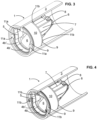
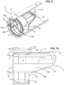
- the movable portion 4b In the second position called the passing position and illustrated in Figures 6 to 10 , the movable portion 4b is deformed which allows a flow of fluid in the first direction of movement A.
- the movable portion 4b and the fixed portion 4a ensure the sealing of the non-return valve 1.
- the inlet zone has an annular section when it blocks the liquid.
- the fixed portion 4a is located above the movable portion once installed in a pipeline 3.
- the first and second directions of movement A and B correspond to the longitudinal direction of pipeline 3.
- the door 4 is in the form of a three-dimensional structure which has a decreasing section from a first end to a second end.
- the second end is opposite the first end in the second direction of movement B.
- the door 4 is in the form of a conical structure and more preferably of a truncated cone shape as illustrated in Figures 1 to 12
- the first end corresponds to the opening of the mouth of the cone, that is to say the entrance of door 4 while the second end corresponds to the bottom of the cone.
- the conical or truncated structure has a decreasing section according to the second direction of movement B.
- the fluid moves in the pipe 3 according to the second direction of movement B, the fluid is introduced inside the gate 4, that is to say inside the cone, which has the effect of generating a force on the internal wall of the membrane. This force presses the wall of the cone towards the internal side wall of the pipe or of the fixing system 2 which makes it more difficult for liquid to pass through the non-return valve 1.
- the fluid when the fluid moves in the first direction of movement A, it encounters the external wall of the door 4.
- the fluid applies a force directed towards the inside of the cone and which has the effect of deforming the entrance of the door 4 and defining a passage for the fluid.
- the fluid exerts a force on the movable portion 4b which deforms to generate a passage.
- the fluid exerts a force which moves the movable portion 4b towards the fixed portion 4a.
- a door 4 having a particular shape so as to ensure effective blocking of the fluid when the latter flows in the second direction of movement B and to have the capacity to deform easily when the fluid flows in the first direction of movement. displacement A.
- the use of a cone corresponding to its mathematical definition, i.e. with a plurality of circular sections that decrease linearly, does not provide a satisfactory result.
- the cone is able to effectively block the flow of fluid in the second direction of movement B, but it is necessary to apply a significant force in the first direction of movement A to obtain sufficient deformation of the cone that allows the passage of a low-flow fluid.
- the cone only deforms if a sufficient height of fluid is present in the pipe 3.
- the first end of the door 4 is formed with a movable portion 4b that has a lip 4b' and two hinges 4b".
- the lip 4b' has a radius of curvature that is greater than the radii of curvature of the two hinges 4b".
- the two hinges 4b" are separated by the lip 4b' and each of the hinges 4b" separates the lip 4b' and the fixed portion 4a. This configuration makes it possible to form a lip 4b' that deforms more easily when a force is applied to the outer wall of the lip 4b' toward the inside of the cone.
- the lip 4b' deforms between a contact position where the lip 4b' closes the door 4 and a deformed position where the lip 4b' defines a channel for the passage of a fluid.
- the documents WO 2020/154801 , WO 2018/006949 And US 2011/013474 disclose configurations where the hinges are formed in the extension of the lip mobile with the same radius of curvature which requires having a significant liquid pressure to deform the lip.
- the entrance area of the door 4 defines two reinforcements 5 which separate the fixed portion 4a and the movable portion 4b.
- the two reinforcements 5 form a narrowing of the width of the entrance of the door 4.
- the width is measured in a longitudinal direction perpendicular to the axis of the pipe 3 when the non-return valve 1 is mounted in the pipe 3.
- each reinforcement 5 defines an inflection of the radius of curvature of the entrance of the door 4.
- each of the reinforcements 5 defines an inversion of curvature relative to the curvature which is present in the movable portion 4b.
- the reinforcement zones 5 separate the fixed portion 4a and the movable portion 4b. Depending on the configurations, the reinforcement zones 5 are mounted fixed or movable relative to the fixing system 2.
- the reinforcement zones 5 are able to concentrate the forces of the liquid on the mobile portion 4b to facilitate the deformation of the mobile portion 4b at low flow rate.
- the radius of curvature of the reinforcement zones 5 has a value which is greater than the value of the radius of curvature of the hinges 4b" in absolute value.
- the pipe 3 has a circular cross-section
- a fixing system 2 which also has a circular external cross-section.
- the centre of the circular external cross-section corresponds to the centre of the radius of curvature of the lip 4b'.
- the movable portion 4b extends from the entrance, i.e. the first end, towards the second end while retaining the lip 4b', the hinges 4b" and the reinforcements 5 over less than 30% of the length of the door 4, preferably less than 20% of the length of the door 4.
- the radius of curvature can be kept constant over the entire length of the movable portion 4b, but it is also possible to provide for a reduction in the radius of curvature as long as the latter remains less than that of the hinges 4b".
- the movable portion 4b In order to facilitate the opening of the door 4 at a low flow rate applied to the external wall of the movable portion 4b, it is advantageous for the movable portion 4b to have a constant radius of curvature over at least 5%, preferably at least 10%, of the length of the door 4. The length is measured on the perimeter of the membrane. Maintaining the radius of curvature makes it possible to reduce the force to be applied to deform the movable portion 4b and form the channel which allows the fluid to pass in the first direction of movement A.
- the movable part 4b is made of polymer material, preferably elastomer.
- the door 4 is entirely made of a polymer material, for example elastomer.
- the movable part 4b deforms elastically between its first position and its second position.
- the thickness of the material forming the fixed portion 4a may be greater than or equal to the thickness of the material forming the movable portion 4b. It is also possible to provide that the thickness of the material forming the two hinges 4b" is greater than or equal to the thickness of the lip 4b'. It is also possible to provide that the thickness of the material forming the fixed portion 4a is greater than or equal to the thickness of the material forming the two reinforcement zones 5.
- the lip 4b In order to facilitate the opening of the door 4 when low flow rates are applied to the external wall of the door, it is advantageous to extend the lip 4b with a tail 6 that extends over at least 30% of the length of the door 4.
- the tail 6 does not intervene in the sealing of the non-return valve 1, that is to say that the tail 6 is not in contact with the pipe 3 or the fixing system 2 or any other element that intervenes in the sealing of the blocking position.
- the tail 6 may be in the form of a flat or slightly rounded portion. By slightly rounded, we mean a radius of curvature that is greater than or equal to the radius of curvature of lip 4b'. The radius of curvature of tail 6 is oriented in the same direction as lip 4b'.
- the length of the tail 6 represents at least 60% of the total length of the door 4, i.e. the sum of the length of the entry zone and the tail 6. If the fixing system 2 only bears on the internal wall of the pipe 3, the width of the tail 6 corresponds to 30% of the width of the fixing system 2. If the fixing system 2 only bears on the external wall of the pipe 3, the width of the tail 6 corresponds to 30% of the support zone on the external wall with removal of the thickness of the pipe 3. Preferably, the width of the tail 6 is at least equal to 50% of the internal width of the pipe 3.
- the door 4 and the tail 6 are part of a single-piece element which forms the membrane.
- the tail 6 is preferably devoid of the reinforcements 5.
- the external wall of the tail 6 is not in contact with another wall to ensure the sealing of the door in the blocking position.
- the cross-section of the gate 4 decreases as one approaches the second end.
- the lower outer wall of the tail 6 moves away from the lower inner wall of the pipe 3, that is, approaches the upper inner wall of the pipe 3 as one approaches the second end.
- the lower wall of the tail is inclined upwards from the inlet to the bottom. This makes it possible to limit the pressure loss when the fluid must circulate in the pipe 3.
- the lower part of the gate 4 is formed by the lip 4b' while the upper part of the gate 4 is formed by the fixed portion 4a.
- the fixed portion 4a of the inlet is extended by a fixed portion of the tail 6 which extends in the longitudinal direction of the pipe 3 so that the upper part of the gate 4 remains at a constant distance from the upper part of the pipe 3 or deviates less than the lower part of the tail 6.
- the lower part of the tail 6 is oriented so as to approach the upper part of the pipe 3 when moving from the first end to the second end.
- the lower wall of the tail 6 has an inclination which makes it possible to reach at least the center of the pipe 3 and preferably at least the upper third of the pipe 3.
- the shape of the pipe 3 corresponds substantially or exactly to the shape of the fixing surface of the fixing system 2.
- the hinge 4b" extends over a length that is greater than the length of the lip 4b' and extends into the tail 6.
- the hinge 4b" extends to the bottom wall of the tail 6.
- the hinge 4b" preferably extends in a longitudinal direction or at an inclination that is less than the inclination of the bottom wall of the tail 6. This embodiment is particularly advantageous when the hinge 4b" extends over a length less than 20% of the longitudinal direction of the pipeline, i.e. along the length of the gate 4 and when the reinforcement zone 5 extends beyond the hinge 4b".
- the edges of the tail 6 are curved so as to close the gate 4 and define a substantially conical or frustoconical element.
- the tail 6 defines a section whose width to height ratio (l/h) decreases as we get closer to the back of gate 4.
- the non-return valve 1 has a stiffener 7 that is configured to stiffen one or more portions of the gate 4. It is advantageous to fix the upper portion of the tail 6 to the pipe 3 and/or to the fixing system by means of the stiffener 7.
- the stiffener 7 prevents the bottom of the gate 4 from deforming in the direction of the lower part of the pipe 3 and partially blocking the pipe 3.
- the use of a stiffener 7 makes it possible to facilitate the formation of the membrane, for example in a single material and advantageously with a thickness which is more homogeneous between the different portions.
- the stiffener 7 provides the interface between the fixing system 2 and the membrane.
- the stiffener 7 can be involved in the sealing of the fixing system 2.
- the stiffener 7 has an annular portion that surrounds the door entry area.
- the fixed portion 4a is fixed to the stiffener 7 which is itself fixed to the fixing system 2.
- the lip 4b' comes to bear on the internal wall of the stiffener 7 to provide sealing in the blocking position.
- the non-return valve 1 may be devoid of the fixing system 2. It is then advantageous to use a stiffener 7 which fixes the non-return valve 1 to the fixing system 2 or any means which is fixed to a fixing system 2.
- the non-return valve 1 has a fastening system 2 which is configured to securely mount the fixed portion 4a on the pipe 3.
- the fastening system 2 is configured to securely mount the fixed portion 4a on the internal wall of the pipe 3, but another fastening means may be used.
- each of the two reinforcement zones 5 is greater than the radius of curvature of the movable portion 4b.
- the radius of curvature of the two reinforcement zones 5 is in the opposite direction to the radius of curvature of the lip 4b' and the hinges 4b".
- the fixed portion 4a defines a zone with an inversion of curvature of its side wall and this inversion of curvature is arranged equidistant from the two hinges 4b" and/or equidistant from the two reinforcement zones 5.
- the inversion of curvature is used to stiffen the fixed portion 4 and thus prevent the hinges 4b" from using part of the force applied by the fluid to deform the fixed portion 4a.
- the inversion of curvature of the fixed portion 4a is arranged opposite the movable portion 4b along the plane of the perpendicular bisector of the two hinges 4b".
- the movable portion 4b and the two hinges 4b" extend over less than 20% of the length of the door 4, the length being measured in the first direction of movement.
- the movable portion 4b of the inlet zone which ensures the seal does not extend over a length greater than 30% of the length of the door 4 because this has the effect of reducing the length of the tail 6 and therefore reducing the effective surface area of the external wall of the door 4 which receives a force from the fluid circulating in the first direction of movement, i.e. the lower face of the tail 6.
- a tail 6 which has at least 50% of the length of the membrane The greater the length of the tail 6, the more the membrane is able to deform in the presence of a low flow rate.
- the force applied by the fluid to the external wall of the tail 6 is applied over a large surface area which generates a significant force aimed at deforming the movable portion 4.
- a person skilled in the art will adapt the inclination of the external wall of the tail to define the flow rate from which the movable portion 4b deforms.
- reinforcement zones 5 that extend the entire length of the door 4 because this implies having reinforcement zones 5 with an orientation that changes according to the depth in the door 4 which makes it more difficult to obtain a deformable mobile wall with a low fluid flow.
- the reinforcement zones extend over a length which represents less than 80% of the length of the door 4, preferably less than 30%, preferably at least 5%.
- a door 4 which has a planar symmetry, that is to say a plane of symmetry. It is also particularly advantageous for the second end of the door 4 to be located above a separation plane passing through the two reinforcement zones 5 and perpendicular to the plane of symmetry. For its part, the movable portion 4b which is located in the first end is located below the separation plane.
- the non-return valve 1 is a non-return valve intended to block a liquid.
- the fixed part 4a of the inlet zone and the final portion of the second end are located in the upper part of the non-return valve 1 while the movable part 4b present at the first end is located in the lower part of the non-return valve 1.
- the separation plane is a horizontal or substantially horizontal plane which is defined by the two reinforcement zones 5.
- a force applied to the outer wall of the tail 6 has the effect of applying a force which aims to deform the movable portion 4b.
- the two hinges 4b" facilitate the deformation of the lip 4b' to allow the passage of the fluid.
- a force applied to the outer wall of the tail 6 above the separation plane also seeks to deform the door 4 to facilitate the passage of the liquid flow.
- the fluid is able to apply a significant force to deform the door 4 and it is preferable for the size of the non-return valve 1 in the lower part of the pipe 3 is as low as possible.
- the door 4 It is particularly advantageous to offset the door 4 relative to the pipe 3 so that the inclination of the bottom wall of the tail 6 is greater than the inclination of the fixed part of the door 4, i.e. the upper part of the membrane.
- the upper part of the door 4 remains substantially at the same distance from the upper part of the pipe 3 while the lower part of the door 4 moves closer to the upper part of the pipe 3 when moving from the first end to the second end.
- This feature allows, when a significant flow rate circulates in the pipe 3 in the first direction of movement A, to allow the deformation of the movable portion 4a while not preventing or reducing the generation of a force applied to the upper part of the external wall of the door 4 which would tend to deform the door downwards which tends to obstruct the section of the pipe 3 and thus limit the flow of fluid.
- the lip 4b' forms a step.
- the step rests on a complementary shape of the fixing system or the stiffener 7, which makes it possible to ensure good sealing of the lip 4b'.
- the lip 4b comes into direct contact with the fixing system 2 and even more preferably with the stiffener 7 fixed to the fixing system 2.
- the liquid which circulates in the first direction of displacement A comes to bear on the tail 6.
- the force applied to the tail 6 deforms the tail 6 which hollows out. As the intensity of the force increases, the hollow progresses towards the first end.
- the lip 4b' switches from the closed position to the open position and defines a channel which allows the circulation of the liquid.
- the radius of curvature of the tail 6 being large, the contact surface with the liquid is large which generates a force of greater intensity than the configurations of the prior art. It is then possible to have the opening of the door with a lower flow rate of fluid.
- the tail 6 has a constant inclination according to a vertical section plane when the non-return valve 1 is installed. It is advantageous for the tail 6 to have a width which represents at least 33% of the internal width of the pipe 3 over at least 50% of the length of the gate 4 so that the fluid applies a significant force to the tail 6.
- the width is at least equal to 50% or even 66% of the internal width of the pipe 3. The width is measured in a horizontal direction and may correspond to a diameter for a circular section.
- the non-return valve 1 is provided with a stiffener 7 which is fixed to the fixing system 2 and which is also fixed to the door 4 and more particularly to the fixed portion 4a of the door 4.
- the stiffener 7 is configured to have greater rigidity than the fixed portion 4a of the door 4 and thus prevent the second end from falling under the effect of its weight when the door 4 is only fixed by means of its first end.
- the stiffener 7 can be made of metal materials, wood or plastic materials or any other material that can withstand the mechanical stresses applied by the weight of the door 4. It is particularly advantageous to make the stiffener 7 of plastic materials.
- the second end of the door 4 defines one or more through holes 8 that extend in the first direction of movement A.
- the second end of the door 4 defines two through holes 8.
- the stiffener 7 it is advantageous for the stiffener 7 to have two end rods 7a.
- the two rods 7a pass through the two through holes 8 so as to support the second end of the door 4.
- the two rods 7a it is also advantageous for the two rods 7a to apply a tensile force to the two through holes 8 and the first end so as to stretch the door 4 in the first direction of movement A, which makes it easier to maintain its shape over time.
- the tensile force applied by the two rods 7a makes it possible to reduce the deformation of the door 4, which makes it easier to obtain a good seal when the fluid flows in the second direction of movement B.
- the fastening system 2 has a circular section in order to be fastened to a pipe 3 whose internal wall also defines a circular section. It is particularly advantageous that the circular section defined by the fastening system 2 shares the same center as the radius of curvature of the movable portion 4b of the door 4 and preferably of the lip 4b'.
- the force applied by the fluid which is supported on the internal wall of the pipe 3 and on the external wall of the door 4, preferably on the movable portion 4b and even more preferably on the tail 6 generates a radial force on the movable portion 4a which facilitates the deformation of the lip 4b'.
- the movable portion 4b of the door 4 is in the form of a lip 4b' which is pressed against the fixing system 2, against the stiffener 7 or against the internal wall of the pipe 3.
- the weight of the liquid presses on the lip 4b' which increases the sealing of the non-return valve 1.
- the fixing system 2 is configured to be fixed to the internal wall of a pipe 3, that is to say to rest only on the internal wall of the pipe 3. Even more advantageously, the fixing system 2 is watertight.
- the fixing system 2 comprises a first frame 9 which defines a first external shape as well as a second frame 9 which defines a second external shape.
- the first external shape is identical to the second external shape.
- the fastening system 2 also comprises a ring 10 which is made of deformable polymer material.
- the ring 10 separates the first frame 9 and the second frame 9 according to the direction of flow of the fluid inside the pipe 3.
- the fastening system 2 comprises a compression system 11 which connects the first reinforcement 9 and the second reinforcement 9.
- the compression system 11 is configured to define the distance which separates the first reinforcement 9 and the second reinforcement 9.
- the compression system 11 is configured to compress the ring 10 between the first reinforcement 9 and the second reinforcement 9.
- the first reinforcement 9 may be in direct contact with the ring 10 or it may be separated from the latter by an intermediate element for example the stiffener 7 or an element for fastening the membrane with the fastening system 2.
- the second reinforcement 9 is in direct contact with the ring 10 or that it is separated from the latter by an intermediate element for example the stiffener 7 or an element for fastening the membrane with the fastening system 2.
- the force applied by the ring 10 to the internal wall of the pipe 3 makes it possible to fix the fixing system 2 to the pipeline 3. It has been observed that the deformation of the ring 10 induces a fixing force which is sufficient to obtain significant fixing of a device for functionalizing the pipeline 3, for example a non-return valve 1.
- FIG. 1 The application of a compressive force to the ring 10 by means of the first reinforcement 9 and the second reinforcement 9 has the effect that the ring 10 extends beyond the first external shape and the second external shape and comes to bear on the internal wall of the pipe 3.
- FIG. 5 , 10 And 12 illustrate a ring which is domed with a central portion which is closer to the inner wall of the pipe 3 than the ends of the ring 10 in the longitudinal direction of the pipe 3. This configuration is more advantageous than the opposite configuration where the ends are closer to the inner wall than the central portion of the ring 10.
- the external face of the ring 10 extends in a rectilinear manner between the first external shape and the second external shape in the absence of mechanical stress. It is particularly advantageous for the first external shape to be identical to the second external shape.
- the ring 10 in the absence of stress by the first frame 9 and the second frame 9, the ring 10 extends beyond the first external shape and the second external shape.
- the compression of the ring 10 by the two frames 9 accentuates the bulge of the ring 10.
- the two frames 9 are preferably made of metal to form rigid frames and facilitate the deformation of the ring 10.
- the compression system 11 passes through the ring 10 which facilitates the joining of the compression system 11 and the ring 10 to form a fixing system 2 which is watertight.
- first frame 9 and the second frame 9 are both annular frames, i.e. frames which define a through hole. It is then possible to form a fastening system through which a fluid can pass. This embodiment is used to fasten a check valve 1 which is illustrated in the Figures 1 to 12 .
- the first frame 9 and/or the second frame 9 are watertight.
- the fixing system 2 then forms a pipeline shutter.
- the fastening system 2 is particularly advantageous because it bears on the internal wall of the pipe 3, which allows for a compact installation. It is advantageous to use a compression system that uses one or more screws 11a and one or more corresponding nuts 11b.
- the screw 11a is fixedly mounted to the first frame 9 or to the second frame 9 and the nut 11b is rotatably mounted so as to adjust the compression force applied to the ring 10.
- the nut 11b is fixedly mounted to the first frame 9 or to the second frame 9 and the screw 11a is rotatably mounted so as to adjust the compression force applied to the ring 10.
- the fixing system 2 can be completely dismantled and it is possible to interchange the two frames 9 and the screws 11a and the nuts 11b to adapt to the configuration of the pipeline 3.
- the figures illustrate the installation of the fastening system 2 on a non-return valve 1, but such a fastening system 2 can be used on other devices for functionalizing a pipeline 3. It is possible to replace the membrane non-return valve with a strip non-return valve or with a non-return valve according to another technology. It is also possible to replace the non-return valve with another device, for example a section reducer, a shutter or a device for monitoring flows in the pipeline.
- the thickness of the ring 10 in its lower portion is advantageous for the thickness of the ring 10 in its lower portion to be less than the thickness of the material in the upper part. This makes it possible to limit the height of the step to be crossed by the liquid at a very low flow rate. This makes it possible to prevent too large a quantity of liquid from stagnating in front of the fixing system 2.
- the compression system 11 compresses the thickest part of the ring 10 so as to better control the deformation of the ring 10. It is particularly advantageous for the internal shape of one or both of the frames 9 to reproduce the shape of the ring 10 so as to better distribute the compression force over the thickness of the ring 10. It is also advantageous to pass the compression system 11 through the ring 10 to orient the ring 10 and the frames 9 in the same way.
- the stiffener 7 In order to better control the deformation of the ring 10, it is advantageous to provide a stiffener 7 whose external wall bears on the internal wall of the ring 10.
- the stiffener 7 is fixedly mounted to one of the reinforcements 9 and it is mounted movably relative to the other of the reinforcements 9. In this way, when the compression system 11 moves the reinforcements 9 relative to each other, the ring 10 is compressed and it is blocked by the stiffener 7 which limits the deformation of the ring 10 inwards.
- the external wall of the stiffener 7 has a shape complementary to the shape of the internal wall of the ring 10. The use of a stiffener 7 makes it possible to use a ring 10 of reduced thickness which limits the quantity of stagnant water in the bottom of the pipe when the fixing system 2 is associated with a through device.
- the first end of the door 4 has a shape complementary to the first end of the stiffener 7.
- the fixed portion 4a of the door 4 is wedged between the two frames 9 by means of the ring 10.
- a ring 10 whose length is at least equal to 20% of the diameter of the pipe 3, which corresponds to the external diameter of the fixing system 2, that is to say that the ring 10 is intended to be in contact with the internal wall of the pipe 3 over a length which is at least equal to 20% of the internal diameter of the pipe 3.
- the ring 10 is made of a polymer material having a hardness of between 20 and 80 shore, preferably between 30 and 70 shore.
Landscapes
- Engineering & Computer Science (AREA)
- General Engineering & Computer Science (AREA)
- Health & Medical Sciences (AREA)
- Life Sciences & Earth Sciences (AREA)
- Hydrology & Water Resources (AREA)
- Public Health (AREA)
- Water Supply & Treatment (AREA)
- Mechanical Engineering (AREA)
- Check Valves (AREA)
Claims (14)
- Rückschlagventil (1) für eine Rohrleitung (3), umfassend:- eine Tür (4) mit im Wesentlichen konischer Form, die dazu konfiguriert ist, den Durchgang eines Fluids durch eine Rohrleitung (3) in einer ersten Bewegungsrichtung (A) zuzulassen und den Durchgang des Fluids durch die Rohrleitung (3) in einer zweiten Bewegungsrichtung (B), die der ersten Bewegungsrichtung (A) entgegengesetzt ist, zu verhindern, wobei die Tür (4) ein erstes Ende mit einem feststehenden Abschnitt (4a) und einem beweglichen Abschnitt (4b) aufweist, wobei der bewegliche Abschnitt (4b) in Bezug auf den feststehenden Abschnitt (4a) durch Verformung des beweglichen Abschnitts (4b) zwischen einer Position, die den Durchgang des Fluids zulässt, und einer Position, die den Durchgang des Fluids verhindert, beweglich ist, wobei die Tür (4) einen Querschnitt hat, der vom ersten Ende bis zu einem zweiten Ende in der zweiten Bewegungsrichtung (B) abnehmend ist, wobei die Tür (4) im beweglichen Abschnitt (4b) eine Lippe (4b') definiert, wobei die Lippe (4b') sich verformt, um den Durchgang oder die Blockierung des Fluids zu gewährleisten, wobei die Tür (4) ein erstes Ende mit einem ringförmigem Querschnitt aufweist, wenn die Tür (4) in der Position ist, die den Durchgang des Fluids verhindert;wobei das Rückschlagventil (1) dadurch gekennzeichnet ist, dass:- das erste Ende der Tür (4) zwei Scharniere (4b") definiert, die den feststehenden Abschnitt (4a) und die bewegliche Lippe (4b') des beweglichen Abschnitts (4b) trennen;- die Tür (4) einen Querschnitt hat, der vom ersten Ende bis zum entgegengesetzten zweiten Ende in der zweiten Bewegungsrichtung (B) abnehmend ist, wobei das erste Ende die Lippe (4b') und die zwei Scharniere (4b") definiert, wobei die Lippe sich (4b') in Richtung des zweiten Endes erstreckt;- die Tür (4) in der Position, die den Durchgang des Fluids verhindert, am zweiten Ende frei von einem kreisförmigen Querschnitt in Schnittebenen senkrecht zur ersten Bewegungsrichtung (A) ist;- die zwei Scharniere (4b") einen Krümmungsradius aufweisen, der kleiner ist als der Krümmungsradius der beweglichen Lippe (4b') in der Position, die den Durchgang von Fluid verhindert.
- Rückschlagventil (1) nach Anspruch 1, wobei die Tür (4) zwei Verstärkungsbereiche (5) aufweist, die eine der Krümmung der beweglichen Lippe (4b') und der Scharniere (4b") entgegengesetzte Krümmung definieren, wobei die zwei Verstärkungsbereiche (5) den beweglichen Abschnitt (4b) und den feststehenden Abschnitt (4a) trennen.
- Rückschlagventil (1) nach einem der Ansprüche 1 und 2, wobei die zwei Scharniere (4b") sich in Richtung des zweiten Endes über die bewegliche Lippe (4b') hinaus erstrecken.
- Rückschlagventil (1) nach einem der Ansprüche 1 bis 3, wobei die Scharniere (4b") sich über weniger als die Hälfte der Länge der Tür (4) erstrecken, wobei die Länge entlang der Längsrichtung der Rohrleitung gemessen wird.
- Rückschlagventil (1) nach einem der vorherigen Ansprüche, wobei die Lippe (4b') in Richtung des zweiten Endes durch einen Schaft (6) verlängert wird, wobei der Schaft (6) eine flache Bodenwand oder eine Wand mit einem Krümmungsradius größer als 85 % des Krümmungsradius der Lippe (4b') aufweist.
- Rückschlagventil (1) nach dem vorherigen Anspruch, wobei der Schaft (6) eine Breite aufweist, die auf mindestens 50 % der Länge der Tür (4) mindestens 33 % der Innenbreite der Rohrleitung (3) ausmacht.
- Rückschlagventil (1) nach einem der Ansprüche 2 bis 6, wobei die Verstärkungsbereiche (5) in Bezug auf den feststehenden Abschnitt (4a) beweglich angebracht sind.
- Rückschlagventil (1) nach einem der vorherigen Ansprüche, wobei die Tür (4) eine Ebenensymmetrie aufweist und wobei das zweite Ende der Tür (4) oberhalb einer Ebene liegt, die durch die zwei Scharniere (4b") geht und senkrecht zur Symmetrieebene steht, wobei der bewegliche Abschnitt (4b) des ersten Endes unterhalb dieser Ebene liegt.
- Rückschlagventil (1) nach einem der Ansprüche 2 bis 7, wobei die Tür (4) eine Ebenensymmetrie aufweist und wobei das zweite Ende der Tür (4) oberhalb einer Ebene liegt, die durch die zwei Verstärkungsbereiche (5) geht und senkrecht zur Symmetrieebene steht, wobei der bewegliche Abschnitt des ersten Endes unterhalb dieser Ebene liegt.
- Rückschlagventil (1) nach einem der vorherigen Ansprüche, wobei der bewegliche Abschnitt (4b) sich über eine erste Länge zwischen den zwei Scharnieren (4b") entlang der Längsrichtung der Rohrleitung erstreckt, und wobei die Lippe (4b') mindestens 50 % der ersten Länge entlang der Längsrichtung der Rohrleitung ausmacht, wobei die Lippe (4b') entlang einer Schnittebene senkrecht zur Längsrichtung der Rohrleitung einen konstanten Krümmungsradius aufweist.
- Rückschlagventil (1) nach einem der vorherigen Ansprüche, umfassend ein Befestigungssystem (2) mit einem kreisförmigen Querschnitt zur Befestigung an einer kreisförmigen Innenwand der Rohrleitung (3), und wobei der kreisförmige Querschnitt und der bewegliche Abschnitt (4b) denselben Mittelpunkt teilen.
- Rückschlagventil (1) nach einem der vorherigen Ansprüche, umfassend eine Versteifung (7), die dazu bestimmt ist, an einem Befestigungssystem (2) des Rückschlagventils (1) an der Rohrleitung (3) befestigt zu werden, wobei der feststehende Abschnitt (4a) an der Versteifung (7) befestigt ist und der bewegliche Abschnitt (4b) mit der Versteifung (7) in Kontakt ist, um den Fluidstrom zu blockieren, wobei die Versteifung (7) ringförmig ist.
- Rückschlagventil (1) nach dem vorherigen Anspruch, wobei die Versteifung (7) eine Stufe bildet und die Lippe (4b') eine komplementäre Form aufweist, die die Stufe bedeckt.
- Rückschlagventil (1) nach einem der Ansprüche 12 und 13, wobei das zweite Ende der Tür (4) zwei Durchgangslöcher (8) umfasst und die Versteifung (7) zwei Stäbe (7a) umfasst, wobei die zwei Stäbe (7a) durch die zwei Durchgangslöcher (8) verlaufen, um die Tür (A) in Längsrichtung der Rohrleitung zu strecken.
Applications Claiming Priority (2)
| Application Number | Priority Date | Filing Date | Title |
|---|---|---|---|
| FR2109003A FR3126472A1 (fr) | 2021-08-27 | 2021-08-27 | Système de fixation à une canalisation et procédé de fixation à une canalisation |
| FR2109000A FR3126469A1 (fr) | 2021-08-27 | 2021-08-27 | Clapet anti-retour à membrane |
Publications (3)
| Publication Number | Publication Date |
|---|---|
| EP4141299A1 EP4141299A1 (de) | 2023-03-01 |
| EP4141299C0 EP4141299C0 (de) | 2025-02-19 |
| EP4141299B1 true EP4141299B1 (de) | 2025-02-19 |
Family
ID=82701792
Family Applications (1)
| Application Number | Title | Priority Date | Filing Date |
|---|---|---|---|
| EP22188622.9A Active EP4141299B1 (de) | 2021-08-27 | 2022-08-03 | Rückschlagventil mit membran |
Country Status (1)
| Country | Link |
|---|---|
| EP (1) | EP4141299B1 (de) |
Family Cites Families (10)
| Publication number | Priority date | Publication date | Assignee | Title |
|---|---|---|---|---|
| US5881772A (en) * | 1998-01-05 | 1999-03-16 | Chesebrough-Pond's Usa., Co. Division Of Conopco, Inc. | Smiling duckbill valve |
| SE531429C2 (sv) * | 2007-08-01 | 2009-04-07 | Purus Ab | Luktspärr |
| US9044718B2 (en) | 2008-03-19 | 2015-06-02 | Sartorius Stedim Biotech Gmbh | Mixing vessel |
| US20110132474A1 (en) | 2009-12-09 | 2011-06-09 | Utah State University | Back Flow Prevention System |
| SE536244C2 (sv) * | 2011-05-20 | 2013-07-16 | Bertil Ingvar Burstroem | Anordning för enkelriktning av ledningsflöden |
| DE102012108429A1 (de) * | 2012-09-10 | 2014-03-13 | Roediger Vacuum Gmbh | Rückstau-Einrichtung eines Unterdruckabwassersystems |
| WO2018006949A1 (en) | 2016-07-05 | 2018-01-11 | Wapro Ab | A check valve and a method for controlling a flow of fluid by fluid pressure |
| US11261589B2 (en) * | 2018-01-03 | 2022-03-01 | Wapro Ab | Check valve and a method for controlling a flow of fluid by fluid pressure |
| WO2020154801A1 (en) | 2019-01-28 | 2020-08-06 | Iq Energy Inc. | System and processes for upgrading synthetic gas produced from waste materials, municipal solid waste or biomass |
| GB201908659D0 (en) | 2019-06-17 | 2019-07-31 | Flex Seal Couplings Ltd | Drain valve |
-
2022
- 2022-08-03 EP EP22188622.9A patent/EP4141299B1/de active Active
Also Published As
| Publication number | Publication date |
|---|---|
| EP4141299C0 (de) | 2025-02-19 |
| EP4141299A1 (de) | 2023-03-01 |
Similar Documents
| Publication | Publication Date | Title |
|---|---|---|
| FR2632379A1 (fr) | Regulateur de contre-pression | |
| FR2700596A1 (fr) | Valve de barrage à dérivation réglable. | |
| MC1123A1 (fr) | Electrovanne | |
| EP2150661B1 (de) | Schnell verschliessbare und schnell zu öffnende vorrichtung für eine platte zur anbringung an einem überwachungselement eines swimming-pools | |
| FR2555404A1 (fr) | Emetteur d'irrigation | |
| FR2883585A1 (fr) | Dispositif d'etancheite pour le batiment et un procede pour sa fabrication | |
| FR2484044A1 (fr) | Robinet-vanne a opercule | |
| EP4141299B1 (de) | Rückschlagventil mit membran | |
| EP2864186B1 (de) | System zur montage eines kofferraumdeckels an einem fahrzeug mit einem geeigneten flexiblen anschlag | |
| FR2489469A1 (fr) | Appareil empechant l'ecoulement d'un fluide en sens contraire a la normale et comportant une soupape de surete, notamment pour l'alimentation en eau d'une grosse installation d'irrigation de cultures | |
| CA1252739A (fr) | Filtre a anneaux superposes, pour liquides | |
| CA2433302C (fr) | Joint d'etancheite pour element de filtration et module integrant un element de filtration equipe d'un tel joint d'etancheite | |
| FR2594520A1 (fr) | Joint de bout de tige pour robinet d'arret | |
| FR2923399A1 (fr) | Obturateur automatique perfectionne pour appareil de separation et retention de liquide leger, appareil avec obturateur. | |
| FR2803011A1 (fr) | Dispositif de prevention de coups de belier | |
| FR2894642A1 (fr) | Clapet sandwich a action directe | |
| FR2828463A1 (fr) | Dispositif de commande de frein a clapet pour vehicule automobile | |
| FR3037118A1 (de) | ||
| FR2492036A1 (fr) | Robinet-vanne | |
| FR2667377A1 (fr) | Clapet antiretour reglable avec etranglement. | |
| FR2951233A1 (fr) | Dispositif de fixation d'une toile incorporant un systeme de compensation de la deformation dimensionnelle de ladite toile | |
| FR2894608A1 (fr) | Dispositif gonflable de couverture de piscine | |
| BE495754A (de) | ||
| EP2182266A1 (de) | Dichtungssystem mit Dichtung für Rohrklemme mit Aufnahmemittel und Klemme | |
| FR2748543A1 (fr) | Dispositif gonflable pour l'obturation d'une conduite et installation comprenant un tel dispositif |
Legal Events
| Date | Code | Title | Description |
|---|---|---|---|
| PUAI | Public reference made under article 153(3) epc to a published international application that has entered the european phase |
Free format text: ORIGINAL CODE: 0009012 |
|
| STAA | Information on the status of an ep patent application or granted ep patent |
Free format text: STATUS: THE APPLICATION HAS BEEN PUBLISHED |
|
| AK | Designated contracting states |
Kind code of ref document: A1 Designated state(s): AL AT BE BG CH CY CZ DE DK EE ES FI FR GB GR HR HU IE IS IT LI LT LU LV MC MK MT NL NO PL PT RO RS SE SI SK SM TR |
|
| STAA | Information on the status of an ep patent application or granted ep patent |
Free format text: STATUS: REQUEST FOR EXAMINATION WAS MADE |
|
| 17P | Request for examination filed |
Effective date: 20230605 |
|
| RBV | Designated contracting states (corrected) |
Designated state(s): AL AT BE BG CH CY CZ DE DK EE ES FI FR GB GR HR HU IE IS IT LI LT LU LV MC MK MT NL NO PL PT RO RS SE SI SK SM TR |
|
| GRAP | Despatch of communication of intention to grant a patent |
Free format text: ORIGINAL CODE: EPIDOSNIGR1 |
|
| STAA | Information on the status of an ep patent application or granted ep patent |
Free format text: STATUS: GRANT OF PATENT IS INTENDED |
|
| GRAJ | Information related to disapproval of communication of intention to grant by the applicant or resumption of examination proceedings by the epo deleted |
Free format text: ORIGINAL CODE: EPIDOSDIGR1 |
|
| RIC1 | Information provided on ipc code assigned before grant |
Ipc: E03F 7/04 20060101ALI20241017BHEP Ipc: E02B 8/04 20060101ALI20241017BHEP Ipc: F16K 15/14 20060101AFI20241017BHEP |
|
| STAA | Information on the status of an ep patent application or granted ep patent |
Free format text: STATUS: REQUEST FOR EXAMINATION WAS MADE |
|
| INTG | Intention to grant announced |
Effective date: 20241030 |
|
| RIN1 | Information on inventor provided before grant (corrected) |
Inventor name: AUBERT, MAXIME Inventor name: GUINAUDEAU, ETIENNE Inventor name: PALLY, SEBASTIEN |
|
| GRAP | Despatch of communication of intention to grant a patent |
Free format text: ORIGINAL CODE: EPIDOSNIGR1 |
|
| STAA | Information on the status of an ep patent application or granted ep patent |
Free format text: STATUS: GRANT OF PATENT IS INTENDED |
|
| INTC | Intention to grant announced (deleted) | ||
| INTG | Intention to grant announced |
Effective date: 20241210 |
|
| GRAS | Grant fee paid |
Free format text: ORIGINAL CODE: EPIDOSNIGR3 |
|
| GRAA | (expected) grant |
Free format text: ORIGINAL CODE: 0009210 |
|
| STAA | Information on the status of an ep patent application or granted ep patent |
Free format text: STATUS: THE PATENT HAS BEEN GRANTED |
|
| AK | Designated contracting states |
Kind code of ref document: B1 Designated state(s): AL AT BE BG CH CY CZ DE DK EE ES FI FR GB GR HR HU IE IS IT LI LT LU LV MC MK MT NL NO PL PT RO RS SE SI SK SM TR |
|
| REG | Reference to a national code |
Ref country code: GB Ref legal event code: FG4D Free format text: NOT ENGLISH |
|
| REG | Reference to a national code |
Ref country code: CH Ref legal event code: EP |
|
| REG | Reference to a national code |
Ref country code: DE Ref legal event code: R096 Ref document number: 602022010722 Country of ref document: DE |
|
| REG | Reference to a national code |
Ref country code: IE Ref legal event code: FG4D Free format text: LANGUAGE OF EP DOCUMENT: FRENCH |
|
| U01 | Request for unitary effect filed |
Effective date: 20250310 |
|
| U07 | Unitary effect registered |
Designated state(s): AT BE BG DE DK EE FI FR IT LT LU LV MT NL PT RO SE SI Effective date: 20250317 |
|
| PG25 | Lapsed in a contracting state [announced via postgrant information from national office to epo] |
Ref country code: RS Free format text: LAPSE BECAUSE OF FAILURE TO SUBMIT A TRANSLATION OF THE DESCRIPTION OR TO PAY THE FEE WITHIN THE PRESCRIBED TIME-LIMIT Effective date: 20250519 |
|
| PG25 | Lapsed in a contracting state [announced via postgrant information from national office to epo] |
Ref country code: PL Free format text: LAPSE BECAUSE OF FAILURE TO SUBMIT A TRANSLATION OF THE DESCRIPTION OR TO PAY THE FEE WITHIN THE PRESCRIBED TIME-LIMIT Effective date: 20250219 |
|
| PG25 | Lapsed in a contracting state [announced via postgrant information from national office to epo] |
Ref country code: ES Free format text: LAPSE BECAUSE OF FAILURE TO SUBMIT A TRANSLATION OF THE DESCRIPTION OR TO PAY THE FEE WITHIN THE PRESCRIBED TIME-LIMIT Effective date: 20250219 |
|
| PG25 | Lapsed in a contracting state [announced via postgrant information from national office to epo] |
Ref country code: NO Free format text: LAPSE BECAUSE OF FAILURE TO SUBMIT A TRANSLATION OF THE DESCRIPTION OR TO PAY THE FEE WITHIN THE PRESCRIBED TIME-LIMIT Effective date: 20250519 Ref country code: IS Free format text: LAPSE BECAUSE OF FAILURE TO SUBMIT A TRANSLATION OF THE DESCRIPTION OR TO PAY THE FEE WITHIN THE PRESCRIBED TIME-LIMIT Effective date: 20250619 |
|
| PG25 | Lapsed in a contracting state [announced via postgrant information from national office to epo] |
Ref country code: HR Free format text: LAPSE BECAUSE OF FAILURE TO SUBMIT A TRANSLATION OF THE DESCRIPTION OR TO PAY THE FEE WITHIN THE PRESCRIBED TIME-LIMIT Effective date: 20250219 |
|
| PG25 | Lapsed in a contracting state [announced via postgrant information from national office to epo] |
Ref country code: GR Free format text: LAPSE BECAUSE OF FAILURE TO SUBMIT A TRANSLATION OF THE DESCRIPTION OR TO PAY THE FEE WITHIN THE PRESCRIBED TIME-LIMIT Effective date: 20250520 |
|
| U20 | Renewal fee for the european patent with unitary effect paid |
Year of fee payment: 4 Effective date: 20250827 |
|
| PG25 | Lapsed in a contracting state [announced via postgrant information from national office to epo] |
Ref country code: SM Free format text: LAPSE BECAUSE OF FAILURE TO SUBMIT A TRANSLATION OF THE DESCRIPTION OR TO PAY THE FEE WITHIN THE PRESCRIBED TIME-LIMIT Effective date: 20250219 |
|
| PGFP | Annual fee paid to national office [announced via postgrant information from national office to epo] |
Ref country code: CH Payment date: 20250901 Year of fee payment: 4 |
|
| PG25 | Lapsed in a contracting state [announced via postgrant information from national office to epo] |
Ref country code: CZ Free format text: LAPSE BECAUSE OF FAILURE TO SUBMIT A TRANSLATION OF THE DESCRIPTION OR TO PAY THE FEE WITHIN THE PRESCRIBED TIME-LIMIT Effective date: 20250219 |
|
| PG25 | Lapsed in a contracting state [announced via postgrant information from national office to epo] |
Ref country code: SK Free format text: LAPSE BECAUSE OF FAILURE TO SUBMIT A TRANSLATION OF THE DESCRIPTION OR TO PAY THE FEE WITHIN THE PRESCRIBED TIME-LIMIT Effective date: 20250219 |
|
| PLBE | No opposition filed within time limit |
Free format text: ORIGINAL CODE: 0009261 |
|
| STAA | Information on the status of an ep patent application or granted ep patent |
Free format text: STATUS: NO OPPOSITION FILED WITHIN TIME LIMIT |
|
| 26N | No opposition filed |
Effective date: 20251120 |
|
| PG25 | Lapsed in a contracting state [announced via postgrant information from national office to epo] |
Ref country code: MC Free format text: LAPSE BECAUSE OF FAILURE TO SUBMIT A TRANSLATION OF THE DESCRIPTION OR TO PAY THE FEE WITHIN THE PRESCRIBED TIME-LIMIT Effective date: 20250219 |