EP4141995A1 - Batterie - Google Patents
Batterie Download PDFInfo
- Publication number
- EP4141995A1 EP4141995A1 EP21793707.7A EP21793707A EP4141995A1 EP 4141995 A1 EP4141995 A1 EP 4141995A1 EP 21793707 A EP21793707 A EP 21793707A EP 4141995 A1 EP4141995 A1 EP 4141995A1
- Authority
- EP
- European Patent Office
- Prior art keywords
- solid electrolyte
- positive electrode
- electrolyte
- battery
- electrolyte layer
- Prior art date
- Legal status (The legal status is an assumption and is not a legal conclusion. Google has not performed a legal analysis and makes no representation as to the accuracy of the status listed.)
- Withdrawn
Links
Images


Classifications
-
- H—ELECTRICITY
- H01—ELECTRIC ELEMENTS
- H01M—PROCESSES OR MEANS, e.g. BATTERIES, FOR THE DIRECT CONVERSION OF CHEMICAL ENERGY INTO ELECTRICAL ENERGY
- H01M10/00—Secondary cells; Manufacture thereof
- H01M10/05—Accumulators with non-aqueous electrolyte
- H01M10/056—Accumulators with non-aqueous electrolyte characterised by the materials used as electrolytes, e.g. mixed inorganic/organic electrolytes
- H01M10/0561—Accumulators with non-aqueous electrolyte characterised by the materials used as electrolytes, e.g. mixed inorganic/organic electrolytes the electrolyte being constituted of inorganic materials only
- H01M10/0562—Solid materials
-
- H—ELECTRICITY
- H01—ELECTRIC ELEMENTS
- H01M—PROCESSES OR MEANS, e.g. BATTERIES, FOR THE DIRECT CONVERSION OF CHEMICAL ENERGY INTO ELECTRICAL ENERGY
- H01M10/00—Secondary cells; Manufacture thereof
- H01M10/05—Accumulators with non-aqueous electrolyte
- H01M10/052—Li-accumulators
-
- H—ELECTRICITY
- H01—ELECTRIC ELEMENTS
- H01M—PROCESSES OR MEANS, e.g. BATTERIES, FOR THE DIRECT CONVERSION OF CHEMICAL ENERGY INTO ELECTRICAL ENERGY
- H01M10/00—Secondary cells; Manufacture thereof
- H01M10/42—Methods or arrangements for servicing or maintenance of secondary cells or secondary half-cells
- H01M10/44—Methods for charging or discharging
- H01M10/446—Initial charging measures
-
- H—ELECTRICITY
- H01—ELECTRIC ELEMENTS
- H01M—PROCESSES OR MEANS, e.g. BATTERIES, FOR THE DIRECT CONVERSION OF CHEMICAL ENERGY INTO ELECTRICAL ENERGY
- H01M2300/00—Electrolytes
- H01M2300/0017—Non-aqueous electrolytes
- H01M2300/0065—Solid electrolytes
- H01M2300/0068—Solid electrolytes inorganic
- H01M2300/0071—Oxides
- H01M2300/0074—Ion conductive at high temperature
- H01M2300/0077—Ion conductive at high temperature based on zirconium oxide
-
- H—ELECTRICITY
- H01—ELECTRIC ELEMENTS
- H01M—PROCESSES OR MEANS, e.g. BATTERIES, FOR THE DIRECT CONVERSION OF CHEMICAL ENERGY INTO ELECTRICAL ENERGY
- H01M2300/00—Electrolytes
- H01M2300/0017—Non-aqueous electrolytes
- H01M2300/0065—Solid electrolytes
- H01M2300/0068—Solid electrolytes inorganic
- H01M2300/008—Halides
-
- Y—GENERAL TAGGING OF NEW TECHNOLOGICAL DEVELOPMENTS; GENERAL TAGGING OF CROSS-SECTIONAL TECHNOLOGIES SPANNING OVER SEVERAL SECTIONS OF THE IPC; TECHNICAL SUBJECTS COVERED BY FORMER USPC CROSS-REFERENCE ART COLLECTIONS [XRACs] AND DIGESTS
- Y02—TECHNOLOGIES OR APPLICATIONS FOR MITIGATION OR ADAPTATION AGAINST CLIMATE CHANGE
- Y02E—REDUCTION OF GREENHOUSE GAS [GHG] EMISSIONS, RELATED TO ENERGY GENERATION, TRANSMISSION OR DISTRIBUTION
- Y02E60/00—Enabling technologies; Technologies with a potential or indirect contribution to GHG emissions mitigation
- Y02E60/10—Energy storage using batteries
-
- Y—GENERAL TAGGING OF NEW TECHNOLOGICAL DEVELOPMENTS; GENERAL TAGGING OF CROSS-SECTIONAL TECHNOLOGIES SPANNING OVER SEVERAL SECTIONS OF THE IPC; TECHNICAL SUBJECTS COVERED BY FORMER USPC CROSS-REFERENCE ART COLLECTIONS [XRACs] AND DIGESTS
- Y02—TECHNOLOGIES OR APPLICATIONS FOR MITIGATION OR ADAPTATION AGAINST CLIMATE CHANGE
- Y02P—CLIMATE CHANGE MITIGATION TECHNOLOGIES IN THE PRODUCTION OR PROCESSING OF GOODS
- Y02P70/00—Climate change mitigation technologies in the production process for final industrial or consumer products
- Y02P70/50—Manufacturing or production processes characterised by the final manufactured product
Definitions
- the present disclosure relates to a battery.
- Patent Literature 1 discloses a battery in which a halide containing indium is used as a solid electrolyte.
- Patent Literature 2 discloses deterioration of battery characteristics caused by oxidative degradation of iodine contained in halide solid electrolytes.
- a battery according to one aspect of the present disclosure is a battery including:
- the present disclosure can improve the charge and discharge efficiency of batteries.
- a battery according to Embodiment 1 includes a positive electrode, a negative electrode, and an electrolyte layer provided between the positive electrode and the negative electrode.
- the positive electrode contains a positive electrode active material and a first solid electrolyte.
- the electrolyte layer contains the second solid electrolyte.
- the first solid electrolyte contains lithium and two or more types of anions.
- the second solid electrolyte contains lithium and two or more types of anions.
- the molar ratio of Br to the two or more types of anions contained in the first solid electrolyte is smaller than the molar ratio of Br to the two or more types of anions contained in the second solid electrolyte.
- the above configuration can improve the charge and discharge efficiency of the battery.
- Patent Literature 1 describes that, in an all-solid-state secondary battery including an indium-containing compound as a solid electrolyte, it is desirable that a positive electrode active material have a potential vs. Li of 3.9 V or less on average, and this allows favorable formation of a coating of a degradation product generated through oxidative degradation of the solid electrolyte, resulting in good charge and discharge characteristics.
- a positive electrode active material having a potential vs. Li of 3.9 V or less on average
- Patent Literature 1 discloses widely used layered transition metal oxide positive electrodes such as LiCoO 2 and LiNi 0.8 Co 0.15 Al 0.05 O 2 .
- Patent Literature 2 discloses that, since an iodine-containing halide solid electrolyte lacks electrochemical stability and thus causes oxidation-reduction to proceed continuously, oxidative degradation occurs even with the use of a positive electrode having an average discharge voltage of 3.9 V or less versus Li electrode. Patent Literature 2 also discloses that a bromine-containing halide solid electrolyte, in contrast, exhibits good charge and discharge characteristics even when charging is performed using a voltage of 4.0 V or more versus Li electrode.
- Patent Literature 2 also discloses, in order to inhibit oxidative degradation of an iodine-containing solid electrolyte, coating a positive electrode active material with a solid electrolyte that is composed of lithium, a metal element or metalloid element, and chlorine or bromine.
- a positive electrode includes a solid electrolyte that does not contain iodine but contains bromine
- Oxidation of bromine occurs when a battery is charged with a potential of 3.5 V or more versus Li electrode, whereby the charge and discharge efficiency of the battery is deteriorated.
- Oxidation of bromine in this case means that, when the solid electrolyte containing bromine comes into contact with a material having electron conductivity, such as a current collector or an active material, and is exposed to a potential of 3.5 V or more versus Li electrode, electrons are extracted from the bromine in the solid electrolyte.
- a solid electrolyte should not contain elements with a low redox potential, such as bromine and iodine.
- bromine and iodine have higher electronic polarizability than chlorine and fluorine
- a solid electrolyte containing bromine and iodine provides a smaller energy barrier for lithium ion conduction and thus exhibits high lithium ion conductivity.
- a solid electrolyte containing only chlorine and/or fluorine exhibits low ionic conductivity, which increases the discharge polarization and thus deteriorates the charge and discharge efficiency.
- Halogens which have high electronegativity and high ionicity, are less likely to be stabilized by other cations or anions contained in a solid electrolyte. Accordingly, attention should be directed not to the composition of the solid electrolyte as a whole including cations but to the ratio of an element that contributes to oxidation, i.e., bromine in anions.
- a positive electrode contains a positive electrode active material and a first solid electrolyte.
- An electrolyte layer contains a second solid electrolyte.
- the first solid electrolyte contains lithium and two or more types of anions.
- the second solid electrolyte contains lithium and two or more types of anions.
- the molar ratio of bromine to the two or more types of anions contained in the first solid electrolyte is smaller than the molar ratio of bromine to the two or more types of anions contained in the second solid electrolyte.
- the above configuration reduces, in the positive electrode, the probability of occurrence of contact between bromine in the first solid electrolyte and materials having electron conductivity, such as a current collector and the positive electrode active material. As a result, oxidation of the first solid electrolyte can be inhibited. Further, when the first solid electrolyte contains bromine having high electronic polarizability, the first solid electrolyte exhibits higher ionic conductivity than solid electrolytes that do not contain bromine. Accordingly, this can improve the charge and discharge efficiency of the battery.
- the first solid electrolyte contains, for example, a material represented by the following composition formula (1).
- M1 includes at least one element selected from the group consisting of a metalloid element and a metal element other than Li.
- X1 is an anion other than Cl and Br. a1 > 0, b1 > 0, c1 ⁇ 0, d1 ⁇ 0, c1 + d1 > 0, and e1 ⁇ 0 are satisfied.
- the anion other than Cl and Br is not limited to particular types of anions.
- Examples of the anion other than Cl and Br include oxygen and iodine (I).
- X1 may be I.
- Metalloid elements include B, Si, Ge, As, Sb, and Te.
- Metal elements include: all elements included in Groups 1 to 12 of the periodic table, except for hydrogen; and all elements included in Groups 13 to 16 of the periodic table, except for B, Si, Ge, As, Sb, Te, C, N, P, O, S, and Se.
- Metal elements are a group of elements that can be cations when they form an inorganic compound with a halogen or with a halogen compound.
- M1 includes at least one selected from the group consisting of these elements.
- the second solid electrolyte contains, for example, a material represented by the following composition formula (2).
- M2 includes at least one element selected from the group consisting of a metalloid element and a metal element other than Li.
- X2 is an anion other than Cl and Br. a2 > 0, b2 > 0, c2 ⁇ 0, d2 ⁇ 0, c2 + d2 > 0, and e2 ⁇ 0 are satisfied. Lia2M2b2Brc2Cld2X2e2 ... (2)
- the anion other than Cl and Br is not limited to particular types of anions.
- Examples of the anion other than Cl and Br include oxygen and iodine (I).
- X2 may be I.
- M2 includes at least one element selected from the group consisting of the above-described elements. M2 may be the same as or different from M1.
- the total amount of substance of the anions in the first solid electrolyte is defined as ⁇ 1, and the amount of substance of a bromine anion in the first solid electrolyte is defined as ⁇ 1.
- the total amount of substance of the anions in the second solid electrolyte is defined as ⁇ 2, and the amount of substance of a bromine anion in the second solid electrolyte is defined as ⁇ 2. In this case, the relationship ⁇ 1/ ⁇ 1 ⁇ ⁇ 2/ ⁇ 2 is satisfied.
- the above composition allows smooth ion transport through the first solid electrolyte and the second solid electrolytes, whereby the charge and discharge efficiency of the battery can be further improved.
- the first solid electrolyte may contain Br as an essential element.
- One of the two or more types of anions contained in the first solid electrolyte may be Br.
- the first solid electrolyte exhibits high ionic conductivity. This enable still higher charge and discharge efficiency.
- the second solid electrolyte may contain Br as an essential element.
- One of the two or more types of anions contained in the second solid electrolyte may be Br.
- the second solid electrolyte exhibits high ionic conductivity. This enable still higher charge and discharge efficiency.
- the two or more types of anions contained in the first solid electrolyte may be the same as or different from the two or more types of anions contained in the second solid electrolyte.
- the material cost can be reduced.
- the degree of freedom in material design increases.
- the electrolyte layer may include a first electrolyte layer and a second electrolyte layer.
- the first electrolyte layer contains the second solid electrolyte.
- the second electrolyte layer is located between the positive electrode and the first electrolyte layer and contains a third solid electrolyte.
- the third solid electrolyte may contain lithium and two or more types of anions.
- the third solid electrolyte may contain Br as an essential element.
- One of the two or more types of anions contained in the third solid electrolyte may be Br.
- the third solid electrolyte exhibits high ionic conductivity. This enable still higher charge and discharge efficiency.
- the two or more types of anions contained in the third solid electrolyte may be the same as or different from the two or more types of anions contained in the first solid electrolyte.
- the material cost can be reduced.
- the degree of freedom in material design increases.
- the two or more types of anions contained in the third solid electrolyte may be the same as or different from the two or more types of anions contained in the second solid electrolyte.
- the third solid electrolyte contains, for example, a material represented by the following composition formula (3).
- M3 includes at least one element selected from the group consisting of a metalloid element and a metal element other than Li.
- X3 is an anion other than Cl and Br. a3 > 0, b3 > 0, c3 ⁇ 0, d3 ⁇ 0, c3 + d3 > 0, and e3 ⁇ 0 are satisfied.
- the anion other than Cl and Br is not limited to particular types of anions.
- Examples of the anion other than Cl and Br include oxygen and iodine (I).
- X3 may be I.
- M3 includes at least one element selected from the group consisting of the above-described elements. M3 may be the same as or different from M1. M3 may be the same as or different from M2.
- the total amount of substance of the anions in the first solid electrolyte is defined as ⁇ 1, and the amount of substance of a bromine anion in the first solid electrolyte is defined as ⁇ 1.
- the total amount of substance of the anions in the second solid electrolyte is defined as ⁇ 2, and the amount of substance of a bromine anion in the second solid electrolyte is defined as ⁇ 2.
- the total amount of substance of the anions in the third solid electrolyte is defined as ⁇ 3, and the amount of substance of a bromine anion in the third solid electrolyte is defined as ⁇ 3. In this case, the relationship ⁇ 1/ ⁇ 1 ⁇ ⁇ 3/ ⁇ 3 ⁇ ⁇ 2/ ⁇ 2 is satisfied.
- the above configuration is more effective in improving the charge and discharge efficiency of the battery, because the positive electrode active material can be prevented from being exposed from the positive electrode to come in contact with the first electrolyte layer and to cause oxidation of the solid electrolyte.
- the ratio a1/(c1 + d1 + e1) may be in the range from 0.3 to 0.6.
- the ratio a1/(c1 + d1 + e1) is the ratio of the amount of substance of lithium to the total amount of substance of halogens.
- the ratio a2/(c2 + d2 + e2) may be in the range from 0.3 to 1.
- the ratio a2/(c2 + d2 + e2) is the ratio of the amount of substance of lithium to the total amount of substance of halogens.
- the above composition can improve the ionic conductivity of the first solid electrolyte and the second solid electrolyte, whereby the battery can achieve still higher charge and discharge efficiency.
- the ratio a3/(c3 + d3 + e3) may be in the range from 0.3 to 1 in the composition formula (3).
- the ratio a3/(c3 + d3 + e3) is the ratio of the amount of substance of lithium to the total amount of substance of halogens.
- the above composition can improve the ionic conductance of the first solid electrolyte, the second solid electrolyte, and the third solid electrolyte, whereby the battery can achieve still higher charge and discharge efficiency.
- the ratio ⁇ 3/ ⁇ 3 may vary in the thickness direction of the second electrolyte layer.
- the ratio ⁇ 3/ ⁇ 3 on a positive electrode side may be lower than the ratio ⁇ 3/ ⁇ 3 on a first electrolyte layer side.
- the battery configured as above is less susceptible to damage caused by thermal shock. Since the second electrolyte layer has a material composition that varies continuously, the thermal expansion coefficient of the third solid electrolyte varies in a stepwise manner. Accordingly, the battery is less likely to be damaged even when subjected to an abrupt temperature change.
- the positive electrode may contain an electron conductive material.
- the electron conductive material may be a conductive additive to be described below.
- the above configuration inhibits oxidation of the first solid electrolyte caused by the electron conductive material, thereby allowing the effects to be exhibited more effectively.
- the above configuration can improve the ionic conductance of the third solid electrolyte, whereby the battery can achieve still higher charge and discharge efficiency.
- M3 may include Y and Zr.
- the above configuration can improve the ionic conductance of the third solid electrolyte, whereby the battery can achieve still higher charge and discharge efficiency.
- the positive electrode active material may include a lithium-containing transition metal oxide.
- the positive electrode active material may have a layered structure.
- the above configuration can improve the energy density of the battery.
- the battery of the present disclosure can be produced in the following manner. First, a stack including a positive electrode, a negative electrode, and an electrolyte layer provided between the positive electrode and the negative electrode is produced.
- the positive electrode contains a positive electrode active material and a first solid electrolyte.
- the electrolyte layer contains a second solid electrolyte.
- the first solid electrolyte contains lithium and two or more types of anions.
- the second solid electrolyte contains lithium and two or more types of anions.
- the stack is charged with a constant voltage that is equal to or higher than the voltage at which the potential of the positive electrode is equal to the oxidation potential of bromine contained in the first solid electrolyte.
- the configuration of the present disclosure can be achieved more easily.
- the first solid electrolyte, the second solid electrolyte, and the third solid electrolyte can be produced in the following manner, for example.
- Raw material powders of a binary halide are prepared so as to achieve a blending ratio of an intended composition.
- LiCl and YBr 3 are prepared at a molar ratio of 3 : 1.
- the raw material powders After mixing the raw material powders well, the raw material powders are mixed, milled, and reacted with each other using a mechanochemical milling method. Alternatively, after mixing the raw material powders well, the resulting mixture may be fired in an inert atmosphere.
- the structure of the crystal phase (i.e., crystal structure) in the solid electrolyte can be determined by adjusting the method for reacting the raw material powders with each other and conditions of the reaction.
- the method for adjusting the composition parameters "a1”, “b1”, “c1”, “d1”, “e1”, “a2”, “b2”, “c2”, “d2”, “e2”, “a3”, “b3”, “c3”, “d3”, and “e3” is not limited to particular methods.
- the blending ratio of raw material powders may be adjusted so as to satisfy the relationship of c1/(c1 + d1 + e1) ⁇ c3/(c3 + d3 + e3) ⁇ c2/(c2 + d2 + e2) at the time of producing a solid electrolyte, then the solid electrolyte may be produced, and thus a battery that satisfy the above relationship may be produced.
- the parameters may be adjusted by subjecting a battery to an electrochemical treatment, i.e., passing an electric current through the battery, during or after the production of the battery.
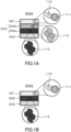
- FIG. 1A is a cross-sectional view schematically showing the structure of a battery 2000 according to Embodiment 2.
- the battery 2000 according to Embodiment 2 includes a positive electrode 201, an electrolyte layer 202, and a negative electrode 203.
- the descriptions in Embodiment 1 also apply to Embodiment 2.
- the positive electrode 201 contains a positive electrode active material 111 and a first solid electrolyte 112.
- the electrolyte layer 202 is disposed between the positive electrode 201 and the negative electrode 203.
- the electrolyte layer 202 contains a second solid electrolyte 113.
- the electrolyte layer 202 includes a first electrolyte layer 202a and a second electrolyte layer 202b.
- the first electrolyte layer 202a contains the second solid electrolyte 113.
- the second electrolyte layer 202b is located between the positive electrode 201 and the first electrolyte layer 202a and contains a third solid electrolyte 114.
- the first electrolyte layer 202a may have a thickness of 100 nm or more and 100 ⁇ m or less. When the thickness of the first electrolyte layer 202a is 100 nm or more, the occurrence of a short circuit between the positive electrode and the negative electrode can be reduced more effectively. When the thickness of the first electrolyte layer 202a is 100 ⁇ m or less, high power operation can be achieved.
- the second electrolyte layer 202b may have a thickness of 1 nm or more and 100 ⁇ m or less. When the thickness of the second electrolyte layer 202b is 1 nm or more, the oxidation of the first electrolyte layer 202a can be reliably inhibited. When the thickness of the second electrolyte layer 202b is 100 ⁇ m or less, high power operation can be achieved.
- a halide solid electrolyte may be used as the first solid electrolyte 112, the second solid electrolyte 113, and the third solid electrolyte 114.
- the halide solid electrolyte include LisYBre, Li 3 YBr 3 Cl 3 , Li 3 YBr 2 Cl 4 , Li 3 YCl 6 , and compounds obtained by substituting one or some cations in these compounds with Zr.
- the first solid electrolyte 112, the second solid electrolyte 113, and the third solid electrolyte 114 may be halide solid electrolytes having compositions that differ from each other. That is, the molar ratio of bromine in the second solid electrolyte 113 may be greater than the molar ratio of bromine in the first solid electrolyte 112.
- the first solid electrolyte 112, the second solid electrolyte 113, and the third solid electrolyte 114 may each be a mixture of solid electrolytes having compositions that differ from each other.
- a mixture of LisYBre and LiCl or a mixture of Li 3 YCl 3 Br 3 and Li 3 YCl 6 may be used.
- the first solid electrolyte 112, the second solid electrolyte 113, and the third solid electrolyte 114 may be free from sulfur.
- each of the first solid electrolyte 112, the second solid electrolyte 113, and the third solid electrolyte 114 is not limited to particular shapes, and may be, for example, an acicular shape, a spherical shape, an ellipsoidal shape, or a scale-like shape.
- the first solid electrolyte 112 may be in the form of particles.
- the second solid electrolyte 113 may be in the form of particles.
- the third solid electrolyte 114 may be in the form of particles.
- the median diameter of the group of particles of the first solid electrolyte 112 may be 100 ⁇ m or less.
- the positive electrode active material 111 and the first solid electrolyte 112 can form a favorable dispersion state in the positive electrode 201. This improves the charge and discharge characteristics of the battery 2000.
- the median diameter of the group of particles of the first solid electrolyte 112 may be 10 ⁇ m or less.
- volumetric particle size means a particle diameter when the cumulative volume in the volumetric particle size distribution is equal to 50%.
- the volumetric particle size distribution is measured using a laser diffraction measurement device or an image analysis device, for example.
- the positive electrode active material 111 contains a material having properties of occluding and releasing metal ions (e.g., lithium ions).
- metal ions e.g., lithium ions
- Examples of the positive electrode active material 111 include lithium-containing transition metal oxides, transition metal fluorides, polyanion materials, fluorinated polyanion materials, transition metal sulfides, transition metal oxysulfides, and transition metal oxynitrides.
- the battery can be produced at a low production cost and can have a high average discharge voltage.
- the positive electrode active material 111 may contain Li and at least one element selected from the group consisting of Mn, Co, Ni, and Al. Examples of such a material include Li(NiCoAl)O 2 , Li(NiCoMn)O 2 , and LiCoO 2 .
- the positive electrode active material 111 may contain one active material or a plurality of active materials having compositions that differ from each other.
- the positive electrode active material 111 may be Li(NiCoMn)O 2 .
- the positive electrode active material 111 may be in the form of particles, for example.
- the shape of the particles of the positive electrode active material 111 is not limited to particular shapes.
- the shape of the particles of the positive electrode active material 111 may be an acicular shape, a spherical shape, an ellipsoidal shape, or a scale-like shape.
- the median diameter of the particles of the first solid electrolyte 112 may be smaller than the median diameter of the particles of the positive electrode active material 111.
- the particles of the positive electrode active material 111 may have a median diameter of 0.1 ⁇ m or more and 100 ⁇ m or less.
- the positive electrode active material 111 and the first solid electrolyte 112 can form a favorable dispersion state in the positive electrode 201. As a result, the charge and discharge characteristics of the battery 2000 are improved.
- the median diameter of the particles of the positive electrode active material 111 is 100 ⁇ m or less, the lithium diffusion in the particles of the positive electrode active material 111 becomes faster. This enables high power operation of the battery 2000.
- the median diameter of the particles of the positive electrode active material 111 may be larger than the median diameter of the particles of the first solid electrolyte 112. This allows the positive electrode active material 111 and the first solid electrolyte 112 to form a favorable dispersion state.
- the positive electrode 201 may contain a plurality of particles of the first solid electrolyte 112 and a plurality of particles of the positive electrode active material 111.
- the content of the first solid electrolyte 112 and the content of the positive electrode active material 111 in the positive electrode 201 may be the same or different from each other.
- volume ratio "v1 : 100 - v1" between the positive electrode active material 111 and the first solid electrolyte 112 each contained in the positive electrode 201 30 ⁇ v1 ⁇ 95 may be satisfied.
- the battery 2000 can have a sufficient energy density.
- v1 ⁇ 95 high power operation becomes possible.
- the positive electrode 201 may have a thickness of 10 ⁇ m or more and 500 ⁇ m or less. When the thickness of the positive electrode 201 is 10 ⁇ m or more, the battery 2000 can have a sufficient energy density. When the thickness of the positive electrode 201 is 500 ⁇ m or less, high power operation becomes possible.
- the electrolyte layer 202 is a layer containing an electrolyte.
- the electrolyte is, for example, a solid electrolyte.
- the electrolyte layer 202 may be a solid electrolyte layer.
- the electrolyte layer 202 may contain, as a solid electrolyte, at least one selected from the group consisting of a halide solid electrolyte, a sulfide solid electrolyte, an oxide solid electrolyte, a polymer solid electrolyte, and a complex hydride solid electrolyte.
- any of the materials described above as specific examples of the first solid electrolyte 112, the second solid electrolyte 113, and the third solid electrolyte 114 may be used.
- the above configuration can further improve the power density and the charge and discharge characteristics of the battery 2000.
- the electrolyte layer 202 may contain a halide solid electrolyte having a composition that differs from those of the first solid electrolyte 112, the second solid electrolyte 113, and the third solid electrolyte 114. That is, the electrolyte layer 202 may contain a halide solid electrolyte having a composition that differs from that of the first solid electrolyte 112.
- the electrolyte layer 202 may include, as a third electrolyte layer, another electrolyte layer provided between the first electrolyte layer 202a and the negative electrode 203.
- Another electrolyte layer contains a fourth solid electrolyte.
- the fourth solid electrolyte include the materials described above as examples of the material that can be used as the first solid electrolyte 112, the second solid electrolyte 113, and the third solid electrolyte 114.
- first solid electrolyte 112 one of solid electrolytes to be described below as examples may be used alone, or two or more of them may be used in combination. The same applies to the second solid electrolyte 113 and the third solid electrolyte 114.
- the halide solid electrolyte is represented by, for example, the following composition formula (4).
- ⁇ , ⁇ , and ⁇ are each independently a value greater than 0.
- M includes at least one element selected from the group consisting of a metalloid element and a metal element other than Li.
- X includes at least one selected from the group consisting of F, Cl, Br, and I. Li ⁇ M ⁇ X ⁇ ... (4)
- Metalloid elements include B, Si, Ge, As, Sb, and Te.
- Metal elements include: all elements included in Groups 1 to 12 of the periodic table, except for hydrogen; and all elements included in Groups 13 to 16 of the periodic table, except for B, Si, Ge, As, Sb, Te, C, N, P, O, S, and Se.
- Metal elements are a group of elements that can be cations when they form an inorganic compound with a halogen or with a halogen compound.
- LisYXe Li 2 MgX 4 , Li 2 FeX 4 , Li(Al, Ga, In)X 4 , Li 3 (Al, Ga, In)Xs, or the like can be used.
- the above configuration can improve the power density of the battery 2000.
- the above configuration can also improve the thermal stability of the battery 2000 and can inhibit the generation of harmful gas such as hydrogen sulfide.
- X may include at least one selected from the group consisting of Cl and Br.
- the above composition can further improve the ionic conductance of the solid electrolyte. This improves the power density of the battery.
- a halide solid electrolyte containing Y may be a compound represented by the following composition formula (5). Li a M b Y c X 6 ... (5)
- M includes at least one element selected from the group consisting of a metalloid element and a metal element other than Li and Y m is the valence of M.
- X includes at least one selected from the group consisting of F, Cl, Br, and I.
- M includes at least one selected from the group consisting of Mg, Ca, Sr, Ba, Zn, Sc, Al, Ga, Bi, Zr, Hf, Ti, Sn, Ta, and Nb.
- halide solid electrolyte containing Y examples include Li 3 YF 6 , Li 3 YCl 6 , Li 3 YBr 6 , Li 3 Yl 6 , Li 3 YBrCl 5 , Li 3 YBr 3 Cl 3 , Li 3 YBr 5 Cl, Li 3 YBr 5 I, Li 3 YBr 3 I 3 , Li 3 YBrI 5 , Li 3 YClI 5 , Li 3 YCl 3 I 3 , Li 3 YCl 5 I, Li 3 YBr 2 Cl 2 I 2 , Li 3 YBrCl 4 I, Li 2.7 Y 1.1 Cl 6 , Li 2.5 Y 0.5 Zr 0.5 Cl 6 , and Li 2.5 Y 0.3 Zr 0.7 Cl 6 .
- the above configuration can further improve the power density of the battery 2000.
- Examples of the sulfide solid electrolytes include Li 2 S-P 2 S 5 , Li 2 S-SiS 2 , Li 2 S-B 2 S 3 , Li 2 S-GeS 2 , Li 3.25 Ge 0.25 P 0.75 S 4 , and Li 10 GeP 2 S 12 .
- LiX, Li 2 O, MO q , Li p MO q , or the like may be added thereto.
- the element X in “LiX” is at least one element selected from the group consisting of F, Cl, Br, and I.
- the element M in “MO q " and “Li p MO q " is at least one element selected from the group consisting of P, Si, Ge, B, Al, Ga, In, Fe, and Zn.
- p and q in "MO q " and "Li p MO q " are each independently a natural number.
- the battery 2000 configured as above includes a sulfide solid electrolyte with excellent reduction stability and thus can use a low-potential negative electrode material such as graphite or metallic lithium. Accordingly, the energy density of the battery 2000 can be improved.
- oxide solid electrolytes examples include: NASICON solid electrolytes typified by LiTi 2 (PO 4 ) 3 and element-substituted products thereof; (LaLi)TiO 3 -based perovskite solid electrolytes; LISICON solid electrolytes typified by Li 14 ZnGe 4 O 16 , Li 4 SiO 4 , and LiGeO 4 and element-substituted products thereof; garnet solid electrolytes typified by Li 7 La 3 Zr 2 O 12 and element-substituted products thereof; Li 3 N and H-substituted products thereof; Li 3 PO 4 and N-substituted products thereof; and glass and glass ceramics obtained by adding a material such as Li 2 SO 4 or Li 2 CO 3 to a base material containing a Li-B-O compound such as LiBO 2 or Li 3 BO 3 .
- NASICON solid electrolytes typified by LiTi 2 (PO 4 ) 3 and element-substituted products thereof; (
- Examples of the polymer solid electrolytes include compounds composed of a polymer compound and a lithium salt.
- the polymer compound may have an ethylene oxide structure. Since the polymer compound with the ethylene oxide structure can contain a large amount of lithium salt, this can further improve the ionic conductance.
- Examples of the lithium salt include LiPF 6 , LiBF 4 , LiSbF 6 , LiAsF 6 , LiSO 3 CF 3 , LiN(SO 2 CF 3 ) 2 , LiN(SO 2 C 2 F 5 ) 2 , LiN(SO 2 CF 3 )(SO 2 C 4 F 9 ), and LiC(SO 2 CF 3 ) 3 .
- the lithium salt one lithium salt selected from them may be used alone, or a mixture of two or more lithium salts selected from them may be used.
- Examples of the complex hydride solid electrolytes include LiBH 4 -LiI and LiBH 4 -P2S5.
- the above composition can improve the power density of the battery 2000.
- the electrolyte layer 202 may contain a solid electrolyte as a main component.
- the electrolyte layer 202 may contain 50% or more of the solid electrolyte by weight (i.e., 50 wt% or more of the solid electrolyte) with respect to the total weight of the electrolyte layer 202.
- the electrolyte layer 202 may contain 70% or more of the solid electrolyte by weight (i.e., 70 wt% or more of the solid electrolyte) with respect to the total weight of the electrolyte layer 202.
- the electrolyte layer 202 may further contain inevitable impurities, or starting materials used for synthesis of the third solid electrolyte 114, by-products, degradation products, and the like.
- the electrolyte layer 202 may contain 100% of the solid electrolyte by weight (i.e., 100 wt% of the solid electrolyte) with respect to the total weight of the electrolyte layer 202, except for inevitable impurities.
- the electrolyte layer 202 may consist of a solid electrolyte.
- the electrolyte layer 202 may contain only one solid electrolyte selected from the group of solid electrolytes described above, or may contain two or more solid electrolytes selected from the group of solid electrolytes described above.
- the plurality of solid electrolytes have compositions that differ from each other.
- the electrolyte layer 202 may contain a halide solid electrolyte and a sulfide solid electrolyte.
- the electrolyte layer 202 may have a thickness of 1 ⁇ m or more and 300 ⁇ m or less. When the thickness of the electrolyte layer 202 is 1 ⁇ m or more, the positive electrode 201 and the negative electrode 203 can be more reliably separated from each other. When the thickness of the first electrolyte layer 202 is 300 ⁇ m or less, high power operation can be achieved.
- the negative electrode 203 contains a material having properties of occluding and releasing metal ions (e.g., lithium ions).
- the negative electrode 203 contains a negative electrode active material, for example.
- a metal material As the negative electrode active material, a metal material, a carbon material, an oxide, a nitride, a tin compound, a silicon compound, or the like can be used.
- the metal material may be a single metal. Alternatively, the metal material may be an alloy.
- Examples of the metal material include lithium metal and lithium alloys.
- Examples of the carbon material include natural graphite, coke, carbon undergoing graphitization, carbon fibers, spherical carbon, artificial graphite, and amorphous carbon. From the viewpoint of capacity density, silicon (Si), tin (Sn), a silicon compound, or a tin compound may be used.
- the negative electrode 203 may contain a solid electrolyte.
- the above configuration improves the lithium ion conductivity inside the negative electrode 203, whereby high power operation becomes possible.
- the solid electrolyte the materials described above may be used.
- the particles of the negative electrode active material may have a median diameter of 0.1 ⁇ m or more and 100 ⁇ m or less.
- the median diameter of the particles of the negative electrode active material is 0.1 ⁇ m or more, the negative electrode active material and the solid electrolyte can form a favorable dispersion state in the negative electrode 203. This improves the charge and discharge characteristics of the battery 2000.
- the median diameter of the particles of the negative electrode active material is 100 ⁇ m or less, the lithium diffusion in the particles of the negative electrode active material becomes faster. This enables high power operation of the battery 2000.
- the median diameter of the particles of the negative electrode active material may be larger than the median diameter of particles of the solid electrolyte contained in the negative electrode 203. This allows the negative electrode active material and the solid electrolyte to form a favorable dispersion state.
- the volume ratio between the negative electrode active material and the solid electrolyte in the negative electrode 203 is expressed as "v2 : 100 - v2"
- the volume ratio v2 of the negative electrode active material may satisfy 30 ⁇ v2 ⁇ 95.
- the battery 2000 can have a sufficient energy density.
- v2 ⁇ 95 is satisfied, high power operation becomes possible.
- the negative electrode 203 may have a thickness of 10 ⁇ m or more and 500 ⁇ m or less. When the thickness of the negative electrode 203 is 10 ⁇ m or more, the battery 2000 can have a sufficient energy density. When the thickness of the negative electrode 203 is 500 ⁇ m or less, high power operation becomes possible.
- At least one of the positive electrode 201, the electrolyte layer 202, and the negative electrode 203 may contain a binder to improve the adhesion between particles.
- the binder is used to improve the binding properties of the materials constituting the electrodes.
- the binder include polyvinylidene fluoride, polytetrafluoroethylene, polyethylene, polypropylene, aramid resin, polyamide, polyimide, polyamide-imide, polyacrylonitrile, polyacrylic acid, poly(acrylic acid methyl ester), poly(acrylic acid ethyl ester), poly(acrylic acid hexyl ester), polymethacrylic acid, poly(methacrylic acid methyl ester), poly(methacrylic acid ethyl ester), poly(methacrylic acid hexyl ester), polyvinyl acetate, polyvinylpyrrolidone, polyether, polyether sulfone, hexafluoropolypropylene, sty
- the binder may be a copolymer of two or more materials selected from tetrafluoroethylene, hexafluoroethylene, hexafluoropropylene, perfluoroalkyl vinyl ether, vinylidene fluoride, chlorotrifluoroethylene, ethylene, propylene, pentafluoropropylene, fluoromethyl vinyl ether, acrylic acid, and hexadiene.
- the binder may be a mixture of two or more materials selected from them.
- At least one of the positive electrode 201 and the negative electrode 203 may contain a conductive additive to improve the electronic conductivity.
- the conductive additive include: graphite such as natural graphite and artificial graphite; carbon blacks such as acetylene black and Ketjen black; conductive fibers such as carbon fibers and metal fibers; carbon fluoride; metal powders such as aluminum powder; conductive whiskers such as zinc oxide whiskers and potassium titanate whiskers; conductive metal oxides such as titanium oxide; and conductive polymer compounds such as polyaniline, polypyrrole, and polythiophene. Cost reduction can be achieved by using a carbon conductive additive.
- the battery 2000 of Embodiment 2 can be embodied as batteries with various shapes, including a coin battery, a cylindrical battery, a prismatic battery, a sheet-like battery, a button battery, a flat-type battery, and a stacked battery.
- FIG. 1B is a cross-sectional view schematically showing the structure of a battery 3000 according to a modification.
- the battery 3000 includes a positive electrode 201, a negative electrode 203, and an electrolyte layer 202.
- the electrolyte layer 202 corresponds to the first electrolyte layer 202a described in Embodiment 2. That is, the battery 3000 has the same structure as the battery 2000, except that it does not include the second electrolyte layer 202b. Unless technically incompatible, the above descriptions regarding the battery 2000 also apply to the battery 3000.
- this solid electrolyte is referred to as "LYB”.
- LYB and acetylene black were prepared at a mass ratio of 93 : 7. They were mixed together in an agate mortar to produce a mixed material.
- sulfide solid electrolyte 80 mg of a sulfide solid electrolyte, 20 mg of LYB, and 5 mg of the above-described mixed material were stacked in this order in an insulating outer cylinder.
- sulfide solid electrolyte Li 6 PS 5 Cl powder was used.
- a pressure of 720 MPa was applied to the thus-obtained stack.
- an In-Li foil was stacked on the layer of the sulfide solid electrolyte.
- a pressure of 80 MPa was applied to the stack composed of the mixed material, the electrolyte layer, and the negative electrode.
- An evaluation battery 1 for evaluating the oxidation potential of Br was thus obtained.
- the stacking structure of the evaluation battery 1 was as follows: (LYB + acetylene black)/LYB/sulfide solid electrolyte layer/In-Li.
- this solid electrolyte is referred to as "LYBC”.
- An evaluation battery 2 was produced in the same manner as the evaluation battery 1, except that LYBC was used.
- the stacking structure of the evaluation battery 2 was as follows: (LYBC + acetylene black)/LYBC/sulfide solid electrolyte layer/In-Li.
- this solid electrolyte is referred to as "LYC”.
- An evaluation battery 3 was produced in the same manner as the evaluation battery 1, except that LYC was used.
- the stacking structure of the evaluation battery 3 was as follows: (LYC + acetylene black)/LYC/sulfide solid electrolyte layer/In-Li.
- Each of the evaluation batteries was subjected to linear sweep voltammetry (LSV) measurement.
- LSV linear sweep voltammetry
- the battery was placed in a thermostatic chamber set at 25°C.
- the evaluation battery was connected to a potentio-galvanostat to perform LSV measurement.
- the LSV measurement was performed with the sweep rate set to 10 mV/s.
- the scanning range was set from the open circuit voltage (OCV) to 4.0 V vs. In-Li.
- OCV open circuit voltage
- In-Li In the LSV measurement, the current responses obtained when the potential was swept from the OCV to 4.0 V were plotted.
- FIG. 2 is a graph showing the results of the LSV measurement.
- LSV measurement when the swept potential reaches a certain potential, a solid electrolyte is oxidized at that potential, thereby causing a current to flow.
- LYB had an oxidation potential of 2.9 V vs. In-Li.
- LYBC had an oxidation potential of 3.1 V vs. In-Li.
- LYC had an oxidation potential of 3.5 V vs. In-Li.
- the oxidation current rose up in the vicinity of 2.9 V to 3.1 V, and this revealed that the oxidation potential of Br in the solid electrolyte is in this range.
- the oxidation potential vs. Li of Br in the solid electrolyte can be calculated by adding 0.6 V (the potential of In-Li alloy vs. Li) to the potential of LYB (2.9 V). That is, according to the results obtained using the evaluation battery 1 (LYB), the oxidation potential of Br in the solid electrolyte versus Li potential was 3.5 V.
- LYC had an oxidation potential of 3.5 V vs. In-Li.
- the oxidation potential of 3.5 V is equivalent to the potential vs. Li of 4.1 V. That is, it is considered that, in the case of the solid electrolyte containing Cl, long-time exposure to a potential of 4.1 V or more causes oxidization of Cl in the solid electrolyte, leading to collapse of the structure of the solid electrolyte.
- a suitable potential for allowing debromination of a solid electrolyte containing Br to proceed is in the range of more than 3.5 V and less than 4.1 V relative to the potential of Li.
- the point at which the current value reached 0.05 mA was regarded as the oxidation potential of each of the solid electrolytes.
- the rise of an oxidation current varies depending on the temperature at which measurement is performed, conditions under which an evaluation battery is produced, and the like. Therefore, the oxidation potential determined in this measurement is considered to have an error margin of about ⁇ 0.2 V.
- LYB had an oxidation potential of 2.9 V vs. In-Li.
- LYBC had an oxidation potential of 3.1 V vs. In-Li.
- NCM Li(Ni, Co, Mn)O 2
- LYBC a solid electrolyte
- VGCF vapor grown carbon fibers
- a sulfide solid electrolyte 80 mg of a sulfide solid electrolyte, 20 mg of LYBC, and 19.5 mg of the above-described positive electrode mixture were stacked in this order in an insulating outer cylinder.
- As the sulfide solid electrolyte Li 6 PS 5 Cl powder was used. A pressure of 720 MPa was applied to the thus-obtained stack, whereby a positive electrode and an electrolyte layer were obtained.
- a Li foil was placed on a surface of the electrolyte layer opposite to a surface in contact with the positive electrode.
- a pressure of 80 MPa was applied to the positive electrode, the electrolyte layer, and the Li foil, whereby a stack composed of the positive electrode, the electrolyte layer, and a negative electrode was produced.
- the debromination treatment includes charging the stack with a constant volage that is equal to or higher than the voltage at which the potential of the positive electrode is equal to the oxidation potential of bromine contained in the solid electrolyte.
- the debromination treatment includes charging the stack with a constant current to a voltage at which the potential of the positive electrode is equal to the oxidation potential of bromine contained in the solid electrolyte and charging the stack with a constant volage that is equal to or higher than the voltage at which the potential of the positive electrode is equal to the oxidation potential of bromine contained in the solid electrolyte.
- the voltage in the constant voltage charging may be equal to or higher than the voltage at which the potential of the positive electrode is equal to the oxidation potential of the bromine contained in the solid electrolyte and lower than the battery voltage at which the potential of the positive electrode is equal to the oxidation potential of chlorine.
- a secondary battery of the example was thus produced.
- a secondary battery was produced in the same manner as in the example, except that the debromination treatment was not performed.
- the secondary battery of the example was disassembled, and a power generating element, which includes the positive electrode, the electrolyte, and the negative electrode, was taken out from the insulating outer cylinder.
- the power generating element was cut in the thickness direction, and the cross-section was then smoothed by argon ion milling. Thereafter, the composition near the interface between the positive electrode and the electrolyte layer was analyzed using a field emission scanning electron microscope-energy dispersive X-ray analyzer (FE-SEM-EDX) to determine c1, c2, c3, d1, d2, d3, e1, e2, and e3 in the composition formulae (1), (2), and (3).
- FE-SEM-EDX field emission scanning electron microscope-energy dispersive X-ray analyzer
- FIG. 4 is a SEM image showing a cross-section of the positive electrode and electrolyte layer having been subjected to the debromination treatment.
- FIG. 5A is a graph showing the ratio of each type of anion present in a portion indicated with the dashed line in FIG. 4 .
- the secondary battery of each of the example and the comparative example was placed in a thermostatic chamber set at 25°C.
- the secondary battery was charged with a constant current of 0.140 mA, and the charging was terminated when the voltage reached 4.3 V.
- the secondary battery was discharged also with a current of 0.140 mA, and the discharging was terminated when the voltage reached 2.5 V.
- the results are shown in Table 1 and FIG. 3 .
- Table 1 shows the charge and discharge efficiencies of the secondary batteries of the example and the comparative example.
- the charge and discharge efficiency of the secondary battery of the comparative example was 90%.
- the charge and discharge efficiency of the secondary battery of the example was 92%.
- the debromination treatment improved the charge and discharge efficiency.
- the charge and discharge efficiency in this case refers to a value obtained by dividing the initial discharge capacity by the initial charge capacity.
- [Table 1] Debromination treatment Charge and discharge efficiency (%) Comparative Example Not Performed 90
- FIG. 3 is a graph showing discharge curves of the secondary batteries of the example and the comparative example during the initial discharging. As can be seen from FIG. 3 , there was no noticeable difference between the discharge curve of the example and the discharge curve of the comparative example. That is to say, the debromination treatment did not have much effect on the discharge curve during the initial discharging.
- the cross-section of the secondary battery of the example was analyzed using the EDX to examine the composition of a portion extending from the electrolyte layer to the positive electrode. The results are shown in FIGs. 5A and 5B .
- FIG. 5A is a graph showing the ratio of each type of anion present in the portion indicated with the dashed line in FIG. 4 in terms of atomic ratio.
- FIG. 5B is a fragmentary enlarged view of FIG. 5A .
- the anions are oxygen, bromine, and chlorine.
- the ratio of each anion was calculated from the composition ratio measured using the EDX.
- the regions used for the calculation were regions 1, 2, and 3 shown in FIGs. 5A and 5B . These regions each had a width of 1 ⁇ m.
- the ratio of Br anion was calculated using average values of data obtained at a plurality of points in each region. Table 2 shows the results thereof.
- the definitions of ⁇ 1, ⁇ 2, ⁇ 3, ⁇ 1, ⁇ 2 and ⁇ 3 in Table 2 are as follows.
- the solid electrolyte contained in the positive electrode is defined as the first solid electrolyte.
- the solid electrolytes contained in the electrolyte layer are defined as a second solid electrolyte (on the negative electrode side) and a third solid electrolyte (on the positive electrode side).
- the total amount of substance of the anions in the first solid electrolyte is defined as ⁇ 1
- the amount of substance of a bromine anion in the first solid electrolyte is defined as ⁇ 1.
- the total amount of substance of the anions in the second solid electrolyte is defined as ⁇ 2, and the amount of substance of a bromine anion in the second solid electrolyte is defined as ⁇ 2.
- the total amount of substance of the anions in the third solid electrolyte is defined as ⁇ 3, and the amount of substance of a bromine anion in the third solid electrolyte is defined as ⁇ 3.
- the molar ratio of Br to the anions contained in the solid electrolyte (first solid electrolyte) in the positive electrode was 0.19.
- the molar ratio of Br to the anions contained in each of the solid electrolytes used in the electrolyte layer was 0.36 or 0.30. That is, the molar ratio of Br to the anions contained in the solid electrolyte (first solid electrolyte) in the positive electrode was smaller than the molar ratio of Br to the anions contained in the solid electrolyte (second solid electrolyte) used in the electrolyte layer.
- the relationship ⁇ 1/ ⁇ 1 ⁇ ⁇ 2/ ⁇ 2 was satisfied in the graphs of FIGs. 5A and 5B .
- the region 1 corresponds to the first electrolyte layer 202a described with reference to FIG. 1A and contained the second solid electrolyte.
- the region 2 corresponds to the second electrolyte layer 202b described with reference to FIG. 1A and contained the third solid electrolyte. Note here that the solid electrolyte used in the region 1 and the solid electrolyte used in the region 2 initially had the same composition.
- the composition of the electrolyte layer changed gradually toward the interface between the electrolyte layer and the positive electrode. That is, the molar ratio of Br to the anions contained in the region 2 corresponding to the second electrolyte layer was smaller than the molar ratio of Br to the anions contained in the region 1 corresponding to the first electrolyte layer. In other words, the relationship ⁇ 1/ ⁇ 1 ⁇ ⁇ 3/ ⁇ 3 ⁇ ⁇ 2/ ⁇ 2 was satisfied in the graphs of FIGs. 5A and 5B .
- the molar ratio of Br gradually decreased. That is, in the region 2 corresponding to the second electrolyte layer, the ratio ⁇ 3/ ⁇ 3 on the positive electrode side was lower than the ratio ⁇ 3/ ⁇ 3 on the first electrolyte layer side.
- the graphs shown in FIGs. 5A and 5B are normalized such that the total amount of substance of anions is 1.
- Oxygen is not an element contained in the raw materials used to produce the solid electrolytes. It is considered that the oxygen is an element that was derived from oxygen gas in the air, water in the air, and the positive electrode active material, and unavoidably contained in the solid electrolytes. There is a possibility that the debromination treatment might have promoted the introduction of oxygen into the solid electrolytes.
- EDX measurement of the secondary battery of the comparative example was performed in the same manner as that for the secondary battery of the example. Thereafter, the molar ratio of bromine to the total amount of bromine and chlorine in each of the electrolyte layer and the positive electrode was calculated. Also for the secondary battery of the example, the molar ratio of bromine to the total amount of bromine and chlorine in each of the electrolyte layer and the positive electrode was calculated. The reason why oxygen was not used in the calculation was to compare the example and the comparative example in a state where the effect of oxygen derived from the positive electrode active material was eliminated.
- the atomic ratio of Br to the total amount of Br and Cl in the electrolyte layer was approximately the same as the atomic ratio of Br to the total amount of Br and Cl in the positive electrode.
- the atomic ratio of Br to the total amount of Br and Cl in the solid electrolyte contained in the positive electrode was much lower than the atomic ratio of Br to the total amount of Br and Cl in the electrolyte layer. The reason for this is considered to be that the debromination treatment reduced the concentration of bromine in the solid electrolyte contained in the positive electrode.
- the battery of the present disclosure can be utilized as, for example, an all-solid-state secondary battery.
Landscapes
- Chemical & Material Sciences (AREA)
- Engineering & Computer Science (AREA)
- Manufacturing & Machinery (AREA)
- Chemical Kinetics & Catalysis (AREA)
- Electrochemistry (AREA)
- General Chemical & Material Sciences (AREA)
- Physics & Mathematics (AREA)
- Condensed Matter Physics & Semiconductors (AREA)
- General Physics & Mathematics (AREA)
- Inorganic Chemistry (AREA)
- Secondary Cells (AREA)
- Battery Electrode And Active Subsutance (AREA)
Applications Claiming Priority (2)
| Application Number | Priority Date | Filing Date | Title |
|---|---|---|---|
| JP2020074516 | 2020-04-20 | ||
| PCT/JP2021/014087 WO2021215215A1 (ja) | 2020-04-20 | 2021-03-31 | 電池 |
Publications (1)
| Publication Number | Publication Date |
|---|---|
| EP4141995A1 true EP4141995A1 (de) | 2023-03-01 |
Family
ID=78270726
Family Applications (1)
| Application Number | Title | Priority Date | Filing Date |
|---|---|---|---|
| EP21793707.7A Withdrawn EP4141995A1 (de) | 2020-04-20 | 2021-03-31 | Batterie |
Country Status (5)
| Country | Link |
|---|---|
| US (1) | US12537223B2 (de) |
| EP (1) | EP4141995A1 (de) |
| JP (1) | JP7804863B2 (de) |
| CN (1) | CN115428216A (de) |
| WO (1) | WO2021215215A1 (de) |
Families Citing this family (1)
| Publication number | Priority date | Publication date | Assignee | Title |
|---|---|---|---|---|
| KR20240074518A (ko) * | 2022-11-21 | 2024-05-28 | 재단법인 포항산업과학연구원 | 고체 전해질 시트, 이의 제조방법 및 이를 포함하는 리튬 이차 전지 |
Family Cites Families (6)
| Publication number | Priority date | Publication date | Assignee | Title |
|---|---|---|---|---|
| JP5108205B2 (ja) | 2005-02-28 | 2012-12-26 | 国立大学法人静岡大学 | 全固体型リチウム二次電池 |
| JP6531674B2 (ja) * | 2016-02-26 | 2019-06-19 | トヨタ自動車株式会社 | 硫化物固体電解質材料、リチウム固体電池および硫化物固体電解質材料の製造方法 |
| CN111587508A (zh) | 2018-01-26 | 2020-08-25 | 松下知识产权经营株式会社 | 电池 |
| EP3745518B1 (de) * | 2018-01-26 | 2022-04-13 | Panasonic Intellectual Property Management Co., Ltd. | Batterie |
| EP3745499A4 (de) | 2018-01-26 | 2021-03-24 | Panasonic Intellectual Property Management Co., Ltd. | Positivelektrodenmaterial und batterie |
| JP7348170B2 (ja) | 2018-09-27 | 2023-09-20 | 三井金属鉱業株式会社 | 活物質、それを用いた正極合剤及び全固体電池 |
-
2021
- 2021-03-31 JP JP2022516925A patent/JP7804863B2/ja active Active
- 2021-03-31 WO PCT/JP2021/014087 patent/WO2021215215A1/ja not_active Ceased
- 2021-03-31 EP EP21793707.7A patent/EP4141995A1/de not_active Withdrawn
- 2021-03-31 CN CN202180028245.3A patent/CN115428216A/zh active Pending
-
2022
- 2022-10-14 US US17/966,436 patent/US12537223B2/en active Active
Also Published As
| Publication number | Publication date |
|---|---|
| US20230067002A1 (en) | 2023-03-02 |
| JP7804863B2 (ja) | 2026-01-23 |
| WO2021215215A1 (ja) | 2021-10-28 |
| US12537223B2 (en) | 2026-01-27 |
| JPWO2021215215A1 (de) | 2021-10-28 |
| CN115428216A (zh) | 2022-12-02 |
Similar Documents
| Publication | Publication Date | Title |
|---|---|---|
| US12183927B2 (en) | Electrode material and battery | |
| US11404718B2 (en) | Solid electrolyte material and battery | |
| US11749803B2 (en) | Cathode material and battery | |
| EP4123754A1 (de) | Positivelektrodenmaterial und batterie | |
| US20200328461A1 (en) | Solid electrolyte material and battery | |
| EP4123746B1 (de) | Festelektrolytmaterial und zelle damit | |
| US12272786B2 (en) | Solid electrolyte material and battery using same | |
| WO2019146294A1 (ja) | 電池 | |
| WO2019146217A1 (ja) | 電池 | |
| US20220384843A1 (en) | Solid electrolyte material and battery using same | |
| WO2021002064A1 (ja) | 電池 | |
| US12494505B2 (en) | Solid electrolyte material and battery in which same is used | |
| JPWO2020174868A1 (ja) | 正極材料、および、電池 | |
| US20230055771A1 (en) | Solid electrolyte material and battery using same | |
| US20230103996A1 (en) | Solid electrolyte material, and battery in which same is used | |
| US12456732B2 (en) | Negative electrode material and battery | |
| US12537223B2 (en) | Battery | |
| US20240413393A1 (en) | Solid electrolyte material and battery using same | |
| US20240291026A1 (en) | Battery | |
| EP4468391A1 (de) | Batterie | |
| US12609348B2 (en) | Solid electrolyte material and battery using same | |
| US20240145770A1 (en) | Battery | |
| US20240283014A1 (en) | Positive electrode material and battery | |
| US20220328804A1 (en) | Electrode and battery | |
| US20220320481A1 (en) | Electrode and battery |
Legal Events
| Date | Code | Title | Description |
|---|---|---|---|
| STAA | Information on the status of an ep patent application or granted ep patent |
Free format text: STATUS: THE INTERNATIONAL PUBLICATION HAS BEEN MADE |
|
| PUAI | Public reference made under article 153(3) epc to a published international application that has entered the european phase |
Free format text: ORIGINAL CODE: 0009012 |
|
| STAA | Information on the status of an ep patent application or granted ep patent |
Free format text: STATUS: REQUEST FOR EXAMINATION WAS MADE |
|
| 17P | Request for examination filed |
Effective date: 20220929 |
|
| AK | Designated contracting states |
Kind code of ref document: A1 Designated state(s): AL AT BE BG CH CY CZ DE DK EE ES FI FR GB GR HR HU IE IS IT LI LT LU LV MC MK MT NL NO PL PT RO RS SE SI SK SM TR |
|
| DAV | Request for validation of the european patent (deleted) | ||
| DAX | Request for extension of the european patent (deleted) | ||
| STAA | Information on the status of an ep patent application or granted ep patent |
Free format text: STATUS: THE APPLICATION HAS BEEN WITHDRAWN |
|
| 18W | Application withdrawn |
Effective date: 20230906 |