EP4142399A1 - Procédé et dispositif permettant de configurer une bwp pour une continuité de service de mbs dans un système de communication sans fil - Google Patents
Procédé et dispositif permettant de configurer une bwp pour une continuité de service de mbs dans un système de communication sans fil Download PDFInfo
- Publication number
- EP4142399A1 EP4142399A1 EP21804335.4A EP21804335A EP4142399A1 EP 4142399 A1 EP4142399 A1 EP 4142399A1 EP 21804335 A EP21804335 A EP 21804335A EP 4142399 A1 EP4142399 A1 EP 4142399A1
- Authority
- EP
- European Patent Office
- Prior art keywords
- mbs
- bwp
- configuration information
- rrc
- terminal
- Prior art date
- Legal status (The legal status is an assumption and is not a legal conclusion. Google has not performed a legal analysis and makes no representation as to the accuracy of the status listed.)
- Pending
Links
Images





Classifications
-
- H—ELECTRICITY
- H04—ELECTRIC COMMUNICATION TECHNIQUE
- H04W—WIRELESS COMMUNICATION NETWORKS
- H04W72/00—Local resource management
- H04W72/30—Resource management for broadcast services
-
- H—ELECTRICITY
- H04—ELECTRIC COMMUNICATION TECHNIQUE
- H04L—TRANSMISSION OF DIGITAL INFORMATION, e.g. TELEGRAPHIC COMMUNICATION
- H04L5/00—Arrangements affording multiple use of the transmission path
- H04L5/0091—Signalling for the administration of the divided path, e.g. signalling of configuration information
- H04L5/0092—Indication of how the channel is divided
-
- H—ELECTRICITY
- H04—ELECTRIC COMMUNICATION TECHNIQUE
- H04W—WIRELESS COMMUNICATION NETWORKS
- H04W4/00—Services specially adapted for wireless communication networks; Facilities therefor
- H04W4/06—Selective distribution of broadcast services, e.g. multimedia broadcast multicast service [MBMS]; Services to user groups; One-way selective calling services
-
- H—ELECTRICITY
- H04—ELECTRIC COMMUNICATION TECHNIQUE
- H04W—WIRELESS COMMUNICATION NETWORKS
- H04W76/00—Connection management
- H04W76/40—Connection management for selective distribution or broadcast
-
- H—ELECTRICITY
- H04—ELECTRIC COMMUNICATION TECHNIQUE
- H04W—WIRELESS COMMUNICATION NETWORKS
- H04W72/00—Local resource management
- H04W72/04—Wireless resource allocation
- H04W72/044—Wireless resource allocation based on the type of the allocated resource
- H04W72/0453—Resources in frequency domain, e.g. a carrier in FDMA
-
- H—ELECTRICITY
- H04—ELECTRIC COMMUNICATION TECHNIQUE
- H04W—WIRELESS COMMUNICATION NETWORKS
- H04W72/00—Local resource management
- H04W72/20—Control channels or signalling for resource management
- H04W72/23—Control channels or signalling for resource management in the downlink direction of a wireless link, i.e. towards a terminal
-
- H—ELECTRICITY
- H04—ELECTRIC COMMUNICATION TECHNIQUE
- H04W—WIRELESS COMMUNICATION NETWORKS
- H04W76/00—Connection management
- H04W76/10—Connection setup
- H04W76/11—Allocation or use of connection identifiers
-
- H—ELECTRICITY
- H04—ELECTRIC COMMUNICATION TECHNIQUE
- H04W—WIRELESS COMMUNICATION NETWORKS
- H04W76/00—Connection management
- H04W76/20—Manipulation of established connections
- H04W76/27—Transitions between radio resource control [RRC] states
-
- Y—GENERAL TAGGING OF NEW TECHNOLOGICAL DEVELOPMENTS; GENERAL TAGGING OF CROSS-SECTIONAL TECHNOLOGIES SPANNING OVER SEVERAL SECTIONS OF THE IPC; TECHNICAL SUBJECTS COVERED BY FORMER USPC CROSS-REFERENCE ART COLLECTIONS [XRACs] AND DIGESTS
- Y02—TECHNOLOGIES OR APPLICATIONS FOR MITIGATION OR ADAPTATION AGAINST CLIMATE CHANGE
- Y02D—CLIMATE CHANGE MITIGATION TECHNOLOGIES IN INFORMATION AND COMMUNICATION TECHNOLOGIES [ICT], I.E. INFORMATION AND COMMUNICATION TECHNOLOGIES AIMING AT THE REDUCTION OF THEIR OWN ENERGY USE
- Y02D30/00—Reducing energy consumption in communication networks
- Y02D30/70—Reducing energy consumption in communication networks in wireless communication networks
Definitions
- the disclosure relates to a wireless communication system, and more particularly, to a method and apparatus for configuring a bandwidth part (BWP) for multicast and broadcast service (MBS) continuity in a wireless communication system.
- BWP bandwidth part
- MMS broadcast service
- 5G or pre-5G communication systems are called 'beyond 4G network' communication systems or 'post long term evolution (post-LTE)' systems.
- mmWave millimeter-wave
- ACM advanced coding modulation
- FQAM quadrature amplitude modulation
- SWSC sliding window superposition coding
- FBMC filter bank multi-carrier
- NOMA non-orthogonal multiple access
- SCMA sparse code multiple access
- the Internet has evolved from a human-based connection network, where humans create and consume information, to the Internet of things (loT), where distributed elements such as objects exchange information with each other to process the information.
- Internet of everything (loE) technology has emerged, in which the loT technology is combined with, for example, technology for processing big data through connection with a cloud server.
- various technological elements such as sensing technology, wired/wireless communication and network infrastructures, service interface technology, and security technology are required and, in recent years, technologies related to sensor networks, machine-to-machine (M2M) communication, and machine-type communication (MTC) for connecting objects have been studied.
- M2M machine-to-machine
- MTC machine-type communication
- intelligent Internet technology (IT) services may be provided to collect and analyze data obtained from connected objects to create new value in human life.
- IT information technology
- the loT may be applied to various fields such as smart homes, smart buildings, smart cities, smart cars or connected cars, smart grids, health care, smart home appliances, and advanced medical services.
- 5G communication systems to the loT network.
- technologies related to sensor networks, M2M communication, and MTC communication are being implemented by using 5G communication technology including beamforming, MIMO, and array antennas.
- Application of a cloud RAN as the above-described big data processing technology may be an example of convergence of 5G communication technology and loT technology.
- MMS multicast and broadcast service
- a terminal for receiving multicast and broadcast service (MBS) in a wireless communication system may be provided.
- the terminal may receive, from a base station, bandwidth part (BWP) configuration information for receiving MBS, the BWP configuration information including at least one of a BWP identity, temporary mobile group identities (TMGls) of MBS services provided in a BWP, or a group-radio network temporary identity (G-RNTI), or supplementary downlink (SDL) carrier configuration information for receiving MBS, the SDL carrier configuration information including at least one of an SDL carrier identity, a physical-layer cell identity (PCI), or a SDL configuration indicator, and receive first MBS data in a BWP corresponding to the BWP configuration information for receiving MBS or an SDL carrier corresponding to the SDL carrier configuration information for receiving MBS, in a radio resource control (RRC) idle mode or an RRC inactive mode, based on the received BWP configuration information or SDL carrier configuration information.
- BWP bandwidth part
- TMGls
- an operating method of a base station for transmitting multicast and broadcast service (MBS) in a wireless communication system may include determining a bandwidth part (BWP) for MBS reception by a terminal, including configuration information of the determined BWP in at least one of a system information block (SIB), a radio resource control (RRC) release message, or an RRC reconfiguration message and transmitting the configuration information to the terminal, and transmitting MBS services to the terminal by using the determined BWP.
- SIB system information block
- RRC radio resource control
- an operating method of a terminal for receiving multicast and broadcast service (MBS) in a wireless communication system may include receiving, from a base station, configuration information of a BWP for MBS reception by the terminal of a radio resource control (RRC) idle mode or an RRC inactive mode, and receiving MBS services from the base station, based on the configuration information of the BWP, wherein the configuration information of the BWP for MBS reception may be included and received in at least one of a system information block (SIB), an RRC release message, or an RRC reconfiguration message.
- SIB system information block
- RRC release message an RRC release message
- a terminal for receiving multicast and broadcast service (MBS) in a wireless communication system may include a transceiver, and at least one processor configured to receive, from a base station, bandwidth part (BWP) configuration information for receiving MBS, the BWP configuration information including at least one of a BWP identity, temporary mobile group identities (TMGls) of MBS services provided in a BWP, or a group-radio network temporary identity (G-RNTI), or supplementary downlink (SDL) carrier configuration information for receiving MBS, the SDL carrier configuration information including at least one of an SDL carrier identity, a physical-layer cell identity (PCI), or a SDL configuration indicator, and receive first MBS data in a BWP corresponding to the BWP configuration information for receiving MBS or an SDL carrier corresponding to the SDL carrier configuration information for receiving MBS, in a radio resource control (RRC) idle mode or an RRC inactive mode, based on the received BWP configuration information
- RRC radio resource control
- At least one of the BWP configuration information for receiving MBS or the SDL carrier configuration information for receiving MBS may be included and transmitted in a system information block (SIB) or an RRC release message.
- SIB system information block
- the BWP configuration information for receiving MBS may further include at least one of search space information or control resource set (CORESET) information for a physical downlink control channel (PDCCH) to be monitored to receive the first MBS data.
- CORESET control resource set
- the BWP configuration information for receiving MBS may include the DL BWP configuration information including the G-RNTI, and the at least one processor may be further configured to determine a DL radio resource for receiving MBS in a DL BWP corresponding to the received DL BWP configuration information, by using the G-RNTI, and receive the first MBS data in the determined DL radio resource.
- the BWP configuration information for receiving MBS may include the DL BWP configuration information including the G-RNTI, and the at least one processor may be further configured to determine a DL radio resource in the initial BWP, by using the G-RNTI, and receive the first MBS data in a DL BWP corresponding to the DL BWP configuration information.
- the at least one processor may be further configured to transmit, to the base station, at least one of an RRC connection request message or an RRC resume request message including MBS information for the first MBS data, receive, from the base station, configuration information for second MBS data receivable in an RRC connected mode, and receive the second MBS data in the RRC connected mode, based on the configuration information for the second MBS data, and the MBS information for the first MBS data may include at least one of TMGls of MBS services being received by the terminal in the RRC idle mode or the RRC inactive mode, an indicator indicating that the MBS services are desired to be continuously received in the RRC connected mode, a list of MBS services desired to be continuously received in the RRC connected mode, or a list of MBS services no longer desired to be received.
- the SDL carrier configuration information for receiving MBS may include an identity of the SDL carrier, or a list of MBS services being provided in the SDL carrier.
- the base station may operate a first BWP providing MBS services that the terminal desires to receive, and a second BWP not providing the MBS services that the terminal desires to receive
- the at least one processor may be further configured to receive, from the base station, information about MBS services provided in each of the first and second BWPs, or information about the first BWP, and the information about the MBS services provided in each of the first and second BWPs, or the information about the first BWP may be included and transmitted in at least one of an RRC reconfiguration message, an RRC setup message, an RRC reestablishment message, an RRC release message, or a SIB.
- a base station for providing multicast and broadcast service (MBS) in a wireless communication system may include a transceiver, and at least one processor configured to transmit, to a terminal of a radio resource control (RRC) idle mode or an RRC inactive mode, bandwidth part (BWP) configuration information for providing MBS, the BWP configuration information including at least one of a BWP identity, temporary mobile group identities (TMGls) of MBS services provided in a BWP, or a group-radio network temporary identity (G-RNTI), or supplementary downlink (SDL) carrier configuration information for providing MBS, the SDL carrier configuration information including at least one of an SDL carrier identity, a physical-layer cell identity (PCI), or a SDL configuration indicator, and transmit, to the terminal, first MBS data in a BWP corresponding to the BWP configuration information for providing MBS or an SDL carrier corresponding to the SDL carrier configuration information for providing MBS, based on the transmitted
- RRC radio resource control
- BWP bandwidth part
- the at least one processor may be further configured to receive, from the terminal, at least one of an RRC connection request message or an RRC resume request message including MBS information for the first MBS data, transmit, to the terminal, configuration information for second MBS data receivable in an RRC connected mode, and transmit the second MBS data in the RRC connected mode to the terminal of the RRC connected mode, based on the configuration information for the second MBS data, and the MBS information for the first MBS data may include at least one of TMGls of MBS services being received by the terminal in the RRC idle mode or the RRC inactive mode, an indicator indicating that the MBS services are desired to be continuously received in the RRC connected mode, a list of MBS services desired to be continuously received in the RRC connected mode, or a list of MBS services no longer desired to be received.
- the base station may operate a first BWP providing MBS services that the terminal desires to receive, and a second BWP not providing the MBS services that the terminal desires to receive
- the at least one processor may be further configured to transmit, to the terminal, information about MBS services provided in each of the first and second BWPs, or information about the first BWP, and the information about the MBS services provided in each of the first and second BWPs, or the information about the first BWP may be included and transmitted in at least one of an RRC reconfiguration message, an RRC setup message, an RRC reestablishment message, an RRC release message, or a SIB.
- blocks in flowcharts or combinations of the flowcharts may be performed by computer program instructions. Because these computer program instructions may be loaded into a processor of a general-purpose computer, a special-purpose computer, or another programmable data processing apparatus, the instructions, which are performed by a processor of a computer or another programmable data processing apparatus, create units for performing functions described in the flowchart block(s).
- the computer program instructions may be stored in a computer-usable or computer-readable memory capable of directing a computer or another programmable data processing apparatus to implement a function in a particular manner, and thus the instructions stored in the computer-usable or computer-readable memory may produce manufacturing items containing instruction units for performing the functions described in the flowchart block(s).
- the computer program instructions may also be loaded into a computer or another programmable data processing apparatus, and thus, instructions for operating the computer or the other programmable data processing apparatus by generating a computer-executed process when a series of operations are performed in the computer or the other programmable data processing apparatus may provide operations for performing the functions described in the flowchart block(s).
- each block may represent a portion of a module, segment, or code that includes one or more executable instructions for executing specified logical function(s). It is also noted that, in some alternative implementations, functions mentioned in blocks may occur out of order. For example, two consecutive blocks may also be executed simultaneously or in reverse order depending on functions corresponding thereto.
- the term “unit” denotes a software element or a hardware element such as a field-programmable gate array (FPGA) or an application-specific integrated circuit (ASIC), and performs a certain function.
- the term “unit” is not limited to software or hardware.
- the “unit” may be configured to be in an addressable storage medium, or be configured to operate one or more processors.
- the term “unit” may include elements (e.g., software elements, object-oriented software elements, class elements, and task elements), processes, functions, attributes, procedures, subroutines, segments of program code, drivers, firmware, micro-codes, circuits, data, a database, data structures, tables, arrays, or variables.
- elements and units may be combined into the smaller number of elements and “units”, or may be divided into additional elements and “units”. Furthermore, the elements and “units” may be embodied to reproduce one or more central processing units (CPUs) in a device or a secure multimedia card. Also, the "unit” may include one or more processors.
- CPUs central processing units
- the "unit” may include one or more processors.
- a base station is an entity for allocating resources to terminals and may include at least one of a gNode B (gNB), an eNode B (eNB), a Node B (NB), a base station (BS), a radio access unit, a base station controller, or a node on a network.
- a terminal may include a user equipment (UE), a mobile station (MS), a cellular phone, a smartphone, a computer, or a multimedia system capable of performing communication functions.
- the term "terminal” may indicate any of mobile phones, narrowband Internet of things (NB-loT) devices, sensors, and other wireless communication devices.
- the base station and the terminal are not limited to the above examples.
- the disclosure uses terms and names defined in the 3 rd Generation Partnership Project (3GPP) long term evolution (LTE) and/or 3GPP new radio (NR) communication standards.
- 3GPP 3 rd Generation Partnership Project
- LTE long term evolution
- NR 3GPP new radio
- the disclosure is not limited to these terms and names and may be equally applied to systems conforming to other standards.
- the term “eNB” may be used interchangeably with the term “gNB” for convenience of explanation. That is, a base station explained as an eNB may also indicate a gNB.
- the disclosure is applicable to 3GPP NR (or 5 th generation (5G)) mobile communication standards.
- the disclosure is applicable to intelligent services (e.g., smart home, smart building, smart city, smart car or connected car, healthcare, digital education, retail, security, and safety services) based on 5G communication technologies and Internet of things (IoT)-related technologies.
- intelligent services e.g., smart home, smart building, smart city, smart car or connected car, healthcare, digital education, retail, security, and safety services
- IoT Internet of things
- the term “eNB” may be used interchangeably with the term "gNB” for convenience of explanation. That is, a base station explained as an eNB may also indicate a gNB.
- terminal may indicate any of mobile phones, NB-loT devices, sensors, and other wireless communication devices.
- Wireless communication systems providing voice-based services are being developed to broadband wireless communication systems providing high-speed and high-quality packet data services according to communication standards such as high speed packet access (HSPA), long term evolution (LTE) (or evolved universal terrestrial radio access (E-UTRA)), LTE-advanced (LTE-A), and LTE-pro of 3GPP, high rate packet data (HRPD) and ultra mobile broadband (UMB) of 3GPP2, and 802.16e of the Institute of Electrical and Electronics Engineers (IEEE).
- HSPA high speed packet access
- LTE long term evolution
- E-UTRA evolved universal terrestrial radio access
- LTE-A LTE-advanced
- LTE-pro LTE-pro
- HRPD high rate packet data
- UMB ultra mobile broadband
- 802.16e Institute of Electrical and Electronics Engineers
- LTE systems employ orthogonal frequency division multiplexing (OFDM) for a downlink (DL), and single carrier-frequency division multiple access (SC-FDMA) for an uplink (UL).
- OFDM orthogonal frequency division multiplexing
- SC-FDMA single carrier-frequency division multiple access
- the UL refers to a radio link for transmitting data or a control signal from a terminal (e.g., a UE or a MS) to a base station (e.g., an eNB or a BS)
- the DL refers to a radio link for transmitting data or a control signal from the base station to the terminal.
- the above-described multiple connectivity schemes distinguish between data or control information of different users by assigning time-frequency resources for the data or control information of the users not to overlap each other, i.e., to achieve orthogonality therebetween.
- 5G systems need to support services capable of simultaneously reflecting and satisfying various requirements of users, service providers, etc.
- Services considered for the 5G systems include enhanced mobile broadband (eMBB), massive machine-type communication (mMTC), and ultra-reliability low-latency communication (URLLC).
- eMBB enhanced mobile broadband
- mMTC massive machine-type communication
- URLLC ultra-reliability low-latency communication
- the eMBB may be aimed to provide an enhanced data rate compared to a data rate supported by LTE, LTE-A, or LTE-Pro.
- the eMBB for the 5G systems needs to provide a peak data rate of 20 gigabits per second (Gbps) for a DL and a peak data rate of 10 Gbps for a UL in terms of one base station.
- the 5G systems also need to provide an increased user perceived data rate.
- the 5G systems require various enhanced transmission/reception technologies including enhanced multiple-input and multiple-output (MIMO).
- MIMO enhanced multiple-input and multiple-output
- the data rate required for the 5G systems may be satisfied by using a frequency bandwidth wider than 20 MHz in a frequency band of 3 GHz to 6 GHz or in a frequency band higher than or equal to 6 GHz.
- the mMTC is considered for the 5G systems to support application services such as loT.
- the mMTC may be required to, for example, support massive user access within a cell, enhance terminal coverage, increase battery time, and reduce user charges in order to efficiently provide the loT.
- the loT provides a communication function by using a variety of sensors attached to various devices, and thus needs to support a large number of terminals within a cell (e.g., 1,000,000 terminals/km 2 ).
- terminals supporting mMTC are likely to be located in a dead zone not covered by a cell, e.g., a basement of a building, due to service characteristics, the mMTC may require a wider coverage compared to the other services provided by the 5G systems.
- the terminals supporting mMTC need to be low-priced, and may require a very long battery life time, e.g., 10 years to 15 years, because batteries are not frequently replaceable.
- the URLLC is a cellular-based wireless communication service used in a mission-critical manner, and may be used for remote control of robots or machinery, industrial automation, unmanned aerial vehicles, remote healthcare, emergency alert, etc.
- communication provided by URLLC needs to provide very low latency (ultra-low latency) and very high reliability (ultra-reliability).
- a service supporting URLLC needs to satisfy an air interface latency less than 0.5 milliseconds and, at the same time, requires a packet error rate less than or equal to 10 -5 . Therefore, for the service supporting URLLC, the 5G systems need to provide a smaller transmit time interval (TTI) compared to other services and, at the same time, may be required to allocate a wide resource in a frequency band to ensure reliability of a communication link.
- TTI transmit time interval
- the above-described three services considered for the 5G systems i.e., eMBB, URLLC, and mMTC, may be multiplexed and provided by one system.
- the services may use different transmission and reception schemes and different transmission and reception parameters to satisfy different requirements for the services.
- the above-described mMTC, URLLC, and eMBB are merely examples of different types of services, and services to which the disclosure is applicable are not limited thereto.
- LTE, LTE-A, LTE Pro, or 5G (or NR) systems are mentioned as examples in the following description, embodiments of the disclosure are also applicable to other communication systems having similar technical backgrounds or channel types. The embodiments of the disclosure may be applied to other communication systems through partial modification without significantly departing from the scope of the disclosure by the judgment of one of ordinary skill in the art.
- FIG. 1 is a diagram showing an operating method for multicast and broadcast service (MBS) communication, according to an embodiment of the disclosure.
- the MBS communication refers to a communication method between one transmitter and a plurality of receivers in a wireless communication system.
- the transmitter may be a base station, and each receiver may be a terminal.
- the transmitter may be a terminal.
- the MBS communication may be broadcast communication for a plurality of unspecified receivers, or multicast communication for a plurality of specific receivers.
- the base station may configure only specific terminals to receive multicast packets.
- a set of terminals for specific multicast communication may be configured, and such terminals are referred to as a multicast group 160 in FIG. 1 .
- the terminals 120, 130, and 140 in the multicast group 160 may be allocated the same group-radio network temporary identity (G-RNTI) from the base station 110 to receive data allocated with the G-RNTI.
- G-RNTI group-radio network temporary identity
- the embodiment of FIG. 1 assumes that the terminal 1 120, the terminal 2 130, and the terminal 3 140 are configured as one multicast group 160 and allocated the G-RNTI to receive data from the base station 110 in a multicast manner.
- the terminal 4 150 which is not included in the multicast group so as not to be allocated the G-RNTI, may not receive the data received by the terminal 1 120, the terminal 2 130, and the terminal 3 140 from the base station 110.
- One or more multicast groups may be configured in the coverage of the base station 110, and each multicast group may be identified by a G-RNTI.
- One terminal may be allocated one or more G-RNTls from the base station 110.
- the terminal may receive multicast data in an RRC idle mode or an RRC inactive mode as well as the RRC connected mode.
- the G-RNTI may be included in at least one of an RRC reconfiguration message, an RRC setup message, or an RRC reestablishment message receivable by the terminal in the RRC connected mode, so as to be configured for the terminal.
- the base station may transmit, to the terminal, a system information block (SIB) including a G-RNTI value receivable by the terminal.
- SIB system information block
- the terminal which is allocated the G-RNTI value according to one or more of the above-described various methods, may apply the G-RNTI value after the G-RNTI value is allocated.
- FIG. 2 is a diagram showing a configuration procedure for performing MBS communication, according to an embodiment of the disclosure.
- a terminal 220 which is not RRC-connected to a base station 210, may select a base station to request MBS services to perform MBS communication.
- the terminal 220 may perform a cell selection procedure or a cell reselection procedure to receive synchronization signals transmitted from base stations and select a base station corresponding to the highest received power.
- the embodiment of FIG. 2 assumes that the terminal having transitioned from an initial RRC connected mode to an RRC idle mode or an RRC inactive mode performs a cell reselection operation to select a cell.
- the terminal 220 may receive a SIB from the selected cell.
- the terminal 220 may receive, among SIBS, a SIB including MBS information.
- the SIB including the MBS information may include a list of MBS services being already provided or providable by each serving cell.
- the list of MBS services being already provided or providable by each serving cell may be referred to as an AvailableMBSList.
- the AvailableMBSList may include MBS session information.
- the MBS session information may include temporary mobile group identity (TMGI) values for identifying groups, and MBS sessionlD values.
- TMGI temporary mobile group identity
- Each TMGI value may include a public land mobile network (PLMN) ID (plmn-id) for identifying a communication service provider, and a servicelD for identifying a service provided by the communication service provider.
- PLMN public land mobile network
- servicelD service provided by the communication service provider.
- the base station When all terminals request RRC setup to receive all MBS services, the base station may be overloaded due to instantaneous access by many terminals. Therefore, access control for MBS services may be required.
- an access category value and a uac-BarringForAccessldentity for access control may be configured for each TMGI.
- the access category and uac-BarringForAccessldentity configured as described above the number of access requests to the base station may be controlled for each TMGI.
- the embodiment of FIG. 2 assumes that the terminal receives the SIB including the MBS information, without being limited thereto, the MBS information may be transmitted using a downlink (DL) information transfer message.
- DL downlink
- the terminal 220 having received the SIB including the MBS information may identify MBS services of interest in the list of MBS services being already provided or providable by each serving cell.
- the terminal 220 may determine which MBS services the terminal 220 is interested in, based on MBS services required by applications of the terminal 220, or another condition.
- the terminal 220 may identify the MBS services based on the TMGls. That is, the terminal 220 may check whether the TMGls of the MBS services that the terminal 220 desires to receive (or the terminal 220 is interested in) are included in the SIB including the MBS information.
- the terminal 220 may check whether the TMGls of the MBS services that the terminal 220 desires to receive are included in the AvailableMBSList of the SIB including the MBS information.
- the terminal 220 may perform RRC connection setup to receive the MBS services.
- the terminal 220 may perform access control. Based on PLMN IDs included in the TMGls of the MBS services to be received, the terminal 220 may perform access control by using unified access control (UAC)-barring information for the PLMN IDs.
- UAC unified access control
- the terminal 220 may start an RRC connection request procedure.
- the terminal 220 may transmit an RRC setup request message to the base station 210.
- an RRC reestablishment request message may also be used for the same purpose as the RRC setup request message.
- the RRC setup request message or the RRC reestablishment request message is a general message usable for the terminal to transition to an RRC connected mode, and thus may include a cause value indicating for what purpose the terminal desires to transition to the RRC connected mode.
- the terminal 220 may transmit, to the base station 210, the RRC setup request message or RRC reestablishment request message including a cause value indicating that MBS configuration is desired.
- the terminal 220 may transmit the RRC setup request message or the RRC reestablishment request message by using a cause value transmitted from a higher layer.
- the base station 210 may transmit an RRC setup message to the terminal 220 to transition the terminal 220 to the RRC connected mode.
- an RRC reestablishment message may also be used for the same purpose as the RRC setup message.
- a signaling radio bearer 1 (SRB1) may be configured by SRB1 configuration information included in the received message.
- the SRB1 may be a radio bearer for exchanging RRC messages between the base station 210 and the terminal 220.
- the terminal 220 may apply the configuration information included in the RRC setup message or the RRC reestablishment message, and transmit an RRC setup complete message or an RRC reestablishment complete message to the base station 210 to signal that the configuration received from the base station 210 is successfully applied.
- the RRC setup complete message or RRC reestablishment complete message transmitted in operation 265 may include a list of MBS services that the terminal 220 desires to receive.
- the list of MBS services may be a list including TMGI values corresponding to the MBS services that the terminal 220 desires to receive.
- the TMGls including the list of MBS services may include all or some of TMGls included in the list of MBS services being already provided or providable by each serving cell, which is included in the SIB or DL information transfer message transmitted from the base station 210 in operation 235.
- the base station 210 may configure reception of MBS services based on the received information.
- the MBS services may be configured using an RRC reconfiguration message transmitted from the base station 210 to the terminal 220.
- the RRC reconfiguration message may include, for example, configuration information of a signaling radio bearer 2 (SRB2) used to transmit or receive non-access stratum (NAS) messages, a data radio bearer (DRB) used to transmit or receive data, and a point to multipoint (PTM) DRB to be used for multicast transmission.
- SRB2 signaling radio bearer 2
- DRB data radio bearer
- PTM point to multipoint
- the PTM DRB may be configured without being distinguished from a normal DRB, or configured by a received G-RNTI.
- a radio link control (RLC) bearer to transmit the configured radio bearer may be configured, and a radio bearer to be connected to the RLC bearer may also be configured.
- a G-RNTI used when terminals belonging to a multicast group receive multicast data may also be configured.
- the G-RNTI is an RNTI configured to receive transport blocks (TBs), and may be used to indicate scheduling information for a physical downlink shared channel (PDSCH).
- the G-RNTI may be configured per media access control (MAC) entity, or configured per bandwidth part (BWP).
- MAC media access control
- BWP bandwidth part
- the configured G-RNTI may be used only to receive PDSCH resources of the BWP. That is, the G-RNTI may not be used in other BWPs.
- the G-RNTI may be included and configured in a BWP-Downlink configuration field of an RRC message.
- a BWP ID to be used to configure the G-RNTI may also be configured.
- the G-RNTI may be configured per cell. When the G-RNTI is configured per cell, the configured G-RNTI may be used only to receive PDSCH resources of the cell. That is, the G-RNTI may not be used in other cells.
- the G-RNTI may be included and configured in a cell configuration field of an RRC message. A cell ID to be used to configure the G-RNTI may also be configured.
- a BWP and a search space may be separately configured for MBS reception.
- Configuration information of a BWP and search space for receiving specific MBS services may be transmitted from the base station to the terminal, and an MBS BWP and an MBS search space may be included in the configuration information of the BWP and search space for receiving the specific MBS services.
- the MBS BWP may refer to a BWP to which the allocated G-RNTI is applied.
- a BWP corresponding to a BWP-Downlink configuration field including the G-RNTI may be the MBS BWP.
- the MBS search space may be a search space corresponding to search space configuration information including a downlink control information (DCI) format for MBS reception, or a search space corresponding to search space configuration information including an indicator of a search space for MBS reception.
- the search space configuration information may include a 1-bit indicator indicating whether the configured search space is an MBS search space.
- the search space may be the MBS search space, and be used as a search space for monitoring a G-RNTI for MBS reception.
- the terminal 220 may transmit an RRC reconfiguration complete message to the base station 210 to signal that the information of the RRC reconfiguration message is applied.
- the terminal 220 may perform MBS communication to receive broadcast or multicast packets. That is, the terminal 220 may receive the MBS services from the base station 210.
- FIG. 3 is a diagram showing a method of configuring an initial BWP for MBS reception, according to an embodiment of the disclosure.
- a BWP for MBS reception needs to be configured. Because a plurality of BWPs may be configured for one cell and the terminal may activate only one BWP, the terminal needs to receive the MBS services in the active BWP of the terminal.
- a base station may configure a BWP for MBS reception by the terminal in the RRC idle mode or the RRC inactive mode of the terminal. Referring to FIG. 3 , a terminal 320 in an RRC idle mode or an RRC inactive mode may receive MBS services in an initial BWP configured by a base station 310.
- the initial BWP indicates a BWP to be used for initial access by the terminal
- the initial BWP may be used for MBS reception in the embodiment of FIG. 3 .
- the base station 310 may configure the initial BWP by transmitting an initial BWP configuration message 330 to the terminal 320.
- the initial BWP configuration message may be periodically transmitted using a SIB, or transmitted when the terminal transitions to the RRC idle mode or the RRC inactive mode based on an RRC release message or the like.
- the initial BWP may be configured by transmitting initial BWP information by using an RRC reconfiguration message.
- the initial BWP configuration message may include at least one of a BWP ID of the initial BWP, TMGls of MBS services servable in the BWP, or a G-RNTI value used to receive MBS data.
- the terminal may receive the MBS services in the RRC idle mode or the RRC inactive mode by applying the information included in the initial BWP configuration message.
- the terminal may detect whether data for MBS reception exists, by using the G-RNTI in the initial BWP configured in the RRC idle mode or the RRC inactive mode, and receive the MBS services in a DL radio resource using the G-RNTI, when the DL radio resource using the G-RNTI is detected.
- a search space and a control resource set (CORESET) for a physical downlink control channel (PDCCH) to be monitored by the terminal to receive the MBS services in the initial BWP may be included and configured in the initial BWP configuration message 330.
- CORESET control resource set
- PDCCH physical downlink control channel
- FIG. 4 is a diagram showing a method of configuring a DL BWP for MBS reception, according to an embodiment of the disclosure.
- a BWP for MBS reception needs to be configured. Because a plurality of BWPs may be configured for one cell and the terminal may activate only one BWP, the terminal needs to receive the MBS services in the active BWP of the terminal.
- a base station may configure a DL BWP for MBS reception by the terminal in the RRC idle mode or the RRC inactive mode.
- a terminal 420 in an RRC idle mode or an RRC inactive mode may receive MBS services in a DL BWP configured by a base station 410.
- the DL BWP configured by the base station 410 is a BWP configured by the base station 410 for MBS reception by the terminal 420, and may be configured for the terminal of the RRC idle mode or the RRC inactive mode to receive specific MBS services.
- the DL BWP for MBS may be configured using a DL BWP configuration message 430 for MBS, which is transmitted from the base station 410 to the terminal 420.
- the DL BWP configuration message for MBS may be periodically transmitted using a SIB, or transmitted when the terminal transitions to the RRC idle mode or the RRC inactive mode based on an RRC release message or the like.
- the DL BWP may be configured by transmitting DL BWP information for MBS by using an RRC reconfiguration message.
- the DL BWP configuration message for MBS may include at least one of a BWP ID of the BWP, TMGls of MBS services servable in the BWP, or a G-RNTI value used to receive MBS data.
- the terminal may receive the MBS services in the RRC idle mode or the RRC inactive mode by applying the above-described information.
- the DL BWP for MBS which is configured in the embodiment of FIG. 4 , may be different from an initial BWP.
- the terminal may detect whether data for MBS reception exists, by using the G-RNTI in the DL BWP for MBS configured in the RRC idle mode or the RRC inactive mode, and receive the MBS services in a DL radio resource using the G-RNTI, when the DL radio resource is detected.
- the terminal may detect a DL radio resource by using a G-RNTI in the initial BWP, and receive the DL radio resource in the configured DL BWP for MBS.
- a search space and a CORESET for a PDCCH to be monitored by the terminal to receive the MBS services in the active BWP may be included and configured in the DL BWP configuration message 430 for MBS.
- FIG. 5 is a diagram showing an operation for MBS reception when transitioning to an RRC connected mode, according to an embodiment of the disclosure.
- a terminal may receive MBS services in an RRC idle mode or an RRC inactive mode according to the method described above in relation to FIG. 3 or 4 .
- a transition to an RRC connected mode may be required according to a preset condition while the terminal is receiving the MBS services.
- a terminal 520 in an RRC idle mode or an RRC inactive mode may perform a procedure for transitioning to an RRC connected mode.
- the terminal 520 may transmit an RRC connection request message or an RRC resume request message to the base station 510.
- the terminal 520 may request to transition to the RRC connected mode by transmitting the RRC connection request message or the RRC resume request message to the base station 510.
- the terminal 520 may transmit, to the base station 510, a list of MBS services being received by the terminal 520 in the RRC idle mode or the RRC inactive mode.
- the list of MBS services being received by the terminal 520 may include TMGls of the MBS services being received by the terminal 520.
- the terminal 520 may include an indicator indicating that the MBS services are desired to be continuously received in the RRC connected mode, in the list of MBS services being received, and transmit the list of MBS services to the base station 510.
- the terminal 520 may separately transmit, to the base station 510, a list of MBS services desired to be continuously received in the RRC connected mode and a list of MBS services no longer desired to be received in the list of MBS services being received.
- the terminal 520 may transmit, to the base station 510 when transitioning to the RRC connected mode, only a list of MBS services desired to be continuously received in the RRC connected mode in the list of MBS services being received.
- the base station 510 may transmit configuration information of MBS services receivable in the RRC connected mode to the terminal 520 based on the information received from the terminal 520.
- the configuration information of the MBS services receivable in the RRC connected mode may include a list of TMGls receivable by the terminal, configuration information of a radio bearer for MBS, G-RNTI information, etc.
- the base station 510 may configure an active BWP for MBS reception by the terminal.
- the terminal may continuously receive the MBS services in the RRC connected mode, based on the above-described configuration information.
- FIG. 6 is a diagram showing a method of configuring a dedicated carrier for MBS, according to an embodiment of the disclosure.
- a base station for providing MBS services may provide the MBS services in a specific carrier or a specific cell.
- terminals for receiving MBS services and terminals for receiving unicast communication services other than MBS services may coexist.
- any terminal 610 may receive both unicast communication services and MBS services.
- a mobile communication service provider or a base station for mobile communication may provide unicast data and MBS data in different carriers or cells. Referring to FIG. 6 , normal unicast data may be transmitted in a DL carrier 620, and MBS data may be transmitted in a dedicated carrier such as a supplementary downlink (SDL) carrier.
- SDL supplementary downlink
- the base station may configure, for the terminal, an SDL carrier or a dedicated cell for MBS.
- Configuration information for dividing traffic may be transmitted using a SIB as described above in relation to FIG. 3 or 4 , or using at least one of an RRC release message or an RRC reconfiguration message.
- the configuration information may include a physical-layer cell ID (PCI) or SDL configuration indicator of a SDL carrier or cell for MBS.
- the configuration information may include a list of MBS services being provided in the SDL carrier or cell for MBS.
- the list of MBS services may include TMGls.
- FIG. 7 is a diagram showing an operation for MBS reception when transitioning to an RRC idle mode or an RRC inactive mode, according to an embodiment of the disclosure.
- a terminal 720 may receive MBS configuration from a base station 710 to receive MBS services in an RRC connected mode.
- the base station 710 may transmit an RRC release message to the terminal 720 to instruct the terminal 720 to transition to an RRC idle mode or an RRC inactive mode.
- the terminal 720 is already receiving the MBS services in the RRC connected mode and required to continuously receive the MBS services, MBS configuration for continuously receiving the MBS services in the RRC idle mode or the RRC inactive mode is required for the terminal 720.
- the MBS configuration for continuously receiving the MBS services may include configuration of a BWP for MBS reception by the terminal 720 in the RRC idle mode or the RRC inactive mode.
- the base station 710 may include a BWP ID of a BWP for MBS reception by the terminal 720 in the RRC idle mode or the RRC inactive mode, in an RRC release message to be transmitted to the terminal.
- the BWP ID may not be included in the RRC release message and the base station 710 may instruct the terminal 720 to continuously use a current active BWP.
- the BWP ID may not be included in the RRC release message and the base station 710 may instruct the terminal 720 to switch to an initial BWP to receive the MBS services.
- the BWP ID may not be included in the RRC release message and the base station 710 may instruct the terminal 720 to switch to an initial BWP to receive the MBS services.
- the terminal may receive the MBS services by using the BWP in the RRC idle mode or the RRC inactive mode when the BWP ID indicating the BWP for MBS reception is included in the RRC release message, when the BWP ID is not included in the RRC release message, the terminal may receive the MBS services in the initial BWP.
- the terminal may receive the MBS services by using the BWP in the RRC idle mode or the RRC inactive mode when the BWP ID indicating the BWP for MBS reception is included in the RRC release message, when the BWP ID is not included in the RRC release message, the terminal may receive the MBS services in the last active BWP used in the RRC connected mode.
- the terminal may receive the MBS services by using the BWP in the RRC idle mode or the RRC inactive mode when the BWP ID indicating the BWP for MBS reception is included in the RRC release message, when the BWP ID is not included in the RRC release message, the terminal may receive the MBS services in a default BWP.
- the MBS configuration information included and transmitted in the RRC release message may include a list of MBS services usable by the terminal in the BWP.
- the list of MBS services may include a list of TMGls.
- the terminal 720 may continuously receive the MBS services in the RRC idle mode or the RRC inactive mode. When MBS services that the terminal is currently receiving and desires to continuously receive are not included in the list of MBS services included in the RRC release message, after RRC release, the terminal 720 may transmit an RRC setup request message or an RRC resume request message to the base station 710 to transition back to the RRC connected mode.
- the terminal may transmit an RRC setup request message or an RRC resume request message to the base station to transition back to the RRC connected mode.
- the terminal may transition to the RRC idle mode or the RRC inactive mode and no longer receive the MBS services.
- FIG. 8 is a diagram showing a BWP configuration method for MBS, according to an embodiment of the disclosure.
- a base station may operate a plurality of BWPs in one cell, and configure one active BWP for one terminal at a single timing.
- MBS services may be provided in all or some of the plurality of BWPs.
- MBS data may be transmitted only in the BWP0 800 and the BWP1 810 among the four BWPs 800, 810, 820, and 830, and no MBS data may be transmitted in the other BWPs, i.e., the BWP2 820 and the BWP3 830.
- the embodiment of FIG. 8 assumes that the same MBS services are provided in the two BWPs 800 and 810 for transmitting MBS data. Therefore, when a terminal may receive data in at least one of the BWP0 800 or the BWP1 810, the terminal may receive the same MBS services. In this case, the terminal needs to know which BWPs are used to transmit MBS data. To this end, a base station may signal BWPs for transmitting MBS data, to the terminal by using at least one of an RRC reconfiguration message, an RRC setup message, an RRC reestablishment message, an RRC release message, or an SIB message.
- the base station may signal, to the terminal, a list of BWPs for transmitting MBS data in each cell.
- the base station may transmit, to the terminal, BWP configuration information including an indicator indicating whether each BWP is a BWP for transmitting MBS data.
- FIG. 9 is a diagram showing a BWP configuration method for MBS, according to an embodiment of the disclosure.
- a base station may operate a plurality of BWPs in one cell, and configure one active BWP for one terminal at a single timing.
- MBS services may be provided in all or some of the plurality of BWPs.
- MBS data may be transmitted only in the BWP0 900 and the BWP1 910 among the four BWPs 900, 910, 920, and 930, and no MBS data may be transmitted in the other BWPs, i.e., the BWP2 920 and the BWP3 930.
- the embodiment of FIG. 9 assumes that different MBS services are provided in two BWPs for transmitting MBS data. Therefore, to receive any MBS service, a terminal has to receive data in a BWP for providing the MBS service. In this case, the terminal needs to know which BWPs are used to transmit data for which MBS services. As such, a base station may signal a list of MBS services provided in each BWP, to the terminal by using at least one of an RRC reconfiguration message, an RRC setup message, an RRC reestablishment message, an RRC release message, or an SIB message. In an embodiment, the list of MBS services provided in the BWP may include a list of TMGls.
- FIG. 10 is a diagram showing a structure of a base station according to an embodiment of the disclosure.
- the base station may include a transceiver 1010, a controller 1020, and a storage 1030.
- the controller 1020 may be defined as a circuit, an application-specific integrated circuit, or at least one processor. According to the above-described communication method of the base station, the transceiver 1010, the controller 1020, and the storage 1030 of the base station may operate.
- the elements of the base station are not limited to the above-mentioned examples.
- the base station may include more or less elements than the above-mentioned elements.
- the transceiver 1010, the controller 1020, and the storage 1030 may be implemented in the form of one chip.
- the transceiver 1010 may transmit or receive signals to or from another network entity.
- the transceiver 1010 may transmit, for example, system information or a synchronization or reference signal to a terminal.
- the transceiver 1010 collectively refers to a receiver of the base station and a transmitter of the base station, and may transmit or receive signals to or from a terminal or a network entity.
- the signals transmitted to or received from the terminal or the network entity may include control information and data.
- the transceiver 1010 may include a radio-frequency (RF) transmitter for up-converting a frequency of and amplifying a signal to be transmitted, and an RF receiver for low-noise-amplifying and down-converting a frequency of a received signal.
- RF radio-frequency
- the transceiver 1010 may receive signals through wireless channels and output the signals to the controller 1020, and transmit signals output from the controller 1020, through the wireless channels.
- the controller 1020 may control overall operations of the base station, according to an embodiment of the disclosure. For example, the controller 1020 may control the flow of signals between blocks to perform the above-described operations based on each flowchart.
- the controller 1020 may receive control signals and data signals through the transceiver 1010, and process the received control and data signals.
- the controller 1020 may transmit the processed control and data signals through the transceiver 1010.
- the controller 1020 may control each element of the base station to configure and transmit DCI including PDSCH allocation information.
- the controller 1020 may be provided as one or more controllers, and include one or more processors.
- the controller 1020 may control the elements of the base station by executing a program stored in the storage 1030.
- the storage 1030 may store at least one of information transmitted or received through the transceiver 1010, or information generated by the controller 1020.
- the storage 1030 may be defined as a 'memory'.
- the storage 1030 may store programs and data required to operate the base station.
- the storage 1030 may store control information or data included in signals obtained by the base station.
- the storage 1030 may include a storage medium such as read-only memory (ROM), random access memory (RAM), a hard disk, a compact disc-ROM (CD-ROM), or a digital versatile disc (DVD), or a combination of such storage media.
- the storage 1030 may be included in the controller 1020 instead of being provided as a separate element.
- FIG. 11 is a diagram showing a structure of a terminal according to an embodiment of the disclosure.
- the terminal may include a transceiver 1110, a controller 1120, and a storage 1130.
- the controller may be defined as a circuit, an application-specific integrated circuit, or at least one processor.
- the transceiver 1110, the controller 1120, and the storage 1130 of the terminal may operate.
- the elements of the terminal are not limited to the above-mentioned examples.
- the terminal may include more or less elements than the above-mentioned elements.
- the transceiver 1110, the controller 1120, and the storage 1130 may be implemented in the form of one chip.
- the transceiver 1110 may transmit or receive signals to or from another network entity.
- the transceiver 1110 may receive, for example, system information or a synchronization or reference signal from a base station.
- the transceiver 1110 collectively refers to a receiver of the terminal and a transmitter of the terminal, and may transmit or receive signals to or from a network entity, a base station, or another terminal.
- the signals transmitted to or received from the network entity, the base station, or the other terminal may include control information and data.
- the transceiver 1110 may include an RF transmitter for up-converting a frequency of and amplifying a signal to be transmitted, and an RF receiver for low-noise-amplifying and down-converting a frequency of a received signal.
- the transceiver 1110 may receive signals through wireless channels and output the signals to the controller 1120, and transmit signals output from the controller 1120, through the wireless channels.
- the controller 1120 may control overall operations of the terminal, according to an embodiment of the disclosure. For example, the controller 1120 may control the flow of signals between blocks to perform the above-described operations based on each flowchart.
- the controller 1120 may receive control signals and data signals through the transceiver 1110, and process the received control and data signals.
- the controller 1120 may transmit the processed control and data signals through the transceiver 1110.
- the controller 1120 may receive DCI configured in two layers and control the elements of the terminal to simultaneously receive a plurality of PDSCHs.
- the controller 1120 may be provided as one or more controllers, and include one or more processors.
- the controller 1120 may control the elements of the terminal by executing a program stored in the storage 1130.
- the storage 1130 may store at least one of information transmitted or received through the transceiver 1110, or information generated by the controller 1120.
- the storage 1130 may be defined as a 'memory'.
- the storage 1130 may store programs and data required to operate the terminal.
- the storage 1130 may store control information or data included in signals obtained by the terminal.
- the storage 1130 may include a storage medium such as ROM, RAM, a hard disk, a CD-ROM, or a DVD, or a combination of such storage media.
- the storage 1130 may be included in the controller 1120 instead of being provided as a separate element.
- FIG. 12 is a diagram showing an MBS split bearer and path switching, according to an embodiment of the disclosure.
- MBS MBS radio bearer
- PTM point to multipoint
- PTP point to point
- a radio link control (RLC) layer may include two or more RLC entities to use any RLC for PTM transmission (RLC-PTM or PTM RLC) and another RLC for PTP transmission (RLC-PTP or PTP RLC).
- RLC-PTM or PTM RLC RLC-PTM RLC
- RLC-PTP or PTP RLC RLC-PTP
- Each RLC entity may correspond to a logic channel and the PTM RLC may be transmitted using a radio resource allocated with a G-RNTI whereas the PTP RLC may be transmitted using a radio resource allocated with a cell-radio network temporary identity (C-RNTI).
- C-RNTI cell-radio network temporary identity
- the embodiment of FIG. 12 shows an operation of determining whether to transmit MBS data in a PTM or PTP manner, based on selection of a base station.
- the base station may determine whether to use the PTM RLC or the PTP RLC to transmit data, in consideration of various factors, e.g., a location of a terminal, a signal intensity, and the number of terminals for receiving MBS services.
- the base station may activate the PTM RLC and deactivate the PTP RLC (1210).
- the terminal may receive the data by using the activated PTM RLC.
- the base station may activate the PTP RLC and deactivate the PTM RLC (1220).
- the terminal may receive the data by using the activated PTP RLC.
- the PTM RLC may use a unidirectional RLC unacknowledged mode (UM) and the PTP RLC may use a unidirectional or bidirectional RLC UM or an RLC acknowledged mode (AM).
- UM unidirectional RLC unacknowledged mode
- AM RLC acknowledged mode
- the base station may instruct the terminal to activate and use the PTM RLC or the PTP RLC.
- the terminal may receive the data by using the RLC instructed by the base station to be activated and used.
- the terminal may autonomously determine an activated RLC entity, by detecting the data received from the base station. The operation of determining whether to activate and use the PTM RLC or the PTP RLC will be described in detail below with reference to FIGS. 12 and 13 .
- the base station and the terminal may switch the activated RLC (1230). After the activated RLC is switched, the terminal may transmit a PDCP status report message to the base station to signal successfully received packets and request retransmission.
- FIG. 13 is a diagram showing an MBS split bearer and a path switch operation, according to an embodiment of the disclosure.
- a base station 1310 may provide MBS services to a plurality of terminals through an MRB.
- the base station may transmit data to each terminal 1320 by selecting a PTM RLC or a PTP RLC.
- the base station may transmit, to the terminal, a message indicating the PTM RLC or the PTP RLC as a data transmission path (also referred to as a path switch instruction message or a path switch instruction message) (1330).
- the terminal may receive the path switch instruction message, and apply an RLC entity (or a data path) to be activated and used for data transmission, based on the received information.
- the embodiment of FIG. 13 assumes that the terminal receives data through a first path (e.g., PTM or PTP) and then receives data through a second path (e.g., instructed PTM or PTP) after receiving the path switch instruction message 1330.
- a first path e.g., PTM or PTP
- a second path e.g., instructed PTM or PTP
- the path switch instruction message may be transmitted using a medium access control-control element (MAC CE) or in DCI transmitted on a PDCCH.
- the path switch instruction message may include information indicating for which MRB the path is switched, and to which RLC entity the path is switched.
- the path switch instruction message may be transmitted using a PDCP control protocol data unit (PDU) to instruct to switch a path of an MRB for transmitting the PDCP control PDU.
- PDU PDCP control protocol data unit
- the path switch instruction message may include information indicating to which RLC entity the path is switched.
- at least one of a PTM RLC/PTP RLC indicator or a logic channel ID may be used.
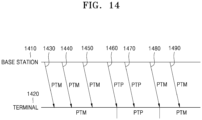
- FIG. 14 is a diagram showing an MBS split bearer and a path switch operation, according to an embodiment of the disclosure.
- the embodiment of FIG. 14 assumes that a terminal monitors both a PTM RLC and a PTP RLC configured for an MRB but activates only one RLC.
- the current embodiment shows a method of switching and applying an activated RLC entity (or an activated data path) when reception of a packet by the PTP RLC entity or the PTM RLC entity is detected.
- the embodiment of FIG. 14 assumes that a base station 1410 is transmitting data to a terminal 1420 by using the PTM RLC (1430, 1440, and 1450). In this case, the PTM RLC serves as an activated path of the terminal in the MRB. Then, when data to the PTP RLC is detected (1460), the terminal switches the activated RLC entity to the PTP RLC.
- the RLC entity may be initialized. That is, state variables of the RLC may be initialized and an RLC reception buffer may be emptied. In another embodiment, the RLC entity may be reestablished. In addition, the activated path may be signaled to a PDCP entity in a higher layer.
- FIG. 15 is a diagram showing an operation of receiving the first packet after a path of an MBS split bearer is switched, according to an embodiment of the disclosure.
- a terminal may receive the first packet after a path of an MBS split bearer is switched from a PTM RLC to a PTP RLC or vice versa as instructed according to the method of FIG. 13 or 14 or another method (or after an RLC entity is initially configured) (1510).
- the RLC entity may be reestablished (1520).
- the operation of reestablishing the RLC entity may include an operation of initializing state variables of the RLC and emptying an RLC reception buffer.
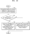
- FIG. 16 is a diagram showing an operation of receiving the first packet after a path of an MBS split bearer is switched, according to an embodiment of the disclosure.
- a terminal may receive the first packet after a path of an MBS split bearer is switched from a PTM RLC to a PTP RLC or vice versa as instructed according to the method of FIG. 13 or 14 or another method (or after an RLC entity is initially configured) (1610).
- state variables of the RLC entity may be initialized and an RLC reception buffer may be emptied.
- the terminal may determine whether the switched RLC entity (or the initially configured RLC entity) is an RLC UM entity or an RLC AM entity (1620).
- the terminal may set RX_Next_Reassembly and RX_Next_Highest among state variables of the RLC entity to a sequence number (SN) value of the first received packet having a SN (1630). Otherwise, when the RLC entity is an RLC AM entity, the terminal may set RX_Next and RX_Next_Highest among state variables of the RLC entity to a SN value of the first received packet having a SN (1640). Subsequent operations may follow pre-defined RLC reception operations.
- FIG. 17 is a diagram showing an operation of receiving the first packet after a path of an MBS split bearer is switched, according to an embodiment of the disclosure.
- a terminal may receive the first packet after a path of an MBS split bearer is switched from a PTM RLC to a PTP RLC or vice versa as instructed according to the method of FIG. 13 or 14 or another method (or after an RLC entity is initially configured) (1710).
- state variables of the RLC entity may be initialized and an RLC reception buffer may be emptied.
- the terminal may determine whether the switched RLC entity (or the initially configured RLC entity) is an RLC UM entity or an RLC AM entity (1720).
- SI field indicates segmentation of the packet, and the first bit of the SI field indicates whether a front part of the received service data unit (SDU) is segmented, and has a value of 1 when segmented.
- the second bit of the SI field indicates whether a rear part of the received SDU is segmented, and has a value of 1 when segmented.
- the SI field has a value of 00, it indicates that the RLC SDU is a complete unsegmented RLC SDU. Subsequent operations may follow pre-defined RLC reception operations.
- FIG. 18 is a diagram showing an operation of switching a path of an MBS split bearer, according to an embodiment of the disclosure.
- an existing RLC bearer may have data receivable using an existing RLC based on hybrid automatic repeat request (HARQ) retransmission or the like.
- HARQ hybrid automatic repeat request
- the switching of the RLC path may be delayed by a preset certain time (1820). A length of the delay time may be set using an RRC reconfiguration message transmitted from a base station.
- additional path switching may not be performed during the certain time to prevent unnecessary path switching by retransmitted packets.
- the current embodiment shows a method of switching to the PTP RLC after the delay time without switching to the PTM RLC even when data is received by the PTM RLC during the delay time.
- FIG. 19 is a diagram showing operation of an MRB for handover, according to an embodiment of the disclosure.
- the terminal may perform a handover procedure with respect to the target base station so as to receive data from the target base station.
- the same packets e.g., PDCP PDUs or PDCP SDUs
- packets allocated with SNs of 0, 1, 2, 3, and 4 may be allocated and used with SNs of 7, 8, 9, 10, and 11 in the target base station. In this case, the terminal needs to change the used SNs for handover.
- FIG. 19 packets allocated with SNs of 0, 1, 2, 3, and 4 may be allocated and used with SNs of 7, 8, 9, 10, and 11 in the target base station. In this case, the terminal needs to change the used SNs for handover.
- the serving base station and the target base station have a SN difference of 7 for PDCP packets of a specific MRB. Therefore, the serving base station may transmit an RRC reconfiguration message for handover to signal a difference of 7 in PDCP SNs from the target base station, and the terminal may change the PDCP SNs by using the difference after handover and continuously use the MRB for the same services in the target base station. The terminal may also compensate PDCP state variables by the PDCP SN difference to perform PDCP reception operation.
- COUNT values used in the PDCP status report message may be COUNT values to be converted and derived to SNs used in the target base station.
- FIG. 20 is a diagram showing changing of a bearer type including an MBS split bearer, according to an embodiment of the disclosure.
- MBS because a plurality of terminals receive data, transmission to one specific terminal may not be ensured.
- MBS services require high stability, broadcast or multicast transmission may not easily satisfy the requirement. For this reason, some packets of MBS data need to be transmitted in a unicast manner.
- an MRB using both PTM and PTP transmissions instead of using specific PTM or PTP transmission only may be defined. Because this MRB processes the same MBS services, only one SOAP layer and only one PDCP layer may be connected to a higher layer, and an RLC layer may include two or more RLC entities to use any RLC for PTM transmission (RLC-PTM or PTM RLC) and another RLC for PTP transmission (RLC-PTP or PTP RLC).
- Each RLC entity may correspond to a logic channel and the PTM RLC may be transmitted using a radio resource allocated with a G-RNTI whereas the PTP RLC may be transmitted using a radio resource allocated with a C-RNTI.
- Such radio bearer having both the PTP RLC and the PTM RLC may be referred to as an MBS split radio bearer (2010).
- a base station may arbitrarily determine an RLC entity of the MBS split radio bearer to be used for data transmission.
- the base station may switch a data transmission path.
- a PDCP entity of a terminal may receive packets in order without duplicates by using reordering and duplicate detection technologies.
- the MBS split radio bearer shown in operation 2010 assumes that data is always received by a PTM RLC and a PTP RLC of the terminal.
- the MRB does not necessarily have the PTP RLC. That is, when the base station has no problem with multicast or broadcast transmission using the PTM RLC, the PTP RLC is not additionally required.
- Such radio bearer having one PTM RLC may be referred to as a PTM MRB (2020).
- a radio bearer not having the PTM RLC but having only the PTP RLC to which a resource is allocated with a C-RNTI may also exist.
- Such radio bearer may be referred to as a DRB due to the same structure as an existing DRB, and also referred to as a PTP MRB with respect to a radio bearer for transmitting MBS data (2030).
- a bearer type may be changed between the MBS split radio bearer, the PTM MRB, and the PTP MRB.
- the terminal may transmit a PDCP status report message to the base station to request retransmission.
- the MRB e.g., the MBS split radio bearer, the PTM MRB, or the PTP MRB
- information indicating whether to maintain the PDCP SNs may be additionally signaled to the terminal.
- the base station may signal a PDCP SN (or COUNT) difference to the terminal.
- the PDCP status report message may be transmitted only when the PTP RLC is an RLC AM and not transmitted when the PTP RLC is an RLC UM. In some embodiments, when at least one of RLC release, MAC reset, or RLC reestablishment is performed to change the bearer type, the PDCP status report message may be transmitted to the base station.
- a machine-readable storage medium may be provided in the form of a non-transitory storage medium.
- the storage medium is 'non-transitory', it means that the storage medium is tangible and does not include signals (e.g., electromagnetic waves), and it does not limit that data is semi-permanently or temporarily stored in the storage medium.
- the 'non-transitory storage medium' may include a buffer that stores data temporarily.
- the method according to various embodiments of the disclosure may be included and provided in a computer program product.
- the computer program product may be traded as a commercial product between a seller and a buyer.
- the computer program product may be distributed in the form of a machine-readable storage medium (e.g., a compact disc read only memory (CD-ROM)), or be electronically distributed (e.g., downloaded or uploaded) via an application store (e.g., Play Store TM ) or directly between two user devices (e.g., smartphones).
- a machine-readable storage medium e.g., a compact disc read only memory (CD-ROM)
- an application store e.g., Play Store TM
- directly between two user devices e.g., smartphones.
- At least a part of the computer program product may be temporarily generated or be at least temporarily stored in a machine-readable storage medium, e.g., a memory of a server of a manufacturer, a server of an application store, or a relay server.
- a machine-readable storage medium e.g., a memory of a server of a manufacturer, a server of an application store, or a relay server.
Landscapes
- Engineering & Computer Science (AREA)
- Signal Processing (AREA)
- Computer Networks & Wireless Communication (AREA)
- Multimedia (AREA)
- Mobile Radio Communication Systems (AREA)
Applications Claiming Priority (3)
| Application Number | Priority Date | Filing Date | Title |
|---|---|---|---|
| KR20200056164 | 2020-05-11 | ||
| KR1020200137846A KR20210137880A (ko) | 2020-05-11 | 2020-10-22 | 무선 통신 시스템에서 mbs 서비스 연속성을 위한 bwp 설정 방법 및 장치 |
| PCT/KR2021/005817 WO2021230595A1 (fr) | 2020-05-11 | 2021-05-10 | Procédé et dispositif permettant de configurer une bwp pour une continuité de service de mbs dans un système de communication sans fil |
Publications (2)
| Publication Number | Publication Date |
|---|---|
| EP4142399A1 true EP4142399A1 (fr) | 2023-03-01 |
| EP4142399A4 EP4142399A4 (fr) | 2023-10-11 |
Family
ID=78524481
Family Applications (1)
| Application Number | Title | Priority Date | Filing Date |
|---|---|---|---|
| EP21804335.4A Pending EP4142399A4 (fr) | 2020-05-11 | 2021-05-10 | Procédé et dispositif permettant de configurer une bwp pour une continuité de service de mbs dans un système de communication sans fil |
Country Status (3)
| Country | Link |
|---|---|
| US (1) | US12452886B2 (fr) |
| EP (1) | EP4142399A4 (fr) |
| WO (1) | WO2021230595A1 (fr) |
Cited By (2)
| Publication number | Priority date | Publication date | Assignee | Title |
|---|---|---|---|---|
| WO2022077442A1 (fr) | 2020-10-16 | 2022-04-21 | Lenovo (Beijing) Limited | Procédé et appareil pour des services multicast et broadcast |
| EP4537555A4 (fr) * | 2023-02-16 | 2025-06-25 | ZTE Corporation | Service de multidiffusion et de diffusion dans divers états de commande de ressources radio |
Families Citing this family (11)
| Publication number | Priority date | Publication date | Assignee | Title |
|---|---|---|---|---|
| CN115804156B (zh) * | 2020-06-26 | 2025-07-25 | 高通股份有限公司 | 用于配置对半双工ue的补充下行链路支持的技术 |
| CN118843120A (zh) * | 2020-09-07 | 2024-10-25 | 中兴通讯股份有限公司 | 资源确定方法、通信节点及存储介质 |
| WO2022151046A1 (fr) * | 2021-01-13 | 2022-07-21 | Apple Inc. | Attribution de ressources de fréquence pour de nouveaux services de multidiffusion ou de diffusion radio |
| WO2022205381A1 (fr) * | 2021-04-01 | 2022-10-06 | 北京小米移动软件有限公司 | Procédé et appareil de transmission de service de diffusion ou de multidiffusion et support de stockage |
| US20240114577A1 (en) * | 2021-04-30 | 2024-04-04 | Qualcomm Incorporated | Techniques for radio resource control reconfiguration alignment |
| CN117730494A (zh) * | 2021-08-06 | 2024-03-19 | Lg 电子株式会社 | 无线通信系统中发送和接收pdsch的方法和设备 |
| CN118104343A (zh) * | 2021-12-23 | 2024-05-28 | Oppo广东移动通信有限公司 | 信息发送方法、信息接收方法、终端设备和网络设备 |
| EP4451792A4 (fr) * | 2022-01-18 | 2025-04-09 | Kyocera Corporation | Procédé de communication et équipement utilisateur |
| US20250089116A1 (en) * | 2022-01-29 | 2025-03-13 | Samsung Electronics Co., Ltd. | Method, base station, electronic apparatus and storage medium for supporting multicast transmission |
| US20240056775A1 (en) * | 2022-08-10 | 2024-02-15 | FG Innovation Company Limited | Method and device for multicast/broadcast service-related operations |
| US20250056577A1 (en) * | 2023-08-11 | 2025-02-13 | Qualcomm Incorporated | Physical downlink control channel monitoring for multicast broadcast service |
Family Cites Families (13)
| Publication number | Priority date | Publication date | Assignee | Title |
|---|---|---|---|---|
| EP3017616B1 (fr) * | 2013-07-01 | 2018-12-05 | NEC Corporation | Procédé de fourniture de continuité de service de diffusion groupée/générale à des terminaux mobiles |
| US10070272B2 (en) | 2015-05-15 | 2018-09-04 | Qualcomm Incorporated | Shared broadcast |
| CN108781346B (zh) | 2016-08-11 | 2020-12-18 | 华为技术有限公司 | 基于组播的无线通信方法、终端设备和基站 |
| KR102134504B1 (ko) * | 2017-01-05 | 2020-07-16 | 아서스테크 컴퓨터 인코포레이션 | 무선 통신 시스템에서 뉴머롤로지를 결정하는 방법 및 장치 |
| CN110603778B (zh) | 2017-05-05 | 2022-09-16 | 苹果公司 | 用于新无线电(nr)宽带用户设备(ue)的带宽部分配置和操作 |
| CN109309558B (zh) * | 2017-07-28 | 2021-10-08 | 株式会社Kt | 用于发送和接收上行链路信道的设备和方法 |
| EP3738350B1 (fr) * | 2018-01-11 | 2023-02-01 | Telefonaktiebolaget Lm Ericsson (Publ) | Procédés et appareil de mise à jour d'informations de système |
| CN110087311A (zh) | 2018-01-26 | 2019-08-02 | 华为技术有限公司 | 通信方法和通信设备 |
| MX2022008390A (es) * | 2020-01-10 | 2022-08-08 | Fg innovation co ltd | Metodo y equipo de usuario para recepcion de datos de servicio de multidifusion/difusion. |
| US11671979B2 (en) * | 2020-02-10 | 2023-06-06 | Qualcomm Incorporated | Techniques for indicating downlink control information in multicast/broadcast wireless communications |
| CN113271553B (zh) * | 2020-02-14 | 2022-11-18 | 株式会社Kt | 用于处理组播/广播服务数据的方法及其设备 |
| KR20210120391A (ko) | 2020-03-26 | 2021-10-07 | 삼성전자주식회사 | Mbs 설정의 시작 시점을 위한 방법 및 장치 |
| CN113453337B (zh) * | 2020-03-27 | 2023-06-27 | 维沃移动通信有限公司 | 广播多播业务传输方法、广播多播业务传输指示方法及设备 |
-
2021
- 2021-05-10 EP EP21804335.4A patent/EP4142399A4/fr active Pending
- 2021-05-10 WO PCT/KR2021/005817 patent/WO2021230595A1/fr not_active Ceased
- 2021-05-10 US US17/923,518 patent/US12452886B2/en active Active
Cited By (4)
| Publication number | Priority date | Publication date | Assignee | Title |
|---|---|---|---|---|
| WO2022077442A1 (fr) | 2020-10-16 | 2022-04-21 | Lenovo (Beijing) Limited | Procédé et appareil pour des services multicast et broadcast |
| EP4229906A4 (fr) * | 2020-10-16 | 2024-07-17 | Lenovo (Beijing) Limited | Procédé et appareil pour des services multicast et broadcast |
| US12520380B2 (en) | 2020-10-16 | 2026-01-06 | Lenovo (Beijing) Limited | Method and apparatus for multicast and broadcast services |
| EP4537555A4 (fr) * | 2023-02-16 | 2025-06-25 | ZTE Corporation | Service de multidiffusion et de diffusion dans divers états de commande de ressources radio |
Also Published As
| Publication number | Publication date |
|---|---|
| US12452886B2 (en) | 2025-10-21 |
| WO2021230595A1 (fr) | 2021-11-18 |
| US20230189295A1 (en) | 2023-06-15 |
| EP4142399A4 (fr) | 2023-10-11 |
Similar Documents
| Publication | Publication Date | Title |
|---|---|---|
| US12452886B2 (en) | Method and device for configuring BWP for continuity of MBS service in wireless communication system | |
| US20230135437A1 (en) | Method and apparatus for supporting carrier aggregation in wireless communication system | |
| US11224050B2 (en) | Method and apparatus for allocating dynamic resources of integrated access and backhaul nodes in wireless communication system | |
| EP3840430B1 (fr) | Procédé et appareil d'émission ou de réception de données dans un système de communication sans fil | |
| US20230345509A1 (en) | Multicast/broadcast service alert | |
| US12120765B2 (en) | Method and device for supporting vehicle communication in wireless communication system | |
| US11632690B2 (en) | Method and apparatus for synchronizing packet duplication operation between base station nodes in mobile communication system | |
| EP4120736A1 (fr) | Procédé et dispositif de prise en charge d'une continuité d'un service de diffusion dans un système de communication sans fil | |
| US12355574B2 (en) | Method and apparatus for applying HARQ to multicast broadcast service in wireless communication system | |
| EP4135454B1 (fr) | Procédé et dispositif de commutation de bwp pour la réception de mbs dans un système de communication mobile | |
| EP4145952A1 (fr) | Structure porteuse pour supporter une multidiffusion dans un système de communication mobile de prochaine génération, et procédé et dispositif de support | |
| US12615690B2 (en) | Method and device for security MBS communication in wireless communication system | |
| US12058558B2 (en) | Method and apparatus for synchronizing packet duplication operation between base station nodes in mobile communication system | |
| CN113273283B (zh) | 用于控制下一代移动通信系统中的辅小区的休眠状态的方法和装置 | |
| KR20220052750A (ko) | 무선 통신 시스템에서 mbs 통신을 위한 방법 및 장치 | |
| KR20230128467A (ko) | L2 릴레이 이동성을 위한 순방향 핸드오버 절차들 | |
| KR20210137880A (ko) | 무선 통신 시스템에서 mbs 서비스 연속성을 위한 bwp 설정 방법 및 장치 | |
| US12445937B2 (en) | Method for terminal to control connection to base station on basis of load of base station in wireless communication system | |
| KR102874326B1 (ko) | 무선 통신 시스템에서 plmn을 획득하는 방법 및 장치 | |
| KR102954148B1 (ko) | 이동 통신 시스템에서 mbs 수신을 위한 bwp 전환 방법 및 장치 | |
| KR102917607B1 (ko) | 무선 통신 시스템에서 단말의 상태 천이 시 메시지 전송 방법 및 장치 |
Legal Events
| Date | Code | Title | Description |
|---|---|---|---|
| STAA | Information on the status of an ep patent application or granted ep patent |
Free format text: STATUS: THE INTERNATIONAL PUBLICATION HAS BEEN MADE |
|
| PUAI | Public reference made under article 153(3) epc to a published international application that has entered the european phase |
Free format text: ORIGINAL CODE: 0009012 |
|
| STAA | Information on the status of an ep patent application or granted ep patent |
Free format text: STATUS: REQUEST FOR EXAMINATION WAS MADE |
|
| 17P | Request for examination filed |
Effective date: 20221124 |
|
| AK | Designated contracting states |
Kind code of ref document: A1 Designated state(s): AL AT BE BG CH CY CZ DE DK EE ES FI FR GB GR HR HU IE IS IT LI LT LU LV MC MK MT NL NO PL PT RO RS SE SI SK SM TR |
|
| DAV | Request for validation of the european patent (deleted) | ||
| DAX | Request for extension of the european patent (deleted) | ||
| A4 | Supplementary search report drawn up and despatched |
Effective date: 20230912 |
|
| RIC1 | Information provided on ipc code assigned before grant |
Ipc: H04W 76/40 20180101ALI20230906BHEP Ipc: H04W 72/30 20230101ALI20230906BHEP Ipc: H04W 72/0453 20230101ALI20230906BHEP Ipc: H04W 4/06 20090101ALI20230906BHEP Ipc: H04W 76/27 20180101ALI20230906BHEP Ipc: H04W 72/00 20230101ALI20230906BHEP Ipc: H04W 72/04 20230101AFI20230906BHEP |
|
| STAA | Information on the status of an ep patent application or granted ep patent |
Free format text: STATUS: EXAMINATION IS IN PROGRESS |