EP4142402A1 - Communication control method and user equipment - Google Patents
Communication control method and user equipment Download PDFInfo
- Publication number
- EP4142402A1 EP4142402A1 EP21812161.4A EP21812161A EP4142402A1 EP 4142402 A1 EP4142402 A1 EP 4142402A1 EP 21812161 A EP21812161 A EP 21812161A EP 4142402 A1 EP4142402 A1 EP 4142402A1
- Authority
- EP
- European Patent Office
- Prior art keywords
- ptp
- radio bearer
- base station
- ptm
- user equipment
- Prior art date
- Legal status (The legal status is an assumption and is not a legal conclusion. Google has not performed a legal analysis and makes no representation as to the accuracy of the status listed.)
- Granted
Links
Images


Classifications
-
- H—ELECTRICITY
- H04—ELECTRIC COMMUNICATION TECHNIQUE
- H04W—WIRELESS COMMUNICATION NETWORKS
- H04W76/00—Connection management
- H04W76/40—Connection management for selective distribution or broadcast
-
- H—ELECTRICITY
- H04—ELECTRIC COMMUNICATION TECHNIQUE
- H04L—TRANSMISSION OF DIGITAL INFORMATION, e.g. TELEGRAPHIC COMMUNICATION
- H04L12/00—Data switching networks
- H04L12/02—Details
- H04L12/16—Arrangements for providing special services to substations
- H04L12/18—Arrangements for providing special services to substations for broadcast or conference, e.g. multicast
- H04L12/189—Arrangements for providing special services to substations for broadcast or conference, e.g. multicast in combination with wireless systems
-
- H—ELECTRICITY
- H04—ELECTRIC COMMUNICATION TECHNIQUE
- H04W—WIRELESS COMMUNICATION NETWORKS
- H04W36/00—Hand-off or reselection arrangements
- H04W36/0005—Control or signalling for completing the hand-off
- H04W36/0007—Control or signalling for completing the hand-off for multicast or broadcast services, e.g. MBMS
-
- H—ELECTRICITY
- H04—ELECTRIC COMMUNICATION TECHNIQUE
- H04W—WIRELESS COMMUNICATION NETWORKS
- H04W4/00—Services specially adapted for wireless communication networks; Facilities therefor
- H04W4/06—Selective distribution of broadcast services, e.g. multimedia broadcast multicast service [MBMS]; Services to user groups; One-way selective calling services
-
- H—ELECTRICITY
- H04—ELECTRIC COMMUNICATION TECHNIQUE
- H04W—WIRELESS COMMUNICATION NETWORKS
- H04W72/00—Local resource management
- H04W72/30—Resource management for broadcast services
Definitions
- the present invention relates to a communication control method and a user equipment in mobile communication systems.
- the 3GPP (3rd Generation Partnership Project), which is a standardization project for mobile communication systems, has been conducting standardization of NR (New Radio) positioned as the 5th generation (5G) radio access technology.
- NR New Radio
- the current NR specification has not defined a mechanism for an MBS (Multicast and Broadcast Services) service.
- MBS Multicast and Broadcast Services
- the 3GPP has started a discussion to introduce the MBS service (NPL 1).
- NPL 1 3GPP Contribution "RP-193248"
- a communication control method includes receiving, by a user equipment, a data packet belonging to an MBS (Multicast and Broadcast Services) service via a PTM (Point-to-Multipoint) radio bearer, receiving, by the user equipment from a base station, configuration information for configuring association between the PTM radio bearer and a PTP (Point-to-Point) data path for receiving the data packet belonging to the MBS service, and associating, by the user equipment, the PTP data path with the PTM radio bearer based on the configuration information.
- MBS Multicast and Broadcast Services
- PTM Point-to-Multipoint
- a user equipment in a second aspect, includes a receiver configured to receive a data packet belonging to an MBS (Multicast and Broadcast Services) service via a PTM (Point-to-Multipoint) radio bearer, and a controller.
- the receiver receives, from a base station, configuration information for configuring association between the PTM radio bearer and a PTP (Point-to-Point) data path for receiving the data packet belonging to the MBS service.
- the controller associates the PTP data path with the PTM radio bearer based on the configuration information.
- a delivery of an MBS service to a user equipment may be desirably switched in an appropriate manner between a PTM (Point-to-Multipoint) transmission and a PTP (Point-to-Point) transmission.
- PTM Point-to-Multipoint
- PTP Point-to-Point
- the object of the present disclosure is to control, in an appropriate manner, the switching of the delivery of the MBS service between the PTM transmission and the PTP transmission.
- the mobile communication system according to the embodiment is a 5G system of the 3GPP
- LTE may be at least partially applied to the mobile communication system.
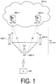
- FIG. 1 is a diagram illustrating a configuration of the mobile communication system according to an embodiment.
- the mobile communication system includes a user equipment (UE) 100, a 5G radio access network (NG-RAN (next generation radio access network)) 10, and a 5G core network (5GC) 20.
- UE user equipment
- NG-RAN next generation radio access network
- 5GC 5G core network
- the LTE 100 is a mobile apparatus.
- the UE 100 may be any apparatus as long as the UE 100 is used by a user.
- Examples of the UE 100 include a mobile phone terminal (including a smartphone), a tablet terminal, a notebook PC, a communication module (including a communication card or a chipset), a sensor or an apparatus provided on a sensor, a vehicle or an apparatus provided on a vehicle (Vehicle LTE), and/or a flying object or an apparatus provided on a flying object (Aerial UE).
- the NG-RAN 10 includes base stations (referred to as "gNBs" in the 5G system) 200.
- the gNBs 200 may also be referred to as NG-RAN nodes.
- the gNBs 200 are interconnected via an Xn interface which is an inter-base station interface.
- Each gNB 200 manages one or a plurality of cells.
- the gNB 200 performs wireless communication with the UE 100 that has established a connection to a cell of the gNB 200.
- the gNB 200 has a radio resource management (RRM) function, a function of routing user data (hereinafter simply referred to as "data"), and/or a measurement control function for mobility control and scheduling, or the like.
- RRM radio resource management
- a “cell” is used as a term to indicate a minimum unit of a wireless communication area.
- a “cell” is also used as a term to indicate a function or a resource for performing wireless communication with the LTE 100.
- One cell belongs to one carrier
- the gNB may be connected to an Evolved Packet Core (EPC) which is a core network of LTE, or a base station of LTE may be connected to the 5GC.
- EPC Evolved Packet Core
- the base station of LTE and the gNB may be connected via the inter-base station interface.
- the 5GC 20 includes an Access and Mobility Management Function (AMF) and a User Plane Function (UPF) 300.
- the AMF performs various types of mobility controls and the like for the UE 100.
- the AMF manages information of an area in which the UE 100 exists by communicating with the UE 100 by using Non-Access Stratum (NAS) signaling.
- NAS Non-Access Stratum
- the UPF controls data transfer.
- the AMF and the UPF are connected to the gNB 200 via an NG interface which is an interface between the base station and the core network.
- FIG. 2 is a diagram illustrating a configuration of the UE 100 (user equipment).
- the UE 100 includes a receiver 110, a transmitter 120, and a controller 130.
- the receiver 110 performs various types of receptions under control of the controller 130.
- the receiver 110 includes an antenna and a reception device.
- the reception device converts a radio signal received through the antenna into a baseband signal (a reception signal) and outputs the resulting signal to the controller 130.
- the transmitter 120 performs various types of transmissions under control of the controller 130.
- the transmitter 120 includes an antenna and a transmission device.
- the transmission device converts a baseband signal output by the controller 130 (a transmission signal) into a radio signal and transmits the resulting signal through the antenna.
- the controller 130 performs various types of controls in the UE 100.
- the controller 130 includes at least one processor and at least one memory electrically connected to the processor.
- the memory stores programs to be executed by the processor and information to be used for processes by the processor.
- the processor may include a baseband processor and a Central Processing Unit (CPU).
- the baseband processor performs modulation and demodulation, coding and decoding, and the like of a baseband signal.
- the CPU executes the programs stored in the memory to perform various types of processes.
- FIG. 3 is a diagram illustrating a configuration of the gNB 200 (a base station).
- the gNB 200 includes a transmitter 210, a receiver 220, a controller 230, and a backhaul communicator 240.
- the transmitter 210 performs various types of transmissions under control of the controller 230.
- the transmitter 210 includes an antenna and a transmission device.
- the transmission device converts a baseband signal output by the controller 230 (a transmission signal) into a radio signal and transmits the resulting signal through the antenna.
- the receiver 220 performs various types of receptions under control of the controller 230.
- the receiver 220 includes an antenna and a reception device.
- the reception device converts a radio signal received through the antenna into a baseband signal (a reception signal) and outputs the resulting signal to the controller 230.
- the controller 230 performs various types of controls in the gNB 200.
- the controller 230 includes at least one processor and at least one memory electrically connected to the processor.
- the memory stores programs to be executed by the processor and information to be used for processes by the processor.
- the processor may include a baseband processor and a CPU.
- the baseband processor performs modulation and demodulation, coding and decoding, and the like of a baseband signal.
- the CPU executes the programs stored in the memory to perform various types of processes.
- the backhaul communicator 240 is connected to a neighboring base station via the inter-base station interface.
- the backhaul communicator 240 is connected to the AMF/LTPF 300 via the interface between a base station and the core network.
- the gNB may include a Central Unit (CU) and a Distributed Unit (DU) (i.e., functions are divided), and the two units may be connected via an F1 interface.
- CU Central Unit
- DU Distributed Unit
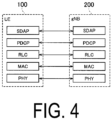
- FIG. 4 is a diagram illustrating a configuration of a protocol stack of a radio interface of a user plane handling data.
- the radio interface protocol of the user plane includes a physical (PHY) layer, a Medium Access Control (MAC) layer, a Radio Link Control (RLC) layer, a Packet Data Convergence Protocol (PDCP) layer, and a Service Data Adaptation Protocol (SDAP) layer.
- PHY physical
- MAC Medium Access Control
- RLC Radio Link Control
- PDCP Packet Data Convergence Protocol
- SDAP Service Data Adaptation Protocol
- the PHY layer provides a transport channel to the MAC layer.
- the PHY layer performs coding and decoding, modulation and demodulation, antenna mapping and demapping, and resource mapping and demapping.
- the MAC layer performs priority control of data, a retransmission process through a hybrid ARQ (HARQ) (HARQ process), a random access procedure, and the like.
- Data and control information are transmitted between the MAC layer of the UE 100 and the MAC layer of the gNB 200 via a transport channel.
- the MAC layer of the gNB 200 includes a scheduler. The scheduler determines transport formats (transport block sizes, modulation and coding schemes (MCSs)) in the uplink and the downlink and resource blocks to be allocated to the UE 100.
- MCSs modulation and coding schemes
- the MAC layer provides a logical channel to the RLC layer. A MAC entity resides in the MAC layer.
- the RLC layer transmits data to the RLC layer on the reception side by using functions of the MAC layer and the PHY layer.
- the RLC layer performs a retransmission process through an ARQ (ARQ process).
- ARQ process ARQ process
- the RLC layer provides an RLC channel to the PDCP layer.
- An RLC entity resides in the RLC layer.
- the PDCP layer performs data transfer, PDCP SN maintenance, header compression and decompression, and encryption and decryption.
- the PDCP layer provides a radio bearer to the SDAP layer.
- a PDCP entity resides in the PDCP layer.
- One PDCP entity carries data of one radio bearer.
- the SDAP layer performs mapping between QoS flows and radio bearers.
- the QoS flow is a unit of performing QoS control by the core network. Note that, when the RAN is connected to the EPC, the SDAP layer need not be provided. An SDAP entity resides in the SDAP layer.
- FIG. 5 is a diagram illustrating a configuration of a protocol stack of a radio interface in a control plane handling signaling (control signals).
- the protocol stack of the radio interface in the control plane includes a Radio Resource Control (RRC) layer and a Non-Access Stratum (NAS) layer instead of the SDAP layer illustrated in FIG. 4 .
- RRC Radio Resource Control
- NAS Non-Access Stratum
- RRC signaling for various configurations is transmitted between the RRC layer of the LTE 100 and the RRC layer of the gNB 200.
- the RRC layer controls a logical channel, a transport channel, and a physical channel according to establishment, reestablishment, and release of the radio bearer.
- RRC connection When a connection between the RRC of the UE 100 and the RRC of the gNB 200 (RRC connection) exists, the UE 100 is in an RRC connected state.
- RRC connection When a connection between the RRC of the UE 100 and the RRC of the gNB 200 (RRC connection) does not exist, the UE 100 is in an RRC idle state.
- the RRC connection is suspended, the UE 100 is in an RRC inactive state.
- the NAS layer higher than the RRC layer performs session management, mobility management, and the like.
- NAS signaling is transmitted between the NAS layer of the UE 100 and the NAS layer of the AMF 300.
- the LTE 100 has an application layer and the like other than the protocol of the radio interface.
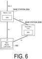
- FIG. 6 is a diagram illustrating an example of DC.
- the LTE 100 including a plurality of transceivers is configured to utilize resources (time resources and frequency resources) provided by two different nodes (two different base stations).
- One base station provides NR access and the other base station provides E-UTRA (LTE) or NR access.
- a base station 200A may be an eNB or a gNB
- a base station 200B may be an eNB or a gNB.
- the one base station 200A functions as a master node, and the other base station 200B functions as a secondary node.
- the master node is a radio access node that provides control plane connection to the core network.
- the master node may be referred to as a master base station.
- the secondary node is a radio access node that does not have control plane connection to the core network.
- the secondary node may be referred to as a secondary base station.
- the master node is connected to the secondary node via a network interface (inter-base station interface), and at least the master node is connected to the core network.
- FIG. 6 illustrates an example in which the inter-base station interface is an Xn interface; however, the inter-base station interface may be an X2 interface.
- a group of serving cells that are cells of the master node and are configured for the LTE 100 is referred to as a master cell group (MCG).
- MCG master cell group
- SCG secondary cell group
- the UE 100 includes a MAC entity corresponding to the MCG (MCG MAC) and a MAC entity corresponding to the SCG (SCG MAC).
- the UE 100 may receive the MBS service in an RRC connected state, or may receive the MBS service in the RRC idle state or the RRC inactive state.
- FIG. 7 is a diagram illustrating an example for receiving the MBS service.
- the UE 100 acquires MBS basic information from the 5GC 20 via the gNB 200.
- the MBS basic information may be referred to as a User Service Description (USD).
- the MBS basic information includes, for each MBS service, MBS identification information for identifying the MBS service and a frequency at which the MBS service is provided.
- the MBS identification information may be referred to as a Temporary Mobile Group Identity (TMGI).
- TMGI Temporary Mobile Group Identity
- step S2 the UE 100 receives an MBS SIB from the gNB 200.
- the MBS SIB includes information required for acquiring a PTM control channel for MBS (scheduling information).
- the UE 100 receives MBS control information from the gNB 200 via the PTM control channel for MBS, based on the MBS SIB.
- the MBS control information includes information required for configuring a PTM data channel for the MBS in the cell in which the MBS control information is transmitted.
- the PTM data channel is a PTM logical channel for data transmission.
- the PTM logical channel may be a multicast logical channel, or may be a broadcast logical channel.
- step S4 the UE 100 establishes a PTM radio bearer with the gNB 200 based on the MBS control information, and receives, via the PTM radio bearer, a data packet belonging to the MBS service in which the UE 100 has interest (MBS data packet).
- MBS data packet a data packet belonging to the MBS service in which the UE 100 has interest
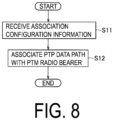
- FIG. 8 is a diagram illustrating a sequence of a basic operation according to an embodiment.
- the UE 100 receives, from the gNB 200, association configuration information for configuring association of the PTM radio bearer with a PTP data path to receive the data belonging to the MBS service (MBS data).
- the PTP data path is a PTP radio bearer or a PTP logical channel.
- the PTP data path may be an IP flow.
- the IP flow is a stream of a series of packets from a particular IP address to a particular IP address.
- the PTP radio bearer may be a unicast radio bearer.
- the PTP logical channel may be a unicast logical channel.
- step S12 the UE 100 associates the PTP data path with the PTM radio bearer based on the association configuration information. This allows the delivery of the MBS service to the UE 100 to be switched between the PTM and the PTP.
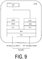
- FIG. 9 is a diagram illustrating association between the PTP radio bearer and the PTM radio bearer.
- the UE 100 associates the PTP radio bearer (RB #2) with the PTM radio bearer (RB #1) based on the association configuration information.
- association configuration information includes information for configuring the association between the PTP radio bearer and the PTM radio bearer (hereinafter, referred to as "PTP radio bearer configuration information").
- the PTP radio bearer configuration information includes a bearer identifier of the PTP radio bearer (a bearer identifier of RB #2) and PDCP configuration information for configuring a PDCP entity of the PTP radio bearer.
- the PTP radio bearer configuration information may further include a bearer identifier of the PTM radio bearer to be associated with the PTP radio bearer.
- the PTP radio bearer to be associated with the PTM radio bearer may be a radio bearer already established in the UE 100, or may be a radio bearer that the UE 100 newly establishes.
- the UE 100 determines whether the bearer identifier of the PTP radio bearer included in the PTP radio bearer configuration information is already stored in the UE 100.
- the bearer identifier is already stored in the UE 100 (i.e., when the UE 100 already establishes the PTP radio bearer identifying the bearer identifier)
- the UE 100 reconfigures the PDCP entity of the PTP radio bearer identified by the bearer identifier based on the PDCP configuration information.
- the bearer identifier is not stored in the UE 100, the UE 100 newly establishes a PDCP entity based on the PDCP configuration information, and newly establishes a PTP radio bearer corresponding to the PDCP entity.
- the PTP radio bearer configuration information may include SDAP configuration information configuring the SDAP entity corresponding to the PTM radio bearer.
- the UE 100 configures the SDAP entity corresponding to the PTM radio bearer based on the SDAP configuration information.
- the PTP radio bearer configuration information may include an identifier of the MBS service to which the data packet transmitted on the PTP radio bearer belongs.
- the UE 100 includes a higher layer entity (MBS entity) residing in a higher layer than the PDCP layer, the higher layer entity managing the MBS service.
- MBS entity a higher layer entity
- the PDCP entity or the SDAP entity passes the data packet received via the PTP radio bearer to the MBS entity.
- the MBS entity may be included in the SDAP entity (i.e., the SDAP entity manages the MBS service).
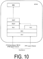
- FIG. 10 is a diagram illustrating association between the PTP logical channel and the PTM radio bearer.
- the UE 100 associates the PTP logical channel with the PTM radio bearer (RB #1) based on the association configuration information.
- association configuration information includes information for configuring the association between the PTP logical channel and the PTM radio bearer (hereinafter, referred to as "PTP logical channel configuration information").
- the PTP logical channel configuration information includes the bearer identifier of the PTM radio bearer and a channel identifier of the PTP logical channel to be associated with the PTM radio bearer.
- the UE 100 determines whether the channel identifier included in the PTP radio bearer configuration information is already stored in the UE 100. When the channel identifier is already stored in the LTE 100, the LTE 100 reconfigures the RLC entity corresponding to the PTP logical channel identified by the channel identifier. When the channel identifier is not stored in the UE 100, the UE 100 newly establishes an RLC entity, and newly establishes a PTP logical channel corresponding to the RLC entity.
- the UE 100 associates the PTP logical channel identified by the channel identifier with the PDCP entity of the PTM radio bearer.
- the PDCP entity of the PTM radio bearer is associated with one PTM logical channel and one PTP logical channel.
- the RLC entity corresponding to the PTP logical channel delivers the data packet received via the PTP logical channel to the PDCP entity of the PTM radio bearer.
- the UE 100 may enable or disable the PTP data path described above (the PTP data path for the UE 100 to receive the data belonging to the MBS service) in response to an indication from the gNB 200. This allows the delivery of the MBS service to the UE 100 to be dynamically switched between the PTM and the PTP. Note that the UE 100 may enable or disable the PTM data path (the PTM radio bearer or the PTM logical channel) in response to an indication from the gNB 200.
- the PTM data path the PTM radio bearer or the PTM logical channel
- the association configuration information described above may include information configuring an initial state (enabled state or disabled state) of the PTP data path configured with the association. Enabling the PTP data path includes starting a reception via the PTP data path. Disabling the PTP data path includes stopping a reception via the PTP data path. For example, once the LTE 100 receives the association configuration information including the information configuring the initial state of the PTP data path as the disabled state, the UE 100 associates the PTP data path with the PTM radio bearer and disables the PTP data path. After that, the UE 100 enables the PTP data path in response to an indication from the gNB 200, and starts receiving the MBS data via the PTM data path. Note that the association configuration information may include information configuring an initial state (enabled state or disabled state) of the PTM data path configured with the association.
- the UE 100 when associating the PTP radio bearer with the PTM radio bearer, may stop the reception via the PTM radio bearer after the PTP radio bearer is enabled.
- the LTE 100 when associating the PTP logical channel with the PTM radio bearer, may stop the reception via the PTM logical channel associated with the PTM radio bearer after the PTP logical channel is enabled.
- the indication of the enabling and/or the indication of the disabling described above are performed, for example, by a MAC CE (Control Element).
- the indication may include an identifier indicating a subject (the PTP data path and/or the PTM data path) to be enabled/disabled.
- the indication may include information indicating the enabling/disabling (for example, 1 bit), and the information may be associated with a subject (the PTP data path and/or the PTM data path) to be enabled/disabled by an array.
- the gNB 200 transmits the information indicating the association to another gNB 200 managing a target cell to which the UE 100 is to be handed over.
- the PTP data path in the association described above may be a data path that uses resources of the secondary node (the base station 200B) (hereinafter, referred to as a "SCG data path").
- the PTM radio bearer is established between the LTE 100 and the master node (the base station 200A).
- the PTP radio bearer is a radio bearer established between the UE 100 and the base station 200B.
- the PTP logical channel is a logical channel corresponding to the SCG MAC entity of the UE 100.
- the UE 100 receives the association configuration information from the base station 200A, and configures association.
- the base station 200A transmits information indicating the association configured by the association configuration information to the base station 200B.
- the operation pattern 1 is an example of transmitting, by the UE 100, a sequence number corresponding to the MBS data packet required to receive in the PTP transmission.
- FIG. 11 is a diagram illustrating an operation in the operation pattern 1.
- the UE 100 In an initial state of the operation pattern, the UE 100 is in a state of establishing the RRC connection with the gNB 200 (RRC connected state).
- step S101 the UE 100 receives the MBS service from the gNB 200 via the PTM radio bearer.
- the UE 100 receives the association configuration information from the gNB 200.
- the association configuration information includes the information configuring the initial state of the PTM data path as the disabled state.
- the association configuration information may be transmitted in an RRC message (e.g., RRCReconfiguration message).
- step S103 the UE 100 associates the PTP data path with the PTM radio bearer and disables the PTP data path.
- step S104 the LTE 100 measures a parameter indicating a communication quality between the LTE 100 and the gNB 200 (a communication quality on the PTM radio bearer) to determine whether the parameter meets a threshold condition.
- the parameter indicating the communication quality corresponds to at least one selected from the group consisting of a Reference Signal Received Power (RSRP), a Reference Signal Received Quality (RSRQ), a Reference Signal-Signal to Interference plus Noise power Ratio (RS-SINR), a throughput, an error rate, the number of data packets for reception failure, and a duration of the reception failure (e.g., the number of milliseconds, the number of subframes, or the number of SFNs).
- RSRP Reference Signal Received Power
- RSRQ Reference Signal Received Quality
- RS-SINR Reference Signal-Signal to Interference plus Noise power Ratio
- a throughput e.g., the number of milliseconds, the number of subframes, or the number of SFNs.
- the parameter indicating the communication quality meeting the threshold condition indicates that the communication quality is not good.
- meeting the threshold condition means that the parameter indicating the communication quality is equal to or less than a threshold.
- the parameter indicating the communication quality corresponds to at least one selected from the group consisting of the error rate, the number of data packets for the reception failure, and the duration of the reception failure
- meeting the threshold condition means that the parameter indicating the communication quality is less than a threshold.
- the threshold of the threshold condition is configured by the gNB 200 for the UE 100.
- step S104 When the parameter indicating the communication quality meets the threshold condition (step S104: YES), the UE 100 causes the process to proceed to step S105.
- step S105 the UE 100 transmits, to the gNB 200, information indicating the sequence number corresponding to the MBS data packet required to receive in the PTP transmission scheme (hereinafter, "SN information").
- the SN information may be transmitted in the RRC message.
- the sequence number is any one of a PDCP sequence number, an RLC sequence number, and a new sequence number for MBS.
- the new sequence number for MBS may be defined as a PDU (Packet Data Unit) header dedicated to the MBS in a SDAP header, for example.
- PDU Packet Data Unit
- the SN information may indicate one sequence number (e.g., SN #n) corresponding to the first MBS data packet which the UE 100 is required to receive in the PTP transmission scheme, or may indicate a range of the sequence numbers (e.g., SN #n to SN #n + m) corresponding to a plurality of MBS data packets which the UE 100 is required to receive in the PTP transmission scheme.
- sequence numbers e.g., SN #n
- the SN information may include identification information for identifying the MBS service to which the MBS data packet belongs.
- the SN information may include the bearer identifier of the PTM radio bearer.
- step S106 the gNB 200 transmits an indication of enabling the PTP data path to the UE 100.
- step S107 the UE 100 enables the PTP data path and starts receiving the MBS data packet via the PTP data path.
- the gNB 200 when receiving the SN information indicating one sequence number, transmits the MBS data packet corresponding to the sequence number and subsequent MBS data packets to the UE 100 via the PTP data path.
- the gNB 200 when receiving the SN information indicating the range of the sequence numbers, transmits a plurality of MBS data packets corresponding to the range of the sequence numbers to the UE 100 via the PTP data path.
- the gNB 200 when completing the transmission of the plurality of MBS data packets, may transmit an indication of disabling the PTP data path to the UE 100.
- the process in step S104 may be omitted.
- the LTE 100 transmits the SN information.
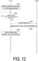
- FIG. 12 is a diagram illustrating an operation in the operation pattern 2.
- the state of the UE 100 corresponds to any one of the RRC connected state, the RRC idle state, and the RRC inactive state.
- step S201 the UE 100 receives the MBS service from the gNB 200 via the PTM radio bearer.
- step S202 is the same as, and/or similar to, the process in step S104.
- the UE 100 transmits the SN information to the gNB 200.
- the UE 100 may transition to the RRC connected state, and then transmit the SN information to the gNB 200.
- the LTE 100 may transmit the SN information while an RRC connection establishment procedure to transition from the RRC idle state to the RRC connected state is performed.
- the UE 100 includes and transmits the SN information in an RRCSetupRequest message.
- the UE 100 may transmit the SN information while an RRC connection resume procedure to transition from the RRC inactive state to the RRC connected state is performed.
- the UE 100 includes and transmits the SN information in an RRCResumeRequest message.
- step S204 the UE 100 receives the association configuration information from the gNB 200.
- the association configuration information includes information for configuring the initial state of the PTM data path to be the enabled state.
- the association configuration information may be transmitted in an RRCReconfiguration message.
- the gNB 200 in step S203 When the gNB 200 in step S203 receives the RRCSetupRequest message including the SN information, the gNB 200 in step S204 includes and transmits the association configuration information in the RRCSetup message.
- the RRCSetup message is a message for causing the UE 100 to transition from the RRC idle state to the RRC connected state. The UE 100 transitions to the RRC connected state in response to the reception of the RRCSetup message.
- the gNB 200 in step S203 When the gNB 200 in step S203 receives the RRCResumeRequest message including SN information, the gNB 200 in step S204 includes and transmits the association configuration information in the RRCResume message.
- the RRCResume message is a message for causing the LTE 100 to transition from the RRC inactive state to the RRC connected state. The UE 100 transitions to the RRC connected state in response to the reception of the RRCResume message.
- step S205 the UE 100 associates the PTP data path with the PTM radio bearer, and enables the PTP data path to start receiving the MBS data packet via the PTP data path.
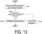
- FIG. 13 is a diagram illustrating an operation for the operation pattern 3.
- the state of the UE 100 corresponds to any one of the RRC connected state, the RRC idle state, and the RRC inactive state.
- step S301 the UE 100 receives the MBS service from the gNB 200 via the PTM radio bearer.
- step S302 is the same as, and/or similar to, the process in step S104.
- step S302: YES When the parameter indicating the communication quality meets the threshold condition (step S302: YES), the UE 100 causes the process to proceed to step S303.
- step S302: NO when the parameter indicating the communication quality does not meet the threshold condition (step S302: NO), the UE 100 causes the process to proceed to step S304.
- step S303 the UE 100 transmits the SN information to the gNB 200.
- the UE 100 applies the transmission of Negative Acknowledgement (NACK) feedback.
- the NACK feedback is feedback information for requesting retransmission of the MBS data packet via the PTM radio bearer.
- the NACK feedback may be information for requesting retransmission by a HARQ process (HARQ feedback), or may be information for requesting retransmission by an ARQ process (ARQ feedback).
- HARQ feedback HARQ feedback
- ARQ feedback ARQ feedback
- the UE 100 applying the transmission of the NACK feedback when failing to receive the MBS data packet transmitted via the PTM radio bearer, transmits the NACK feedback corresponding to the MBS data packet to the gNB 200.
- the gNB 200 when receiving the NACK feedback, retransmits the data packet corresponding to the NACK feedback on the PTM radio bearer (PTM logical channel).
- the UE 100 under the gNB 200 applies the transmission of the NACK feedback or switches to the PTP transmission depending on the communication quality. Accordingly, frequent PTM retransmissions due to all the UEs 100 under the gNB 200 applying the transmission of the NACK feedback can be avoided.
- the UE 100 associates one PTM logical channel with one PTP logical channel based on the association configuration information, but the embodiment is not limited thereto.
- the UE 100 when receiving the MBS service via one or more PTM logical channels, may receive, from the gNB 200, the association configuration information including information configuring associations between one or more PTP logical channels and one or more PTM logical channels to configure the associations.
- a program may be provided that causes a computer to execute each of processes performed by the UE 100 or the base stations 200 (the base station 200A, the base station 200B).
- the program may be recorded in a computer readable medium.
- Use of the computer readable medium enables the program to be installed on a computer.
- the computer readable medium on which the program is recorded may be a non-transitory recording medium.
- the non-transitory recording medium is not particularly limited, and may be, for example, a recording medium such as a CD-ROM, a DVD-ROM, or the like.
- Circuits for executing the processes to be performed by the UE 100 or the base stations 200 may be integrated, and at least part of the LTE 100 or the base stations 200 (the base station 200A, the base station 200B) may be configured as a semiconductor integrated circuit (a chipset or an SoC).
Landscapes
- Engineering & Computer Science (AREA)
- Computer Networks & Wireless Communication (AREA)
- Signal Processing (AREA)
- Multimedia (AREA)
- Mobile Radio Communication Systems (AREA)
Abstract
Description
- The present invention relates to a communication control method and a user equipment in mobile communication systems.
- The 3GPP (3rd Generation Partnership Project), which is a standardization project for mobile communication systems, has been conducting standardization of NR (New Radio) positioned as the 5th generation (5G) radio access technology.
- The current NR specification has not defined a mechanism for an MBS (Multicast and Broadcast Services) service. The 3GPP has started a discussion to introduce the MBS service (NPL 1).
- NPL 1: 3GPP Contribution "RP-193248"
- In a first aspect, a communication control method includes receiving, by a user equipment, a data packet belonging to an MBS (Multicast and Broadcast Services) service via a PTM (Point-to-Multipoint) radio bearer, receiving, by the user equipment from a base station, configuration information for configuring association between the PTM radio bearer and a PTP (Point-to-Point) data path for receiving the data packet belonging to the MBS service, and associating, by the user equipment, the PTP data path with the PTM radio bearer based on the configuration information.
- In a second aspect, a user equipment includes a receiver configured to receive a data packet belonging to an MBS (Multicast and Broadcast Services) service via a PTM (Point-to-Multipoint) radio bearer, and a controller. The receiver receives, from a base station, configuration information for configuring association between the PTM radio bearer and a PTP (Point-to-Point) data path for receiving the data packet belonging to the MBS service. The controller associates the PTP data path with the PTM radio bearer based on the configuration information.
-
-
FIG. 1 is a diagram illustrating a configuration of a mobile communication system according to an embodiment. -
FIG. 2 is a diagram illustrating a configuration of aLTE 100. -
FIG. 3 is a diagram illustrating a configuration of abase station 200. -
FIG. 4 is a diagram illustrating a configuration of a protocol stack of a radio interface of a user plane. -
FIG. 5 is a diagram illustrating a configuration of a protocol stack of a radio interface of a control plane. -
FIG. 6 is a diagram illustrating an example of DC. -
FIG. 7 is a diagram illustrating an example for receiving an MBS service. -
FIG. 8 is a diagram illustrating a sequence of a basic operation according to an embodiment. -
FIG. 9 is a diagram illustrating association between a PTP radio bearer and a PTM radio bearer according to an embodiment. -
FIG. 10 is a diagram illustrating association between a PTP logical channel and the PTM radio bearer according to an embodiment. -
FIG. 11 is a diagram illustrating an operation in anoperation pattern 1 according to an embodiment. -
FIG. 12 is a diagram illustrating an operation in anoperation pattern 2 according to an embodiment. -
FIG. 13 is a diagram illustrating an operation in anoperation pattern 3 according to an embodiment. - From the viewpoint of service continuity, a delivery of an MBS service to a user equipment may be desirably switched in an appropriate manner between a PTM (Point-to-Multipoint) transmission and a PTP (Point-to-Point) transmission.
- The object of the present disclosure is to control, in an appropriate manner, the switching of the delivery of the MBS service between the PTM transmission and the PTP transmission.
- A mobile communication system according to embodiments will be described with reference to the drawings. In the description of the drawings, the same and/or similar parts are denoted by the same and/or similar reference signs.
- First, a configuration of the mobile communication system according to an embodiment will be described. Although the mobile communication system according to the embodiment is a 5G system of the 3GPP, LTE may be at least partially applied to the mobile communication system.
-
FIG. 1 is a diagram illustrating a configuration of the mobile communication system according to an embodiment. - As illustrated in
FIG. 1 , the mobile communication system includes a user equipment (UE) 100, a 5G radio access network (NG-RAN (next generation radio access network)) 10, and a 5G core network (5GC) 20. - The
LTE 100 is a mobile apparatus. The UE 100 may be any apparatus as long as the UE 100 is used by a user. Examples of the UE 100 include a mobile phone terminal (including a smartphone), a tablet terminal, a notebook PC, a communication module (including a communication card or a chipset), a sensor or an apparatus provided on a sensor, a vehicle or an apparatus provided on a vehicle (Vehicle LTE), and/or a flying object or an apparatus provided on a flying object (Aerial UE). - The NG-RAN 10 includes base stations (referred to as "gNBs" in the 5G system) 200. The
gNBs 200 may also be referred to as NG-RAN nodes. The gNBs 200 are interconnected via an Xn interface which is an inter-base station interface. Each gNB 200 manages one or a plurality of cells. The gNB 200 performs wireless communication with the UE 100 that has established a connection to a cell of the gNB 200. The gNB 200 has a radio resource management (RRM) function, a function of routing user data (hereinafter simply referred to as "data"), and/or a measurement control function for mobility control and scheduling, or the like. A "cell" is used as a term to indicate a minimum unit of a wireless communication area. A "cell" is also used as a term to indicate a function or a resource for performing wireless communication with theLTE 100. One cell belongs to one carrier frequency. - Note that the gNB may be connected to an Evolved Packet Core (EPC) which is a core network of LTE, or a base station of LTE may be connected to the 5GC. The base station of LTE and the gNB may be connected via the inter-base station interface.
- The 5GC 20 includes an Access and Mobility Management Function (AMF) and a User Plane Function (UPF) 300. The AMF performs various types of mobility controls and the like for the UE 100. The AMF manages information of an area in which the UE 100 exists by communicating with the UE 100 by using Non-Access Stratum (NAS) signaling. The UPF controls data transfer. The AMF and the UPF are connected to the gNB 200 via an NG interface which is an interface between the base station and the core network.
-
FIG. 2 is a diagram illustrating a configuration of the UE 100 (user equipment). - As illustrated in
FIG. 2 , the UE 100 includes areceiver 110, atransmitter 120, and acontroller 130. - The
receiver 110 performs various types of receptions under control of thecontroller 130. Thereceiver 110 includes an antenna and a reception device. The reception device converts a radio signal received through the antenna into a baseband signal (a reception signal) and outputs the resulting signal to thecontroller 130. - The
transmitter 120 performs various types of transmissions under control of thecontroller 130. Thetransmitter 120 includes an antenna and a transmission device. The transmission device converts a baseband signal output by the controller 130 (a transmission signal) into a radio signal and transmits the resulting signal through the antenna. - The
controller 130 performs various types of controls in the UE 100. Thecontroller 130 includes at least one processor and at least one memory electrically connected to the processor. The memory stores programs to be executed by the processor and information to be used for processes by the processor. The processor may include a baseband processor and a Central Processing Unit (CPU). The baseband processor performs modulation and demodulation, coding and decoding, and the like of a baseband signal. The CPU executes the programs stored in the memory to perform various types of processes. -
FIG. 3 is a diagram illustrating a configuration of the gNB 200 (a base station). - As illustrated in
FIG. 3 , thegNB 200 includes atransmitter 210, areceiver 220, acontroller 230, and abackhaul communicator 240. - The
transmitter 210 performs various types of transmissions under control of thecontroller 230. Thetransmitter 210 includes an antenna and a transmission device. The transmission device converts a baseband signal output by the controller 230 (a transmission signal) into a radio signal and transmits the resulting signal through the antenna. - The
receiver 220 performs various types of receptions under control of thecontroller 230. Thereceiver 220 includes an antenna and a reception device. The reception device converts a radio signal received through the antenna into a baseband signal (a reception signal) and outputs the resulting signal to thecontroller 230. - The
controller 230 performs various types of controls in thegNB 200. Thecontroller 230 includes at least one processor and at least one memory electrically connected to the processor. The memory stores programs to be executed by the processor and information to be used for processes by the processor. The processor may include a baseband processor and a CPU. The baseband processor performs modulation and demodulation, coding and decoding, and the like of a baseband signal. The CPU executes the programs stored in the memory to perform various types of processes. - The
backhaul communicator 240 is connected to a neighboring base station via the inter-base station interface. Thebackhaul communicator 240 is connected to the AMF/LTPF 300 via the interface between a base station and the core network. Note that the gNB may include a Central Unit (CU) and a Distributed Unit (DU) (i.e., functions are divided), and the two units may be connected via an F1 interface. -
FIG. 4 is a diagram illustrating a configuration of a protocol stack of a radio interface of a user plane handling data. - As illustrated in
FIG. 4 , the radio interface protocol of the user plane includes a physical (PHY) layer, a Medium Access Control (MAC) layer, a Radio Link Control (RLC) layer, a Packet Data Convergence Protocol (PDCP) layer, and a Service Data Adaptation Protocol (SDAP) layer. - The PHY layer provides a transport channel to the MAC layer. The PHY layer performs coding and decoding, modulation and demodulation, antenna mapping and demapping, and resource mapping and demapping.
- The MAC layer performs priority control of data, a retransmission process through a hybrid ARQ (HARQ) (HARQ process), a random access procedure, and the like. Data and control information are transmitted between the MAC layer of the
UE 100 and the MAC layer of thegNB 200 via a transport channel. The MAC layer of thegNB 200 includes a scheduler. The scheduler determines transport formats (transport block sizes, modulation and coding schemes (MCSs)) in the uplink and the downlink and resource blocks to be allocated to theUE 100. The MAC layer provides a logical channel to the RLC layer. A MAC entity resides in the MAC layer. - The RLC layer transmits data to the RLC layer on the reception side by using functions of the MAC layer and the PHY layer. The RLC layer performs a retransmission process through an ARQ (ARQ process). The RLC layer provides an RLC channel to the PDCP layer. An RLC entity resides in the RLC layer.
- The PDCP layer performs data transfer, PDCP SN maintenance, header compression and decompression, and encryption and decryption. The PDCP layer provides a radio bearer to the SDAP layer. A PDCP entity resides in the PDCP layer. One PDCP entity carries data of one radio bearer.
- The SDAP layer performs mapping between QoS flows and radio bearers. The QoS flow is a unit of performing QoS control by the core network. Note that, when the RAN is connected to the EPC, the SDAP layer need not be provided. An SDAP entity resides in the SDAP layer.
-
FIG. 5 is a diagram illustrating a configuration of a protocol stack of a radio interface in a control plane handling signaling (control signals). - As illustrated in
FIG. 5 , the protocol stack of the radio interface in the control plane includes a Radio Resource Control (RRC) layer and a Non-Access Stratum (NAS) layer instead of the SDAP layer illustrated inFIG. 4 . - RRC signaling for various configurations is transmitted between the RRC layer of the
LTE 100 and the RRC layer of thegNB 200. The RRC layer controls a logical channel, a transport channel, and a physical channel according to establishment, reestablishment, and release of the radio bearer. When a connection between the RRC of theUE 100 and the RRC of the gNB 200 (RRC connection) exists, theUE 100 is in an RRC connected state. When a connection between the RRC of theUE 100 and the RRC of the gNB 200 (RRC connection) does not exist, theUE 100 is in an RRC idle state. When the RRC connection is suspended, theUE 100 is in an RRC inactive state. - The NAS layer higher than the RRC layer performs session management, mobility management, and the like. NAS signaling is transmitted between the NAS layer of the
UE 100 and the NAS layer of theAMF 300. - Note that the
LTE 100 has an application layer and the like other than the protocol of the radio interface. - A summary of dual connectivity (DC) will be described. In the following, DC including NR access is mainly assumed. Such DC may be referred to as Multi-RAT DC (MR-DC) or Multi-connectivity.
FIG. 6 is a diagram illustrating an example of DC. - As illustrated in
FIG. 6 , in the DC, theLTE 100 including a plurality of transceivers is configured to utilize resources (time resources and frequency resources) provided by two different nodes (two different base stations). One base station provides NR access and the other base station provides E-UTRA (LTE) or NR access. In the example illustrated inFIG. 6 , abase station 200A may be an eNB or a gNB, and abase station 200B may be an eNB or a gNB. - The one
base station 200A functions as a master node, and theother base station 200B functions as a secondary node. The master node is a radio access node that provides control plane connection to the core network. The master node may be referred to as a master base station. The secondary node is a radio access node that does not have control plane connection to the core network. The secondary node may be referred to as a secondary base station. - The master node is connected to the secondary node via a network interface (inter-base station interface), and at least the master node is connected to the core network.
FIG. 6 illustrates an example in which the inter-base station interface is an Xn interface; however, the inter-base station interface may be an X2 interface. - A group of serving cells that are cells of the master node and are configured for the
LTE 100 is referred to as a master cell group (MCG). On the other hand, a group of serving cells that are cells of the secondary node and are configured for theUE 100 is referred to as a secondary cell group (SCG). TheUE 100 includes a MAC entity corresponding to the MCG (MCG MAC) and a MAC entity corresponding to the SCG (SCG MAC). - An overview of an MBS service reception will be described. The
UE 100 may receive the MBS service in an RRC connected state, or may receive the MBS service in the RRC idle state or the RRC inactive state. -
FIG. 7 is a diagram illustrating an example for receiving the MBS service. As illustrated inFIG. 7 , in step S1, theUE 100 acquires MBS basic information from the5GC 20 via thegNB 200. The MBS basic information may be referred to as a User Service Description (USD). The MBS basic information includes, for each MBS service, MBS identification information for identifying the MBS service and a frequency at which the MBS service is provided. The MBS identification information may be referred to as a Temporary Mobile Group Identity (TMGI). - In step S2, the
UE 100 receives an MBS SIB from thegNB 200. The MBS SIB includes information required for acquiring a PTM control channel for MBS (scheduling information). - In step S3, the
UE 100 receives MBS control information from thegNB 200 via the PTM control channel for MBS, based on the MBS SIB. The MBS control information includes information required for configuring a PTM data channel for the MBS in the cell in which the MBS control information is transmitted. The PTM data channel is a PTM logical channel for data transmission. The PTM logical channel may be a multicast logical channel, or may be a broadcast logical channel. - In step S4, the
UE 100 establishes a PTM radio bearer with thegNB 200 based on the MBS control information, and receives, via the PTM radio bearer, a data packet belonging to the MBS service in which theUE 100 has interest (MBS data packet). - A communication control method according to an embodiment will be described.
-
FIG. 8 is a diagram illustrating a sequence of a basic operation according to an embodiment. - As illustrated in
FIG. 8 , in step S11, theUE 100 receives, from thegNB 200, association configuration information for configuring association of the PTM radio bearer with a PTP data path to receive the data belonging to the MBS service (MBS data). The PTP data path is a PTP radio bearer or a PTP logical channel. Note that the PTP data path may be an IP flow. The IP flow is a stream of a series of packets from a particular IP address to a particular IP address. The PTP radio bearer may be a unicast radio bearer. The PTP logical channel may be a unicast logical channel. - In step S12, the
UE 100 associates the PTP data path with the PTM radio bearer based on the association configuration information. This allows the delivery of the MBS service to theUE 100 to be switched between the PTM and the PTP. - A case of associating the PTP radio bearer with the PTM radio bearer (i.e., a case where the "PTP data path" described above is the PTP radio bearer) is described.
FIG. 9 is a diagram illustrating association between the PTP radio bearer and the PTM radio bearer. - As illustrated in
FIG. 9 , theUE 100 associates the PTP radio bearer (RB #2) with the PTM radio bearer (RB #1) based on the association configuration information. Such association configuration information includes information for configuring the association between the PTP radio bearer and the PTM radio bearer (hereinafter, referred to as "PTP radio bearer configuration information"). - The PTP radio bearer configuration information includes a bearer identifier of the PTP radio bearer (a bearer identifier of RB #2) and PDCP configuration information for configuring a PDCP entity of the PTP radio bearer. The PTP radio bearer configuration information may further include a bearer identifier of the PTM radio bearer to be associated with the PTP radio bearer. When only one PTM radio bearer is established in the
LTE 100, the PTP radio bearer configuration information may not include the bearer identifier of the PTM radio bearer but may include the bearer identifier of the PTP radio bearer and information indicating that the PTP radio bearer is a bearer for MBS service reception (e.g., "for MBS" = "true"). - Here, the PTP radio bearer to be associated with the PTM radio bearer may be a radio bearer already established in the
UE 100, or may be a radio bearer that theUE 100 newly establishes. - Once the
UE 100 receives the PTP radio bearer configuration information, theUE 100 determines whether the bearer identifier of the PTP radio bearer included in the PTP radio bearer configuration information is already stored in theUE 100. When the bearer identifier is already stored in the UE 100 (i.e., when theUE 100 already establishes the PTP radio bearer identifying the bearer identifier), theUE 100 reconfigures the PDCP entity of the PTP radio bearer identified by the bearer identifier based on the PDCP configuration information. When the bearer identifier is not stored in theUE 100, theUE 100 newly establishes a PDCP entity based on the PDCP configuration information, and newly establishes a PTP radio bearer corresponding to the PDCP entity. - The PTP radio bearer configuration information may include SDAP configuration information configuring the SDAP entity corresponding to the PTM radio bearer. The
UE 100 configures the SDAP entity corresponding to the PTM radio bearer based on the SDAP configuration information. - The PTP radio bearer configuration information may include an identifier of the MBS service to which the data packet transmitted on the PTP radio bearer belongs.
- As illustrated in
FIG. 9 , theUE 100 includes a higher layer entity (MBS entity) residing in a higher layer than the PDCP layer, the higher layer entity managing the MBS service. The PDCP entity or the SDAP entity passes the data packet received via the PTP radio bearer to the MBS entity. The MBS entity may be included in the SDAP entity (i.e., the SDAP entity manages the MBS service). - A case of associating the PTP logical channel with the PTM radio bearer (i.e., a case where the PTP data path is the PTP logical channel) is described.
FIG. 10 is a diagram illustrating association between the PTP logical channel and the PTM radio bearer. - As illustrated in
FIG. 10 , theUE 100 associates the PTP logical channel with the PTM radio bearer (RB #1) based on the association configuration information. Such association configuration information includes information for configuring the association between the PTP logical channel and the PTM radio bearer (hereinafter, referred to as "PTP logical channel configuration information"). - The PTP logical channel configuration information includes the bearer identifier of the PTM radio bearer and a channel identifier of the PTP logical channel to be associated with the PTM radio bearer.
- Once the
LTE 100 receives the PTP logical channel configuration information, theUE 100 determines whether the channel identifier included in the PTP radio bearer configuration information is already stored in theUE 100. When the channel identifier is already stored in theLTE 100, theLTE 100 reconfigures the RLC entity corresponding to the PTP logical channel identified by the channel identifier. When the channel identifier is not stored in theUE 100, theUE 100 newly establishes an RLC entity, and newly establishes a PTP logical channel corresponding to the RLC entity. - Thus, the
UE 100 associates the PTP logical channel identified by the channel identifier with the PDCP entity of the PTM radio bearer. As illustrated inFIG. 10 , in this case, the PDCP entity of the PTM radio bearer is associated with one PTM logical channel and one PTP logical channel. The RLC entity corresponding to the PTP logical channel delivers the data packet received via the PTP logical channel to the PDCP entity of the PTM radio bearer. - The
UE 100 may enable or disable the PTP data path described above (the PTP data path for theUE 100 to receive the data belonging to the MBS service) in response to an indication from thegNB 200. This allows the delivery of the MBS service to theUE 100 to be dynamically switched between the PTM and the PTP. Note that theUE 100 may enable or disable the PTM data path (the PTM radio bearer or the PTM logical channel) in response to an indication from thegNB 200. - The association configuration information described above may include information configuring an initial state (enabled state or disabled state) of the PTP data path configured with the association. Enabling the PTP data path includes starting a reception via the PTP data path. Disabling the PTP data path includes stopping a reception via the PTP data path. For example, once the
LTE 100 receives the association configuration information including the information configuring the initial state of the PTP data path as the disabled state, theUE 100 associates the PTP data path with the PTM radio bearer and disables the PTP data path. After that, theUE 100 enables the PTP data path in response to an indication from thegNB 200, and starts receiving the MBS data via the PTM data path. Note that the association configuration information may include information configuring an initial state (enabled state or disabled state) of the PTM data path configured with the association. - The
UE 100, when associating the PTP radio bearer with the PTM radio bearer, may stop the reception via the PTM radio bearer after the PTP radio bearer is enabled. - The
LTE 100, when associating the PTP logical channel with the PTM radio bearer, may stop the reception via the PTM logical channel associated with the PTM radio bearer after the PTP logical channel is enabled. - The indication of the enabling and/or the indication of the disabling described above are performed, for example, by a MAC CE (Control Element). The indication may include an identifier indicating a subject (the PTP data path and/or the PTM data path) to be enabled/disabled. Alternatively, the indication may include information indicating the enabling/disabling (for example, 1 bit), and the information may be associated with a subject (the PTP data path and/or the PTM data path) to be enabled/disabled by an array.
- When the
UE 100 configured with the above-described association is handed over, thegNB 200 transmits the information indicating the association to anothergNB 200 managing a target cell to which theUE 100 is to be handed over. - When the DC is configured for the
LTE 100, the PTP data path in the association described above may be a data path that uses resources of the secondary node (thebase station 200B) (hereinafter, referred to as a "SCG data path"). On the other hand, the PTM radio bearer is established between theLTE 100 and the master node (thebase station 200A). - When the SCG data path is a PTP radio bearer, the PTP radio bearer is a radio bearer established between the
UE 100 and thebase station 200B. When the SCG data path is a PTP logical channel, the PTP logical channel is a logical channel corresponding to the SCG MAC entity of theUE 100. - The
UE 100 receives the association configuration information from thebase station 200A, and configures association. On the other hand, thebase station 200A transmits information indicating the association configured by the association configuration information to thebase station 200B. - An
operation pattern 1 according to an embodiment with the assumption of the basic operation described above is described. Theoperation pattern 1 is an example of transmitting, by theUE 100, a sequence number corresponding to the MBS data packet required to receive in the PTP transmission. -
FIG. 11 is a diagram illustrating an operation in theoperation pattern 1. In an initial state of the operation pattern, theUE 100 is in a state of establishing the RRC connection with the gNB 200 (RRC connected state). - As illustrated in
FIG. 11 , in step S101, theUE 100 receives the MBS service from thegNB 200 via the PTM radio bearer. - In step S102, the
UE 100 receives the association configuration information from thegNB 200. Here, the association configuration information includes the information configuring the initial state of the PTM data path as the disabled state. The association configuration information may be transmitted in an RRC message (e.g., RRCReconfiguration message). - In step S103, the
UE 100 associates the PTP data path with the PTM radio bearer and disables the PTP data path. - In step S104, the
LTE 100 measures a parameter indicating a communication quality between theLTE 100 and the gNB 200 (a communication quality on the PTM radio bearer) to determine whether the parameter meets a threshold condition. - The parameter indicating the communication quality corresponds to at least one selected from the group consisting of a Reference Signal Received Power (RSRP), a Reference Signal Received Quality (RSRQ), a Reference Signal-Signal to Interference plus Noise power Ratio (RS-SINR), a throughput, an error rate, the number of data packets for reception failure, and a duration of the reception failure (e.g., the number of milliseconds, the number of subframes, or the number of SFNs).
- Here, the parameter indicating the communication quality meeting the threshold condition indicates that the communication quality is not good. When the parameter indicating the communication quality corresponds to at least one selected from the group consisting of the RSRP, the RSRQ, the RS-SINR, and the throughput, meeting the threshold condition means that the parameter indicating the communication quality is equal to or less than a threshold. When the parameter indicating the communication quality corresponds to at least one selected from the group consisting of the error rate, the number of data packets for the reception failure, and the duration of the reception failure, meeting the threshold condition means that the parameter indicating the communication quality is less than a threshold. The threshold of the threshold condition is configured by the
gNB 200 for theUE 100. - When the parameter indicating the communication quality meets the threshold condition (step S104: YES), the
UE 100 causes the process to proceed to step S105. - In step S105, the
UE 100 transmits, to thegNB 200, information indicating the sequence number corresponding to the MBS data packet required to receive in the PTP transmission scheme (hereinafter, "SN information"). The SN information may be transmitted in the RRC message. The sequence number is any one of a PDCP sequence number, an RLC sequence number, and a new sequence number for MBS. The new sequence number for MBS may be defined as a PDU (Packet Data Unit) header dedicated to the MBS in a SDAP header, for example. - The SN information may indicate one sequence number (e.g., SN #n) corresponding to the first MBS data packet which the
UE 100 is required to receive in the PTP transmission scheme, or may indicate a range of the sequence numbers (e.g., SN #n to SN #n + m) corresponding to a plurality of MBS data packets which theUE 100 is required to receive in the PTP transmission scheme. - The SN information may include identification information for identifying the MBS service to which the MBS data packet belongs. The SN information may include the bearer identifier of the PTM radio bearer. Thus, the
gNB 200, when delivering a plurality of MBS services, can identify an MBS service requested by theLTE 100 among the plurality of MBS services, and can transmit an MBS data packet corresponding to the MBS service to theUE 100. - In step S106, the
gNB 200 transmits an indication of enabling the PTP data path to theUE 100. - In step S107, the
UE 100 enables the PTP data path and starts receiving the MBS data packet via the PTP data path. Here, thegNB 200, when receiving the SN information indicating one sequence number, transmits the MBS data packet corresponding to the sequence number and subsequent MBS data packets to theUE 100 via the PTP data path. ThegNB 200, when receiving the SN information indicating the range of the sequence numbers, transmits a plurality of MBS data packets corresponding to the range of the sequence numbers to theUE 100 via the PTP data path. ThegNB 200, when completing the transmission of the plurality of MBS data packets, may transmit an indication of disabling the PTP data path to theUE 100. - In the operation example 1, the process in step S104 may be omitted. With the process in step S104 omitted, when the
UE 100 is required to receive the MBS data packet in the PTP, theLTE 100 transmits the SN information. - An
operation pattern 2 according to an embodiment will be described mainly focusing on differences from theoperation pattern 1.FIG. 12 is a diagram illustrating an operation in theoperation pattern 2. In an initial state of the operation pattern, the state of theUE 100 corresponds to any one of the RRC connected state, the RRC idle state, and the RRC inactive state. - As illustrated in
FIG. 12 , in step S201, theUE 100 receives the MBS service from thegNB 200 via the PTM radio bearer. - The process in step S202 is the same as, and/or similar to, the process in step S104.
- In step S203, the
UE 100 transmits the SN information to thegNB 200. Here, when theUE 100 is in the RRC inactive state or the RRC idle state, theUE 100 may transition to the RRC connected state, and then transmit the SN information to thegNB 200. TheLTE 100 may transmit the SN information while an RRC connection establishment procedure to transition from the RRC idle state to the RRC connected state is performed. For example, theUE 100 includes and transmits the SN information in an RRCSetupRequest message. TheUE 100 may transmit the SN information while an RRC connection resume procedure to transition from the RRC inactive state to the RRC connected state is performed. For example, theUE 100 includes and transmits the SN information in an RRCResumeRequest message. - In step S204, the
UE 100 receives the association configuration information from thegNB 200. Here, the association configuration information includes information for configuring the initial state of the PTM data path to be the enabled state. The association configuration information may be transmitted in an RRCReconfiguration message. - When the
gNB 200 in step S203 receives the RRCSetupRequest message including the SN information, thegNB 200 in step S204 includes and transmits the association configuration information in the RRCSetup message. The RRCSetup message is a message for causing theUE 100 to transition from the RRC idle state to the RRC connected state. TheUE 100 transitions to the RRC connected state in response to the reception of the RRCSetup message. - When the
gNB 200 in step S203 receives the RRCResumeRequest message including SN information, thegNB 200 in step S204 includes and transmits the association configuration information in the RRCResume message. The RRCResume message is a message for causing theLTE 100 to transition from the RRC inactive state to the RRC connected state. TheUE 100 transitions to the RRC connected state in response to the reception of the RRCResume message. - In step S205, the
UE 100 associates the PTP data path with the PTM radio bearer, and enables the PTP data path to start receiving the MBS data packet via the PTP data path. - An
operation pattern 3 according to an embodiment will be described mainly focusing on differences from theoperation pattern 1.FIG. 13 is a diagram illustrating an operation for theoperation pattern 3. In an initial state of the operation pattern, the state of theUE 100 corresponds to any one of the RRC connected state, the RRC idle state, and the RRC inactive state. - In step S301, the
UE 100 receives the MBS service from thegNB 200 via the PTM radio bearer. - The process in step S302 is the same as, and/or similar to, the process in step S104. When the parameter indicating the communication quality meets the threshold condition (step S302: YES), the
UE 100 causes the process to proceed to step S303. On the other hand, when the parameter indicating the communication quality does not meet the threshold condition (step S302: NO), theUE 100 causes the process to proceed to step S304. - In step S303, the
UE 100 transmits the SN information to thegNB 200. - In step S304, the
UE 100 applies the transmission of Negative Acknowledgement (NACK) feedback. The NACK feedback is feedback information for requesting retransmission of the MBS data packet via the PTM radio bearer. The NACK feedback may be information for requesting retransmission by a HARQ process (HARQ feedback), or may be information for requesting retransmission by an ARQ process (ARQ feedback). TheUE 100 applying the transmission of the NACK feedback, when failing to receive the MBS data packet transmitted via the PTM radio bearer, transmits the NACK feedback corresponding to the MBS data packet to thegNB 200. ThegNB 200, when receiving the NACK feedback, retransmits the data packet corresponding to the NACK feedback on the PTM radio bearer (PTM logical channel). - In this way, the
UE 100 under thegNB 200 applies the transmission of the NACK feedback or switches to the PTP transmission depending on the communication quality. Accordingly, frequent PTM retransmissions due to all theUEs 100 under thegNB 200 applying the transmission of the NACK feedback can be avoided. - In an embodiment described above, the
UE 100 associates one PTM logical channel with one PTP logical channel based on the association configuration information, but the embodiment is not limited thereto. TheUE 100, when receiving the MBS service via one or more PTM logical channels, may receive, from thegNB 200, the association configuration information including information configuring associations between one or more PTP logical channels and one or more PTM logical channels to configure the associations. - A program may be provided that causes a computer to execute each of processes performed by the
UE 100 or the base stations 200 (thebase station 200A, thebase station 200B). The program may be recorded in a computer readable medium. Use of the computer readable medium enables the program to be installed on a computer. Here, the computer readable medium on which the program is recorded may be a non-transitory recording medium. The non-transitory recording medium is not particularly limited, and may be, for example, a recording medium such as a CD-ROM, a DVD-ROM, or the like. - Circuits for executing the processes to be performed by the
UE 100 or the base stations 200 (thebase station 200A, thebase station 200B) may be integrated, and at least part of theLTE 100 or the base stations 200 (thebase station 200A, thebase station 200B) may be configured as a semiconductor integrated circuit (a chipset or an SoC). - Embodiments have been described above in detail with reference to the drawings, but specific configurations are not limited to those described above, and various design variations can be made without departing from the gist of the present disclosure.
- The present application claims priority to
Japanese Patent Application No. 2020-093497 (filed on May 28, 2020
Claims (10)
- A communication control method comprising:receiving, by a user equipment, a data packet belonging to an MBS (Multicast and Broadcast Service) service via a PTM (Point-to-Multipoint) radio bearer;receiving, by the user equipment from a base station, configuration information for configuring association between the PTM radio bearer and a PTP (Point-to-Point) data path for receiving the data packet belonging to the MBS service; andassociating, by the user equipment, the PTP data path with the PTM radio bearer based on the configuration information.
- The communication control method according to claim 1, whereinthe PTP data path is a PTP radio bearer,the user equipment includes a higher layer entity residing in a higher layer than a PDCP layer and managing the MBS service, andthe communication control method comprises delivering, by a PDCP entity of the PTP radio bearer, a data packet received via the PTP radio bearer to the higher layer entity.
- The communication control method according to claim 1, whereinthe PTP data path is a PTP logical channel, andthe communication control method comprises delivering, by an RLC entity corresponding to the PTP logical channel, a data packet received via the PTP logical channel to a PDCP entity of the PTM radio bearer.
- The communication control method according to any one of claims 1 to 3, whereinthe user equipment is configured with dual connectivity utilizing resources provided by the base station and another base station,the PTP data path is a data path established between the user equipment and the other base station, andthe communication control method further comprises transmitting, by the base station, information indicating the association to the other base station.
- The communication control method according to any one of claims 1 to 3, further comprising:
transmitting, by the base station, information indicating the association, to another base station managing a target cell to which the user equipment is to be handed over. - The communication control method according to any one of claims 1 to 5, further comprising:transmitting, by the user equipment, to the base station, a sequence number corresponding to the data packet required to be received in PTP transmission; andreceiving, by the user equipment, the data packet corresponding to the sequence number via the PTP data path.
- The communication control method according to claim 6, wherein
the transmitting the sequence number includes transmitting identification information for identifying the MBS service together with the sequence number. - The communication control method according to claim 6 or 7, wherein
the transmitting the sequence number includes transmitting the sequence number when a parameter indicating a communication quality between the user equipment and the base station meets a threshold condition. - The communication control method according to any one of claims 1 to 8, further comprising:
applying, by the user equipment, transmission of feedback information requesting retransmission of the data packet via the PTM radio bearer when a parameter indicating a communication quality between the user equipment and the base station does not meet a threshold condition. - A user equipment comprising:a receiver configured to receive a data packet belonging to an MBS (Multicast and Broadcast Service) service via a PTM (Point-to-Multipoint) radio bearer; anda controller, whereinthe receiver receives, from a base station, configuration information for configuring association between the PTM radio bearer and a PTP (Point-to-Point) data path for receiving the data packet belonging to the MBS service, andthe controller associates the PTP data path with the PTM radio bearer based on the configuration information.
Applications Claiming Priority (2)
| Application Number | Priority Date | Filing Date | Title |
|---|---|---|---|
| JP2020093497 | 2020-05-28 | ||
| PCT/JP2021/020111 WO2021241663A1 (en) | 2020-05-28 | 2021-05-27 | Communication control method and user equipment |
Publications (3)
| Publication Number | Publication Date |
|---|---|
| EP4142402A1 true EP4142402A1 (en) | 2023-03-01 |
| EP4142402A4 EP4142402A4 (en) | 2023-10-25 |
| EP4142402B1 EP4142402B1 (en) | 2025-11-12 |
Family
ID=78744589
Family Applications (1)
| Application Number | Title | Priority Date | Filing Date |
|---|---|---|---|
| EP21812161.4A Active EP4142402B1 (en) | 2020-05-28 | 2021-05-27 | Communication control method and user equipment |
Country Status (5)
| Country | Link |
|---|---|
| US (2) | US12477308B2 (en) |
| EP (1) | EP4142402B1 (en) |
| JP (2) | JP7235935B2 (en) |
| CN (2) | CN119136341A (en) |
| WO (1) | WO2021241663A1 (en) |
Families Citing this family (4)
| Publication number | Priority date | Publication date | Assignee | Title |
|---|---|---|---|---|
| JP7235935B2 (en) * | 2020-05-28 | 2023-03-08 | 京セラ株式会社 | Communication control method, user equipment, processor and base station |
| KR20230037572A (en) * | 2020-07-13 | 2023-03-16 | 닛본 덴끼 가부시끼가이샤 | Methods, devices and computer storage media of communication |
| US12143292B2 (en) * | 2022-01-06 | 2024-11-12 | Nokia Technologies Oy | Methods and apparatuses for configuration of user device(s) for reception of point-to-multipoint transmission |
| JP7792025B2 (en) * | 2023-02-03 | 2025-12-24 | 京セラ株式会社 | COMMUNICATION METHOD, USER EQUIPMENT, PROCESSOR, PROGRAM, AND MOBILE COMMUNICATION SYSTEM |
Family Cites Families (16)
| Publication number | Priority date | Publication date | Assignee | Title |
|---|---|---|---|---|
| KR100594115B1 (en) * | 2003-07-30 | 2006-06-28 | 삼성전자주식회사 | Apparatus and method for configuring header compression context according to channel type change of packet data service |
| US20050094670A1 (en) | 2003-08-20 | 2005-05-05 | Samsung Electronics Co., Ltd. | Method for acquiring header compression context in user equipment for receiving packet data service |
| CN1864359B (en) * | 2003-08-21 | 2012-04-18 | 高通股份有限公司 | Methods for seamless delivery of broadcast and multicast content across cell borders and/or between different transmission schemes and related apparatus |
| US7986633B2 (en) * | 2004-12-27 | 2011-07-26 | Lg Electronics Inc. | Method of controlling data transmission for multimedia and broadcasting services in a broadband wireless access system |
| CN101350948B (en) * | 2007-07-16 | 2011-08-24 | 中兴通讯股份有限公司 | Method for switching transmission mode from point-to-multi-point to point-to-point |
| CN101400028A (en) * | 2007-09-29 | 2009-04-01 | 鼎桥通信技术有限公司 | Cell switching method and device |
| TWI414192B (en) * | 2010-03-02 | 2013-11-01 | Ind Tech Res Inst | Handover decision apparatus and method between broadcast and unicast services and the terminal device thereof |
| US8195166B1 (en) * | 2010-12-30 | 2012-06-05 | Motorola Solutions, Inc. | Methods for mobility management of user equipment in a long term evolution system |
| US8699398B2 (en) * | 2011-11-19 | 2014-04-15 | Motorola Solutions, Inc. | Dynamically switching mobile stations between point-to-point and point-to-multipoint operating modes |
| US10219245B2 (en) * | 2013-07-01 | 2019-02-26 | Nec Corporation | Method for providing multicast/broadcast service continuity for mobile terminals |
| CN104754522B (en) * | 2013-12-25 | 2018-05-29 | 电信科学技术研究院 | A kind of successional methods, devices and systems of holding group communication service |
| WO2015103746A1 (en) * | 2014-01-08 | 2015-07-16 | Qualcomm Incorporated | Small mbsfn enhancement |
| JP6852674B2 (en) | 2015-09-18 | 2021-03-31 | 日本電気株式会社 | Base stations, wireless terminals, and their methods |
| JP2020093497A (en) | 2018-12-14 | 2020-06-18 | 東芝テック株式会社 | Ink jet head and ink jet recording device |
| CN113271553B (en) * | 2020-02-14 | 2022-11-18 | 株式会社Kt | Method for processing multicast/broadcast service data and apparatus therefor |
| JP7235935B2 (en) | 2020-05-28 | 2023-03-08 | 京セラ株式会社 | Communication control method, user equipment, processor and base station |
-
2021
- 2021-05-27 JP JP2022526626A patent/JP7235935B2/en active Active
- 2021-05-27 CN CN202411601019.1A patent/CN119136341A/en active Pending
- 2021-05-27 EP EP21812161.4A patent/EP4142402B1/en active Active
- 2021-05-27 WO PCT/JP2021/020111 patent/WO2021241663A1/en not_active Ceased
- 2021-05-27 CN CN202180060231.XA patent/CN116134932B/en active Active
-
2022
- 2022-11-25 US US18/058,835 patent/US12477308B2/en active Active
-
2023
- 2023-02-24 JP JP2023027530A patent/JP7571174B2/en active Active
-
2025
- 2025-10-29 US US19/373,383 patent/US20260059269A1/en active Pending
Also Published As
| Publication number | Publication date |
|---|---|
| JP2023062188A (en) | 2023-05-02 |
| US20230091236A1 (en) | 2023-03-23 |
| CN119136341A (en) | 2024-12-13 |
| US20260059269A1 (en) | 2026-02-26 |
| CN116134932B (en) | 2024-11-26 |
| CN116134932A (en) | 2023-05-16 |
| JP7235935B2 (en) | 2023-03-08 |
| JP7571174B2 (en) | 2024-10-22 |
| WO2021241663A1 (en) | 2021-12-02 |
| EP4142402B1 (en) | 2025-11-12 |
| EP4142402A4 (en) | 2023-10-25 |
| JPWO2021241663A1 (en) | 2021-12-02 |
| US12477308B2 (en) | 2025-11-18 |
Similar Documents
| Publication | Publication Date | Title |
|---|---|---|
| US20240080939A1 (en) | Communication control method and user equipment | |
| US12477308B2 (en) | Communication control method and user equipment | |
| US20230262533A1 (en) | Communication control method | |
| US12543022B2 (en) | Communication control method, base station, and user equipment | |
| US20220201786A1 (en) | Methods and apparatus to reduce packet latency in multi-leg transmission | |
| US20240365288A1 (en) | Communication control method | |
| US20260075389A1 (en) | Communication control method | |
| US20230189299A1 (en) | Communication control method | |
| US20230189300A1 (en) | Communication control method | |
| US20240373485A1 (en) | Communication control method | |
| US20230254668A1 (en) | Communication control method | |
| US20250184167A1 (en) | Communication method | |
| US20240237143A1 (en) | Communication method | |
| US20240298218A1 (en) | Communication method and user equipment | |
| US20260107345A1 (en) | Communication method and user equipment | |
| US20250185119A1 (en) | Communication method, central unit and distributed unit | |
| US20250227804A1 (en) | Communication method, base station, and user terminal | |
| US20230262826A1 (en) | Communication control method |
Legal Events
| Date | Code | Title | Description |
|---|---|---|---|
| STAA | Information on the status of an ep patent application or granted ep patent |
Free format text: STATUS: THE INTERNATIONAL PUBLICATION HAS BEEN MADE |
|
| PUAI | Public reference made under article 153(3) epc to a published international application that has entered the european phase |
Free format text: ORIGINAL CODE: 0009012 |
|
| STAA | Information on the status of an ep patent application or granted ep patent |
Free format text: STATUS: REQUEST FOR EXAMINATION WAS MADE |
|
| 17P | Request for examination filed |
Effective date: 20221125 |
|
| AK | Designated contracting states |
Kind code of ref document: A1 Designated state(s): AL AT BE BG CH CY CZ DE DK EE ES FI FR GB GR HR HU IE IS IT LI LT LU LV MC MK MT NL NO PL PT RO RS SE SI SK SM TR |
|
| P01 | Opt-out of the competence of the unified patent court (upc) registered |
Effective date: 20230505 |
|
| DAV | Request for validation of the european patent (deleted) | ||
| DAX | Request for extension of the european patent (deleted) | ||
| A4 | Supplementary search report drawn up and despatched |
Effective date: 20230925 |
|
| RIC1 | Information provided on ipc code assigned before grant |
Ipc: H04W 36/00 20090101ALI20230919BHEP Ipc: H04W 76/40 20180101ALI20230919BHEP Ipc: H04W 4/06 20090101ALI20230919BHEP Ipc: H04W 72/04 20230101AFI20230919BHEP |
|
| STAA | Information on the status of an ep patent application or granted ep patent |
Free format text: STATUS: EXAMINATION IS IN PROGRESS |
|
| 17Q | First examination report despatched |
Effective date: 20240614 |
|
| 17Q | First examination report despatched |
Effective date: 20240625 |
|
| REG | Reference to a national code |
Ref country code: DE Ref country code: DE Ref legal event code: R079 Ref document number: 602021042343 Country of ref document: DE Free format text: PREVIOUS MAIN CLASS: H04W0072040000 Ipc: H04L0012180000 |
|
| GRAP | Despatch of communication of intention to grant a patent |
Free format text: ORIGINAL CODE: EPIDOSNIGR1 |
|
| STAA | Information on the status of an ep patent application or granted ep patent |
Free format text: STATUS: GRANT OF PATENT IS INTENDED |
|
| RIC1 | Information provided on ipc code assigned before grant |
Ipc: H04W 36/00 20090101ALN20250523BHEP Ipc: H04W 4/06 20090101ALN20250523BHEP Ipc: H04W 76/40 20180101ALI20250523BHEP Ipc: H04W 72/30 20230101ALI20250523BHEP Ipc: H04L 12/18 20060101AFI20250523BHEP |
|
| INTG | Intention to grant announced |
Effective date: 20250611 |
|
| RIC1 | Information provided on ipc code assigned before grant |
Ipc: H04W 36/00 20090101ALN20250603BHEP Ipc: H04W 4/06 20090101ALN20250603BHEP Ipc: H04W 76/40 20180101ALI20250603BHEP Ipc: H04W 72/30 20230101ALI20250603BHEP Ipc: H04L 12/18 20060101AFI20250603BHEP |
|
| GRAS | Grant fee paid |
Free format text: ORIGINAL CODE: EPIDOSNIGR3 |
|
| GRAA | (expected) grant |
Free format text: ORIGINAL CODE: 0009210 |
|
| STAA | Information on the status of an ep patent application or granted ep patent |
Free format text: STATUS: THE PATENT HAS BEEN GRANTED |
|
| AK | Designated contracting states |
Kind code of ref document: B1 Designated state(s): AL AT BE BG CH CY CZ DE DK EE ES FI FR GB GR HR HU IE IS IT LI LT LU LV MC MK MT NL NO PL PT RO RS SE SI SK SM TR |
|
| REG | Reference to a national code |
Ref country code: CH Ref legal event code: F10 Free format text: ST27 STATUS EVENT CODE: U-0-0-F10-F00 (AS PROVIDED BY THE NATIONAL OFFICE) Effective date: 20251112 Ref country code: GB Ref legal event code: FG4D |
|
| REG | Reference to a national code |
Ref country code: IE Ref legal event code: FG4D |
|
| REG | Reference to a national code |
Ref country code: DE Ref legal event code: R096 Ref document number: 602021042343 Country of ref document: DE |
|
| REG | Reference to a national code |
Ref country code: NL Ref legal event code: FP |
|
| PG25 | Lapsed in a contracting state [announced via postgrant information from national office to epo] |
Ref country code: ES Free format text: LAPSE BECAUSE OF FAILURE TO SUBMIT A TRANSLATION OF THE DESCRIPTION OR TO PAY THE FEE WITHIN THE PRESCRIBED TIME-LIMIT Effective date: 20251112 |
|
| REG | Reference to a national code |
Ref country code: LT Ref legal event code: MG9D |
|
| PG25 | Lapsed in a contracting state [announced via postgrant information from national office to epo] |
Ref country code: NO Free format text: LAPSE BECAUSE OF FAILURE TO SUBMIT A TRANSLATION OF THE DESCRIPTION OR TO PAY THE FEE WITHIN THE PRESCRIBED TIME-LIMIT Effective date: 20260212 |
|
| PG25 | Lapsed in a contracting state [announced via postgrant information from national office to epo] |
Ref country code: FI Free format text: LAPSE BECAUSE OF FAILURE TO SUBMIT A TRANSLATION OF THE DESCRIPTION OR TO PAY THE FEE WITHIN THE PRESCRIBED TIME-LIMIT Effective date: 20251112 Ref country code: HR Free format text: LAPSE BECAUSE OF FAILURE TO SUBMIT A TRANSLATION OF THE DESCRIPTION OR TO PAY THE FEE WITHIN THE PRESCRIBED TIME-LIMIT Effective date: 20251112 Ref country code: AT Free format text: LAPSE BECAUSE OF FAILURE TO SUBMIT A TRANSLATION OF THE DESCRIPTION OR TO PAY THE FEE WITHIN THE PRESCRIBED TIME-LIMIT Effective date: 20251112 |
|
| REG | Reference to a national code |
Ref country code: AT Ref legal event code: MK05 Ref document number: 1857759 Country of ref document: AT Kind code of ref document: T Effective date: 20251112 |
|
| PG25 | Lapsed in a contracting state [announced via postgrant information from national office to epo] |
Ref country code: RS Free format text: LAPSE BECAUSE OF FAILURE TO SUBMIT A TRANSLATION OF THE DESCRIPTION OR TO PAY THE FEE WITHIN THE PRESCRIBED TIME-LIMIT Effective date: 20260212 |
|
| PG25 | Lapsed in a contracting state [announced via postgrant information from national office to epo] |
Ref country code: IS Free format text: LAPSE BECAUSE OF FAILURE TO SUBMIT A TRANSLATION OF THE DESCRIPTION OR TO PAY THE FEE WITHIN THE PRESCRIBED TIME-LIMIT Effective date: 20260312 |