EP4142403B1 - Verfahren, medium und system zur drahtlosen kommunikation - Google Patents
Verfahren, medium und system zur drahtlosen kommunikation Download PDFInfo
- Publication number
- EP4142403B1 EP4142403B1 EP21813719.8A EP21813719A EP4142403B1 EP 4142403 B1 EP4142403 B1 EP 4142403B1 EP 21813719 A EP21813719 A EP 21813719A EP 4142403 B1 EP4142403 B1 EP 4142403B1
- Authority
- EP
- European Patent Office
- Prior art keywords
- carrier
- network device
- information
- message
- information indicating
- Prior art date
- Legal status (The legal status is an assumption and is not a legal conclusion. Google has not performed a legal analysis and makes no representation as to the accuracy of the status listed.)
- Active
Links
Images







Classifications
-
- H—ELECTRICITY
- H04—ELECTRIC COMMUNICATION TECHNIQUE
- H04W—WIRELESS COMMUNICATION NETWORKS
- H04W76/00—Connection management
- H04W76/10—Connection setup
- H04W76/15—Setup of multiple wireless link connections
-
- H—ELECTRICITY
- H04—ELECTRIC COMMUNICATION TECHNIQUE
- H04W—WIRELESS COMMUNICATION NETWORKS
- H04W72/00—Local resource management
- H04W72/04—Wireless resource allocation
- H04W72/044—Wireless resource allocation based on the type of the allocated resource
- H04W72/0453—Resources in frequency domain, e.g. a carrier in FDMA
-
- H—ELECTRICITY
- H04—ELECTRIC COMMUNICATION TECHNIQUE
- H04W—WIRELESS COMMUNICATION NETWORKS
- H04W72/00—Local resource management
- H04W72/20—Control channels or signalling for resource management
- H04W72/23—Control channels or signalling for resource management in the downlink direction of a wireless link, i.e. towards a terminal
-
- H—ELECTRICITY
- H04—ELECTRIC COMMUNICATION TECHNIQUE
- H04W—WIRELESS COMMUNICATION NETWORKS
- H04W72/00—Local resource management
- H04W72/20—Control channels or signalling for resource management
- H04W72/25—Control channels or signalling for resource management between terminals via a wireless link, e.g. sidelink
-
- H—ELECTRICITY
- H04—ELECTRIC COMMUNICATION TECHNIQUE
- H04W—WIRELESS COMMUNICATION NETWORKS
- H04W72/00—Local resource management
- H04W72/40—Resource management for direct mode communication, e.g. D2D or sidelink
-
- H—ELECTRICITY
- H04—ELECTRIC COMMUNICATION TECHNIQUE
- H04W—WIRELESS COMMUNICATION NETWORKS
- H04W76/00—Connection management
- H04W76/10—Connection setup
- H04W76/11—Allocation or use of connection identifiers
-
- H—ELECTRICITY
- H04—ELECTRIC COMMUNICATION TECHNIQUE
- H04W—WIRELESS COMMUNICATION NETWORKS
- H04W76/00—Connection management
- H04W76/10—Connection setup
- H04W76/18—Management of setup rejection or failure
-
- H—ELECTRICITY
- H04—ELECTRIC COMMUNICATION TECHNIQUE
- H04W—WIRELESS COMMUNICATION NETWORKS
- H04W76/00—Connection management
- H04W76/10—Connection setup
- H04W76/14—Direct-mode setup
-
- H—ELECTRICITY
- H04—ELECTRIC COMMUNICATION TECHNIQUE
- H04W—WIRELESS COMMUNICATION NETWORKS
- H04W76/00—Connection management
- H04W76/20—Manipulation of established connections
- H04W76/27—Transitions between radio resource control [RRC] states
Definitions
- One or more embodiments of this application generally relate to the communication field, and specifically, to a wireless communication method for transmission user equipment, reception user equipment, and a network device, a medium, and a system.
- the method, the medium, and the system may be used to implement multi-carrier-based sidelink communication between the transmission user equipment and the reception user equipment.
- a resource allocation manner based on scheduling by a base station there are two resource allocation manners: a resource allocation manner based on scheduling by a base station and a resource allocation manner based on autonomous selection by the Tx UE.
- the Tx UE requests a communication resource from the base station, and the base station allocates a dedicated resource to the Tx UE for transmitting control information and data information.
- a first aspect of this application provides a wireless communication method for transmission user equipment (transmission UE, Tx UE).
- the method includes: determining multi-carrier configuration request information, to request a network device to configure multiple carriers for sidelink communication between the transmission user equipment and reception user equipment (reception UE, Rx UE); sending the multi-carrier configuration request information to the network device; and receiving, from the network device, first information indicating a multi-carrier configuration, where the first information includes information related to multiple carriers configured by the network device for the transmission user equipment.
- that it is determined whether a sidelink connection used for sidelink communication can be established to the reception user equipment based on the primary carrier includes: determining whether information indicating that establishment of the sidelink connection is completed is received from the reception user equipment.
- information for requesting a resource required for establishment of the sidelink connection is sent to the network device, where the resource is related to the primary carrier.
- the first information includes information indicating an activated/deactivated state of each carrier or each secondary carrier in the multiple carriers.
- the method further includes: sending, to the reception user equipment, second information indicating the multi-carrier configuration, to notify the reception user equipment that the multiple carriers have been configured for the sidelink communication between the transmission user equipment and the reception user equipment, where the second information includes information indicating an activated/deactivated state of each secondary carrier in the multiple carriers.
- the multi-carrier configuration request information is included in a sidelinkUEinformationNR Message or a UEAssistanceInformation Message.
- the first information is included in an RRCReconfiguration Message, or the second information is included in an RRCReconfigurationSidelink Message.
- the multi-carrier configuration request information includes information indicating a multi-carrier communication capability of at least one of the transmission user equipment and the reception user equipment.
- the information about the multi-carrier communication capability includes at least one of a quantity of multiple carriers and frequency bands of multiple carriers that are supported by at least one of the transmission user equipment and the reception user equipment.
- the first information includes information indicating an activated/deactivated state of each carrier or each secondary carrier in the multiple carriers.
- the multi-carrier configuration request information is included in a sidelinkUEinformationNR Message or a UEAssistanceInformation Message.
- the first information is included in an RRCreconfiguration Message.
- a third aspect of this application provides a wireless communication method for reception user equipment (Rx UE), including: receiving, from transmission user equipment (Tx UE), information for requesting to establish a sidelink connection; establishing the sidelink connection with the transmission user equipment in response to the information for requesting to establish a sidelink connection; receiving, from the transmission user equipment, second information indicating a multi-carrier configuration, where the second information includes information indicating an activated/deactivated state of each secondary carrier in multiple carriers; and in response to the second information, setting the reception user equipment to perform sidelink communication on at least one secondary carrier that is in an activated state and that is in the multiple carriers.
- information indicating that establishment of the sidelink connection is completed is sent to the transmission user equipment, where the information includes information indicating a multi-carrier communication capability of the reception user equipment.
- information indicating that establishment of the sidelink connection is completed is sent to the transmission user equipment; information for requesting a multi-carrier communication capability is received from the transmission user equipment; and information indicating the multi-carrier communication capability of the reception user equipment is sent to the transmission user equipment.
- the multi-carrier communication capability includes at least one of a quantity of multiple carriers and frequency bands of multiple carriers that are supported by the reception user equipment.
- a fifth aspect of this application provides a system, including a processor and a memory.
- the memory stores instructions, and when the instructions are run by the processor, the system is enabled to perform the methods in the first to the third aspects of this application.
- first and second may be used herein to describe various features, these features should not be limited by these terms. These terms are merely used for distinction, and shall not be understood as an indication or implication of relative importance.
- a first feature may be referred to as a second feature, and similarly the second feature may be referred to as the first feature.
- module may refer to being a part thereof, or include a memory (a shared memory, a dedicated memory, or a group memory) for running one or more software or firmware programs, an application-specific integrated circuit (ASIC), an electronic circuit and/or a processor (a shared processor, a dedicated processor, or a group processor), a combined logic circuit, and/or another proper component that provides the function.
- a memory a shared memory, a dedicated memory, or a group memory
- ASIC application-specific integrated circuit
- processor a shared processor, a dedicated processor, or a group processor
- a combined logic circuit a combined logic circuit, and/or another proper component that provides the function.
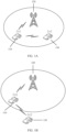
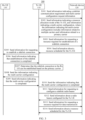
- FIG. 1A and FIG. 1B show two application scenarios according to an embodiment of this application.
- Tx UE 110, a network device 120, and Rx UE 130 are involved.
- the Tx UE 110 may first request, from the network device 120, a resource required for communication. Then, the Tx UE 110 sends control information and data information to the Rx UE 130 based on a resource allocated by the network device. Different from that in FIG. 1B , in FIG. 1A , both the Tx UE 110 and the Rx UE 130 are located within coverage of the network device 120.
- FIG. 1A both the Tx UE 110 and the Rx UE 130 are located within coverage of the network device 120.
- the Tx UE 110 is located within coverage of the network device 120; however, the Rx UE 130 is located outside coverage of the network device 120. It should be noted that although in FIG. 1A and FIG. 1B , the Tx UE 110 is shown to communicate with only one Rx UE 130, the Tx UE 110 may also communicate with a plurality of different pieces of Rx UE 130. Embodiments of this application is applicable to communication between the Tx UE 110 and each piece of Rx UE 130.
- sidelink communication between the Tx UE 110 and the Rx UE 130 supports only a single carrier, and the resource that is configured by the network device 120 for the Tx UE 110 and that is used for sidelink communication also includes only a single-carrier resource.
- the Tx UE 110 has a large data communication requirement, communication quality of the Tx UE 110 is to be limited.
- 4G LTE V2X although sidelink communication between the Tx UE 110 and the Rx UE 130 already supports multiple carriers, the multiple carriers are only for a broadcast scenario. In other words, the Tx UE 110 sends broadcast data on the multiple carriers configured by the network device 120, and interested Rx UE 130 is to perform monitoring.
- a carrier aggregation (carrier aggregation, CA) technology is introduced.
- CA carrier aggregation
- a plurality of LTE component carriers (component carrier, CC) may be aggregated, to effectively improve uplink and downlink transmission rates.
- a component carrier accessed by UE is referred to as a primary carrier, and other component carriers are referred to as secondary carriers.
- An uplink carrier and a corresponding downlink carrier form a cell (Cell).
- the primary carrier is a primary cell (Primary Cell, PCell)
- a secondary carrier is a secondary cell (Secondary Cell, SCell).
- the Tx UE 110 may request the network device 120 to configure multiple carriers for sidelink communication between the Tx UE 110 and the Rx UE 130; the network device 120 may configure multiple carriers for the Tx UE 110 based on the request from the Tx UE 110; and the Tx UE 110 and the Rx UE 130 may be set based on information about the multiple carriers configured by the network device 120, to perform sidelink communication by using the multiple carriers.
- resources used for sidelink communication increase, and communication quality can be ensured even if there is a large data communication requirement.
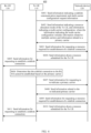
- FIG. 2 is a schematic flowchart of a wireless communication method 200 according to an embodiment of this application. As shown in FIG. 2 , the wireless communication method 200 may include the following steps.
- Tx UE 110 sends multi-carrier configuration request information to a network device 120.
- the multiple carriers requested for configuration are used for sidelink communication between the Tx UE 110 and Rx UE 130.
- the network device 120 sends, to the Tx UE 110, information indicating a multi-carrier configuration.
- the information that indicates the multi-carrier configuration and that is sent by the network device 120 to the Tx UE 110 includes information related to multiple carriers configured by the network device for the Tx UE 110.
- Tx UE 110 before establishing a sidelink connection to Rx UE 130, requests a network device 120 to configure multiple carriers.
- the network device 120 configures, based on the request from the Tx UE 110, multiple carriers for sidelink communication between the Tx UE 110 and the Rx UE 130, and indicates one of the multiple carriers to be used as a primary carrier for establishing the sidelink connection between the Tx UE 110 and the Rx UE 130.
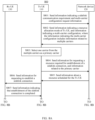
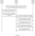
- FIG. 3 is a schematic flowchart of a wireless communication method 300 according to Embodiment 1 of this application.
- the Tx UE 110 can establish a sidelink connection to Rx UE 130 based on a primary carrier.
- the wireless communication method 300 may include the following steps.
- the Tx UE 110 sends a first message to a network device 120, where the first message includes information indicating a sidelink communication requirement and multi-carrier configuration request information. It may be understood that the first message may be determined by the Tx UE 110, or may be determined by the Rx UE 130, and then is sent to the Tx UE 110. A specific manner of determining the first message is not limited in this embodiment of this application.
- the first message may include any one of a SidelinkUEInformation Message and a SidelinkUEInformationNR Message that are defined in 3GPP (3rd Generation Partnership Project, 3rd generation partnership project) TS 36.331, and a SidelinkUEInformationEUTRA Message and a SidelinkUEInformationNR Message (collectively referred to as a SidelinkUEInformation type message below) that are defined in TS 38.331.
- the SidelinkUEInformation type message is used by user equipment to indicate sidelink-related information to a network device (for example, a base station).
- information indicating a sidelink communication requirement may include information indicating a frequency that the user equipment has interest in and that is used to transmit and receive sidelink communication, information indicating a destination list, and the like.
- the Tx UE 110 may request, by using the SidelinkUEInformation type message, the network device 120 to configure multiple carriers in the following several forms.
- the Tx UE 110 may send, in two different messages, the information indicating the sidelink communication requirement and the multi-carrier configuration request information.
- a message used to send the information indicating the sidelink communication requirement may include the SidelinkUEInformation type message
- a message used to send the multi-carrier configuration request information may include a UEAssistanceInformation Message defined in 3GPP TS 36.331 or 38.331, or a new message that has not been defined in 3GPP TS.
- the UEAssistanceInformation Message is used by user equipment to indicate auxiliary information of the user equipment to a network device (for example, a base station).
- the UEAssistanceInformation message may include information indicating a preference of the user equipment for a maximum physical downlink shared channel (Physical Downlink Shared Channel, PDSCH) bandwidth configuration, information indicating an excessive quantity of repetitions on an MTC physical downlink control channel (Machine-Type Communication (MTC) Physical Downlink Control Channel, MPDCCH), information indicating a service feature of an uplink logical channel, and the like.
- PDSCH Physical Downlink Shared Channel
- MPDCCH Physical Downlink Control Channel
- the network device 120 For a form in which the Tx UE 110 requests, by using the UEAssistanceInformation Message or a newly defined message, the network device 120 to configure multiple carriers, refer to the foregoing descriptions of the SidelinkUEInformation type message. Details are not described herein again.
- the Tx UE 110 may not send the multi-carrier configuration request information to the network device 120, but the network device 120 determines whether multiple carriers need to be configured for the Tx UE 110.
- the network device 120 sends a second message to the Tx UE 110, where the second message includes information indicating that a resource allocation mode of the Tx UE 110 is a resource allocation mode scheduled by a base station, and information indicating a multi-carrier configuration, where the information indicating the multi-carrier configuration includes information related to multiple carriers configured by the network device 120 for the Tx UE 110 and information related to a primary carrier (or referred to as a primary cell).
- the second message includes an RRCConnectionReconfiguration Message defined in 3GPP TS 36.331 or an RRCReconfiguration Message defined in 3GPP TS 38.331.
- content of an IE (information element, information element) "SL-V2X-ConfigDedicated" may indicate that a resource allocation mode of the Tx UE 110 is a resource allocation mode based on scheduling by a base station or a resource allocation manner based on autonomous selection.
- the second message may include a new message that has not been defined in 3GPP TS.
- the information indicating the multi-carrier configuration may include identifiers of the multiple carriers configured by the network device 120 for the Tx UE 110, for example, but not limited to, a carrier ID (Identifier, identifier), a cell index, and a number.
- the information indicating the multi-carrier configuration may further include a parameter configuration of the carrier, for example, a frequency band, a frequency, bandwidth, and a subcarrier spacing.
- the information indicating the multi-carrier configuration may further additionally include: information that the network device 120 indicates, from the multiple carriers, one carrier as the primary carrier, or information directly indicating the primary carrier.
- the Tx UE 110 may distinguish between the primary carrier and a secondary carrier (or a secondary cell) in the foregoing plurality of carriers based on these pieces of information related to the primary carrier, where the primary carrier is to be used for establishing a sidelink connection between the Tx UE 110 and the Rx UE 130, and the secondary carrier is to be used for providing an additional radio resource for sidelink communication between the Tx UE 110 and the Rx UE 130.
- the network device 120 may specify the second ID in the IDs of the multiple carriers as an ID of the primary carrier.
- the information that the network device 120 indicates, from the multiple carriers, one carrier as the primary carrier may be "2".
- the network device 120 may additionally and directly indicate a cell index of the primary carrier.
- the information indicating the multi-carrier configuration may not additionally include: information indicating, by the network device 120 from the multiple carriers, one carrier as the primary carrier, or information directly indicating the primary carrier.
- the network device 120 may directly indicate information about the primary carrier by using an identifier of the carrier.
- an indication rule for a primary carrier may be considered by default.
- the first ID in the IDs of the foregoing plurality of carriers may be considered as an ID of the primary carrier by default.
- the information indicating the multi-carrier configuration may further additionally include an identifier of the Rx UE 130, and the identifier of the Rx UE 130 is used to indicate that the multiple carriers configured by the network device 120 are used for sidelink communication between the Tx UE 110 and a specified piece of Rx UE 130.
- the identifier of the Rx UE 130 may include, but is not limited to, a destination layer-2 identifier (destination layer-2 ID) of the Rx UE 130, an index of the Rx UE 130 that is in a plurality of pieces of Rx UE communicating with the Tx UE 110, and the like.
- the information indicating the initial states of the multiple carriers may not include information indicating an activated or a deactivated state of the primary carrier, but include information indicating an activated or a deactivated state of each secondary carrier.
- the network device 120 may indicate the initial states of the multiple carriers in the following several manners.
- a character string "activated” may be used to indicate that a carrier is configured to be in an activated state
- a character string "deactivated” is used to indicate that a carrier is configured to be in a deactivated state.
- each character string indicating the activated or deactivated state of each carrier or each secondary carrier may be located before or after the identifier of each carrier or each secondary carrier.
- character strings indicating the activated or deactivated state of all carriers or all secondary carriers may be located before or after the identifiers of the multiple carriers, and an arrangement order of the character strings may correspond to an arrangement order of the identifiers of the multiple carriers.
- only an identifier of a carrier configured to be in an activated state may be indicated, or only an identifier of a carrier configured to be in a deactivated state may be indicated.
- one bit may be used to indicate that the multiple carriers are all configured to be in an activated state. For example, when a value of the bit is "1", it indicates that the multiple carriers are all configured to be in an activated state. Alternatively, when a value of the bit is "0", it indicates that the multiple carriers are all configured to be in an activated state.
- one character string "activated" may alternatively be used to indicate that the multiple carriers are all configured to be in an activated state.
- one character string "deactivated" may alternatively be used to indicate that the multiple carriers are all configured to be in an activated state.
- the network device 120 may determine whether multiple carriers need to be configured for the Tx UE 110. In an example, the network device 120 may determine, based on historical resource usage of the Tx UE 110, a BSR reported by the Tx UE 110, a current idle resource, and the like, whether multiple carriers need to be configured for the Tx UE 110.
- the Tx UE 110 may perform setting based on the information that is received from the network device 120 and that indicates the multi-carrier configuration, to perform sidelink communication on at least one carrier (including the primary carrier) that is configured to be in an activated state and that is in the multiple carriers. For example, the Tx UE 110 may add, based on a parameter configuration of each carrier in the multiple carriers, each carrier corresponding to an identifier of each carrier.
- the network device 120 sends, to the Tx UE 110, information indicating a resource scheduled by the network device 120 for the Tx UE 110, where the resource is related to the primary carrier and is to be used for establishing the sidelink connection between the Tx UE 110 and the Rx UE 130.
- the network device 120 may schedule the resource based on the BSR reported by the Tx UE 110.
- the network device 120 may send, to the Tx UE 110 by using a PDCCH, the information indicating the resource scheduled by the network device 120 for the Tx UE 110.
- the Tx UE 110 sends, to the Rx UE 130 based on the resource that is related to the primary carrier and that is allocated by the network device 120, information for requesting to establish a sidelink connection.
- the Rx UE 130 sends, to the Tx UE 110, information indicating that establishment of the sidelink connection is completed.
- the Tx UE 110 determines that the sidelink connection to the Rx UE 130 can be established based on the primary carrier.
- the Tx UE 110 determines that the information indicating that establishment of the sidelink connection is completed is received from the Rx UE 130 within a threshold time period after the information for requesting to establish a sidelink connection is sent to the Rx UE 130, the Tx UE 110 determines that the sidelink connection to the Rx UE 130 can be established based on the primary carrier.
- the threshold time period may be 10 seconds, 30 seconds, 1 minute, or the like. A specific value of the threshold time period is not limited in this embodiment of this application.
- the threshold time period may be preset in advance, or may be negotiated between the Tx UE and the Rx UE.
- the Tx UE 110 determines that the sidelink connection to the Rx UE 130 can be established based on the primary carrier, the Tx UE 110 does not need to request the network device 120 to re-indicate a primary carrier.
- the Tx UE 110 sends a third message to the Rx UE 130, where the third message includes the information indicating the multi-carrier configuration.
- the third message may include, but is not limited to, an RRCReconfigurationSidelink Message that is on a PC5 interface and that is defined in 3GPP TS 38.331, or another new message that has not been defined in 3GPP TS.
- the information that indicates the multi-carrier configuration and that is sent by the Tx UE 110 to the Rx UE 130 may include an identifier of at least one secondary carrier in the multiple carriers configured by the network device 120 for the Tx UE 110, for example, but not limited to, a carrier ID and a cell index.
- the information that indicates the multi-carrier configuration and that is sent by the Tx UE 110 to the Rx UE 130 may further include a parameter configuration of the secondary carrier, for example, a frequency band, a frequency, bandwidth, and a subcarrier spacing.
- the information that indicates the multi-carrier configuration and that is sent by the Tx UE 110 to the Rx UE 130 may further additionally include information indicating an initial state of each secondary carrier, and the information indicating the initial state of each secondary carrier may include information indicating an activated or a deactivated state of each secondary carrier.
- the Tx UE 110 indicates the initial state of each secondary carrier, refer to the related descriptions in S302. Details are not described herein again.
- the Rx UE 130 sends a fourth message to the Tx UE 110, where the fourth message includes information indicating that the multi-carrier configuration is completed, to indicate, to the Tx UE 110, that the Rx UE 130 has completed the multi-carrier configuration.
- the fourth message may include, but is not limited to, an RRCReconfigurationCompleteSidelink Message that is on a PC5 interface and that is defined in 3GPP TS 38.331, or another new message that has not been defined in 3GPP TS.
- the Rx UE 130 may perform setting based on the information that is received from the Tx UE 110 and that indicates the multi-carrier configuration, to perform sidelink communication on at least one secondary carrier that is configured to be in an activated state. For example, the Rx UE 130 may add, based on a parameter configuration of each secondary carrier in the at least one secondary carrier that is configured to be in an activated state, each secondary carrier corresponding to an identifier of each secondary carrier.
- the Tx UE 110 sends a fifth message to the network device 120, where the fifth message includes the information indicating that the multi-carrier configuration is completed, to indicate, to the network device 120, that the Tx UE 110 and the Rx UE 130 have completed the multi-carrier configuration.
- the fifth message may include an RRCConnectionReconfigurationComplete Message defined in 3GPP TS 36.331 or an RRCReconfigurationComplete Message defined in 3GPP TS 38.331.
- the fifth message may include a new message that has not been defined in 3GPP TS.
- the Tx UE 110 When the Tx UE 110 has data to transmit to the Rx UE 130, the Tx UE 110 sends a sixth message to the network device 120, where the sixth message includes information for requesting to establish a sidelink radio bearer.
- the sixth message may include the SidelinkUEInformation type message or another new message that has not been defined in 3GPP TS.
- the network device 120 sends a seventh message to the Tx UE 110, where the seventh message includes information indicating a radio bearer configured by the network device 120 for the Tx UE 110.
- the seventh message may include an RRCConnectionReconfiguration Message defined in 3GPP TS 36.331 or an RRCReconfiguration Message defined in 3GPP TS 38.331.
- the seventh message may include a new message that has not been defined in 3GPP TS.
- the Tx UE 110 sends, to the network device 120, information for requesting a resource required for data transmission, for example, an SR and a BSR, where the SR is used by the Tx UE 110 to indicate, to the network device 120, that the Tx UE 110 has data to transmit, and the BSR is used by the Tx UE 110 to indicate, to the network device 120, a volume of the data to be transmitted by the Tx UE 110.
- a resource required for data transmission for example, an SR and a BSR
- the network device 120 sends, to the Tx UE 110, information indicating a resource scheduled by the network device 120 for the Tx UE 110, where the resource is used by the Tx UE 110 to send data to the Rx UE 130 based on the radio bearer configured by the network device 120, and the network device 120 may schedule the resource based on the BSR reported by the Tx UE 110.
- S401 The Tx UE 110 sends a first message to the network device 120, where the first message includes information indicating a sidelink communication requirement and multi-carrier configuration request information.
- the step is the same as S301 in FIG. 3 .
- S301 For details, refer to the descriptions of S301. Details are not described herein again.
- the Tx UE 110 may use one bit to indicate that the Tx UE 110 fails to indicate the network device 120 to establish the sidelink connection.
- a value of the bit may be "1" or "0".
- a non-numeric character string is used to indicate that the Tx UE 110 fails to indicate the network device 120 to establish the sidelink connection.
- the non-numeric character string is, but is not limited to, an enumerated type value Enumerated ⁇ failure ⁇ .
- the ninth message may include, but is not limited to, an RRCConnectionReconfiguration Message defined in 3GPP TS 36.331, an RRCReconfiguration Message defined in 3GPP TS 38.331, or a new message that has not been defined in 3GPP TS.
- the information related to the re-indicated primary carrier may include: information indicating, by the network device 120, another carrier as the new primary carrier from the multiple carriers configured for the Tx UE 110, or information directly indicating the new primary carrier.
- the network device 120 may specify the third ID in the IDs of the multiple carriers as an ID of the new primary carrier.
- the information that the network device 120 indicates, from the multiple carriers, another carrier as the new primary carrier may be represented as "3".
- the network device 120 may additionally and directly indicate an ID or a cell index of the new primary carrier.
- the information related to the re-indicated primary carrier may further additionally include information indicating an activated state of the primary carrier.
- the network device 120 may indicate, in the ninth message, the activated state of the primary carrier by using one bit whose value is "1" or whose value is "0"; or a character string "activated” is used to indicate the activated state of the primary carrier.
- the information related to the re-indicated primary carrier may not include the information indicating the activated state of the primary carrier.
- S409 The Tx UE 110 sends, to the network device 120, information for requesting a resource required for establishment of a sidelink connection.
- the step is the same as S303 in FIG. 3 .
- S303 For details, refer to the descriptions of S303. Details are not described herein again.
- the Tx UE 110 may modify the setting based on the information that is received from the network device 120 and that is related to the re-indicated primary carrier, to perform sidelink communication on the re-indicated primary carrier.
- the network device 120 sends, to the Tx UE 110, information indicating a resource scheduled by the network device 120 for the Tx UE 110, where the resource is related to the re-indicated primary carrier and is to be used for establishing the sidelink connection between the Tx UE 110 and the Rx UE 130.
- the step is the same as S304 in FIG. 3 .
- S304 refer to the descriptions of S304. Details are not described herein again.
- the Tx UE 110 sends, to the Rx UE 130 based on the resource that is related to the re-indicated primary carrier and that is allocated by the network device 120, information for requesting to establish a sidelink connection.
- step S411 if the Tx UE 110 determines that the sidelink connection to the Rx UE 130 can be established based on the re-indicated primary carrier, S308 to S314 in FIG. 3 may continue to be performed; or if the Tx UE 110 determines that the sidelink connection to the Rx UE 130 cannot be established based on the re-indicated primary carrier, S407 to S411 in FIG. 4 may be performed again.
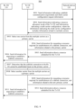
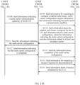
- FIG. 5A and FIG. 5B are a schematic flowchart of a wireless communication method 500 for Tx UE 110 according to Embodiment 1 of this application.
- steps performed by the Tx UE 110 include the steps that are related to the Tx UE 110 and that are shown in FIG. 3 and FIG. 4 .
- the wireless communication method 500 may include the following steps.
- S501 Generate information indicating a sidelink communication requirement and multi-carrier configuration request information, and send these pieces of information to a network device 120 by using a first message. For this step, refer to the descriptions of S301 in FIG. 3 . Details are not described herein again.
- S502 Receive a second message from the network device 120, where the second message includes information indicating that a resource allocation mode of the Tx UE 110 is a resource allocation mode scheduled by a base station, and information indicating a multi-carrier configuration, where the information indicating the multi-carrier configuration includes information related to multiple carriers configured by the network device 120 for the Tx UE 110 and information related to a primary carrier.
- the second message includes information indicating that a resource allocation mode of the Tx UE 110 is a resource allocation mode scheduled by a base station, and information indicating a multi-carrier configuration, where the information indicating the multi-carrier configuration includes information related to multiple carriers configured by the network device 120 for the Tx UE 110 and information related to a primary carrier.
- S503 Perform setting based on the information that is from the network device 120 and that indicates the multi-carrier configuration, to perform sidelink communication on at least one carrier (including the primary carrier) that is configured to be in an activated state and that is in the multiple carriers.
- the Tx UE 110 may add, based on a parameter configuration of each carrier in the multiple carriers, each carrier corresponding to an identifier of each carrier.
- S504 Send, to the network device 120, information for requesting a resource required for establishment of a sidelink connection. For this step, refer to the descriptions of S303 in FIG. 3 . Details are not described herein again.
- S505 Receive, from the network device 120, information indicating a resource scheduled by the network device 120 for the Tx UE 110, where the resource is related to the primary carrier and is to be used for establishing a sidelink connection between the Tx UE 110 and the Rx UE 130.
- the resource is related to the primary carrier and is to be used for establishing a sidelink connection between the Tx UE 110 and the Rx UE 130.
- S506 Send, to the Rx UE 130 based on the resource that is related to the primary carrier and that is allocated by the network device 120, information for requesting to establish a sidelink connection.
- S507 Determine whether the sidelink connection to the Rx UE 130 can be established based on the primary carrier; and if the sidelink connection to the Rx UE 130 can be established based on the primary carrier, perform S508 to S514; or if the sidelink connection to the Rx UE 130 cannot be established based on the primary carrier, perform S515 and S516.
- the Tx UE 110 determines that the information indicating that establishment of the sidelink connection is completed is received from the Rx UE 130 within a threshold time period after the information for requesting to establish a sidelink connection is sent to the Rx UE 130, the Tx UE 110 determines that the sidelink connection to the Rx UE 130 can be established based on the primary carrier. If the Tx UE 110 determines that the information indicating that establishment of the sidelink connection is completed is not received from the Rx UE 130 within a threshold time period after the information for requesting to establish a sidelink connection is sent to the Rx UE 130, the Tx UE 110 determines that the sidelink connection to the Rx UE 130 cannot be established based on the primary carrier.
- the threshold time period may be 10 seconds, 30 seconds, 1 minute, or the like.
- a specific value of the threshold time period is not limited in this embodiment of this application.
- the threshold time period may be preset in advance, or may be negotiated between the Tx UE and the Rx UE.
- S508 Send a third message to the Rx UE 130, where the third message includes the information indicating the multi-carrier configuration.
- the third message includes the information indicating the multi-carrier configuration.
- S509 Receive a fourth message from the Rx UE 130, where the fourth message includes information indicating that the multi-carrier configuration is completed, and the message may indicate, to the Tx UE 110, that the Rx UE 130 has completed the multi-carrier configuration. For this step, refer to the descriptions of S309 in FIG. 3 . Details are not described herein again.
- S510 Send a fifth message to the network device 120, where the fifth message includes the information indicating that the multi-carrier configuration is completed, to indicate, to the network device 120, that the Tx UE 110 and the Rx UE 130 have completed the multi-carrier configuration.
- the fifth message includes the information indicating that the multi-carrier configuration is completed, to indicate, to the network device 120, that the Tx UE 110 and the Rx UE 130 have completed the multi-carrier configuration.
- S511 When there is data to transmit to the Rx UE 130, send a sixth message to the network device 120, where the sixth message includes information for requesting to establish a sidelink radio bearer. For this step, refer to the descriptions of S311 in FIG. 3 . Details are not described herein again.
- S512 Receive a seventh message from the network device 120, where the seventh message includes information indicating a radio bearer configured by the network device 120 for the Tx UE 110. For this step, refer to the descriptions of S312 in FIG. 3 . Details are not described herein again.
- S513 Send, to the network device 120, information for requesting a resource required for data transmission, for example, an SR and a BSR, where the SR is used by the Tx UE 110 to indicate, to the network device 120, that the Tx UE 110 has data to transmit, and the BSR is used by the Tx UE 110 to indicate, to the network device 120, a volume of the data to be transmitted by the Tx UE 110.
- a resource required for data transmission for example, an SR and a BSR
- S514 Receive, from the network device 120, information indicating a resource scheduled by the network device 120 for the Tx UE 110, where the resource is used by the Tx UE 110 to send data to the Rx UE 130 based on the radio bearer configured by the network device 120.
- S515 Send an eighth message to the network device 120, where the eighth message includes information for requesting to re-indicate a primary carrier.
- the eighth message includes information for requesting to re-indicate a primary carrier.
- the Tx UE 110 may not send, to the network device 120, the information for requesting to re-indicate a primary carrier, but send information indicating a failure in establishing the sidelink connection, where the information indicating a failure in establishing the sidelink connection is used by the Tx UE 110 to indicate, to the network device 120, that the Tx UE 110 fails to establish the sidelink connection to the Rx UE 130.
- the Tx UE 110 may send, to the network device 120, both the information for requesting to re-indicate a primary carrier and information indicating a failure in establishing the sidelink connection.
- the Tx UE 110 may use one bit to indicate that the Tx UE 110 fails to indicate the network device 120 to establish the sidelink connection.
- a value of the bit may be "1" or "0".
- a non-numeric character string is used to indicate that the Tx UE 110 fails to indicate the network device 120 to establish the sidelink connection.
- the non-numeric character string is, but is not limited to, an enumerated type value Enumerated ⁇ failure ⁇ .
- S516 Receive a ninth message from the network device 120, where the ninth message includes information related to a re-indicated primary carrier. For this step, refer to the descriptions of S408 in FIG. 4 . Details are not described herein again.
- the setting may be further modified based on the information that is received from the network device 120 and that is related to the re-indicated primary carrier, to perform sidelink communication on the re-indicated primary carrier.
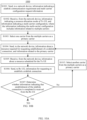
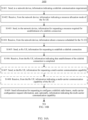
- FIG. 6 is a schematic flowchart of a wireless communication method 600 for a network device 120 according to Embodiment 1 of this application.
- steps performed by the network device 120 include the steps that are related to the network device 120 and that are shown in FIG. 3 and FIG. 4 .
- the wireless communication method 600 may include the following steps.
- S601 Receive a first message from Tx UE 110, where the first message includes information indicating a sidelink communication requirement and multi-carrier configuration request information. For this step, refer to the descriptions of S301 in FIG. 3 . Details are not described herein again.
- S602 Configure, based on a request from the Tx UE 110, multiple carriers for sidelink communication between the Tx UE 110 and Rx UE 130.
- the network device 120 may determine whether multiple carriers need to be configured for the Tx UE 110. In an example, the network device 120 may determine, based on historical resource usage of the Tx UE 110, a BSR reported by the Tx UE 110, a current idle resource, and the like, whether multiple carriers need to be configured for the Tx UE 110.
- S603 Send a second message to the Tx UE 110, where the second message includes information indicating that a resource allocation mode of the Tx UE 110 is a resource allocation mode scheduled by a base station, and information indicating a multi-carrier configuration, where the information indicating the multi-carrier configuration includes information related to the multiple carriers configured by the network device 120 for the Tx UE 110 and information related to a primary carrier (or referred to as a primary cell).
- a primary carrier or referred to as a primary cell
- S604 Receive, from the Tx UE 110, information for requesting a resource required for establishment of a sidelink connection, where the requested resource is related to the primary carrier indicated by the network device 120. For this step, refer to the descriptions of S303 in FIG. 3 . Details are not described herein again.
- S605 Send, to the Tx UE 110, information indicating a resource scheduled by the network device 120 for the Tx UE 110, where the resource is related to the primary carrier indicated by the network device 120 and is to be used for establishing the sidelink connection between the Tx UE 110 and the Rx UE 130.
- the resource may be scheduled based on the BSR reported by the Tx UE 110. For this step, refer to the descriptions of S304 in FIG. 3 . Details are not described herein again.
- S606 Optionally, receive an eighth message from the Tx UE 110, where the eighth message includes information for requesting to re-indicate a primary carrier.
- the eighth message includes information for requesting to re-indicate a primary carrier.
- the eighth message includes information for requesting to re-indicate a primary carrier.
- the information for requesting to re-indicate a primary carrier may not be included, but information indicating a failure in establishing the sidelink connection is included, where the information indicating a failure in establishing the sidelink connection is used by the Tx UE 110 to indicate, to the network device 120, that the Tx UE 110 fails to establish the sidelink connection to the Rx UE 130.
- both the information for requesting to re-indicate a primary carrier and information indicating a failure in establishing the sidelink connection may be included.
- the Tx UE 110 may use one bit to indicate that the Tx UE 110 fails to indicate the network device 120 to establish the sidelink connection.
- a value of the bit may be "1" or "0".
- a non-numeric character string is used to indicate that the Tx UE 110 fails to indicate the network device 120 to establish the sidelink connection.
- the non-numeric character string is, but is not limited to, an enumerated type value Enumerated ⁇ failure ⁇ .
- S607 Optionally, send a ninth message to the Tx UE 110, where the ninth message includes information related to a re-indicated primary carrier.
- the ninth message includes information related to a re-indicated primary carrier.
- S608 Optionally, receive, from the Tx UE 110, information for requesting a resource required for establishment of a sidelink connection, where the requested resource is related to the primary carrier re-indicated by the network device 120.
- the requested resource is related to the primary carrier re-indicated by the network device 120.
- S609 Optionally, send, to the Tx UE 110, information indicating a resource scheduled by the network device 120 for the Tx UE 110, where the resource is related to the re-indicated primary carrier and is to be used for establishing the sidelink connection between the Tx UE 110 and the Rx UE 130.
- the resource may be scheduled based on the BSR reported by the Tx UE 110. For this step, refer to the descriptions of S304 in FIG. 3 . Details are not described herein again.
- S610 Receive a fifth message from the Tx UE 110, where the fifth message includes the information indicating that the multi-carrier configuration is completed, and the message may indicate, to the network device 120, that the Tx UE 110 and the Rx UE 130 have completed the multi-carrier configuration.
- the fifth message includes the information indicating that the multi-carrier configuration is completed, and the message may indicate, to the network device 120, that the Tx UE 110 and the Rx UE 130 have completed the multi-carrier configuration.
- the fifth message includes the information indicating that the multi-carrier configuration is completed, and the message may indicate, to the network device 120, that the Tx UE 110 and the Rx UE 130 have completed the multi-carrier configuration.
- S611 Receive a sixth message from the Tx UE 110, where the sixth message includes information for requesting to establish a sidelink radio bearer. For this step, refer to the descriptions of S311 in FIG. 3 . Details are not described herein again.
- S612 Send a seventh message to the Tx UE 110, where the seventh message includes information indicating a radio bearer configured by the network device 120 for the Tx UE 110.
- the seventh message includes information indicating a radio bearer configured by the network device 120 for the Tx UE 110.
- the seventh message includes information indicating a radio bearer configured by the network device 120 for the Tx UE 110.
- S312 in FIG. 3 Details are not described herein again.
- S613 Receive, from the Tx UE 110, information for requesting a resource required for data transmission, for example, an SR and a BSR, where the SR is used by the Tx UE 110 to indicate, to the network device 120, that the Tx UE 110 has data to transmit, and the BSR is used by the Tx UE 110 to indicate, to the network device 120, a volume of the data to be transmitted by the Tx UE 110.
- a resource required for data transmission for example, an SR and a BSR
- S614 Send, to the Tx UE 110, information indicating a resource scheduled by the network device 120 for the Tx UE 110, where the resource is used by the Tx UE 110 to send data to the Rx UE 130 based on the radio bearer configured by the network device 120, and the resource may be scheduled based on the BSR reported by the Tx UE 110.
- the resource is used by the Tx UE 110 to send data to the Rx UE 130 based on the radio bearer configured by the network device 120, and the resource may be scheduled based on the BSR reported by the Tx UE 110.
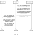
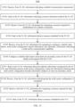
- FIG. 7 is a schematic flowchart of a wireless communication method 700 for Rx UE 130 according to Embodiment 1 of this application.
- steps performed by the Rx UE 130 include the steps that are related to the Rx UE 130 and that are shown in FIG. 3 and FIG. 4 .
- the wireless communication method 700 may include the following steps.
- S701 Receive, from Tx UE 110, information for requesting to establish a sidelink connection.
- S702 Send, to the Tx UE 110, information indicating that establishment of the sidelink connection is completed.
- S703 Receive a third message from the Tx UE 110, where the third message includes information indicating a multi-carrier configuration. For this step, refer to the descriptions of S308 in FIG. 3 . Details are not described herein again.
- S704 Perform setting based on the information that is from the Tx UE 110 and that indicates the multi-carrier configuration, to perform sidelink communication on at least one secondary carrier configured to be in an activated state.
- the Rx UE 130 may add, based on a parameter configuration of each secondary carrier in the at least one secondary carrier that is configured to be in an activated state, each secondary carrier corresponding to an ID or a cell index of each secondary carrier.
- S705 Send a fourth message to the Tx UE 110, where the fourth message includes information indicating that the multi-carrier configuration is completed, to indicate, to the Tx UE 110, that the Rx UE 130 has completed the multi-carrier configuration.
- the fourth message includes information indicating that the multi-carrier configuration is completed, to indicate, to the Tx UE 110, that the Rx UE 130 has completed the multi-carrier configuration.
- Tx UE 110 before establishing a sidelink connection to Rx UE 130, requests a network device 120 to configure multiple carriers.
- the network device 120 configures, based on the request from the Tx UE 110, multiple carriers for sidelink communication between the Tx UE 110 and the Rx UE 130.
- the Tx UE 110 selects, from the multiple carriers, one carrier as a primary carrier for establishing the sidelink connection to the Rx UE 130.
- FIG. 8A and FIG. 8B are a schematic flowchart of a wireless communication method 800 according to Embodiment 2 of this application.
- the Tx UE 110 can establish a sidelink connection to Rx UE 130 based on a selected primary carrier.
- the wireless communication method 800 may include the following steps.
- S801 The Tx UE 110 sends a first message to a network device 120, where the first message includes information indicating a sidelink communication requirement and multi-carrier configuration request information.
- the first message includes information indicating a sidelink communication requirement and multi-carrier configuration request information.
- the Tx UE 110 may not send the multi-carrier configuration request information to the network device 120, but the network device 120 determines whether multiple carriers need to be configured for the Tx UE 110.
- the network device 120 sends a second message to the Tx UE 110, where the second message includes information indicating that a resource allocation mode of the Tx UE 110 is a resource allocation mode scheduled by a base station, and information indicating a multi-carrier configuration, where the information indicating the multi-carrier configuration includes information related to multiple carriers configured by the network device 120 for the Tx UE 110.
- the second message includes an RRCConnectionReconfiguration Message defined in 3GPP TS 36.331 or an RRCReconfiguration Message defined in 3GPP TS 38.331.
- content of an IE (information element, information element) "SL-V2X-ConfigDedicated" may indicate that a resource allocation mode of the Tx UE 110 is a resource allocation mode based on scheduling by a base station or a resource allocation manner based on autonomous selection.
- the second message may include a new message that has not been defined in 3GPP TS.
- the information indicating the multi-carrier configuration may include identifiers of the multiple carriers configured by the network device 120 for the Tx UE 110, for example, but not limited to, a carrier ID (Identifier, identifier) and a cell index.
- the information indicating the multi-carrier configuration may further include a parameter configuration of the carrier, for example, a frequency band, a frequency, bandwidth, and a subcarrier spacing.
- the information indicating the multi-carrier configuration may additionally include an identifier of the Rx UE 130, for example, but not limited to, a destination layer-2 identifier (destination layer-2 ID) of the Rx UE 130, and an index of the Rx UE 130 in a plurality of pieces of Rx UE communicating with the Tx UE 110.
- the identifier of the Rx UE 130 is used to indicate that the multiple carriers configured by the network device 120 are used for sidelink communication between the Tx UE 110 and a specified piece of Rx UE 130.
- the information indicating the multi-carrier configuration may further additionally include information indicating initial states of the multiple carriers, and the information indicating the initial states of the multiple carriers may include information indicating an activated or a deactivated state of each carrier in the multiple carriers.
- the Tx UE 110 needs to select, from the multiple carriers, one carrier as a primary carrier for establishing a sidelink communication connection to the Rx UE 130. Therefore, the network device 120 may configure all the multiple carriers to be in an activated state. In this way, when the Tx UE 110 has a data transmission requirement, a step of activating each carrier may be omitted, so that the Tx UE 110 obtains a transmission resource more quickly.
- the network device 120 may indicate the initial states of the multiple carriers in the following several manners.
- a character string "activated" may be used to indicate that a carrier is configured to be in an activated state.
- each character string indicating the activated state of each carrier may be located before or after an identifier of each carrier.
- character strings indicating the activated state of all carriers may be located before or after a plurality of identifiers of the multiple carriers, and an arrangement sequence of the character strings may correspond to an arrangement sequence of the plurality of identifiers of the multiple carriers.
- an identifier of a carrier configured to be in an activated state may be indicated.
- One bit may be used to indicate that the multiple carriers are all configured to be in an activated state. For example, when a value of the bit is "1", it indicates that the multiple carriers are all configured to be in an activated state. Alternatively, when a value of the bit is "0", it indicates that the multiple carriers are all configured to be in an activated state.
- one character string "activated" may alternatively be used to indicate that the multiple carriers are all configured to be in an activated state.
- the network device 120 may alternatively separately send the information indicating that the resource allocation mode of the Tx UE 110 is the resource allocation mode scheduled by a base station, and the information indicating the multi-carrier configuration.
- the network device 120 may send the two types of information by using two RRCReconfiguration messages.
- the network device 120 may determine whether multiple carriers need to be configured for the Tx UE 110. In an example, the network device 120 may determine, based on historical resource usage of the Tx UE 110, a BSR reported by the Tx UE 110, a current idle resource, and the like, whether multiple carriers need to be configured for the Tx UE 110.
- the Tx UE 110 selects, from the multiple carriers indicated in the information indicating the multi-carrier configuration, one carrier as a primary carrier, and other carriers are to be used as secondary carriers, where the primary carrier is to be used for establishing a sidelink connection between the Tx UE 110 and the Rx UE 130, and the secondary carrier is to be used for providing an additional radio resource for sidelink communication between the Tx UE 110 and the Rx UE 130.
- the Tx UE 110 may perform signal quality measurement on the multiple carriers indicated in the information indicating the multi-carrier configuration, and select, from the multiple carriers, one carrier with a best signal quality as the primary carrier.
- the Tx UE 110 may perform setting based on the information that is received from the network device 120 and that indicates the multi-carrier configuration, to perform sidelink communication on the multiple carriers that are configured to be in an activated state. For example, the Tx UE 110 may add, based on a parameter configuration of each carrier in the multiple carriers, each carrier corresponding to an identifier of each carrier.
- the Tx UE 110 sends, to the network device 120, information for requesting a resource required for establishment of a sidelink connection, and information related to the primary carrier selected by the Tx UE 110.
- the information for requesting the resource required for establishment of the sidelink connection may include an SR (scheduling request, scheduling request) and a BSR (buffer status report, buffer status report).
- the SR is used by the Tx UE 110 to indicate, to the network device 120, that the Tx UE 110 has data to transmit
- the BSR is used by the Tx UE 110 to indicate, to the network device 120, a volume of the data to be transmitted by the Tx UE 110.
- the information related to the primary carrier selected by the Tx UE 110 is used to indicate, to the network device 120, the primary carrier related to the requested resource.
- the information may include, but is not limited to, an identifier of the primary carrier.
- the identifier of the primary carrier may be a primary carrier ID, a cell index, a number, or the like.
- the identifier of the primary carrier is not specifically limited in this embodiment of this application.
- the information related to the primary carrier selected by the Tx UE 110 may optionally include an identifier of the Rx UE 130, for example, but not limited to, a destination layer-2 identifier (destination layer-2 ID) of the Rx UE 130, and an index of the Rx UE 130 in a plurality of pieces of Rx UE communicating with the Tx UE 110.
- the identifier of the Rx UE 130 is used to indicate, to the network device 120, that the primary carrier selected by the Tx UE 110 is used for sidelink communication with a specified piece of Rx UE 130.
- the Tx UE 110 may separately send, by using a tenth message, the information related to the primary carrier selected by the Tx UE 110.
- the tenth message may include a SidelinkUEInformation type message, a UEAssistanceInformation Message, or another new message that has not been defined in 3GPP TS.
- the network device 120 sends, to the Tx UE 110, information indicating a resource scheduled by the network device 120 for the Tx UE 110, where the resource is related to the primary carrier selected by the Tx UE 110 and is to be used for establishing the sidelink connection between the Tx UE 110 and the Rx UE 130.
- the network device 120 may schedule the resource based on the BSR reported by the Tx UE 110.
- the network device 120 may send, to the Tx UE 110 by using a PDCCH, the information indicating the resource scheduled by the network device 120 for the Tx UE 110.
- the Tx UE 110 sends, to the Rx UE 130 based on the resource that is related to the primary carrier selected by the Tx UE 110 and that is allocated by the network device 120, information for requesting to establish a sidelink connection.
- the Rx UE 130 sends, to the Tx UE 110, information indicating that establishment of the sidelink connection is completed.
- the Tx UE 110 determines that the sidelink connection to the Rx UE 130 can be established based on the selected primary carrier.
- the Tx UE 110 determines that the information indicating that establishment of the sidelink connection is completed is received from the Rx UE 130 within a threshold time period after the information for requesting to establish a sidelink connection is sent to the Rx UE 130, the Tx UE 110 determines that the sidelink connection to the Rx UE 130 can be established based on the selected primary carrier.
- the threshold time period may be 10 seconds, 30 seconds, 1 minute, or the like. A specific value of the threshold time period is not limited in this embodiment of this application.
- the threshold time period may be preset in advance, or may be negotiated between the Tx UE and the Rx UE.
- the Tx UE 110 determines that the sidelink connection to the Rx UE 130 can be established based on the selected primary carrier, the Tx UE 110 does not need to re-select a primary carrier.
- the Tx UE 110 sends a third message to the Rx UE 130, where the third message includes the information indicating the multi-carrier configuration.
- the third message may include, but is not limited to, an RRCReconfigurationSidelink Message that is on a PC5 interface and that is defined in 3GPP TS 38.331, or another new message that has not been defined in 3GPP TS.
- the information that indicates the multi-carrier configuration and that is sent by the Tx UE 110 to the Rx UE 130 may include an identifier of at least one secondary carrier in the multiple carriers configured by the network device 120 for the Tx UE 110, for example, but not limited to, a carrier ID and a cell index.
- the information that indicates the multi-carrier configuration and that is sent by the Tx UE 110 to the Rx UE 130 may further include a parameter configuration of the secondary carrier, for example, a frequency band, a frequency, bandwidth, and a subcarrier spacing.
- the information that indicates the multi-carrier configuration and that is sent by the Tx UE 110 to the Rx UE 130 may further additionally include information indicating an initial state of each secondary carrier, and the information indicating the initial state of each secondary carrier may include information indicating an activated state of each secondary carrier.
- the Tx UE 110 indicates the initial state of each secondary carrier, refer to the related descriptions in S802. Details are not described herein again.
- the Tx UE 110 sends a fifth message to the network device 120, where the fifth message includes the information indicating that the multi-carrier configuration is completed, to indicate, to the network device 120, that the Tx UE 110 and the Rx UE 130 have completed the multi-carrier configuration.
- the fifth message includes the information indicating that the multi-carrier configuration is completed, to indicate, to the network device 120, that the Tx UE 110 and the Rx UE 130 have completed the multi-carrier configuration.
- the fifth message includes the information indicating that the multi-carrier configuration is completed, to indicate, to the network device 120, that the Tx UE 110 and the Rx UE 130 have completed the multi-carrier configuration.
- S813 The network device 120 sends a seventh message to the Tx UE 110, where the seventh message includes information indicating a radio bearer configured by the network device 120 for the Tx UE 110.
- the seventh message includes information indicating a radio bearer configured by the network device 120 for the Tx UE 110.
- the seventh message includes information indicating a radio bearer configured by the network device 120 for the Tx UE 110.
- the Tx UE 110 sends, to the network device 120, information for requesting a resource required for data transmission, for example, an SR and a BSR, where the SR is used by the Tx UE 110 to indicate, to the network device 120, that the Tx UE 110 has data to transmit, and the BSR is used by the Tx UE 110 to indicate, to the network device 120, a volume of the data to be transmitted by the Tx UE 110.
- a resource required for data transmission for example, an SR and a BSR
- the network device 120 sends, to the Tx UE 110, information indicating a resource scheduled by the network device 120 for the Tx UE 110, where the resource is used by the Tx UE 110 to send data to the Rx UE 130 based on the radio bearer configured by the network device 120, and the network device 120 may schedule the resource based on the BSR reported by the Tx UE 110.
- the network device 120 may schedule the resource based on the BSR reported by the Tx UE 110. For this step, refer to the descriptions of S314 in FIG. 3 . Details are not described herein again.
- FIG. 9 is a schematic flowchart of a wireless communication method 900 according to Embodiment 2 of this application.
- Tx UE 110 cannot establish a sidelink connection to Rx UE 130 based on a selected primary carrier.
- another carrier is selected, as a primary carrier, from multiple carriers configured by the network device 120.
- the wireless communication method 900 may include the following steps.
- S901 The Tx UE 110 sends a first message to a network device 120, where the first message includes information indicating a sidelink communication requirement and multi-carrier configuration request information.
- the first message includes information indicating a sidelink communication requirement and multi-carrier configuration request information.
- the network device 120 sends a second message to the Tx UE 110, where the second message includes information indicating that a resource allocation mode of the Tx UE 110 is a resource allocation mode scheduled by a base station, and information indicating a multi-carrier configuration, where the information indicating the multi-carrier configuration includes information related to multiple carriers configured by the network device 120 for the Tx UE 110.
- the second message includes information indicating that a resource allocation mode of the Tx UE 110 is a resource allocation mode scheduled by a base station, and information indicating a multi-carrier configuration, where the information indicating the multi-carrier configuration includes information related to multiple carriers configured by the network device 120 for the Tx UE 110.
- the Tx UE 110 After receiving the information indicating the multi-carrier configuration from the network device 120, the Tx UE 110 selects, from the multiple carriers, one carrier as a primary carrier. For this step, refer to the descriptions of S803 in FIG. 8A . Details are not described herein again.
- the Tx UE 110 sends, to the network device 120, information for requesting a resource required for establishment of a sidelink connection, and information related to the primary carrier selected by the Tx UE 110. For this step, refer to the descriptions of S804 in FIG. 8A . Details are not described herein again.
- the network device 120 sends, to the Tx UE 110, information indicating a resource scheduled by the network device 120 for the Tx UE 110, where the resource is related to the primary carrier selected by the Tx UE 110 and is to be used for establishing the sidelink connection between the Tx UE 110 and the Rx UE 130.
- the resource is related to the primary carrier selected by the Tx UE 110 and is to be used for establishing the sidelink connection between the Tx UE 110 and the Rx UE 130.
- the Tx UE 110 sends, to the Rx UE 130 based on the resource that is related to the primary carrier selected by the Tx UE 110 and that is allocated by the network device 120, information for requesting to establish a sidelink connection.
- the Tx UE 110 determines that the sidelink connection to the Rx UE 130 cannot be established based on the selected primary carrier.
- the Tx UE 110 determines that the information indicating that establishment of the sidelink connection is completed is not received from the Rx UE 130 within a threshold time period after the information for requesting to establish a sidelink connection is sent to the Rx UE 130, the Tx UE 110 determines that the sidelink connection to the Rx UE 130 cannot be established based on the selected primary carrier.
- the threshold time period may be 10 seconds, 30 seconds, 1 minute, or the like. A specific value of the threshold time period is not limited in this embodiment of this application.
- the threshold time period may be preset in advance, or may be negotiated between the Tx UE and the Rx UE.
- the Tx UE 110 selects, from the multiple carriers indicated in the information indicating the multi-carrier configuration, another carrier (different from the carrier selected in S903) as a new primary carrier, and other carriers are to be used as secondary carriers.
- the Tx UE 110 may modify the setting, to perform sidelink communication on the selected new primary carrier.
- the Tx UE 110 sends, to the network device 120, information for requesting a resource required for establishment of a sidelink connection, and information related to the new primary carrier selected by the Tx UE 110.
- the network device 120 For this step, refer to the descriptions of S804 in FIG. 8A . Details are not described herein again.
- the Tx UE 110 sends, to the Rx UE 130 based on the resource that is related to the new primary carrier selected by the Tx UE 110 and that is allocated by the network device 120, information for requesting to establish a sidelink connection.
- step S911 if the Tx UE 110 determines that the sidelink connection to the Rx UE 130 can be established based on the selected new primary carrier, S809 to S815 in FIG. 8B may continue to be performed; or if the Tx UE 110 determines that the sidelink connection to the Rx UE 130 cannot be established based on the new primary carrier, S908 to S911 in FIG. 9 may be performed again.
- FIG. 10A and FIG. 10B are a schematic flowchart of a wireless communication method 1000 for Tx UE 110 according to Embodiment 2 of this application.
- steps performed by the Tx UE 110 include the steps that are related to the Tx UE 110 and that are shown in FIG. 8A and FIG. 8B and FIG. 9 .
- the wireless communication method 1000 may include the following steps.
- S1001 Send a first message to a network device 120, where the first message includes information indicating a sidelink communication requirement and multi-carrier configuration request information.
- the first message includes information indicating a sidelink communication requirement and multi-carrier configuration request information.
- S1002 Receive a second message from the network device 120, where the second message includes information indicating that a resource allocation mode of the Tx UE 110 is a resource allocation mode scheduled by a base station, and information indicating a multi-carrier configuration, where the information indicating the multi-carrier configuration includes information related to multiple carriers configured by the network device 120 for the Tx UE 110.
- the second message includes information indicating that a resource allocation mode of the Tx UE 110 is a resource allocation mode scheduled by a base station, and information indicating a multi-carrier configuration, where the information indicating the multi-carrier configuration includes information related to multiple carriers configured by the network device 120 for the Tx UE 110.
- S1011 When there is data to transmit to the Rx UE 130, send a sixth message to the network device 120, where the sixth message includes information for requesting to establish a sidelink radio bearer. For this step, refer to the descriptions of S812 in FIG. 8B . Details are not described herein again.
- S1012 Receive a seventh message from the network device 120, where the seventh message includes information indicating a radio bearer configured by the network device 120 for the Tx UE 110. For this step, refer to the descriptions of S813 in FIG. 8B . Details are not described herein again.
- S1013 Send, to the network device 120, information for requesting a resource required for data transmission, for example, an SR and a BSR, where the SR is used by the Tx UE 110 to indicate, to the network device 120, that the Tx UE 110 has data to transmit, and the BSR is used by the Tx UE 110 to indicate, to the network device 120, a volume of the data to be transmitted by the Tx UE 110.
- a resource required for data transmission for example, an SR and a BSR
- S1014 Receive, from the network device 120, information indicating a resource scheduled by the network device 120 for the Tx UE 110, where the resource is used by the Tx UE 110 to send data to the Rx UE 130 based on the radio bearer configured by the network device 120, and the network device 120 may schedule the resource based on the BSR reported by the Tx UE 110.
- the network device 120 may schedule the resource based on the BSR reported by the Tx UE 110. For this step, refer to the descriptions of S815 in FIG. 8B . Details are not described herein again.
- S1015 Select, from the multiple carriers indicated in the information indicating the multi-carrier configuration, another carrier (different from the carrier selected in S903) as a new primary carrier, and other carriers are to be used as secondary carriers.
- the Tx UE 110 may modify the setting, to perform sidelink communication on the selected new primary carrier.
- FIG. 11 is a schematic flowchart of a wireless communication method 1100 for a network device 120 according to Embodiment 2 of this application.
- steps performed by the network device 120 include the steps that are related to the network device 120 and that are shown in FIG. 8A and FIG. 8B and FIG. 9 .
- the wireless communication method 1100 may include the following steps.
- S1101 Receive a first message from Tx UE 110, where the first message includes information indicating a sidelink communication requirement and multi-carrier configuration request information. For this step, refer to the descriptions of S801 in FIG. 8A . Details are not described herein again.
- S1102 Configure, based on a request from the Tx UE 110, multiple carriers for sidelink communication between the Tx UE 110 and Rx UE 130.
- the network device 120 may determine whether multiple carriers need to be configured for the Tx UE 110. In an example, the network device 120 may determine, based on historical resource usage of the Tx UE 110, a BSR reported by the Tx UE 110, a current idle resource, and the like, whether multiple carriers need to be configured for the Tx UE 110.
- S1103 Send a second message to the Tx UE 110, where the second message includes information indicating that a resource allocation mode of the Tx UE 110 is a resource allocation mode scheduled by a base station, and information indicating a multi-carrier configuration, where the information indicating the multi-carrier configuration includes information related to the multiple carriers configured by the network device 120 for the Tx UE 110.
- the second message includes information indicating that a resource allocation mode of the Tx UE 110 is a resource allocation mode scheduled by a base station, and information indicating a multi-carrier configuration, where the information indicating the multi-carrier configuration includes information related to the multiple carriers configured by the network device 120 for the Tx UE 110.
- S1104 Receive, from the Tx UE 110, information for requesting a resource required for establishment of a sidelink connection, and information related to the primary carrier selected by the Tx UE 110. For this step, refer to the descriptions of S804 in FIG. 8A . Details are not described herein again.
- S1105 Send, to the Tx UE 110, information indicating a resource scheduled by the network device 120 for the Tx UE 110, where the resource is related to the primary carrier selected by the Tx UE 110 and is to be used for establishing the sidelink connection between the Tx UE 110 and the Rx UE 130.
- the resource is related to the primary carrier selected by the Tx UE 110 and is to be used for establishing the sidelink connection between the Tx UE 110 and the Rx UE 130.
- S1106 Optionally, receive, from the Tx UE 110, information for requesting a resource required for establishment of a sidelink connection, and information related to the new primary carrier selected by the Tx UE 110. For this step, refer to the descriptions of S909 in FIG. 9 . Details are not described herein again.
- S1107 Optionally, send, to the Tx UE 110, information indicating a resource scheduled by the network device 120 for the Tx UE 110, where the resource is related to the new primary carrier selected by the Tx UE 110 and is to be used for establishing the sidelink connection between the Tx UE 110 and the Rx UE 130.
- the resource is related to the new primary carrier selected by the Tx UE 110 and is to be used for establishing the sidelink connection between the Tx UE 110 and the Rx UE 130.
- the resource is related to the new primary carrier selected by the Tx UE 110 and is to be used for establishing the sidelink connection between the Tx UE 110 and the Rx UE 130.
- S1108 Receive a fifth message from the Tx UE 110, where the fifth message includes the information indicating that the multi-carrier configuration is completed, and the message is used to indicate, to the network device 120, that the Tx UE 110 and the Rx UE 130 have completed the multi-carrier configuration. For this step, refer to the descriptions of S811 in FIG. 8B . Details are not described herein again.
- S1109 Receive a sixth message from the Tx UE 110, where the sixth message includes information for requesting to establish a sidelink radio bearer. For this step, refer to the descriptions of S812 in FIG. 8B . Details are not described herein again.
- S1110 Send a seventh message to the Tx UE 110, where the seventh message includes information indicating a radio bearer configured by the network device 120 for the Tx UE 110.
- the seventh message includes information indicating a radio bearer configured by the network device 120 for the Tx UE 110.
- S813 in FIG. 8B Details are not described herein again.
- S1111 Receive, from the Tx UE 110, information for requesting a resource required for data transmission, for example, an SR and a BSR, where the SR is used by the Tx UE 110 to indicate, to the network device 120, that the Tx UE 110 has data to transmit, and the BSR is used by the Tx UE 110 to indicate, to the network device 120, a volume of the data to be transmitted by the Tx UE 110.
- a resource required for data transmission for example, an SR and a BSR
- S1112 Send, to the Tx UE 110, information indicating a resource scheduled by the network device 120 for the Tx UE 110, where the resource is used by the Tx UE 110 to send data to the Rx UE 130 based on the radio bearer configured by the network device 120, and the network device 120 may schedule the resource based on the BSR reported by the Tx UE 110.
- the resource is used by the Tx UE 110 to send data to the Rx UE 130 based on the radio bearer configured by the network device 120, and the network device 120 may schedule the resource based on the BSR reported by the Tx UE 110.
- S815 in FIG. 8B Details are not described herein again.
- the wireless communication method for the Rx UE 130 according to Embodiment 2 of this application is the same as the wireless communication method for the Rx UE 130 according to Embodiment 1 of this application.
- the wireless communication method for the Rx UE 130 according to Embodiment 1 of this application is the same as the wireless communication method for the Rx UE 130 according to Embodiment 1 of this application.
- the wireless communication method for the Rx UE 130 according to Embodiment 2 of this application is the same as the wireless communication method for the Rx UE 130 according to Embodiment 1 of this application.
- FIG. 7 Details are not described herein again.
- Tx UE 110 first establishes a sidelink connection to Rx UE 130 based on a single carrier (used as a primary carrier) resource allocated by a network device 120, and then requests the network device 120 to configure multiple carriers.
- the network device 120 configures at least one secondary carrier for sidelink communication between the Tx UE 110 and the Rx UE 130 according to the request from the Tx UE 110.
- FIG. 12 is a schematic flowchart of a wireless communication method 1200 according to Embodiment 3 of this application. It should be noted that although steps of the method are presented in a particular order in this embodiment of this application, an order of the steps may be changed in different embodiments. As shown in FIG. 12 , the wireless communication method 1200 may include the following steps.
- Tx UE 110 sends a first message to a network device 120, where the first message includes information indicating a sidelink communication requirement.
- the first message may include a SidelinkUEInformation type message.
- the SidelinkUEInformation type message is used by user equipment to indicate sidelink-related information to a network device (for example, a base station).
- the information indicating the sidelink communication requirement may include information indicating a frequency that the user equipment has interest in and that is used to transmit and receive sidelink communication, information indicating a destination list, and the like.
- the network device 120 sends a second message to the Tx UE 110, where the second message includes information indicating that a resource allocation mode of the Tx UE 110 is a resource allocation mode scheduled by a base station.
- the second message includes an RRCConnectionReconfiguration Message defined in 3GPP TS 36.331 or an RRCReconfiguration Message defined in 3GPP TS 38.331.
- content of an IE (information element, information element) "SL-V2X-ConfigDedicated" may indicate that a resource allocation mode of the Tx UE 110 is a resource allocation mode based on scheduling by a base station or a resource allocation manner based on autonomous selection.
- the Tx UE 110 sends, to the network device 120, information for requesting a resource required for establishment of a sidelink connection.
- the information for requesting the resource required for establishment of the sidelink connection may include an SR (scheduling request, scheduling request) and a BSR (buffer status report, buffer status report).
- the SR is used by the Tx UE 110 to indicate, to the network device 120, that the Tx UE 110 has data to transmit
- the BSR is used by the Tx UE 110 to indicate, to the network device 120, a volume of the data to be transmitted by the Tx UE 110.
- the network device 120 sends, to the Tx UE 110, information indicating a resource scheduled by the network device 120 for the Tx UE 110, where the resource includes a single-carrier resource and is to be used for establishing the sidelink connection between the Tx UE 110 and the Rx UE 130.
- the network device 120 may schedule the resource based on the BSR reported by the Tx UE 110.
- the network device 120 may send, to the Tx UE 110 by using a PDCCH, the information indicating the resource scheduled by the network device 120 for the Tx UE 110.
- the Tx UE 110 sends, to the Rx UE 130 based on the single-carrier resource allocated by the network device 120, information for requesting to establish a sidelink connection.
- the Tx UE 110 uses a single carrier allocated by the network device 120 as a primary carrier (or referred to as a primary cell), and may perform setting based on the information indicating the resource scheduled by the network device 120 for the Tx UE 110, to perform sidelink communication on the single carrier. For example, the Tx UE 110 may add, based on a parameter configuration of the single carrier, a carrier corresponding to an identifier of the single carrier.
- the Rx UE 130 sends, to the Tx UE 110, information indicating that establishment of the sidelink connection is completed.
- the Tx UE 110 When the Tx UE 110 has data to transmit to the Rx UE 130, the Tx UE 110 sends a sixth message to the network device 120, where the sixth message includes information for requesting to establish a sidelink radio bearer, and multi-carrier configuration request information.
- the sixth message may include the SidelinkUEInformation type message.
- the Tx UE 110 may not send the multi-carrier configuration request information to the network device 120, but the network device 120 determines whether multiple carriers need to be configured for the Tx UE 110.
- the wireless communication method 1400 may include the following steps.
- S1401 Send a first message to a network device 120, where the first message includes information indicating a sidelink communication requirement.
- the first message includes information indicating a sidelink communication requirement.
- S1403 Send, to the network device 120, information for requesting a resource required for establishment of a sidelink connection. For this step, refer to the descriptions of S1203 in FIG. 12 . Details are not described herein again.
- S1404 Receive, from the network device 120, information indicating a resource scheduled by the network device 120 for the Tx UE 110, where the resource includes a single-carrier resource and is to be used for establishing a sidelink connection between the Tx UE 110 and Rx UE 130.
- the resource includes a single-carrier resource and is to be used for establishing a sidelink connection between the Tx UE 110 and Rx UE 130.
- S1405 Send, to the Rx UE 130 based on the single-carrier resource allocated by the network device 120, information for requesting to establish a sidelink connection. For this step, refer to the descriptions of S1205 in FIG. 12 . Details are not described herein again.
- S1407 Optionally, send an eleventh message to the Rx UE 130, where the eleventh message includes information requesting for a multi-carrier communication capability.
- the eleventh message includes information requesting for a multi-carrier communication capability.
- the eleventh message includes information requesting for a multi-carrier communication capability.
- S1409 When there is data to transmit to the Rx UE 130, send a sixth message to the network device 120, where the sixth message includes information for requesting to establish a sidelink radio bearer, multi-carrier configuration request information, and, optionally, information for indicating a multi-carrier communication capability.
- the information for requesting to establish the sidelink radio bearer, and the multi-carrier configuration request information refer to the descriptions of S1207 in FIG. 12 . Details are not described herein again.
- the information that is sent by the Tx UE 110 to the network device 120 and that indicates a multi-carrier communication capability may include at least one of information indicating a multi-carrier communication capability of the Tx UE 110 and the information indicating the multi-carrier communication capability of the Rx UE 130.
- the information indicating the multi-carrier communication capability of the Tx UE 110 may include at least one of a quantity of multiple carriers and frequency bands of multiple carriers that are supported by the Tx UE 110.
- S1410 Receive a seventh message from the network device 120, where the seventh message includes information indicating the radio bearer configured by the network device 120 for the Tx UE 110, and information indicating a multi-carrier configuration, where the information indicating the multi-carrier configuration includes information related to at least one secondary carrier configured by the network device 120 for the Tx UE 110.
- the seventh message includes information indicating the radio bearer configured by the network device 120 for the Tx UE 110, and information indicating a multi-carrier configuration, where the information indicating the multi-carrier configuration includes information related to at least one secondary carrier configured by the network device 120 for the Tx UE 110.
- the seventh message includes information indicating the radio bearer configured by the network device 120 for the Tx UE 110, and information indicating a multi-carrier configuration, where the information indicating the multi-carrier configuration includes information related to at least one secondary carrier configured by the network device 120 for the Tx UE 110.
- the wireless communication method 1500 may include the following steps.
- S1501 Receive a first message from Tx UE 110, where the first message includes information indicating a sidelink communication requirement. For this step, refer to the descriptions of S1201 in FIG. 12 . Details are not described herein again.
- S1502 Send a second message to the Tx UE 110, where the second message includes information indicating that a resource allocation mode of the Tx UE 110 is a resource allocation mode scheduled by a base station.
- the second message includes information indicating that a resource allocation mode of the Tx UE 110 is a resource allocation mode scheduled by a base station.
- S1503 Receive, from the Tx UE 110, information for requesting a resource required for establishment of a sidelink connection. For this step, refer to the descriptions of S1203 in FIG. 12 . Details are not described herein again.
- S1504 Send, to the Tx UE 110, information indicating a resource scheduled by the network device 120 for the Tx UE 110, where the resource includes a single-carrier resource and is to be used for establishing the sidelink connection between the Tx UE 110 and Rx UE 130.
- the resource includes a single-carrier resource and is to be used for establishing the sidelink connection between the Tx UE 110 and Rx UE 130.
- S1505 Receive a sixth message from the Tx UE 110, where the sixth message includes information for requesting to establish a sidelink radio bearer, multi-carrier configuration request information, and, optionally, information for indicating a multi-carrier communication capability.
- the information for requesting to establish the sidelink radio bearer, and the multi-carrier configuration request information refer to the descriptions of S1207 in FIG. 12 . Details are not described herein again.
- the information indicating a multi-carrier communication capability may include at least one of information indicating a multi-carrier communication capability of the Tx UE 110 and the information indicating a multi-carrier communication capability of the Rx UE 130.
- S1506 Configure a sidelink radio bearer and at least one secondary carrier for the Tx UE 110 based on the request from the Tx UE 110.
- the network device 120 may alternatively configure the at least one secondary carrier based on the information indicating the multi-carrier communication capability.
- the network device 120 may determine whether the at least one secondary carrier needs to be configured for the Tx UE 110. In an example, the network device 120 may determine, based on historical resource usage of the Tx UE 110, a BSR reported by the Tx UE 110, a current idle resource, and the like, whether the at least one secondary carrier needs to be configured for the Tx UE 110.
- S1507 Send a seventh message to the Tx UE 110, where the seventh message includes information indicating the radio bearer configured by the network device 120 for the Tx UE 110, and information indicating a multi-carrier configuration, where the information indicating the multi-carrier configuration includes information related to the at least one secondary carrier configured by the network device 120 for the Tx UE 110.
- the seventh message includes information indicating the radio bearer configured by the network device 120 for the Tx UE 110, and information indicating a multi-carrier configuration, where the information indicating the multi-carrier configuration includes information related to the at least one secondary carrier configured by the network device 120 for the Tx UE 110.
- the seventh message includes information indicating the radio bearer configured by the network device 120 for the Tx UE 110, and information indicating a multi-carrier configuration, where the information indicating the multi-carrier configuration includes information related to the at least one secondary carrier configured by the network device 120 for the Tx UE 110.
- S1508 Receive a fifth message from the Tx UE 110, where the fifth message includes the information indicating that the multi-carrier configuration is completed, and the message is used to indicate, to the network device 120, that the Tx UE 110 and the Rx UE 130 have completed the multi-carrier configuration.
- the fifth message includes the information indicating that the multi-carrier configuration is completed, and the message is used to indicate, to the network device 120, that the Tx UE 110 and the Rx UE 130 have completed the multi-carrier configuration.
- the fifth message includes the information indicating that the multi-carrier configuration is completed, and the message is used to indicate, to the network device 120, that the Tx UE 110 and the Rx UE 130 have completed the multi-carrier configuration.
- S1509 Receive, from the Tx UE 110, information for requesting a resource required for data transmission, for example, an SR and a BSR, where the SR is used by the Tx UE 110 to indicate, to the network device 120, that the Tx UE 110 has data to transmit, and the BSR is used by the Tx UE 110 to indicate, to the network device 120, a volume of the data to be transmitted by the Tx UE 110.
- a resource required for data transmission for example, an SR and a BSR
- S1510 Send, to the Tx UE 110, information indicating a resource scheduled by the network device 120 for the Tx UE 110, where the resource is used by the Tx UE 110 to send data to the Rx UE 130 based on the radio bearer configured by the network device 120.
- the resource is used by the Tx UE 110 to send data to the Rx UE 130 based on the radio bearer configured by the network device 120.
- the wireless communication method for the Rx UE 130 according to Embodiment 3 of this application is basically the same as the wireless communication method for the Rx UE 130 according to Embodiment 1 of this application. A difference lies in that the following steps may be optionally included between S702 and S703.
- An eleventh message is received from the Tx UE 110, where the eleventh message includes information requesting for a multi-carrier communication capability.
- the eleventh message includes information requesting for a multi-carrier communication capability.
- the eleventh message includes information requesting for a multi-carrier communication capability.
- a twelfth message is sent to the Tx UE 110, where the twelfth message includes information indicating the multi-carrier communication capability of the Rx UE 130.
- the twelfth message includes information indicating the multi-carrier communication capability of the Rx UE 130.
- the twelfth message includes information indicating the multi-carrier communication capability of the Rx UE 130.
- the Rx UE 130 may not need to receive, from the Tx UE 110, the eleventh message including the information for requesting the multi-carrier communication capability.
- the Rx UE 130 may send, when sending the information indicating that establishment of the sidelink connection is completed (that is, S702), the information indicating the multi-carrier communication capability of the Rx UE 130.
- the Rx UE 130 automatically sends, to the Tx UE 110 by using the twelfth message, the information indicating the multi-carrier communication capability of the Rx UE 130.
- a process required for performing sidelink multi-carrier communication between the Tx UE 110 and the Rx UE 130 is defined.
- the Tx UE 110 performs sidelink communication by using multiple carriers, communication quality of the Tx UE 110 can be ensured even if the Tx UE 110 has a large data communication requirement.
- the primary carrier is used for establishing a sidelink connection between the Tx UE 110 and the Rx UE 130, and other carriers in the multiple carriers are used as secondary carriers.
- the division of the primary carrier and the secondary carrier helps to control sidelink communication between the Tx UE 110 and the Rx UE 130.
- the network device 120 may indicate information about an activated state or a deactivated state of each carrier in the multiple carriers. In this way, a step of activating a secondary carrier may be omitted, so that the Tx UE 110 obtains a transmission resource more quickly; and/or, a quantity of carriers monitored by the Rx UE 130 is reduced, and power consumption of the Rx UE 130 is reduced.
- the Tx UE 110 reports the multi-carrier communication capability of the Tx UE 110 and/or the multi-carrier communication capability of the Rx UE 130, so that a resource waste caused by a case in which the Rx UE 130 does not support some carriers configured by the network device 120 for the Tx UE 110 is avoided.
- FIG. 16 shows a schematic module diagram of a device 1600 according to an embodiment of this application.
- the device 1600 may include the Tx UE 110, the network device 120, and the Rx UE 130 in the foregoing embodiments.
- the device 1600 may include at least an application circuit 1602, a baseband circuit 1604, a radio frequency (RF) circuit 1606, a front-end module (FEM) circuit 1608, and one or more antennas 610 that are coupled together as shown in the figure.
- Components of the shown device 1600 may be included in UE.
- the application circuit 1602 may be included in a processor 102 of UE 10
- the baseband circuit 1604, the radio frequency (RF) circuit 1606, the front-end module (FEM) circuit 1608, and the one or more antennas 610 may be included in a communication module 104 of the UE 10.
- the device 1600 may include fewer elements.
- the device 1600 may include an additional element, such as a memory/storage device, a display, a camera, a sensor, or an input/output (I/O) interface.
- I/O input/output
- the application circuit 1602 may include one or more application processors.
- the application circuit 1602 may include a circuit, for example, but not limited to, one or more single-core or multi-core processors.
- the processor (one or more) may include any combination of a general-purpose processor and a dedicated processor (for example, a graphics processing unit or an application processor).
- the processor may be coupled to a memory/storage apparatus or may include a memory/storage apparatus, and may be configured to run instructions stored in the memory/storage apparatus, so that the device 1600 can implement any one or more methods described with reference to FIG. 3 to FIG. 15 .
- the instructions stored in the memory/storage apparatus may include the following: When the instructions are run by the processor, the device 1600 is enabled to implement any one or more methods described with reference to FIG. 3 to FIG. 15 .
- the baseband circuit 1604 may include a circuit, for example, but not limited to, one or more single-core or multi-core processors.
- the baseband circuit 1604 may include one or more baseband processors or control logic, to process a baseband signal received from a signal receiving path of the RF circuit 1606, and generate a baseband signal used for a signal sending path of the RF circuit 1606.
- the baseband processing circuit 1604 may be interfaced with the application circuit 1602, to generate and process a baseband signal and control an operation performed by the RF circuit 1606.
- the baseband circuit 1604 may include a third-generation (3G) baseband processor 1604A, a fourth-generation (4G) baseband processor 1604B, a fifth-generation (5G) baseband processor 1604C, or (one or more) other baseband processors 1604D used for another existing generation or a generation (for example, the sixth generation (6G)) under development or to be developed in the future.
- the baseband circuit 1604 (for example, one or more of the baseband processors 1604A to 1604D) may process various radio control functions that support communication with one or more radio networks via the RF circuit 1606.
- some or all functions of the baseband processors 1604A to 1604D may be included in a module stored in a memory 1604G, and these functions may be performed by using a central processing unit (CPU) 1604E.
- the radio control functions may include but are not limited to: signal modulation/demodulation, encoding/decoding, radio frequency shift, and the like.
- a modulation/demodulation circuit of the baseband circuit 1604 may include fast Fourier transform (FFT), precoding, and/or constellation mapping/demapping functions.
- FFT fast Fourier transform
- an encoding/decoding circuit of the baseband circuit 1604 may include convolution, tail-biting (tail-biting) convolution, turbo, Viterbi (Viterbi), and/or low-density parity-check (LDPC) encoder/decoder functions.
- LDPC low-density parity-check
- the baseband circuit 1604 may include one or more audio digital signal processors (DSP) 1604F.
- the (one or more) audio DSPs 1604F may include an element for compression/decompression and echo cancellation, and may include another proper processing element in another embodiment.
- components of the baseband circuit may be properly combined in a single chip or a single chipset, or arranged on a same circuit board.
- some or all components of the baseband circuit 1604 and the application circuit 1602 may be implemented together, for example, on a system-on-a-chip (SOC).
- SOC system-on-a-chip
- the baseband circuit 1604 may provide communication compatible with one or more radio technologies.
- the baseband circuit 1604 may support communication with an evolved universal terrestrial radio access network (E-UTRAN) or another wireless metropolitan area network (WMAN), a wireless local area network (WLAN), or a wireless personal area network (WPAN).
- E-UTRAN evolved universal terrestrial radio access network
- WMAN wireless metropolitan area network
- WLAN wireless local area network
- WPAN wireless personal area network
- the baseband circuit 1604 may be referred to as a multimode baseband circuit.
- the RF circuit 1606 may support communication with a wireless network by using modulated electromagnetic radiation through a non-solid medium.
- the RF circuit 1606 may include a switch, a filter, an amplifier, and the like to assist in communication with a wireless network.
- the RF circuit 1606 may include a signal receiving path.
- the signal receiving path may include a circuit that performs down-conversion on an RF signal received from the FEM circuit 1608 and provides a baseband signal for the baseband circuit 1604.
- the RF circuit 1606 may further include a signal sending path.
- the signal sending path may include a circuit that performs up-conversion on a baseband signal provided by the baseband circuit 1604 and provides an RF output signal for the FEM circuit 1608 for transmission.
- the signal receiving path of the RF circuit 1606 may include a frequency mixer circuit 1606a, an amplifier circuit 1606b, and a filter circuit 1606c.
- the signal sending path of the RF circuit 1606 may include a filter circuit 1606c and a frequency mixer circuit 1606a.
- the RF circuit 1606 may further include a synthesizer circuit 1606d, and the synthesizer circuit is configured to synthesize a frequency for use by frequency mixer circuits 1606a of the signal receiving path and the signal sending path.
- the frequency mixer circuit 1606a of the signal receiving path may be configured as performing down-conversion, based on a synthesized frequency provided by the synthesizer circuit 1606d, on an RF signal received from the FEM circuit 1608.
- the amplifier circuit 1606b may be configured to amplify a down-converted signal
- the filter circuit 1606c may be a low-pass filter (LPF) or a band-pass filter (BPF) configured to remove an unwanted signal from down-converted signals to generate an output baseband signal.
- the output baseband signal may be provided to the baseband circuit 1604 for further processing.
- an output baseband signal may be a zero-frequency baseband signal, but this is not necessarily required.
- the frequency mixer circuit 1606a of the signal receiving path may include a passive frequency mixer, but a scope of the embodiments is not limited in this regard.
- the frequency mixer circuit 1606a of the signal sending path may be configured to up-convert an input baseband signal based on a synthesized frequency provided by the synthesizer circuit 1606d, to generate an RF output signal used for the FEM circuit 1608.
- a baseband signal may be provided by the baseband circuit 1604, and may be filtered by the filter circuit 1606c.
- the frequency mixer circuit 1606a of the signal receiving path and the frequency mixer circuit 1606a of the signal sending path may include two or more frequency mixers and may be arranged as being respectively used for orthogonal down-conversion and/or up-conversion.
- the frequency mixer circuit 1606a of the signal receiving path and the frequency mixer circuit 1606a of the signal sending path may include two or more frequency mixers and may be arranged as being used for image suppression (for example, Hartley image suppression).
- the frequency mixer circuit 1606a of the signal receiving path and the frequency mixer circuit 1606a of the signal sending path may be arranged as being respectively used for direct down-conversion and/or direct up-conversion.
- the frequency mixer circuit 1606a of the signal receiving path and the frequency mixer circuit 1606a of the signal sending path may be configured for a superheterodyne operation.
- an output baseband signal and an input baseband signal may be analog baseband signals, but a scope of the embodiments is not limited in this regard.
- an output baseband signal and an input baseband signal may be digital baseband signals.
- the RF circuit 1606 may include an analog-to-digital converter (ADC) and digital-to-analog converter (DAC) circuit, and the baseband circuit 1604 may include a digital baseband interface to communicate with the RF circuit 1606.
- ADC analog-to-digital converter
- DAC digital-to-analog converter
- a separate radio IC circuit may be provided to process a signal of each spectrum, but a scope of the embodiments is not limited in this regard.
- the synthesizer circuit 1606d may be a fractional N-type synthesizer or a fractional N/N+1-type synthesizer, but a scope of the embodiments is not limited in this regard because a frequency synthesizer of another type may be proper.
- the synthesizer circuit 1606d may be a delta-sigma synthesizer, a frequency multiplier, or a synthesizer that includes a phase-locked loop with a frequency divider.
- the synthesizer circuit 1606d may be configured to synthesize, based on a frequency input and a frequency divider control input, an output frequency for use by the frequency mixer circuit 1606a of the RF circuit 1606.
- the synthesizer circuit 1606d may be a fractional N/N+1-type synthesizer.
- the frequency input may be provided by a voltage-controlled oscillator (VCO), but this is not necessarily required.
- VCO voltage-controlled oscillator
- the frequency divider control input may be provided by the baseband circuit 1604 or the application processor 1602 based on a required output frequency.
- the frequency divider control input (for example, N) may be determined from a look-up table based on a channel indicated by the application processor 1602.
- the synthesizer circuit 1606d of the RF circuit 1606 may include a frequency divider, a delay-locked loop (DLL), a multiplexer, and a phase accumulator.
- the frequency divider may be a dual-mode frequency divider (DMD)
- the phase accumulator may be a digital phase accumulator (DPA).
- the DMD may be configured to divide an input signal by N or N+1 (for example, based on a carry output) to provide a fractional division ratio.
- the DLL may include a cascaded set of tunable delay elements, a phase detector, a charge pump, and a D-type flip-flop.
- the delay elements may be configured to decompose a VCO period into a maximum of Nd equal phase groups, where Nd is a quantity of delay elements in a delay line.
- Nd is a quantity of delay elements in a delay line.
- the synthesizer circuit 1606d may be configured to generate a carrier frequency as an output frequency.
- an output frequency may be a multiple of a carrier frequency (for example, twice of the carrier frequency, or four times of the carrier frequency) and is used together with a quadrature generator and a frequency divider circuit, to generate, at the carrier frequency, a plurality of signals having a plurality of phases different from each other.
- an output frequency may be an LO frequency (fLO).
- the RF circuit 1606 may include an IQ/polarity converter.
- the FEM circuit 1608 may include a signal receiving path.
- the signal receiving path may include a circuit configured to operate an RF signal received from one or more antennas 610, amplify a received signal, and provide an amplified version of the received signal to the RF circuit 1606 for further processing.
- the FEM circuit 1608 may further include a signal sending path.
- the signal sending path may include a circuit that is configured to amplify a signal that is provided by the RF circuit 1606 and that is used for transmission so that the signal is transmitted by one or more antennas in the one or more antennas 610.
- amplification performed through a signal sending path or a signal receiving path may be completed only in the RF circuit 1606, only in the FEM 1608, or in both the RF circuit 1606 and the FEM 1608.
- the FEM circuit 1608 may include a TX/RX switch, to switch between a sending mode operation and a receiving mode operation.
- a FEM circuit may include a signal receiving path and a signal sending path.
- the signal receiving path of the FEM circuit may include a low noise amplifier (LNA) to amplify a received RF signal, and provide an amplified received RF signal as an output (for example, to the RF circuit 1606).
- the signal receiving path of the FEM circuit 1608 may include a power amplifier (PA) for amplifying an input RF signal (for example, provided by the RF circuit 1606) and one or more filters for generating an RF signal for subsequent transmission (for example, through one or more antennas of the one or more antennas 610).
- PA power amplifier
- module or “unit” may mean, be, or include: an application-specific integrated circuit (ASIC), an electronic circuit, a (shared, special-purpose, or group) processor and/or a memory that executes one or more software or firmware programs, a composite logic circuit, and/or another proper component that provides the described functions.
- ASIC application-specific integrated circuit
- electronic circuit a (shared, special-purpose, or group) processor and/or a memory that executes one or more software or firmware programs, a composite logic circuit, and/or another proper component that provides the described functions.
- ASIC application-specific integrated circuit
- processor shared, special-purpose, or group
- memory that executes one or more software or firmware programs
- composite logic circuit and/or another proper component that provides the described functions.
- Embodiments of a mechanism disclosed in this application may be implemented in hardware, software, firmware, or a combination of these implementations.
- Embodiments of this application may be implemented as a computer program or program code executed in a programmable system.
- the programmable system includes a plurality of processors, a storage system (including volatile and non-volatile memories and/or storage elements), a plurality of input devices, and a plurality of output devices.
- the program code may be configured to input instructions, to perform functions described in this application and generate output information.
- the output information may be applied to one or more output devices in a known manner.
- a processing system includes any system having a processor such as a digital signal processor (DSP), a microcontroller, an application-specific integrated circuit (ASIC), or a microprocessor.
- DSP digital signal processor
- ASIC application-specific integrated circuit
- the program code may be implemented by using a high-level programming language or an object-oriented programming language, to communicate with the processing system.
- the program code may alternatively be implemented by using an assembly language or a machine language when needed.
- the mechanisms described in this application are not limited to a scope of any particular programming language. In any case, the language may be a compiled language or an interpretive language.
- the disclosed embodiments may be implemented by hardware, firmware, software, or any combination thereof.
- one or more aspects of at least some embodiments may be implemented by expressive instructions stored in a computer-readable storage medium.
- the instructions represent various logics in a processor, and when the instructions are read by a machine, the machine is enabled to manufacture logics for performing the technologies described in this application.
- IP cores may be stored in a tangible computer-readable storage medium, and provided for a plurality of customers or production facilities for loading into a manufacturing machine that actually manufactures the logic or the processor.
- Such a computer-readable storage media may include but is not limited to non-transient tangible arrangements of articles manufactured or formed by machines or devices.
- the computer-readable storage media includes storage media, for example, a hard disk or any other type of disk including a floppy disk, a compact disc, a compact disc read-only memory (CD-ROM), a compact disc rewritable (CD-RW), or a magneto-optical disc; a semiconductor device, for example, a read-only memory (ROM), a random access memory (RAM) such as a dynamic random access memory (DRAM) or a static random access memory (SRAM), an erasable programmable read-only memory (EPROM), a flash memory, or an electrically erasable programmable read-only memory (EEPROM); a phase change memory (PCM); a magnetic card or an optical card; or any other type of proper medium for storing electronic instructions.
- ROM read-only memory
- RAM random access memory
- DRAM dynamic random access memory
- SRAM static
- embodiments of this application further include a non-transient computer-readable storage medium.
- the medium includes instructions or design data, for example, a hardware description language (HDL), and defines a structure, a circuit, an apparatus, a processor, and/or a system feature described in this application.
- HDL hardware description language
Landscapes
- Engineering & Computer Science (AREA)
- Computer Networks & Wireless Communication (AREA)
- Signal Processing (AREA)
- Mobile Radio Communication Systems (AREA)
Claims (12)
- Drahtloses Kommunikationsverfahren für Übertragungsbenutzergeräte, Übertragungs-UE, Tx-UE, umfassend:Bestimmen (S301) von Multiträger-Konfigurationsanforderungsinformationen, um eine Netzwerkvorrichtung aufzufordern, mehrere Träger für die Sidelink-Kommunikation zwischen dem Sendebenutzergerät und dem Empfangsbenutzergerät, Empfangs-UE, Rx-UE, zu konfigurieren; Senden (S301) der Multiträger-Konfigurationsanforderungsinformationen an die Netzwerkvorrichtung; undEmpfangen (S302), von der Netzwerkvorrichtung, erster Informationen, die eine Multiträger-Konfiguration angeben, wobei die ersten Informationen Informationen umfassen, die sich auf mehrere Träger beziehen, die durch die Netzwerkvorrichtung für das Übertragungsbenutzergerät konfiguriert sind; wobei die ersten Informationen Informationen umfassen, die die Netzwerkvorrichtung von den mehreren Trägern angibt, dass ein Träger als primärer Träger verwendet werden soll;wobei das Verfahren ferner Folgendes umfasst:Bestimmen (S507), ob eine Sidelink-Verbindung, die für die Sidelink-Kommunikation verwendet wird, zu dem Empfangsbenutzergerät basierend auf dem primären Träger hergestellt werden kann; undwenn bestimmt wird, dass die Sidelink-Verbindung zum Empfangsbenutzergerät basierend auf dem primären Träger nicht innerhalb eines Schwellenzeitraums hergestellt werden kann, nachdem Informationen zum Anfordern der Sidelink-Verbindung an das Empfangsbenutzergerät gesendet wurden, Senden von mindestens einer der folgenden Informationen an die Netzwerkvorrichtung: Informationen über einen Fehler beim Herstellen der Sidelink-Verbindung und Informationen zum Anfordern der Netzwerkvorrichtung, einen primären Träger erneut anzugeben.
- Drahtloses Kommunikationsverfahren nach Anspruch 1, wobei das Verfahren ferner Folgendes umfasst:
Auswählen eines Trägers aus den mehreren Trägern als primären Träger. - Drahtloses Kommunikationsverfahren nach Anspruch 2, wobei das Verfahren ferner Folgendes umfasst:
Bestimmen, ob eine Sidelink-Verbindung, die für die Sidelink-Kommunikation verwendet wird, zu dem Empfangsbenutzergerät basierend auf dem primären Träger hergestellt werden kann; und wenn bestimmt wird, dass die Sidelink-Verbindung nicht mit des Empfangsbenutzergeräts basierend auf dem primären Träger hergestellt werden kann, Auswählen eines anderen Trägers aus den mehreren Trägern als primären Träger. - Drahtloses Kommunikationsverfahren nach einem der Ansprüche 1 bis 3, wobei das Verfahren ferner Folgendes umfasst:
nach Empfang der ersten Informationen von der Netzwerkvorrichtung, Senden, an die Netzwerkvorrichtung, von Informationen zum Anfordern einer Ressource, die zum Aufbau der Sidelink-Verbindung erforderlich ist, wobei die Ressource mit dem primären Träger verbunden ist. - Drahtloses Kommunikationsverfahren nach einem der Ansprüche 1 bis 4, wobei das Verfahren ferner Folgendes umfasst:
vor dem Senden der Multiträger-Konfigurationsanforderungsinformationen an die Netzwerkvorrichtung, Empfangen, von dem Empfangsbenutzergerät, der Informationen, die angeben, dass der Aufbau der Sidelink-Verbindung abgeschlossen ist. - Drahtloses Kommunikationsverfahren nach Anspruch 5, wobei die Multiträger-Konfigurationsanforderungsinformationen Informationen umfassen, die eine Multiträger-Kommunikationsfähigkeit von zumindest einer des Sendebenutzergerätsund des Empfangsbenutzergeräts angeben.
- Drahtloses Kommunikationsverfahren nach Anspruch 6, wobei die Informationen über die Multiträger-Kommunikationsfähigkeit mindestens einen von einer Menge von unterstützten mehreren Trägern und Frequenzbändern der unterstützten mehreren Träger umfassen.
- Drahtloses Kommunikationsverfahren nach einem der Ansprüche 1 bis 7, wobei die ersten Informationen Informationen umfassen, die einen aktivierten/deaktivierten Zustand jedes Trägers oder jedes sekundären Trägers in den mehreren Trägern angeben.
- Verfahren nach Anspruch 8, wobei das Verfahren ferner Folgendes umfasst:
Durchführen der Sidelink-Kommunikation auf mindestens einem Träger oder mindestens einem sekundären Träger, der sich in den mehreren Trägern befindet und der als in einem aktivierten Zustand angezeigt wird, basierend auf den ersten Informationen. - Drahtloses Kommunikationsverfahren nach einem der Ansprüche 1 bis 9, wobei das Verfahren ferner Folgendes umfasst:
Senden von zweiten Informationen, an das Empfangsbenutzergerät, die die Multiträger-Konfiguration angeben, um das Empfangsbenutzergerät zu benachrichtigen, dass die mehreren Träger für die Sidelink-Kommunikation zwischen dem Sendebenutzergerät und der Empfangsbenutzergerät konfiguriert wurden, wobei die zweiten Informationen Informationen umfassen, die einen aktivierten/deaktivierten Zustand jedes sekundären Trägers in den mehreren Trägern angeben. - Maschinenlesbares Medium, wobei das Medium Anweisungen speichert, und wenn die Anweisungen auf einem Übertragungsbenutzergerät ausgeführt werden, das Übertragungsbenutzergerät konfiguriert ist, um das Verfahren nach einem der Ansprüche 1 bis 10 auszuführen.
- Übertragungsbenutzergerät, Übertragungs-UE, Tx UE, umfassend:einen Prozessor; undSpeicher, wobei Anweisungen in dem Speicher gespeichert sind, und wenn die Anweisungen durch den Prozessor ausgeführt werden, das Übertragungsbenutzergerät konfiguriert ist, um das Verfahren nach einem der Ansprüche 1 bis 10 auszuführen.
Applications Claiming Priority (2)
| Application Number | Priority Date | Filing Date | Title |
|---|---|---|---|
| CN202010451595.8A CN113727440B (zh) | 2020-05-25 | 2020-05-25 | 一种无线通信方法、介质及系统 |
| PCT/CN2021/095099 WO2021238786A1 (zh) | 2020-05-25 | 2021-05-21 | 一种无线通信方法、介质及系统 |
Publications (3)
| Publication Number | Publication Date |
|---|---|
| EP4142403A1 EP4142403A1 (de) | 2023-03-01 |
| EP4142403A4 EP4142403A4 (de) | 2023-08-30 |
| EP4142403B1 true EP4142403B1 (de) | 2025-03-05 |
Family
ID=78671718
Family Applications (1)
| Application Number | Title | Priority Date | Filing Date |
|---|---|---|---|
| EP21813719.8A Active EP4142403B1 (de) | 2020-05-25 | 2021-05-21 | Verfahren, medium und system zur drahtlosen kommunikation |
Country Status (4)
| Country | Link |
|---|---|
| US (1) | US20250185092A1 (de) |
| EP (1) | EP4142403B1 (de) |
| CN (1) | CN113727440B (de) |
| WO (1) | WO2021238786A1 (de) |
Families Citing this family (6)
| Publication number | Priority date | Publication date | Assignee | Title |
|---|---|---|---|---|
| CN114189938B (zh) * | 2021-12-14 | 2024-06-28 | 中国联合网络通信集团有限公司 | 载波确定方法、通信装置及存储介质 |
| WO2023165387A1 (zh) * | 2022-03-01 | 2023-09-07 | 华为技术有限公司 | 一种通信方法及设备 |
| KR20250005399A (ko) * | 2022-04-27 | 2025-01-09 | 후아웨이 테크놀러지 컴퍼니 리미티드 | 통신 방법 및 장치 |
| WO2024007272A1 (zh) * | 2022-07-07 | 2024-01-11 | Oppo广东移动通信有限公司 | 无线通信方法、终端设备及网络设备 |
| WO2024045042A1 (zh) * | 2022-08-31 | 2024-03-07 | 北京小米移动软件有限公司 | 一种能力交互触发方法/装置/设备及存储介质 |
| CN119948983A (zh) * | 2023-08-09 | 2025-05-06 | 北京小米移动软件有限公司 | 确定载波的方法、第一终端、第二终端、网络设备 |
Family Cites Families (14)
| Publication number | Priority date | Publication date | Assignee | Title |
|---|---|---|---|---|
| WO2013068788A1 (en) * | 2011-11-10 | 2013-05-16 | Nokia Corporation | Methods and apparatuses for facilitating use of carrier aggregation for device-to-device communications |
| CN103874187A (zh) * | 2012-12-11 | 2014-06-18 | 普天信息技术研究院有限公司 | 一种设备对设备传输中的上下行定时确定方法 |
| WO2016053174A1 (en) * | 2014-09-29 | 2016-04-07 | Telefonaktiebolaget L M Ericsson (Publ) | Indication to the master e-node b of successful primary secondary cell activation in dual connectivity |
| US11153888B2 (en) * | 2017-03-24 | 2021-10-19 | Lg Electronics Inc. | Method for selecting carrier for direct communication between user equipments in multi-carrier communication system, and device therefor |
| CN108668371B (zh) * | 2017-03-28 | 2023-07-18 | 中兴通讯股份有限公司 | 数据传输方法及装置,终端 |
| WO2019022477A1 (en) * | 2017-07-25 | 2019-01-31 | Lg Electronics Inc. | CARRIER SELECTION METHOD AND APPARATUS FOR LATERAL LINK TRANSMISSION IN A WIRELESS COMMUNICATION SYSTEM |
| WO2019023857A1 (en) * | 2017-07-31 | 2019-02-07 | Zte Corporation | METHODS AND COMPUTER DEVICE FOR PERFORMING WIRELESS DEVICE DEVICE COMMUNICATION USING AGGREGATION OF LATERAL BINDING CARRIERS |
| CN109379171A (zh) * | 2017-08-10 | 2019-02-22 | 索尼公司 | 用于无线通信的电子设备和方法、存储介质 |
| CN111165042A (zh) * | 2017-09-28 | 2020-05-15 | 中兴通讯股份有限公司 | 用于在直通链路通信中执行载波聚合的系统和方法 |
| US10979988B2 (en) * | 2017-11-07 | 2021-04-13 | Apple Inc. | Methods of limited buffer rate-matching (LBRM), pre-emption, and sidelink synchronization in new radio (NR) systems |
| CN110880961A (zh) * | 2018-09-06 | 2020-03-13 | 普天信息技术有限公司 | 一种确认sps配置激活或释放的方法和设备 |
| WO2020052670A1 (en) * | 2018-09-13 | 2020-03-19 | Guangdong Oppo Mobile Telecommunications Corp., Ltd. | Method and apparatus for sidelink information transmission, temrinal device, and network device |
| CN111327408A (zh) * | 2018-12-13 | 2020-06-23 | 索尼公司 | 电子装置、无线通信方法和计算机可读介质 |
| US11895621B2 (en) * | 2019-06-17 | 2024-02-06 | Qualcomm Incorporated | Sidelink operation |
-
2020
- 2020-05-25 CN CN202010451595.8A patent/CN113727440B/zh active Active
-
2021
- 2021-05-21 EP EP21813719.8A patent/EP4142403B1/de active Active
- 2021-05-21 WO PCT/CN2021/095099 patent/WO2021238786A1/zh not_active Ceased
- 2021-05-21 US US17/927,657 patent/US20250185092A1/en active Pending
Also Published As
| Publication number | Publication date |
|---|---|
| CN113727440B (zh) | 2024-07-23 |
| CN113727440A (zh) | 2021-11-30 |
| EP4142403A1 (de) | 2023-03-01 |
| US20250185092A1 (en) | 2025-06-05 |
| EP4142403A4 (de) | 2023-08-30 |
| WO2021238786A1 (zh) | 2021-12-02 |
Similar Documents
| Publication | Publication Date | Title |
|---|---|---|
| EP4142403B1 (de) | Verfahren, medium und system zur drahtlosen kommunikation | |
| US11690020B2 (en) | Power scaling for uplink full power transmissions in new radio systems | |
| US11101953B2 (en) | Uplink transmissions using precoded sounding reference signals for communication systems | |
| US20200382180A1 (en) | Full-power uplink transmissions for new radio systems | |
| EP4298843B1 (de) | Klangreferenzsignalkonfiguration | |
| US20190116588A1 (en) | Determining resources for uplink control information on physical uplink shared channel and physical uplink control channel with frequency hopping | |
| US12543157B2 (en) | Method and apparatus for managing secondary carrier in sidelink communication | |
| US20200366344A1 (en) | Method and apparatus for precoder determination and precoder matrix indicator (pmi) indication for uplink transmission | |
| US20200382181A1 (en) | Phase-tracking reference signal (ptrs) operations for full power uplink transmissions in new radio (nr) systems | |
| WO2023206003A1 (en) | Sidelink co-channel coexistence with inter-ue coordination | |
| EP4088416B1 (de) | Aperiodische srs-auslösemechanismusverbesserung | |
| CN115943665A (zh) | 针对上行链路传输的可靠性增强 | |
| WO2018044358A1 (en) | Lte-assisted 5g direct access | |
| WO2018118677A2 (en) | Channel covariance matrix based on channel measurements for communication systems | |
| US12120673B2 (en) | Uplink grant prioritization enhancement | |
| WO2023206022A1 (en) | Sidelink inter-ue coordination scheme 2 | |
| CN119836766A (zh) | 用于基于多发送接收点的通信的统一tci状态关联 | |
| CN115699822B (zh) | 无线通信系统中用于支持系统间移动性的方法和装置 | |
| KR20240046900A (ko) | 다중-빔 pusch 반복 송신을 위한 시그널링을 제어하기 위한 방법 | |
| US12495452B2 (en) | Wireless communication method | |
| US20250330218A1 (en) | Uplink codebook design and related signaling | |
| WO2025171558A1 (en) | Control channel based user equipment (ue)-initiated beam reporting (uibr) by a ue for frequency range two (fr2) | |
| WO2025171549A1 (en) | Methods of resource adaptation for synchronization signal and prach signals in wireless communication | |
| WO2018089878A1 (en) | Precoding assignments for communication systems | |
| WO2025155933A1 (en) | Signaling of uto-uci for multiple configured grant configurations |
Legal Events
| Date | Code | Title | Description |
|---|---|---|---|
| STAA | Information on the status of an ep patent application or granted ep patent |
Free format text: STATUS: THE INTERNATIONAL PUBLICATION HAS BEEN MADE |
|
| PUAI | Public reference made under article 153(3) epc to a published international application that has entered the european phase |
Free format text: ORIGINAL CODE: 0009012 |
|
| STAA | Information on the status of an ep patent application or granted ep patent |
Free format text: STATUS: REQUEST FOR EXAMINATION WAS MADE |
|
| 17P | Request for examination filed |
Effective date: 20221122 |
|
| AK | Designated contracting states |
Kind code of ref document: A1 Designated state(s): AL AT BE BG CH CY CZ DE DK EE ES FI FR GB GR HR HU IE IS IT LI LT LU LV MC MK MT NL NO PL PT RO RS SE SI SK SM TR |
|
| REG | Reference to a national code |
Ref country code: DE Ref legal event code: R079 Free format text: PREVIOUS MAIN CLASS: H04W0072040000 Ipc: H04W0072400000 Ref country code: DE Ref legal event code: R079 Ref document number: 602021027266 Country of ref document: DE Free format text: PREVIOUS MAIN CLASS: H04W0072040000 Ipc: H04W0072400000 |
|
| A4 | Supplementary search report drawn up and despatched |
Effective date: 20230801 |
|
| DAV | Request for validation of the european patent (deleted) | ||
| DAX | Request for extension of the european patent (deleted) | ||
| RIC1 | Information provided on ipc code assigned before grant |
Ipc: H04W 76/27 20180101ALI20230726BHEP Ipc: H04W 76/15 20180101ALI20230726BHEP Ipc: H04W 76/11 20180101ALI20230726BHEP Ipc: H04W 72/0453 20230101ALI20230726BHEP Ipc: H04W 72/04 20230101ALI20230726BHEP Ipc: H04W 72/40 20230101AFI20230726BHEP |
|
| GRAP | Despatch of communication of intention to grant a patent |
Free format text: ORIGINAL CODE: EPIDOSNIGR1 |
|
| STAA | Information on the status of an ep patent application or granted ep patent |
Free format text: STATUS: GRANT OF PATENT IS INTENDED |
|
| INTG | Intention to grant announced |
Effective date: 20241031 |
|
| GRAS | Grant fee paid |
Free format text: ORIGINAL CODE: EPIDOSNIGR3 |
|
| GRAA | (expected) grant |
Free format text: ORIGINAL CODE: 0009210 |
|
| STAA | Information on the status of an ep patent application or granted ep patent |
Free format text: STATUS: THE PATENT HAS BEEN GRANTED |
|
| AK | Designated contracting states |
Kind code of ref document: B1 Designated state(s): AL AT BE BG CH CY CZ DE DK EE ES FI FR GB GR HR HU IE IS IT LI LT LU LV MC MK MT NL NO PL PT RO RS SE SI SK SM TR |
|
| REG | Reference to a national code |
Ref country code: GB Ref legal event code: FG4D |
|
| REG | Reference to a national code |
Ref country code: CH Ref legal event code: EP |
|
| REG | Reference to a national code |
Ref country code: IE Ref legal event code: FG4D |
|
| REG | Reference to a national code |
Ref country code: DE Ref legal event code: R096 Ref document number: 602021027266 Country of ref document: DE |
|
| PG25 | Lapsed in a contracting state [announced via postgrant information from national office to epo] |
Ref country code: RS Free format text: LAPSE BECAUSE OF FAILURE TO SUBMIT A TRANSLATION OF THE DESCRIPTION OR TO PAY THE FEE WITHIN THE PRESCRIBED TIME-LIMIT Effective date: 20250605 |
|
| PG25 | Lapsed in a contracting state [announced via postgrant information from national office to epo] |
Ref country code: FI Free format text: LAPSE BECAUSE OF FAILURE TO SUBMIT A TRANSLATION OF THE DESCRIPTION OR TO PAY THE FEE WITHIN THE PRESCRIBED TIME-LIMIT Effective date: 20250305 |
|
| REG | Reference to a national code |
Ref country code: NL Ref legal event code: MP Effective date: 20250305 |
|
| PG25 | Lapsed in a contracting state [announced via postgrant information from national office to epo] |
Ref country code: ES Free format text: LAPSE BECAUSE OF FAILURE TO SUBMIT A TRANSLATION OF THE DESCRIPTION OR TO PAY THE FEE WITHIN THE PRESCRIBED TIME-LIMIT Effective date: 20250305 |
|
| PGFP | Annual fee paid to national office [announced via postgrant information from national office to epo] |
Ref country code: GB Payment date: 20250401 Year of fee payment: 5 |
|
| REG | Reference to a national code |
Ref country code: LT Ref legal event code: MG9D |
|
| PG25 | Lapsed in a contracting state [announced via postgrant information from national office to epo] |
Ref country code: NO Free format text: LAPSE BECAUSE OF FAILURE TO SUBMIT A TRANSLATION OF THE DESCRIPTION OR TO PAY THE FEE WITHIN THE PRESCRIBED TIME-LIMIT Effective date: 20250605 |
|
| PG25 | Lapsed in a contracting state [announced via postgrant information from national office to epo] |
Ref country code: HR Free format text: LAPSE BECAUSE OF FAILURE TO SUBMIT A TRANSLATION OF THE DESCRIPTION OR TO PAY THE FEE WITHIN THE PRESCRIBED TIME-LIMIT Effective date: 20250305 |
|
| PG25 | Lapsed in a contracting state [announced via postgrant information from national office to epo] |
Ref country code: LV Free format text: LAPSE BECAUSE OF FAILURE TO SUBMIT A TRANSLATION OF THE DESCRIPTION OR TO PAY THE FEE WITHIN THE PRESCRIBED TIME-LIMIT Effective date: 20250305 |
|
| PG25 | Lapsed in a contracting state [announced via postgrant information from national office to epo] |
Ref country code: GR Free format text: LAPSE BECAUSE OF FAILURE TO SUBMIT A TRANSLATION OF THE DESCRIPTION OR TO PAY THE FEE WITHIN THE PRESCRIBED TIME-LIMIT Effective date: 20250606 Ref country code: BG Free format text: LAPSE BECAUSE OF FAILURE TO SUBMIT A TRANSLATION OF THE DESCRIPTION OR TO PAY THE FEE WITHIN THE PRESCRIBED TIME-LIMIT Effective date: 20250305 |
|
| REG | Reference to a national code |
Ref country code: AT Ref legal event code: MK05 Ref document number: 1774135 Country of ref document: AT Kind code of ref document: T Effective date: 20250305 |
|
| PG25 | Lapsed in a contracting state [announced via postgrant information from national office to epo] |
Ref country code: NL Free format text: LAPSE BECAUSE OF FAILURE TO SUBMIT A TRANSLATION OF THE DESCRIPTION OR TO PAY THE FEE WITHIN THE PRESCRIBED TIME-LIMIT Effective date: 20250305 |
|
| PG25 | Lapsed in a contracting state [announced via postgrant information from national office to epo] |
Ref country code: SE Free format text: LAPSE BECAUSE OF FAILURE TO SUBMIT A TRANSLATION OF THE DESCRIPTION OR TO PAY THE FEE WITHIN THE PRESCRIBED TIME-LIMIT Effective date: 20250305 |
|
| PG25 | Lapsed in a contracting state [announced via postgrant information from national office to epo] |
Ref country code: SM Free format text: LAPSE BECAUSE OF FAILURE TO SUBMIT A TRANSLATION OF THE DESCRIPTION OR TO PAY THE FEE WITHIN THE PRESCRIBED TIME-LIMIT Effective date: 20250305 |
|
| PG25 | Lapsed in a contracting state [announced via postgrant information from national office to epo] |
Ref country code: PT Free format text: LAPSE BECAUSE OF FAILURE TO SUBMIT A TRANSLATION OF THE DESCRIPTION OR TO PAY THE FEE WITHIN THE PRESCRIBED TIME-LIMIT Effective date: 20250707 |
|
| PG25 | Lapsed in a contracting state [announced via postgrant information from national office to epo] |
Ref country code: PL Free format text: LAPSE BECAUSE OF FAILURE TO SUBMIT A TRANSLATION OF THE DESCRIPTION OR TO PAY THE FEE WITHIN THE PRESCRIBED TIME-LIMIT Effective date: 20250305 Ref country code: IT Free format text: LAPSE BECAUSE OF FAILURE TO SUBMIT A TRANSLATION OF THE DESCRIPTION OR TO PAY THE FEE WITHIN THE PRESCRIBED TIME-LIMIT Effective date: 20250305 |
|
| PG25 | Lapsed in a contracting state [announced via postgrant information from national office to epo] |
Ref country code: AT Free format text: LAPSE BECAUSE OF FAILURE TO SUBMIT A TRANSLATION OF THE DESCRIPTION OR TO PAY THE FEE WITHIN THE PRESCRIBED TIME-LIMIT Effective date: 20250305 |
|
| PG25 | Lapsed in a contracting state [announced via postgrant information from national office to epo] |
Ref country code: CZ Free format text: LAPSE BECAUSE OF FAILURE TO SUBMIT A TRANSLATION OF THE DESCRIPTION OR TO PAY THE FEE WITHIN THE PRESCRIBED TIME-LIMIT Effective date: 20250305 Ref country code: EE Free format text: LAPSE BECAUSE OF FAILURE TO SUBMIT A TRANSLATION OF THE DESCRIPTION OR TO PAY THE FEE WITHIN THE PRESCRIBED TIME-LIMIT Effective date: 20250305 |
|
| PG25 | Lapsed in a contracting state [announced via postgrant information from national office to epo] |
Ref country code: RO Free format text: LAPSE BECAUSE OF FAILURE TO SUBMIT A TRANSLATION OF THE DESCRIPTION OR TO PAY THE FEE WITHIN THE PRESCRIBED TIME-LIMIT Effective date: 20250305 |
|
| PG25 | Lapsed in a contracting state [announced via postgrant information from national office to epo] |
Ref country code: SK Free format text: LAPSE BECAUSE OF FAILURE TO SUBMIT A TRANSLATION OF THE DESCRIPTION OR TO PAY THE FEE WITHIN THE PRESCRIBED TIME-LIMIT Effective date: 20250305 |
|
| PG25 | Lapsed in a contracting state [announced via postgrant information from national office to epo] |
Ref country code: IS Free format text: LAPSE BECAUSE OF FAILURE TO SUBMIT A TRANSLATION OF THE DESCRIPTION OR TO PAY THE FEE WITHIN THE PRESCRIBED TIME-LIMIT Effective date: 20250705 |
|
| REG | Reference to a national code |
Ref country code: DE Ref legal event code: R119 Ref document number: 602021027266 Country of ref document: DE |
|
| REG | Reference to a national code |
Ref country code: CH Ref legal event code: H13 Free format text: ST27 STATUS EVENT CODE: U-0-0-H10-H13 (AS PROVIDED BY THE NATIONAL OFFICE) Effective date: 20251223 |
|
| PLBE | No opposition filed within time limit |
Free format text: ORIGINAL CODE: 0009261 |
|
| STAA | Information on the status of an ep patent application or granted ep patent |
Free format text: STATUS: NO OPPOSITION FILED WITHIN TIME LIMIT |
|
| PG25 | Lapsed in a contracting state [announced via postgrant information from national office to epo] |
Ref country code: DK Free format text: LAPSE BECAUSE OF FAILURE TO SUBMIT A TRANSLATION OF THE DESCRIPTION OR TO PAY THE FEE WITHIN THE PRESCRIBED TIME-LIMIT Effective date: 20250305 |
|
| REG | Reference to a national code |
Ref country code: CH Ref legal event code: L10 Free format text: ST27 STATUS EVENT CODE: U-0-0-L10-L00 (AS PROVIDED BY THE NATIONAL OFFICE) Effective date: 20260114 |
|
| PG25 | Lapsed in a contracting state [announced via postgrant information from national office to epo] |
Ref country code: LU Free format text: LAPSE BECAUSE OF NON-PAYMENT OF DUE FEES Effective date: 20250521 |
|
| PG25 | Lapsed in a contracting state [announced via postgrant information from national office to epo] |
Ref country code: CH Free format text: LAPSE BECAUSE OF NON-PAYMENT OF DUE FEES Effective date: 20250531 |
|
| REG | Reference to a national code |
Ref country code: BE Ref legal event code: MM Effective date: 20250531 |
|
| PG25 | Lapsed in a contracting state [announced via postgrant information from national office to epo] |
Ref country code: MC Free format text: LAPSE BECAUSE OF FAILURE TO SUBMIT A TRANSLATION OF THE DESCRIPTION OR TO PAY THE FEE WITHIN THE PRESCRIBED TIME-LIMIT Effective date: 20250305 |
|
| 26N | No opposition filed |
Effective date: 20251208 |
|
| PG25 | Lapsed in a contracting state [announced via postgrant information from national office to epo] |
Ref country code: DE Free format text: LAPSE BECAUSE OF NON-PAYMENT OF DUE FEES Effective date: 20251202 Ref country code: IE Free format text: LAPSE BECAUSE OF NON-PAYMENT OF DUE FEES Effective date: 20250521 |
|
| PG25 | Lapsed in a contracting state [announced via postgrant information from national office to epo] |
Ref country code: BE Free format text: LAPSE BECAUSE OF NON-PAYMENT OF DUE FEES Effective date: 20250531 |
|
| PG25 | Lapsed in a contracting state [announced via postgrant information from national office to epo] |
Ref country code: FR Free format text: LAPSE BECAUSE OF NON-PAYMENT OF DUE FEES Effective date: 20250531 |