EP4143016B1 - Procédé de formation d'un pneu non pneumatique - Google Patents
Procédé de formation d'un pneu non pneumatique Download PDFInfo
- Publication number
- EP4143016B1 EP4143016B1 EP21727677.3A EP21727677A EP4143016B1 EP 4143016 B1 EP4143016 B1 EP 4143016B1 EP 21727677 A EP21727677 A EP 21727677A EP 4143016 B1 EP4143016 B1 EP 4143016B1
- Authority
- EP
- European Patent Office
- Prior art keywords
- annular beam
- spoke
- npt
- reinforcement
- annular
- Prior art date
- Legal status (The legal status is an assumption and is not a legal conclusion. Google has not performed a legal analysis and makes no representation as to the accuracy of the status listed.)
- Active
Links
Images




Classifications
-
- B—PERFORMING OPERATIONS; TRANSPORTING
- B29—WORKING OF PLASTICS; WORKING OF SUBSTANCES IN A PLASTIC STATE IN GENERAL
- B29D—PRODUCING PARTICULAR ARTICLES FROM PLASTICS OR FROM SUBSTANCES IN A PLASTIC STATE
- B29D30/00—Producing pneumatic or solid tyres or parts thereof
- B29D30/02—Solid tyres ; Moulds therefor
-
- B—PERFORMING OPERATIONS; TRANSPORTING
- B29—WORKING OF PLASTICS; WORKING OF SUBSTANCES IN A PLASTIC STATE IN GENERAL
- B29D—PRODUCING PARTICULAR ARTICLES FROM PLASTICS OR FROM SUBSTANCES IN A PLASTIC STATE
- B29D30/00—Producing pneumatic or solid tyres or parts thereof
- B29D30/06—Pneumatic tyres or parts thereof (e.g. produced by casting, moulding, compression moulding, injection moulding, centrifugal casting)
- B29D30/0678—Injection moulding specially adapted for tyres or parts thereof
Definitions
- This disclosure relates to non-pneumatic tires (NPTs) for on-road or off-road vehicles (e.g., automobiles, light trucks, and heavy trucks, all-terrain vehicles, zero turn radius lawn mowers, military vehicles). Particularly, it relates to off-road vehicles which may require higher speed and load capabilities, along with high damage tolerance.
- NPTs non-pneumatic tires
- NPTs Non-pneumatic tires
- NPTs are not pressure vessels, as are pneumatic tires. They cannot fail due to air pressure loss.
- An NPT develops load through mechanical means - bending, tension, and/or compression of various design elements.
- a pneumatic tire on the other hand, is pretensioned, due to inflation pressure.
- a vertical load may be counteracted by decreasing the tension in a pretensioned member, such as a reinforced ply.
- Such "releasing" of a pretension may be more efficient than inducing a structural deflection.
- These pretensioned plies may be thin and therefore light weight. As a result, the load and speed capacity of the pneumatic tire may be enhanced.
- NPTs may require a manufacturing method that is inefficient and/or costly.
- An example of prior art that relates to the manufacture of NPT is US 9,004,901 (owned by current applicant).
- a method is disclosed for forming thermoset polyurethane spokes and bonding said spokes to a rubber tread and to a central hub. The mold rotates, creating centrifugal forces that enable the mold to fill. The liquid polyurethane then cures and hardens, and the NPT maybe demolded.
- Such an apparatus and procedure may be expensive to operate, and may require creation of new production procedures.
- the current disclosure bridges this gap by providing an NPT that comprises thermoplastic elastomer which is pre-tensioned during the process of forming the NPT.
- the pre-tension is provided by a thermal means that is naturally available in the forming process. As such, the virtue of efficient manufacturing is combined with the efficiency of pre-tension, without a complexity of adding a pretension from mechanical means.
- the present invention is related to a method for forming a non-pneumatic tire according to independent claim 1.
- the invention has general application for vehicles that use tires. Specifically, application is especially suited to off-road vehicles that may require high speed and high load, as well as high absorbed energy capabilities.
- a non-pneumatic tire comprising a reinforced annular beam, an annular support extending radially inward from the annular beam, said support comprising a thermoplastic elastomer; and a rim extending radially inward from the annular beam.
- the annular support has circumferential reinforcement such that the inner radial surface does not deflect more than 2 mm. Further, the annular support has a pre-strain of not less than 0.5% that results from a thermal contraction after an injection molding operation.
- a non-pneumatic tire comprising a reinforced annular beam, an annular support extending radially inward from the annular beam, said support comprising a thermoplastic elastomer; and a rim extending radially inward from the annular beam.
- the non-pneumatic tire has an initial tangent vertical stiffness that is at least twice a tangent vertical stiffness at a design load.
- a non-pneumatic tire comprising a reinforced annular beam, an annular support extending radially inward from the annular beam, said support comprising a thermoplastic elastomer; and a rim extending radially inward from the annular beam.
- the reinforcement of the annular beam has a compression strength of not less than 0.5 MPa, and the reinforcement is configured such that the annular beam is transversally isotropic in the RY plane
- a process for forming an NPT there is provided a process for forming an NPT.
- the NPT has a tread portion with a tread pattern.
- a reinforced annular beam extends radially inward from the tread.
- the annular beam and tread are formed in a first process.
- An annular support comprising a thermoplastic elastomer extends radially inward from the annular beam and is formed in a second process that comprises thermoplastic injection.
- This second process comprises a mold into which the annular beam and tread are positioned. The mold supports the tread pattern only on an outer radial extent.
- Human refers to any structure for supporting the tire and capable of attachment to a vehicle axis.
- modulus means Young's tensile modulus of elasticity measured per ISO 527-1 :2019.
- modulus means Young's tensile modulus of elasticity measured per ASTM D2969. The tensile modulus may be calculated as the secant modulus at a strain of 0.5%.
- compressive strength means the compressive stress at failure in uniaxial compression, measured by the method disclosed in Journal of Composite Materials, Volume 49, issue 6, pages 739-748, the article “Theoretical and experimental compressive strength of a glass fiber -vinyl ester pultruded composite "
- shear modulus refers to the dynamic shear modulus as measured according to ASTM D5992 - 96 (2016), at 10 HZ, 23C, and 2% strain.
- extension modulus refers to a Young's modulus measured according to ASTM D412.
- Design Load of a tire is the usual and expected operating load of the tire.
- Design contact length is the contact length when loaded to design load.
- Tire vertical force vs. deflection and footprint measurements may be performed according to SAEJ2704.
- the present invention provides a method of forming the non-pneumatic tire.
- embodiments and/or methods one or more examples of which are illustrated in or with the drawings.
- Each example is provided by way of explanation, not limitation.
- features or steps illustrated or described as part of one embodiment can be used with another embodiment or steps to yield a still further embodiments or methods.
- the present invention covers such modifications and variations as come within the scope of the appended claims and their equivalents.
- Figure 1 shows an exemplary example of an NPT 100, in the size 26x10-12. This is a common size for off-road applications.
- the tire defines a cylindrical coordinate system with radial direction R, circumferential direction ⁇ , and axial direction Y.
- a convenient cartesian coordinate system has X as the direction of travel of the tire, Y as the axial direction, and Z as the vertical direction.
- the tire comprises a tread portion 101, an annular beam 102 that comprises reinforcement in the circumferential direction, an annular support portion 103 that comprises a thermoplastic elastomer, a rim portion 104, and a hub portion 105.
- the annular support portion comprises spokes that extend in the radial direction, connecting the inner surface of the annular beam to the rim without intersection with any ones of the other spokes.
- the annular beam and tread are formed in an initial molding operation.
- the annular beam is placed in a mold for a secondary molding operation, in which the spokes are formed using thermoplastic injection.
- Prior art construction such as that described in US 9,004,901 , used thermoset polyurethane to form the spokes.
- the current application discloses a method of forming the spokes with thermoplastic injection of thermoplastic elastomer. Further, the method may result in an NPT having pretensioned spokes. This pretension is due to thermal contraction of the spokes, as they are constrained at radially inward and radially outward extents by the rim and annular beam, respectively.
- thermoset polyurethane As a matter of historical chronology, the inventors were first motivated by superior economics of thermoplastic injection molding, compared to rotational molding of thermoset polyurethane. Study tires in the dimension 24x12-12 were prototyped, tested, and compared to prior art tires which comprised spokes of thermoset polyurethane. This is a size tire that is often used for off-road vehicles, such as All-Terrain Vehicles (ATV) and Zero Turn Radius (ZTR) lawn mowers. Results were surprising - better than was anticipated. These positive surprises included:
- Figure 3 shows an exemplary embodiment of tread 101 and annular beam 102. They are one molded part, formed in an initial molding operation.
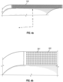
- the annular beam is further illustrated in Figures 4a and 4b .
- the annular beam is reinforced with a circumferential reinforcement 301.
- the reinforcement comprises 7 layers that are radially spaced.
- the beam comprises an elastomeric matrix material 302, which may comprise rubber.
- the spacing of the radial layers is approximately equal to the reinforcement pace in the axial direction. As such, this reinforcement forms a transversally isotropic composite in the R-Y section of the annular beam. If the cord to cord spacing in the radial direction is within +/-33% of the cord to cord spacing in the axial direction, the resulting composite is approximately transversally isotropic.
- the reinforcement may comprise steel cable or any suitable high stiffness and high strength material.
- the reinforcement comprises a continuously pultruded glass monofilament. The inventors have found this type of reinforcement may be particularly advantageous.
- Figure 5 is a structural 2D FEA of a molding simulation to predict deflections in the annular beam and tread.
- stiffnesses are represented on a unit width basis. Calculation of the reinforcement stiffness is therefore normalized with respect to a section that is 1 mm thick in the axial direction.
- molten elastomer is injected into a mold, into which an annular beam has been positioned.
- the annular beam is positioned such that radially inward surface 201 functions as an outer radial extent of a mold cavity.
- the molding operation then forms at least a portion of the annular support 103, and at least a portion of the rim 104.
- the hub 105 may also be positioned in the same mold, and the molding operation may overmold the thermoplastic elastomer around the hub.
- the annular beam comprises circumferential reinforcement 301 and matrix material 302.
- Tread 101 contacts a rigid mold surface 400 on the outer radial extents 305 of the tread pattern.
- Tread groove walls 303 may be free to deform.
- the outer radial extent of the tread is constrained in the radial direction, but the tread may be free to compress. In other words, the presence of a tread pattern may create air voids between the tread and the mold surface 400. Therefore, the rigidity of the annular beam in the circumferential direction becomes very important.
- the reinforcements develop tension force T. This is necessary because the tread groove walls may deform. Since the tread may comprise rubber, the compressive stiffness of the tread will be small compared to an injection pressure. The blocks will compress and bulge out due to Poisson effects. Stiff reinforcements are necessary to mitigate this undesired effect.
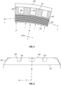
- Figure 6 illustrates an exemplary position of the annular beam and tread in a mold, in an RY section.
- Mold surface 401 is at a lateral extent of the annular beam and tread. This section serves as shut off, preventing molten elastomer from traveling out of the mold cavity and around the annular beam.
- mold surface 400 constrains the outer radial extent 305 of the tread alone.
- mold surfaces 400 and 401 may be smooth and therefore low cost. There does not need to be a supporting structure for tread groove bottom 304, nor tread pattern side 303.
- Figure 7b shows results with reinforcement.
- the deflections are about five times less.
- the inner surface deflection is now 0.50 mm to 0.62 mm. This level of deflection is manageable in a thermoplastic injection process.
- Figure 5 approximates a pressure vessel for the case of a soft tread and high modulus reinforcements.
- well-known equations apply that relate reinforcement tension to internal pressure.
- Further use of basic relationships between modulus, area, and strain can be added to create a relationship between a desired maximum permissible radial deflection and other design parameters. This is given below: P R 2 AE W ⁇ R ⁇
- an injection pressure P 1 MPa (146 psi) is a representative pressure at the inner radius of the beam during a molding process. Further, the inventors have determined that an acceptable value for the radial deflection R ⁇ at the inner radius may be as low as 2 mm. Substituting these in Equation (1): R 2 EA W ⁇ 2 mm 3 N
- an acceptable value may be as low as 2 mm. In some cases, this may be 1.5 mm. In other cases, it may be 1.0 mm, or even lower.
- Equation (2) is provided with units of Newtons and millimeters. Thus, stress is in Mega-Pascals. Other unit systems should be converted to these units, in order to apply Equation (2).
- the annular beam deflection at inner radius under injection pressure may also be directly measured using the following procedure:
- EA 3.2E+07 N.
- R ⁇ 0.7 mm.
- Figure 8a shows an NPT having 2 layers of glass monofilament reinforcement in the annular beam. The layers are separated by a layer of isotropic rubber. The NPT is loaded against a surface of reverse curvature, with a radius equal to that of the NPT. At 14,500 N, the reinforcement layer on the outer radial extent of the annular beam buckles. It becomes unstable. This may lead to failure - either in the rubber matrix or the reinforcement itself.
- Figure 8b shows an NPT having 3 layers of reinforcement. Now, there are 2 adjacent layers at the outer radial extent of the annular beam. At a load of 17,000 N, the structure remains stable.
- the "critical load” is the load at which cord buckling begins to occur.
- Critical load is shown relative to the number of reinforcement layers in Figure 9 .
- a critical load of 27,500 N is predicted. This represents a doubling of the performance of 2 layers.
- the mechanism for this improvement may relate to the creation of a reinforced annular beam that is transversally isotropic.
- cord-rubber composite may behave like a classical composite of high modulus resin and fibers. Excellent prototype performance in testing, as well as these modeling results, show this is indeed the case.
- the inventors have found that performance is best when the cord to cord distance in the radial direction is within 33% of the cord to cord distance in the axial direction. In some cases, this may need to be 25%, and in some cases, 10%, and in some cases even less.
- a critical buckling stress, per Equation (3) of at least 5 MPa is needed; in some cases, at least 8 MPa, and in other cases, even higher.
- the required cord volume fraction may be at least 0.15; in other cases, 0.25; in other cases, 0.35, and in other cases, even higher.
- a rubber matrix shear modulus may be at least 3 MPa, in some cases 5 MPa, and in some cases even higher.
- the outer radial reinforcement layers sustain high compressive stress, even without consideration of macroscopic buckling. As such, the cords themselves need to have high compressive strength.
- the journal paper discloses a method of measuring compressive strength of a single cord or cable reinforcement. Using that methodology, a continuously pultruded glass monofilament may have a compressive strength of 1.1 GPa.
- the inventors have found that an exemplary NPT benefits from a reinforcement having a compressive strength of at least 0.5 MPa; in other cases, 0.8 MPa; and in the most severe use, more than 1.1 GPa. Compressive strength of any cord or cable can be measured using the same procedure described in the journal paper.
- FIG 10 is an exemplary NPT.
- the annular support comprises thermoplastic elastomer spokes 103 that extend in the radial direction which do not intersect other ones of the spokes.
- the outer radial extent is adhered to the inner radial extent 201 of the annular beam.
- a uniform thickness 401 of thermoplastic elastomer is adhered to the inner radial surface of the annular beam.
- the inner radial extent is adhered to the outer radial extent of the rim portion 104, which may comprise the thermoplastic elastomer.
- the rim may be thicker and more rigid than the spokes. Accordingly, this creates a rigid, fixed-fixed boundary for the spoke.
- Figure 11a shows an R-T cross section of an exemplary NPT as configured in the mold, before de-molding.
- Spoke 103 extends from radially outer extent B (joined to annular beam 102) to radially inner extent A (joined to rim 102).
- the curvilinear distance Lc is the length of the spoke before de-molding.
- the curvilinear distance Lc R ⁇ , with angle ⁇ in radians.
- Distance L is the linear distance between points A and B.
- Figure 11b shows the after-molding geometry of the exemplary NPT of Figure 10a. Due to the circumferential reinforcement of the annular beam 102, using a reinforcement of low CTE, the inner radius of the annular beam R B is relatively unchanged. Similarly, the inner radius R R of rim 104 is relatively unchanged or may even be slightly smaller. An exemplary example of the rim design will be shown in the section below.
- a spoke prestrain S PS of at least 0.5% is needed to give the advantageous load vs. deflection behavior that was earlier disclosed; in some cases, at least 1.0% prestrain is better; in other cases, at least 1.5% is beneficial, and in others, even more.
- the stress-free length will be less. The amount by which it is less, divided by the length before removal, can give the percent pre-strain in the tire.
- Figure 12 shows an exemplary NPT R-Y cross section.
- the rim material 104 may comprise thermoplastic elastomer that is formed in the same operation as the spokes. Further, the hub 105 may have portions 501 that extend in the axial direction. In some cases, the hub may extend 15% over the axial width of the rim; in other cases, the hub may extend 30%; and in other cases, the hub may extent over 50% of the axial width.
- the rim R B may not change during the molding operation. Steel is high modulus and low CTE, which constrains the rim. If the hub extends 15% or less over the axial width of the rim, the rim R B may decrease as the tire cools. Since most of the rim comprises the thermoplastic elastomer, R B decreases due to the high CTE. This can increase the amount of prestrain in the spokes to a greater value than that given in Equation (5).
- This exemplary rim design embodies a hub that is over-molded by the same thermoplastic elastomer used to form the spokes and the rim. It may be low cost, yet quite efficient in providing an anchor for the lower extremity of the spokes.
- spoke pre-strain can be amplified with other design parameters.
- the inventors have found that spoke modulus and spoke thickness may greatly accentuate the positive performances.
- spoke modulus and spoke thickness may greatly accentuate the positive performances.
- thermal shrinkage these were studied with 2D FEA.
- the cumulative effect of these design parameters was surprising.
- the tire size 33x10-15 is commonly used for larger Utility Task Vehicles (UTV). 4 versions shown below were modeled in this size. Each version had identical annular beams. The only differences related to the design parameters in the table below. Version Spoke Prestrain (%) Spoke thickness (mm) Spoke modulus (MPa) V1 0 4 45 V2 1 4 45 V3 1 5 90 V4 1 6 90
- Figure 13 shows deformed geometries of V1 and V2, for which the only difference is spoke prestrain.
- the 1% spoke prestrain obviously results in lower deflection and less spoke deformation at a design load of 4000 N for V2, compared to V1.
- Figure 14 shows version V4 at 4000 N and 7000 N.
- Af 4000 N the deflection is minimal - the spoke deformation is quite small.
- the deflection is less than the reference version V1 at a load of 4000 N.
- spoke pre-strain has not changed from version V2 to V4, spoke pre-tension has been increased.
- Spoke modulus and spoke thickness have been increased, which results in a much higher spoke pretension, as given in Equation (5).
- Figure 15 shows FEA predictions of load vs. deflection for V1, V2, V3, and V4.
- V4 has a deflection of less than 10 mm at a design load of 4000N, whereas the reference version V1 requires 30 mm deflection.
- a tangent KZ at zero deflection may be at least 2 times the tangent KZ at a deflection required to develop a design load. In other cases, this may be at least 3 times; in other cases, this may be 4 times, and in other cases, even more.
- an exemplary NPT may develop a long contact patch, even at a minimal deflection.
- the contact patch length vs. deflection is shown for V1, V2, and V3 in Figure 17 .
- FZ 4000 N.
- V1 develops a contact patch length of 135 mm.
- the contact length divided by the vertical deflection is 4.3.
- V2 requires a deflection of 22 mm and a contact length of 125 mm. This gives a ratio of 5.7.
- V3 requires a deflection of 11 mm and a contact length of 110 mm, for a ratio of 10.0.
- An exemplary NPT may combine low deflection with a long contact patch. As such, low rolling resistance and improved endurance may be combined with high traction performance.
- a ratio of a tire deflection at a design load to a contact patch length at the design load may be as much as 5. In other cases, it may be as much as 7; in other cases it may be as high as 10, and in other cases, even higher.
- Figure 18 shows the deformed geometry of a representative model.
- FEA results agreed very well with Euler's equation. For example, given a spoke length 100 mm, width 200 mm, and modulus 100 MPA: Thickness F C FEA F C Euler Critical 2.5 mm 111 N 102 N 3.5 286 280 4.5 591 594
- spoke buckling load can therefore be used as a design parameter in development of an exemplary NPT that carries load in tension (spokes in tension around the top of the tire, away from the contact area) and spokes in compression (spokes in the contact area). This is one of the effects seen in Figure 14 , in which V4 has spokes with a higher buckling load.
- an exemplary NPT may have spokes that have a critical buckling load of at least 10% of the design load; in other cases, at least 15% of the design load; in other cases, at least 20% of the design load, and in other cases even higher.
- An exemplary NPT may have thermoplastic elastomer comprising at least a portion of the rim. In this case, the elastomer may first form a portion of the rim before forming the annular support.
- MFA Mold Flow Analysis
- method or “process” refers to one or more steps that may be performed in other ordering than shown without departing from the scope of the presently disclosed invention. Any sequence of steps is exemplary and is not intended to limit methods described herein to any particular sequence, nor is it intended to preclude adding steps, omitting steps, repeating steps, or performing steps simultaneously.
Landscapes
- Engineering & Computer Science (AREA)
- Mechanical Engineering (AREA)
- Tires In General (AREA)
- Moulds For Moulding Plastics Or The Like (AREA)
- Tyre Moulding (AREA)
Claims (7)
- Procédé pour former un pneu non pneumatique, le procédé comprenant :l'insertion d'une partie bande de roulement et d'une barre annulaire (102) dans un moule (400, 401), ladite partie bande de roulement comprenant une sculpture de bande de roulement (303) et ladite barre annulaire s'étendant radialement vers l'intérieur à partir de la partie bande de roulement et comprenant un renfort circonférentiel, ledit moule (400, 401) supportant la sculpture de bande de roulement (303) seulement sur une étendue radiale extérieure (305) de la sculpture de bande de roulement ;l'insertion d'une jante (104) s'étendant radialement vers l'intérieur à partir de la barre annulaire ; etla formation d'un support annulaire constitué d'un élastomère thermoplastique s'étendant radialement vers l'intérieur à partir de la barre annulaire.
- Procédé selon la revendication 1, dans lequel le support annulaire est formé par injection thermoplastique.
- Procédé selon la revendication 2, dans lequel le pneu non pneumatique comprend en outre une jante qui s'étend radialement vers l'intérieur à partir du support annulaire.
- Procédé selon la revendication 3, dans lequel le support annulaire comprend des rayons qui s'étendent dans la direction radiale, reliant la barre annulaire à la jante.
- Procédé selon la revendication 4, dans lequel la jante comprend l'élastomère thermoplastique.
- Procédé selon l'une quelconque des revendications 1 à 5, dans lequel une grille d'injection est au niveau d'une étendue radialement vers l'intérieur du support annulaire.
- Procédé selon l'une quelconque des revendications 1 à 6, dans lequel une grille d'injection est au niveau d'une étendue radialement vers l'intérieur de la jante.
Applications Claiming Priority (2)
| Application Number | Priority Date | Filing Date | Title |
|---|---|---|---|
| US202063018496P | 2020-04-30 | 2020-04-30 | |
| PCT/US2021/030317 WO2021222845A1 (fr) | 2020-04-30 | 2021-04-30 | Procédé de formation d'un pneu non pneumatique |
Publications (2)
| Publication Number | Publication Date |
|---|---|
| EP4143016A1 EP4143016A1 (fr) | 2023-03-08 |
| EP4143016B1 true EP4143016B1 (fr) | 2024-11-27 |
Family
ID=76076474
Family Applications (1)
| Application Number | Title | Priority Date | Filing Date |
|---|---|---|---|
| EP21727677.3A Active EP4143016B1 (fr) | 2020-04-30 | 2021-04-30 | Procédé de formation d'un pneu non pneumatique |
Country Status (4)
| Country | Link |
|---|---|
| US (1) | US20230173774A1 (fr) |
| EP (1) | EP4143016B1 (fr) |
| CN (1) | CN115803182B (fr) |
| WO (1) | WO2021222845A1 (fr) |
Families Citing this family (1)
| Publication number | Priority date | Publication date | Assignee | Title |
|---|---|---|---|---|
| US20230173846A1 (en) * | 2020-04-30 | 2023-06-08 | Brooks ADAMS | Non-pneumatic tire |
Family Cites Families (14)
| Publication number | Priority date | Publication date | Assignee | Title |
|---|---|---|---|---|
| US3144160A (en) * | 1961-11-03 | 1964-08-11 | Leon R Lopez | Receptacles with vacuum cell units or the like |
| WO2003018332A1 (fr) * | 2001-08-24 | 2003-03-06 | Societe De Technologie Michelin | Pneu non pneumatique |
| US9662939B2 (en) * | 2009-07-28 | 2017-05-30 | Bridgestone Americas Tire Operations, Llc | Tension-based non-pneumatic tire |
| BR112013017295A2 (pt) | 2011-01-06 | 2016-10-25 | Michelin & Cie | aparelho para moldagem de um pneu não-pneumático |
| US20130276968A1 (en) * | 2012-04-22 | 2013-10-24 | James G. Moore | Process for forming an airless solid core tire mounted onto a wheel |
| EP3007909A4 (fr) | 2013-06-15 | 2017-03-01 | Ronald Thompson | Bague annulaire et bandage non pneumatique |
| FR3015360B1 (fr) * | 2013-12-20 | 2016-01-01 | Michelin & Cie | Jante souple a crochets flottants |
| JP6339855B2 (ja) * | 2014-05-14 | 2018-06-06 | 住友ゴム工業株式会社 | エアレスタイヤ及びその製造方法 |
| CA3006801A1 (fr) * | 2015-12-16 | 2017-06-22 | Jeremie Zuchoski | Roue comprenant un pneu non pneumatique |
| WO2017117587A1 (fr) | 2015-12-31 | 2017-07-06 | Compagnie Generale Des Etablissements Michelin | Bandage non pneumatique |
| US10682886B2 (en) * | 2016-04-13 | 2020-06-16 | The Goodyear Tire & Rubber Company | Non-pneumatic tire |
| US10384409B2 (en) * | 2016-11-15 | 2019-08-20 | The Goodyear Tire & Rubber Company | Method of manufacturing a non-pneumatic support structure |
| WO2018101937A1 (fr) * | 2016-11-30 | 2018-06-07 | Compagnie Generale Des Etablissements Michelin | Bande de cisaillement comportant un caoutchouc à hystérésis ultra-faible |
| WO2019050547A1 (fr) * | 2017-09-11 | 2019-03-14 | Compagnie Generale Des Etablissements Michelin | Rayon pour pneu non pneumatique |
-
2021
- 2021-04-30 EP EP21727677.3A patent/EP4143016B1/fr active Active
- 2021-04-30 WO PCT/US2021/030317 patent/WO2021222845A1/fr not_active Ceased
- 2021-04-30 US US17/997,551 patent/US20230173774A1/en not_active Abandoned
- 2021-04-30 CN CN202180039465.6A patent/CN115803182B/zh active Active
Also Published As
| Publication number | Publication date |
|---|---|
| CN115803182B (zh) | 2026-03-20 |
| WO2021222845A1 (fr) | 2021-11-04 |
| EP4143016A1 (fr) | 2023-03-08 |
| CN115803182A (zh) | 2023-03-14 |
| US20230173774A1 (en) | 2023-06-08 |
Similar Documents
| Publication | Publication Date | Title |
|---|---|---|
| EP4143037B1 (fr) | Pneu non pneumatique | |
| EP4143038B1 (fr) | Roue comprenant un pneu non pneumatique | |
| US11697259B2 (en) | Annular ring and non-pneumatic tire | |
| US11633985B2 (en) | Wheel comprising a non-pneumatic tire | |
| US20210188008A1 (en) | Non-pneumatic tire and other annular devices | |
| CN102245403B (zh) | 改进的轮胎滑水性能 | |
| KR100642040B1 (ko) | 구조적으로 지탱되는 탄성 타이어 | |
| KR100810935B1 (ko) | 무공압 타이어 | |
| RU2372209C2 (ru) | Структурно несущая шина, а также способ определения поперечного профиля перемычки-спицы для такой шины | |
| Bolarinwa et al. | Finite element simulation of the tyre burst test | |
| WO2021222839A1 (fr) | Pneu non pneumatique | |
| EP4143016B1 (fr) | Procédé de formation d'un pneu non pneumatique | |
| JP5290986B2 (ja) | 重量物運搬車両用タイヤ | |
| Nyaaba et al. | FEA Prediction of Off-Road Tire Temperature Distribution |
Legal Events
| Date | Code | Title | Description |
|---|---|---|---|
| STAA | Information on the status of an ep patent application or granted ep patent |
Free format text: STATUS: UNKNOWN |
|
| STAA | Information on the status of an ep patent application or granted ep patent |
Free format text: STATUS: THE INTERNATIONAL PUBLICATION HAS BEEN MADE |
|
| PUAI | Public reference made under article 153(3) epc to a published international application that has entered the european phase |
Free format text: ORIGINAL CODE: 0009012 |
|
| STAA | Information on the status of an ep patent application or granted ep patent |
Free format text: STATUS: REQUEST FOR EXAMINATION WAS MADE |
|
| 17P | Request for examination filed |
Effective date: 20221109 |
|
| AK | Designated contracting states |
Kind code of ref document: A1 Designated state(s): AL AT BE BG CH CY CZ DE DK EE ES FI FR GB GR HR HU IE IS IT LI LT LU LV MC MK MT NL NO PL PT RO RS SE SI SK SM TR |
|
| DAV | Request for validation of the european patent (deleted) | ||
| DAX | Request for extension of the european patent (deleted) | ||
| GRAP | Despatch of communication of intention to grant a patent |
Free format text: ORIGINAL CODE: EPIDOSNIGR1 |
|
| STAA | Information on the status of an ep patent application or granted ep patent |
Free format text: STATUS: GRANT OF PATENT IS INTENDED |
|
| INTG | Intention to grant announced |
Effective date: 20240701 |
|
| GRAS | Grant fee paid |
Free format text: ORIGINAL CODE: EPIDOSNIGR3 |
|
| GRAA | (expected) grant |
Free format text: ORIGINAL CODE: 0009210 |
|
| STAA | Information on the status of an ep patent application or granted ep patent |
Free format text: STATUS: THE PATENT HAS BEEN GRANTED |
|
| AK | Designated contracting states |
Kind code of ref document: B1 Designated state(s): AL AT BE BG CH CY CZ DE DK EE ES FI FR GB GR HR HU IE IS IT LI LT LU LV MC MK MT NL NO PL PT RO RS SE SI SK SM TR |
|
| REG | Reference to a national code |
Ref country code: GB Ref legal event code: FG4D |
|
| REG | Reference to a national code |
Ref country code: CH Ref legal event code: EP |
|
| REG | Reference to a national code |
Ref country code: IE Ref legal event code: FG4D |
|
| REG | Reference to a national code |
Ref country code: DE Ref legal event code: R096 Ref document number: 602021022447 Country of ref document: DE |
|
| REG | Reference to a national code |
Ref country code: LT Ref legal event code: MG9D |
|
| REG | Reference to a national code |
Ref country code: NL Ref legal event code: MP Effective date: 20241127 |
|
| PG25 | Lapsed in a contracting state [announced via postgrant information from national office to epo] |
Ref country code: PT Free format text: LAPSE BECAUSE OF FAILURE TO SUBMIT A TRANSLATION OF THE DESCRIPTION OR TO PAY THE FEE WITHIN THE PRESCRIBED TIME-LIMIT Effective date: 20250327 Ref country code: IS Free format text: LAPSE BECAUSE OF FAILURE TO SUBMIT A TRANSLATION OF THE DESCRIPTION OR TO PAY THE FEE WITHIN THE PRESCRIBED TIME-LIMIT Effective date: 20250327 Ref country code: HR Free format text: LAPSE BECAUSE OF FAILURE TO SUBMIT A TRANSLATION OF THE DESCRIPTION OR TO PAY THE FEE WITHIN THE PRESCRIBED TIME-LIMIT Effective date: 20241127 |
|
| PG25 | Lapsed in a contracting state [announced via postgrant information from national office to epo] |
Ref country code: FI Free format text: LAPSE BECAUSE OF FAILURE TO SUBMIT A TRANSLATION OF THE DESCRIPTION OR TO PAY THE FEE WITHIN THE PRESCRIBED TIME-LIMIT Effective date: 20241127 Ref country code: NL Free format text: LAPSE BECAUSE OF FAILURE TO SUBMIT A TRANSLATION OF THE DESCRIPTION OR TO PAY THE FEE WITHIN THE PRESCRIBED TIME-LIMIT Effective date: 20241127 |
|
| REG | Reference to a national code |
Ref country code: AT Ref legal event code: MK05 Ref document number: 1745341 Country of ref document: AT Kind code of ref document: T Effective date: 20241127 |
|
| PG25 | Lapsed in a contracting state [announced via postgrant information from national office to epo] |
Ref country code: BG Free format text: LAPSE BECAUSE OF FAILURE TO SUBMIT A TRANSLATION OF THE DESCRIPTION OR TO PAY THE FEE WITHIN THE PRESCRIBED TIME-LIMIT Effective date: 20241127 |
|
| PG25 | Lapsed in a contracting state [announced via postgrant information from national office to epo] |
Ref country code: ES Free format text: LAPSE BECAUSE OF FAILURE TO SUBMIT A TRANSLATION OF THE DESCRIPTION OR TO PAY THE FEE WITHIN THE PRESCRIBED TIME-LIMIT Effective date: 20241127 |
|
| PG25 | Lapsed in a contracting state [announced via postgrant information from national office to epo] |
Ref country code: NO Free format text: LAPSE BECAUSE OF FAILURE TO SUBMIT A TRANSLATION OF THE DESCRIPTION OR TO PAY THE FEE WITHIN THE PRESCRIBED TIME-LIMIT Effective date: 20250227 |
|
| PG25 | Lapsed in a contracting state [announced via postgrant information from national office to epo] |
Ref country code: GR Free format text: LAPSE BECAUSE OF FAILURE TO SUBMIT A TRANSLATION OF THE DESCRIPTION OR TO PAY THE FEE WITHIN THE PRESCRIBED TIME-LIMIT Effective date: 20250228 Ref country code: LV Free format text: LAPSE BECAUSE OF FAILURE TO SUBMIT A TRANSLATION OF THE DESCRIPTION OR TO PAY THE FEE WITHIN THE PRESCRIBED TIME-LIMIT Effective date: 20241127 Ref country code: AT Free format text: LAPSE BECAUSE OF FAILURE TO SUBMIT A TRANSLATION OF THE DESCRIPTION OR TO PAY THE FEE WITHIN THE PRESCRIBED TIME-LIMIT Effective date: 20241127 |
|
| PG25 | Lapsed in a contracting state [announced via postgrant information from national office to epo] |
Ref country code: PL Free format text: LAPSE BECAUSE OF FAILURE TO SUBMIT A TRANSLATION OF THE DESCRIPTION OR TO PAY THE FEE WITHIN THE PRESCRIBED TIME-LIMIT Effective date: 20241127 |
|
| PG25 | Lapsed in a contracting state [announced via postgrant information from national office to epo] |
Ref country code: RS Free format text: LAPSE BECAUSE OF FAILURE TO SUBMIT A TRANSLATION OF THE DESCRIPTION OR TO PAY THE FEE WITHIN THE PRESCRIBED TIME-LIMIT Effective date: 20250227 |
|
| PG25 | Lapsed in a contracting state [announced via postgrant information from national office to epo] |
Ref country code: SM Free format text: LAPSE BECAUSE OF FAILURE TO SUBMIT A TRANSLATION OF THE DESCRIPTION OR TO PAY THE FEE WITHIN THE PRESCRIBED TIME-LIMIT Effective date: 20241127 |
|
| PGFP | Annual fee paid to national office [announced via postgrant information from national office to epo] |
Ref country code: DE Payment date: 20250422 Year of fee payment: 5 |
|
| PG25 | Lapsed in a contracting state [announced via postgrant information from national office to epo] |
Ref country code: DK Free format text: LAPSE BECAUSE OF FAILURE TO SUBMIT A TRANSLATION OF THE DESCRIPTION OR TO PAY THE FEE WITHIN THE PRESCRIBED TIME-LIMIT Effective date: 20241127 |
|
| PG25 | Lapsed in a contracting state [announced via postgrant information from national office to epo] |
Ref country code: EE Free format text: LAPSE BECAUSE OF FAILURE TO SUBMIT A TRANSLATION OF THE DESCRIPTION OR TO PAY THE FEE WITHIN THE PRESCRIBED TIME-LIMIT Effective date: 20241127 |
|
| PGFP | Annual fee paid to national office [announced via postgrant information from national office to epo] |
Ref country code: FR Payment date: 20250425 Year of fee payment: 5 |
|
| PG25 | Lapsed in a contracting state [announced via postgrant information from national office to epo] |
Ref country code: RO Free format text: LAPSE BECAUSE OF FAILURE TO SUBMIT A TRANSLATION OF THE DESCRIPTION OR TO PAY THE FEE WITHIN THE PRESCRIBED TIME-LIMIT Effective date: 20241127 |
|
| PG25 | Lapsed in a contracting state [announced via postgrant information from national office to epo] |
Ref country code: SK Free format text: LAPSE BECAUSE OF FAILURE TO SUBMIT A TRANSLATION OF THE DESCRIPTION OR TO PAY THE FEE WITHIN THE PRESCRIBED TIME-LIMIT Effective date: 20241127 |
|
| PG25 | Lapsed in a contracting state [announced via postgrant information from national office to epo] |
Ref country code: CZ Free format text: LAPSE BECAUSE OF FAILURE TO SUBMIT A TRANSLATION OF THE DESCRIPTION OR TO PAY THE FEE WITHIN THE PRESCRIBED TIME-LIMIT Effective date: 20241127 |
|
| PG25 | Lapsed in a contracting state [announced via postgrant information from national office to epo] |
Ref country code: IT Free format text: LAPSE BECAUSE OF FAILURE TO SUBMIT A TRANSLATION OF THE DESCRIPTION OR TO PAY THE FEE WITHIN THE PRESCRIBED TIME-LIMIT Effective date: 20241127 |
|
| REG | Reference to a national code |
Ref country code: DE Ref legal event code: R097 Ref document number: 602021022447 Country of ref document: DE |
|
| PG25 | Lapsed in a contracting state [announced via postgrant information from national office to epo] |
Ref country code: SE Free format text: LAPSE BECAUSE OF FAILURE TO SUBMIT A TRANSLATION OF THE DESCRIPTION OR TO PAY THE FEE WITHIN THE PRESCRIBED TIME-LIMIT Effective date: 20241127 |
|
| PLBE | No opposition filed within time limit |
Free format text: ORIGINAL CODE: 0009261 |
|
| STAA | Information on the status of an ep patent application or granted ep patent |
Free format text: STATUS: NO OPPOSITION FILED WITHIN TIME LIMIT |
|
| REG | Reference to a national code |
Ref country code: CH Ref legal event code: L10 Free format text: ST27 STATUS EVENT CODE: U-0-0-L10-L00 (AS PROVIDED BY THE NATIONAL OFFICE) Effective date: 20251008 |
|
| 26N | No opposition filed |
Effective date: 20250828 |
|
| REG | Reference to a national code |
Ref country code: CH Ref legal event code: H13 Free format text: ST27 STATUS EVENT CODE: U-0-0-H10-H13 (AS PROVIDED BY THE NATIONAL OFFICE) Effective date: 20251125 |
|
| PG25 | Lapsed in a contracting state [announced via postgrant information from national office to epo] |
Ref country code: LU Free format text: LAPSE BECAUSE OF NON-PAYMENT OF DUE FEES Effective date: 20250430 |
|
| PG25 | Lapsed in a contracting state [announced via postgrant information from national office to epo] |
Ref country code: MC Free format text: LAPSE BECAUSE OF FAILURE TO SUBMIT A TRANSLATION OF THE DESCRIPTION OR TO PAY THE FEE WITHIN THE PRESCRIBED TIME-LIMIT Effective date: 20241127 |
|
| GBPC | Gb: european patent ceased through non-payment of renewal fee |
Effective date: 20250430 |
|
| REG | Reference to a national code |
Ref country code: BE Ref legal event code: MM Effective date: 20250430 |
|
| PG25 | Lapsed in a contracting state [announced via postgrant information from national office to epo] |
Ref country code: GB Free format text: LAPSE BECAUSE OF NON-PAYMENT OF DUE FEES Effective date: 20250430 |
|
| PG25 | Lapsed in a contracting state [announced via postgrant information from national office to epo] |
Ref country code: BE Free format text: LAPSE BECAUSE OF NON-PAYMENT OF DUE FEES Effective date: 20250430 |
|
| PG25 | Lapsed in a contracting state [announced via postgrant information from national office to epo] |
Ref country code: CH Free format text: LAPSE BECAUSE OF NON-PAYMENT OF DUE FEES Effective date: 20250430 |
|
| PG25 | Lapsed in a contracting state [announced via postgrant information from national office to epo] |
Ref country code: IE Free format text: LAPSE BECAUSE OF NON-PAYMENT OF DUE FEES Effective date: 20250430 |