EP4143081B1 - Procédé et appareil pour installer un batardeau, par exemple contre la coque d'un navire - Google Patents
Procédé et appareil pour installer un batardeau, par exemple contre la coque d'un navire Download PDFInfo
- Publication number
- EP4143081B1 EP4143081B1 EP20724919.4A EP20724919A EP4143081B1 EP 4143081 B1 EP4143081 B1 EP 4143081B1 EP 20724919 A EP20724919 A EP 20724919A EP 4143081 B1 EP4143081 B1 EP 4143081B1
- Authority
- EP
- European Patent Office
- Prior art keywords
- line
- wall
- cofferdam
- opening
- aperture
- Prior art date
- Legal status (The legal status is an assumption and is not a legal conclusion. Google has not performed a legal analysis and makes no representation as to the accuracy of the status listed.)
- Active
Links
Images








Classifications
-
- B—PERFORMING OPERATIONS; TRANSPORTING
- B63—SHIPS OR OTHER WATERBORNE VESSELS; RELATED EQUIPMENT
- B63B—SHIPS OR OTHER WATERBORNE VESSELS; EQUIPMENT FOR SHIPPING
- B63B17/00—Vessels parts, details, or accessories, not otherwise provided for
- B63B17/0018—Arrangements or devices specially adapted for facilitating access to underwater elements, e.g. to propellers ; Externally attached cofferdams or the like
-
- B—PERFORMING OPERATIONS; TRANSPORTING
- B63—SHIPS OR OTHER WATERBORNE VESSELS; RELATED EQUIPMENT
- B63B—SHIPS OR OTHER WATERBORNE VESSELS; EQUIPMENT FOR SHIPPING
- B63B81/00—Repairing or maintaining vessels
Definitions
- This invention relates to cofferdams for use in forming a temporary dry cavity against a submerged wall, such as a ship's hull, and in particular to methods for installing the cofferdam in its use position.
- a cofferdam means an enclosure with an open part configured to sealingly engage a submerged wall so as to define a cavity between the enclosure and the wall.
- Such cofferdams may be used for example to repair a damaged region on the hull of a ship without the need for dry docking.
- a diver In a typical procedure, a diver is sent down to weld threaded studs onto the hull plating and then to attach the cofferdam to the bolts. The stud bolts are removed by the diver on completion of the repair. In some cases the cofferdam is welded directly to the external hull plating by a diver. However, underwater welding can cause localised cracking of the hull due to the rapid cooling of the weld.
- the present invention provides in various aspects, an apparatus and a method for installing a cofferdam on a wet side of a submerged wall of a structure, and an installation including the structure and the apparatus, as defined in the claims.
- the apparatus includes a connection body defining an aperture, which is sealingly fixed to the dry side of the submerged wall to surround an opening formed through the wall in fluid communication with the aperture.
- the apparatus further includes a flexible line, and a line puller which is mounted in an interior space of the structure and operated to retract the line through the opening and the aperture.
- a line puller pressure barrier is sealingly connected to the connection body to prevent water from flowing through the opening and the aperture into the interior space during operation of the line puller.
- the line is connected to the cofferdam to pull the cofferdam against the wet side of the wall when the line is retracted. After sealingly engaging the cofferdam against the wet side of the wall, water is removed from the temporary cavity defined between the cofferdam and the wall.
- a pressure barrier is sealing connected to the connection body to prevent water from flowing through the opening and the aperture into the interior space while forming the opening.
- connection body By carefully positioning the connection body, optionally two or more such connection bodies on the dry side of the wall, each in a position corresponding to the point of attachment of the respective line to the cofferdam, the cofferdam may easily be guided to the correct position and then urged against the hull to form a seal, working from inside the ship or other structure.
- each line may be connected to an alignment pin which extends from the cofferdam and is received in the respective opening and aperture to further ensure that the cofferdam is located and retained in the desired position.
- the apparatus includes at least one connection body 10 defining an aperture 12, and at least one line puller 20 which, as shown, may be formed as a winch assembly.
- the or each line puller is provided with a respective line puller pressure barrier 21, which, as illustrated, may form a casing of the line puller or winch assembly.
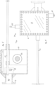
- the apparatus further includes a cofferdam 110 and at least one flexible line 50; each line connects the cofferdam to a respective line puller, as illustrated in Fig. 13 .
- the apparatus further includes, for each connection body 10, a respective valve 60 which is operable to selectively open and close a valve orifice 61, e.g. by translating, rotating or otherwise moving a valve element 62 which is received in the valve body 63.
- the valve orifice 61 is sealingly connected in fluid communication with the opening 7 via the flowpath 11 of the connection body 10.
- the valve may be configured as a gate valve, with the valve element configured as a sliding gate in the valve body.
- the valve 60 is connected sealingly to the connection body 10 and serves to connect the line puller, e.g. winch assembly 20 to the connection body 10.
- the valve 60 may be sealingly and releasably connected to the connection body, e.g. via bolted flanges as shown, or by any other suitable fixing arrangement as known in the art.
- the apparatus may be provided in the form of a kit of parts, optionally including various further components such as a penetrator tool 70 and/or a plug deployment tool 80, which may be connected to the connection body 10, preferably interchangeably, and preferably via the valve 60 - which is to say, the valve 60 is preferably interposed between the connection body 10 and the penetrator tool or plug deployment tool.
- a respective plug 90 and/or cap 100 may be sealingly engagable with each respective connection body 10 to exclude water from the connection body, which may thus form a permanent installation after completing the repair and removing the cofferdam.
- the plug and/or cap may be releasable so that the connection body can be used again with the rest of the apparatus for a future repair.
- connection body 10 defines a flowpath 11 which opens through apertures 12 and 13 at opposite, outer and inner ends of the connection body.
- the outer end is meant that end of the connection body that is connected in use to the submerged wall 2 of the structure 1.
- connection body 10 may be internally threaded 16, e.g. at the inner end aperture 13 as shown, to receive an externally threaded plug 90, and may include a generally cylindrical wall 14 that surrounds the flowpath 11.
- a flange 15 may be formed at the inner end of the wall 14 for connecting components of the apparatus to the connection body 10.
- Such components may include a cap 100 which is bolted to the flange; alternatively or additionally, the inner end of the wall 14 could be externally threaded to receive an internally threaded cap.
- connection body and various optional components of the apparatus may be generally as taught in WO2015/079199 A1 to the present applicant.
- the structure 1 may be a floating structure such as a ship which is supported in a body of water 3, e.g. the sea.
- the submerged wall 2 may form the hull of the ship, and excludes the body of water 3 on the wet side 5 of the wall from the interior space 4 within the structure.
- the interior space 4 is bounded by a dry side 6 of the wall opposite its wet side 5.
- each connection body 10 is fixed sealingly to the dry side 6 of the wall 2 in the desired use position to form an installation.
- the installation may include two or more connection bodies 10 which are sealingly fixed in spaced relation to the dry side 6 of the wall 2 for use with two or more respective line pullers 20 as further explained below.
- the or each connection body 10 may be made from steel or other metal and may be permanently connected, e.g. welded to the wall 2, which may be made from steel plate. Other means of connection may be employed, for example, brazing or mechanical fastening.
- connection body 10 After fixing each connection body 10, it may be tested for pressure tightness, for example, as described in WO2015/079199 A1 . A valve 60 may then be connected to the connection body 10 ( Fig. 7 ).
- the penetrator tool 70 includes a cutter 71 mounted on a tool body 72 which is sealingly and releasably connected to the valve 60, e.g. via a bolted flange as shown.
- the tool 70 is operable in the use position of the connection body to advance and retract the cutter 71 through the open valve orifice 61 and the flowpath 11 and aperture 12 of the connection body 10.
- the cutter 71 may be mounted on a driveshaft 73 that can be engaged by a drive tool 74 to drive the cutter in rotation.
- the driveshaft 73 may be rotatably mounted in an axially movable outer shaft 75 which is rotated by a handle 76 to advance the cutter 71 as it rotates.
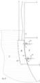
- the cutter 71 After advancing the cutter 71 to engage the wall 2 the cutter 71 is operated (driven in rotation and progressively further advanced) within the connection body 10 to cut an opening 7 through the wall 2, as shown in Fig. 8 .
- the detached coupon may be captured and retracted with the cutter.
- the opening 7 is formed within the aperture 12 of the connection body so that it is surrounded by the connection body 10. That is to say, the opening 7 is in fluid communication with the aperture 12 and flowpath 11 so that it opens into the connection body 10 at the aperture 12, and forms a flowpath opening through, and extending between, the wet and dry sides of the wall 2.
- connection body is in fluid communication with the body of water 3 via the opening 7 and aperture 12, while the connection body 10 by its sealing connection to the wall 2 retains the fluid pressure of the water within the flowpath 11.
- the penetrator tool 70 further includes a pressure barrier, which as shown may be formed by the tool body 72 which sealingly engages the shaft assembly 73, 74.
- the pressure barrier is sealing connected in use to the connection body 10, preferably via the valve 60, and is configured to prevent water from flowing from the body of water 3, through the opening 7 and the aperture 12 into the interior space 4 during operation of the penetrator tool to form the opening 7.
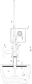
- the cutter 71 is withdrawn on the shaft assembly 73, 74 and then the valve 60 is closed to retain the fluid pressure of the body of water 3 before removing the penetrator tool 70 from the valve 60 ( Fig. 9 ).
- each connection body 10 thus surrounds a respective opening 7 formed through the wall 2 in fluid communication with the respective aperture 12, so that by providing two or more connection bodies 10, two or more line pullers 20 can be mounted in the interior space 4.
- the apparatus further includes a cofferdam 110 which is sealingly engagable in use against the wet side 5 of the submerged wall 2 to define, and exclude water from, a temporary cavity 111 between the cofferdam 110 and the wet side 5 of the wall.
- a cofferdam 110 which is sealingly engagable in use against the wet side 5 of the submerged wall 2 to define, and exclude water from, a temporary cavity 111 between the cofferdam 110 and the wet side 5 of the wall.
- the cofferdam 110 defines an enclosure with an open side 112 surrounded by a sealing surface 113 that engages the wall 2 in use.
- the sealing surface may comprise a resilient sealing material, e.g. rubber.
- the enclosure is configured to resist external fluid pressure when drained of water so that the dry cavity 111 provides a working space within which the wet side 5 of the wall is exposed so that damage to the wall 2 can be repaired.
- the cofferdam 110 may be supported buoyantly or via a cable 114 while it is pulled and/or lowered into position in the body of water 3 alongside the structure 1.
- a hose 115 may be provided for extracting water from the cavity 111 or re-filling the cavity 111 with water after the work is finished.
- the sealing surface 113 may be formed on an assembly of two bodies of resilient sealing material (e.g. elastomer, e.g. rubber or neoprene) of different hardnesses. It is found that a particularly effective seal may be obtained by arranging a relatively harder one of the bodies between the wall of the cofferdam and the softer one of the bodies, so that the softer one of the bodies forms the sealing surface 113 which engages the hull of the ship or other structure.
- the two bodies may be assembled together by adhesive.
- One or more alignment pins 116 may extend from the cofferdam.
- a distal end of each alignment pin 116 is attached or attachable to a distal end of a respective flexible line 50.
- This connection could be provided by a connector at the distal end of the alignment pin, which could be a solid pin; alternatively for example, if the alignment pin is tubular, then the connection to the distal end could be accomplished by passing the distal end (i.e. the distal end portion) of the line 50 through the tublar alignment pin and then connecting the line to the cofferdam inwardly of the pin 116.
- Each pin 116 may be rigidly fixed to the cofferdam 110. Where as shown more than one pin 116 is provided, the pins 116 may extend in parallel relation.
- Each alignment pin 116 may extend outwardly away from the open side 112 of the cofferdam 110, beyond a plane (which may be flat or curved, e.g. as shown) in which the sealing surface 113 lies.
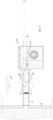
- the plane is defined by the wet side 5 of the wall 2 in the use position of the cofferdam 110; in use, each pin 116 may thus extend through a respective opening 7 and into the aperture 12 and flowpath 11 of the respective connection body 10 as shown in Figs. 14 and 15 and further described below.
- Each alignment pin 116 may be connected to the cofferdam 110 within the cavity 111 so that it extends outwardly through the opening or open side 112 of the cofferdam. In this configuration, the flowpath 11 of each connection body 10 will communicate in use with the cavity 111. Alternatively or additionally, one or more alignment pins 116 could be arranged around the cofferdam outside the cavity 111, each to be received in a connection body 10 which remains in fluid communication with the body of water 3 outside the cavity 111 in the use position of the cofferdam.
- each line puller pressure barrier 21 is sealingly, and preferably releasably connected in use to a respective one of the connection bodies 10, preferably via the respective valve 60.
- Each line puller 20 is mounted in the interior space 4, which may be accomplished by supporting the line puller 20 on the respective line puller pressure barrier 21 which in turn is mounted on the connection body 10, preferably via the valve 60.
- valve orifice 61 can then be opened so that the line 50 can be passed through the opening 7 and the aperture 12 and through the valve orifice 61 to connect the cofferdam 110 to the line puller 20.
- the line puller 20 can then be operated to retract the line through the opening 7 and the aperture 12 via the valve orifice 61.
- the line puller pressure barrier retains (withstands) fluid pressure from the body of water 3 outside the structure to prevent water from flowing through the opening 7 and the aperture 12 into the interior space 4 during operation of the respective line puller 20.
- each line 50 extends from the respective line puller 20 to the cofferdam 110, through a respective opening 7, through the flowpath 11 and apertures 12, 13 of the respective one of the connection bodies 10, and (where a valve 60 is provided) also through the open valve orifice 61.
- the distal end of the line 50 is connected to the cofferdam 110, optionally at the distal end of the respective alignment pin 116 as shown. Where two or more line pullers are used, their respective lines 50 are connected at respective, spaced locations on the cofferdam 110 corresponding to the positions of the respective connection bodies 10 on the wall 2.
- the connection bodies may be spaced apart vertically and/or horizontally so as to accurately locate the cofferdam 110 in its use position.
- Each line puller 20 is operated in its use position to retract the respective line 50 through the respective opening 7 and the aperture 12 to pull the cofferdam towards and against the wet side 5 of the wall 2, as shown in Figs. 13 and 14 .
- the pulling force of the lines 50 sealingly engages the cofferdam 110 against the wet side 5 of the wall 2 to define, and exclude water from, the temporary cavity 111 between the cofferdam 110 and the wet side 5 of the wall 2.
- the water can be removed from the temporary cavity 111 to leave it dry as shown in Fig. 14 .
- the water may be drained from the cavity 111 via a respective one of the connection bodies 10 (e.g. via valve 60) or extracted through the hose 115.
- a limited volume of water e.g. a few litres per hour
- the damaged region of the wall 2 e.g. the ship's hull
- the damaged region of the wall 2 can be cut out to provide an opening through which a worker can access the cavity 111 from inside the structure 1 to work on the wet side 5 of the wall 2.
- the external cut edges formed during installation of the pressure ports can then be made good and the damaged area of the hull prepared for the repair.
- the repair plate can be inserted into the aperture and welded into place from inside the interior space 4 of the structure, e.g. inside the ship.
- the cavity 111 could be accessed from outside the structure 1, e.g. via an external access passage, as known in the art.
- the line puller 20 may include a spool 22 on which the line 50 is stored when retracted.
- the spool 22 including the retracted line may be enclosed within the line puller pressure barrier 21.
- the line puller 20 may be configured as shown as a winch assembly 20 wherein the spool 22 is configured as a winch drum and the line puller pressure barrier 21 forms the pressure tight, outer casing of the assembly.
- the outer casing may include a connection flange 33 to form a pressure tight, bolted connection to the valve 60 as shown.
- the line puller pressure barrier 21 may include a transparent window 23 for observing the operation of the line puller 20.
- fluid pressure from the body of water 3 will cause a quantity of water 8 to flow through the opening 7, connection body 10 and valve 60 into the outer casing after the valve 60 is opened, until the outer casing is full; thus, once the cofferdam 110 is in position, the window 23 may be used to check when the cavity 111 has been emptied of water.
- the spool 22 may be configured to be driven in rotation mechanically from outside the line puller pressure barrier 21, e.g. by a manual crank handle 24 via a driveshaft 25 and geartrain 26 as shown.
- the driveshaft 25 passes through a pressure seal 27 where it enters the outer casing.
- the line puller 20 may include a guide mechanism 28 for guiding the line 50 in an axial direction of the spool 22 during rotation of the spool.
- the guide mechanism 28 may be operable mechanically from outside the line puller pressure barrier 21, e.g. by a rotating shaft 29 which passes through a pressure seal 30 where it enters the casing.
- the shaft 29 may rotate a leadscrew 31 which in turn drives a captive guide block 32 axially along the spool.
- the line 50 passes through the guide block so that by moving the guide block as the spool rotates, the line 50 can be wound evenly onto the spool.
- the line puller 20 may include a float 40 and a float deployment mechanism, which may be configured as an axially displaceable rod 41.
- the float 40 is preferably arranged to fit within and move slidingly along inside the flowpath defined by the axially connected opening 7, connection body 10, valve orifice 61 and line puller pressure barrier 21; the line puller pressure barrier may include a float cavity 42 within which the float 40 is received as shown in Fig. 11 before deployment.
- the float 40 is attached to a distal end (i.e. distal end portion) of the line 50.
- the float 40 may be formed in two halves which are fixed together to enclose the line 50 in-between them before connecting the line puller 20 and the line puller pressure barrier 21 in their use position.
- the float deployment mechanism is then operated, e.g. by pushing in the rod 41 as shown in Fig. 12 , to advance the float 40 and the distal end of the line 50 from the interior space 4, through the opening 7 and the flowpath 11 and apertures 12, 13 of the connection body 10, and via the valve orifice 61 if provided, into the body of water 3 on the wet side 5 of the wall 2.
- the float 40 may be captured and brought to the surface, e.g. by an underwater, remotely operated vehicle (ROV).
- ROV remotely operated vehicle
- the float 40 could be configured to draw the line buoyantly to the surface as the line 50 is payed out by operation of the line puller.
- the line 50 could include a lighter, lead line (i.e. leading line) which is connected to the distal end of the main line, which in turn will be connected to the cofferdam 110 after the float is recovered at the surface of the body of water 3 and the main line drawn up after the lead line.
- the main line could be a steel cable or could be made from lighter fibres, in which case a lead line may not be required.
- the line puller pressure barrier 21 is configured to prevent water from flowing through the opening 7 and the aperture 12, via the connection body 10 into the interior space 4 during operation of the float deployment mechanism.
- each line 50 is retracted to pull the alignment pin 116 into the corresponding opening 7 and the aperture 12.
- each alignment pin 116 is thus received in the respective opening 7 and the aperture 12, within the flowpath 11 of the connection body 10, to locate the cofferdam 110 on the wet side 5 of the wall 2.
- the line puller 20, e.g. spool or winch mechanism, may be locked to retain the alignment pin 116 while the cofferdam is in use.
- the openings 7 provide predefined locations for the attachment points of the lines 50, so that by arranging the connection bodies 10 in a pattern corresponding to the attachment points of the lines 50 to the cofferdam, the cofferdam 110 can be readily located on the wet side of the wall without diver assistance.
- the alignment pins 116 provide a firmer connection which further ensures the correct location of the cofferdam 110 and further resists forces, e.g. a net buoyancy force, that may be applied to the cofferdam in the plane of the wall 2.
- the cofferdam may be released from the wet side 5 of the wall 2, e.g. by unlocking the line puller 20 and paying out the line 50.
- the float deployment mechanism may be adapted to be operable to urge the alignment pins 116 out of the openings 7.
- the cofferdam 110 can the be recovered to surface, e.g. on the cable 114, before detaching the line 50 from the cofferdam ( Fig. 17 ).
- the line 50 is then removed from the opening 7, the flowpath 11 and apertures 12, 13 of the connection body, and the valve orifice 61, optionally by retracting it fully into the line puller 20.
- the valve 60 can then be operated to close the valve orifice 61 before removing the line puller pressure barrier 21 from the valve 60.
- the flowpath 11 and apertures 12, 13 of the connection body 10 can then be sealed with the plug 90.
- the plug deployment tool 80 includes a body 81 which is sealingly and releasably connected to the valve 60 before opening the valve orifice 61 and operating the tool to advance the plug 90 through the valve orifice 61 and to sealingly engage the plug 90 with the connection body 10.
- the plug deployment tool 80 may be generally as described in WO2015/079199 A1 , including an inner shaft 82 which is rotatably received in an outer shaft 85 having a plate 86 with studs 87 which are received in holes 92 in the plug.
- the inner shaft 82 is rotated by a knob 83 to engage a threaded stud 84 in a corresponding threaded hole 91 in the plug 90 to retain the plug 90 in engagement with the studs 87.
- the shaft assembly 82, 85 is pushed axially through the body 81 to engage the threaded plug 90 via the aperture 13 in the flowpath 11 of the connection body 10 before rotating the outer shaft 85 using its handle 88 to screw the plug 90 into the female thread 16 of the connection body 10.
- the plug deployment tool 80 includes a pressure barrier, which conveniently may be formed by the tool body 81 which sealingly retains the shaft assembly 82, 85.
- the pressure barrier is configured to prevent water from flowing through the opening 7 and the flowpath 11 and apertures 12, 13 of the connection body 10, into the interior space 4 during operation of the plug deployment tool 80.
- the plug 90 may include a sacrificial anode 93 which extends into the connection body 10 and/or opening 7 to protect the fixed assembly from corrosion.
- the anode 93 is relatively short as illustrated in Fig. 10 , it could extend through the opening 7 so that an end face of the anode 93 lies in or proximate the plane of the wet side 5 of the wall 2, to provide protection to the cut surfaces of the wall 2 in the opening 7.
- the plug 90 could be engaged in a thread at the outer end of the connection body 10 rather than its inner end as shown.
- valve 60 After sealing each connection body 10 with a respective plug 90, the valve 60 may be removed. A respective cap 100 may then be fixed sealingly to each respective connection body 10 to cover the plug, e.g. by bolting the cap to the flange 15, to provide a safe and compact installation as shown in Fig. 17 .
- a cofferdam 110 is guided and installed against a submerged wall 2 of a structure 1 by one or more flexible lines 50.
- Each line is retracted, via an opening 7 formed in the wall 2, by a line puller 20 mounted inside an interior space 4 of the structure 1 to pull the cofferdam against the wall 2.
- a connection body 10 is sealingly fixed to the dry side 6 of the wall 2 to enclose the opening 7, and a pressure barrier 21 is sealingly connected to the connection body 10 to exclude water from the interior space 4 during operation of the line puller 20.
- the line puller 20 may be configured as a winch assembly with a casing forming the pressure barrier 21.
- connection body could be permanently associated with a valve body for receiving a moving valve element.
- the line puller pressure barrier could be configured other than as a casing of the line puller; for example, it could form a fluid pressure seal through which the line moves slidingly in use.
- the line puller e.g. the spool
- the spool and guide mechanism could be geared together so that they are driven in rotation simultaneously by a common drive mechanism.
- a smooth liner or guide could be provided to extend into the opening 7, to line the whole opening or just the upper part of the opening 7, so as to assist the line 50 to move through the opening without becoming caught on a sharp outer edge of the opening.
- the liner or guide could be advanced from the line puller 20 into the opening 7 and locked in that position, and then subsequently retracted again in a similar way to the rod 41, perhaps after the lead line has been deployed from the spool. It could be arranged behind the float to function as the float deployment mechanism to push the float 40 out through the opening 7 instead of the rod 41.
- the alignment pin 116 could be arranged to pass into the liner or guide or to displace it inwardly as the cofferdam moves into its use position.
- valve 60 to retain fluid pressure while removing or attaching the different components of the apparatus
- the apparatus could be provided as a permanent assembly, or that the opening 7 could be temporarily closed in another way, e.g. by means of a plug inserted from the wet side 5 of the wall 2.
Landscapes
- Chemical & Material Sciences (AREA)
- Engineering & Computer Science (AREA)
- Combustion & Propulsion (AREA)
- Mechanical Engineering (AREA)
- Ocean & Marine Engineering (AREA)
- Other Liquid Machine Or Engine Such As Wave Power Use (AREA)
- Underground Structures, Protecting, Testing And Restoring Foundations (AREA)
Claims (20)
- Appareil pour installer un batardeau (110) sur un côté humide (5) d'une paroi immergée (2) qui élimine une masse d'eau (3) d'un espace intérieur (4) d'une structure (1), l'espace intérieur (4) étant délimité par un côté sec (6) de la paroi (2) opposé au côté humide (5) ; l'appareil comprenant :un batardeau (110), le batardeau pouvant être mis en prise de manière étanche, à l'usage, contre le côté humide (5) de la paroi (2) afin de définir, et éliminer l'eau d'une cavité temporaire (111) entre le batardeau (110) et le côté humide (5) de la paroi (2) ;caractérisé en ce que l'appareil comprend en outre :un corps de raccordement (10) définissant une ouverture (12),le corps de raccordement (10) pouvant être fixé, de manière étanche, au côté sec (6) de la paroi (2) dans une position d'utilisation, pour entourer une ouverture (7) formée à travers la paroi (2) en communication de fluide avec l'ouverture (12) ;une conduite flexible (50) ;un extracteur de conduite (20) pouvant être actionné, lorsqu'il est monté, à l'usage, dans l'espace intérieur (4), pour rétracter la conduite (50) par l'ouverture (7) et l'ouverture (12) dans la position d'utilisation du corps de raccordement (10) ; etune barrière de pression d'extracteur de conduite (21), la barrière de pression d'extracteur de conduite (21) étant raccordée, de manière étanche, à l'usage, au corps de raccordement (10) pour empêcher l'eau de s'écouler par l'ouverture (7) et l'ouverture (12) dans l'espace intérieur (4) pendant le fonctionnement de l'extracteur de conduite (20) ;la conduite (50) étant raccordée, à l'usage, au batardeau (110) pour tirer le batardeau contre le côté humide (5) de la paroi (2), lorsque la conduite (50) est rétractée.
- Appareil selon la revendication 1, comprenant un flotteur (40) et un mécanisme de déploiement de flotteur (41) ;le flotteur (40) étant fixé, à l'usage, à une extrémité distale de la conduite (50) ;le mécanisme de déploiement de flotteur (41) pouvant être actionné, à l'usage, pour faire avancer le flotteur (40) et l'extrémité distale de la conduite (50) de l'espace intérieur (4) par l'ouverture (7) et l'ouverture (12) dans la masse d'eau (3) du côté humide (5) de la paroi (2) ;la barrière de pression d'extracteur de conduite (21) étant configurée pour empêcher l'eau de s'écouler par l'ouverture (7) et l'ouverture (12) dans l'espace intérieur (4) pendant le fonctionnement du mécanisme de déploiement de flotteur (41).
- Appareil selon la revendication 1, comprenant une broche d'alignement (116) s'étendant à partir du batardeau (110) ;la conduite (50) étant raccordée, à l'usage, à une extrémité distale de la broche d'alignement (116) ;la broche d'alignement (116) pouvant être reçue, à l'usage, dans l'ouverture (7) et l'ouverture (12) pour positionner le batardeau (110) sur le côté humide (5) de la paroi (2).
- Appareil selon la revendication 1, dans lequel l'extracteur de conduite (20) comprend une bobine (22) pour stocker la conduite (50), la bobine (22) étant enfermée à l'intérieur de la barrière de pression d'extracteur de conduite (21).
- Appareil selon la revendication 4, dans lequel la barrière de pression d'extracteur de conduite (21) comprend une fenêtre transparente (23) pour observer le fonctionnement de l'extracteur de conduite (20).
- Appareil selon la revendication 4, dans lequel la bobine (22) est configurée pour être entraînée en rotation, par voie mécanique, depuis l'extérieur de la barrière de pression d'extracteur de conduite (21).
- Appareil selon la revendication 6, dans lequel l'extracteur de conduite (20) comprend un mécanisme de guidage (28) pour guider la conduite (50) dans une direction axiale de la bobine (22) pendant la rotation de la bobine, et le mécanisme de guidage (28) peut être actionné, par voie mécanique, depuis l'extérieur de la barrière de pression d'extracteur de conduite (21) .
- Appareil selon la revendication 1, comprenant une valve (60) pouvant être actionnée pour ouvrir et fermer sélectivement un orifice de valve (61) ;la valve (60) pouvant être raccordée de manière étanche et amovible au corps de raccordement (60) ;la barrière de pression d'extracteur de conduite (21) pouvant être raccordée de manière étanche et amovible à la valve (60) ;l'extracteur de conduite (20) pouvant être actionné, à l'usage, pour rétracter la conduite (50) par l'ouverture (7) et l'ouverture (12) via l'orifice de valve (61).
- Appareil selon la revendication 8, comprenant un bouchon (90) et un outil de déploiement de bouchon (80) ;le bouchon (90) pouvant être mis en prise, de manière étanche, dans le corps de raccordement (10) ;l'outil de déploiement de bouchon (80) pouvant être raccordé de manière étanche et amovible à la valve (60) et pouvant fonctionner pour faire avancer le bouchon (90) à travers l'orifice de valve (61) et pour mettre en prise, de manière étanche, le bouchon (90) avec le corps de raccordement (10) ;l'outil de déploiement de bouchon (80) comprenant une barrière de pression (81) configurée pour empêcher l'eau de s'écouler par l'ouverture (7) et l'ouverture (12) dans l'espace intérieur (4) pendant le fonctionnement de l'outil de déploiement de bouchon (80).
- Appareil selon la revendication 8, comprenant un outil de pénétration (70),l'outil de pénétration (70) pouvant être raccordé, de manière étanche et amovible, à la valve (60) ;l'outil de pénétration (70) comprenant un dispositif de coupe (71) et pouvant être actionné, dans la position d'utilisation du corps de raccordement (10), pour faire avancer et rétracter le dispositif de coupe (71) à travers l'orifice de valve (61) et pour actionner le dispositif de coupe (71) pour couper l'ouverture (7) à travers la paroi (2) ;l'outil de pénétration (70) comprenant une barrière de pression (72) configurée pour empêcher l'eau de s'écouler à travers l'ouverture (7) et l'ouverture (12) dans l'espace intérieur (4) pendant le fonctionnement de l'outil de pénétration (70).
- Installation comprenant :une structure (1) définissant un espace intérieur (4) et une paroi immergée (2) qui élimine une masse d'eau (3) de l'espace intérieur (4), l'espace intérieur (4) étant délimité par un côté sec (6) de la paroi ; etun appareil selon la revendication 1, dans laquelle le corps de raccordement (10) est fixé, de manière étanche, sur le côté sec (6) de la paroi, dans la position d'utilisation, pour entourer une ouverture (7) formée à travers la paroi (2) en communication de fluide avec l'ouverture (12).
- Installation selon la revendication 11, comprenant au moins deux desdits corps de raccordement (10) fixés, de manière étanche, en relation espacée, sur le côté sec (6) de la paroi, chacun dans la position d'utilisation, pour entourer une ouverture (7) respective formée à travers la paroi (2) en communication de fluide avec l'ouverture (12) respective, et
au moins deux desdits extracteurs de conduite (20) et les barrières de pression d'extracteur de conduite (21), chaque barrière de pression d'extracteur de conduite (21) étant raccordée, de manière étanche, à un corps respectif des corps de raccordement (10), les extracteurs de conduite (20) pouvant fonctionner pour rétracter les conduites respectives des au moins deux conduites (50) raccordées au batardeau (110) à des emplacements espacés respectifs sur le batardeau (110). - Procédé pour installer un batardeau (110) sur un côté humide (5) d'une paroi immergée (2) qui élimine une masse d'eau (3) d'un espace intérieur (4) d'une structure (1), l'espace intérieur (4) étant délimité par un côté sec (6) de la paroi (2) opposé au côté humide (5) ; le procédé comprenant les étapes consistant à :mettre en prise, de manière étanche, le batardeau (110) contre le côté humide (5) de la paroi (2) afin de définir et d'éliminer l'eau d'une cavité temporaire (111) entre le batardeau (110) et le côté humide (5) de la paroi (2), etretirer l'eau de la cavité temporaire (111) ;et comprenant en outre, avant de mettre en prise, de manière étanche, le batardeau (110) contre le côté humide (5) de la paroi (2), les étapes consistant à :fixer, de manière étanche, un corps de raccordement (10) au côté sec (6) de la paroi (2), et ensuiteformer une ouverture (7) à travers la paroi (2), l'ouverture (7) étant entourée par le corps de raccordement (10) et en communication de fluide avec une ouverture (12) définie dans le corps de raccordement (10),dans lequel une barrière de pression (72) est raccordée, de manière étanche, au corps de raccordement (10) pour empêcher l'eau de s'écouler à travers l'ouverture (7) et l'ouverture (12) dans l'espace intérieur (4) tout en formant l'ouverture (7) ; et comprenant en outre les étapes consistant à :monter un extracteur de conduite (20) dans l'espace intérieur (4) ;raccorder le batardeau (110) à une conduite flexible (50), la conduite (50) s'étendant à travers l'ouverture (7) et l'ouverture (12) vers l'extracteur de conduite (20) ; et ensuiteactionner l'extracteur de conduite (20) pour rétracter la conduite (50) à travers l'ouverture (7) et l'ouverture (12) pour tirer le batardeau (110) contre le côté humide (5) de la paroi (2) ;dans lequel une barrière de pression d'extracteur de conduite (21) est raccordée, de manière étanche, au corps de raccordement (10) pour empêcher l'eau de s'écouler à travers l'ouverture (7) et l'ouverture (12) dans l'espace intérieur (4) pendant le fonctionnement de l'extracteur de conduite (20).
- Procédé selon la revendication 13, comprenant en outre, avant de raccorder le batardeau (110) à la conduite (50), les étapes consistant à :fixer un flotteur (40) à une extrémité distale de la conduite (50), etactionner un mécanisme de déploiement de flotteur (41) pour faire avancer le flotteur (40) et l'extrémité distale de la conduite (50) depuis l'espace intérieur (4) à travers l'ouverture (7) et l'ouverture (12) dans la masse d'eau (3) sur le côté humide (5) de la paroi (2) ;la barrière de pression d'extracteur de conduite (21) étant configurée pour empêcher l'eau de s'écouler à travers l'ouverture (7) et l'ouverture (12) dans l'espace intérieur (4) pendant le fonctionnement du mécanisme de déploiement de flotteur (41).
- Procédé selon la revendication 13, comprenant en outre les étapes consistant à :raccorder la conduite (50) à une extrémité distale d'une broche d'alignement (116) s'étendant à partir du batardeau (110), et ensuiterétracter la conduite (50) pour tirer la broche d'alignement (116) dans l'ouverture (7) et l'ouverture (12) pour positionner le batardeau (110) sur le côté humide (5) de la paroi (2).
- Procédé selon la revendication 13, comprenant en outre les étapes consistant à :raccorder, de manière étanche et amovible, une valve (60) au corps de raccordement (10), la valve (60) étant opérationnelle pour ouvrir et fermer un orifice de valve (61), etraccorder, de manière étanche et amovible, la barrière de pression d'extracteur de conduite (21) à la valve (60) ; et ensuiteouvrir l'orifice de valve (61) et actionner l'extracteur de conduite (20) pour rétracter la conduite (50) à travers l'ouverture (7) et l'ouverture (12) via l'orifice de valve (61).
- Procédé selon la revendication 16, comprenant en outre les étapes consistant à :raccorder, de manière étanche et amovible, un outil de pénétration (70) à la valve (60), etactionner l'outil de pénétration (70) pour faire avancer un dispositif de coupe (71) à travers l'orifice de valve (61) et l'ouverture (12) et pour actionner le dispositif de coupe (71) pour couper l'ouverture (7) à travers la paroi (2).
- Procédé selon la revendication 16, comprenant en outre les étapes consistant à :libérer le batardeau (110) du côté humide (5) de la paroi (2) et retirer la conduite (50) de l'ouverture (7) et de l'ouverture (12) ; et ensuitefermer l'orifice de valve (61) et retirer la barrière de pression d'extracteur de conduite (21) de la valve (60) ; et ensuiteraccorder, de manière étanche et amovible, un outil de déploiement de bouchon (80) à la valve ; et ensuiteouvrir l'orifice de valve (61) et actionner l'outil de déploiement de bouchon (80) pour faire avancer un bouchon (90) à travers l'orifice de valve (61) et pour mettre en prise, de manière étanche, le bouchon (90) avec le corps de raccordement (10).
- Procédé selon la revendication 13, comprenant en outre les étapes consistant à :fixer, de manière étanche, au moins deux desdits corps de raccordement (10) en relation espacée, sur le côté sec (6) de la paroi (2),monter au moins deux desdits extracteurs de conduite (20) dans l'espace intérieur (4) et pour chacun desdits extracteurs de conduite (20), raccorder, de manière étanche, une barrière respective d'au moins deux desdites barrières de pression d'extracteur de conduite (21), à un corps respectif des corps de raccordement (10), etactionner les extracteurs de conduite (20) pour rétracter une conduite respective d'au moins deux conduites (50) raccordées au batardeau (110) à des emplacements espacés respectifs sur le batardeau (110).
- Procédé selon la revendication 19, comprenant en outre l'étape consistant à retirer l'eau de la cavité temporaire (111) via un corps respectif des corps de raccordement (10).
Applications Claiming Priority (1)
| Application Number | Priority Date | Filing Date | Title |
|---|---|---|---|
| PCT/GB2020/051063 WO2021219970A1 (fr) | 2020-04-30 | 2020-04-30 | Procédé et appareil pour installer un batardeau, par exemple contre la coque d'un navire |
Publications (3)
| Publication Number | Publication Date |
|---|---|
| EP4143081A1 EP4143081A1 (fr) | 2023-03-08 |
| EP4143081B1 true EP4143081B1 (fr) | 2024-11-06 |
| EP4143081C0 EP4143081C0 (fr) | 2024-11-06 |
Family
ID=70617154
Family Applications (1)
| Application Number | Title | Priority Date | Filing Date |
|---|---|---|---|
| EP20724919.4A Active EP4143081B1 (fr) | 2020-04-30 | 2020-04-30 | Procédé et appareil pour installer un batardeau, par exemple contre la coque d'un navire |
Country Status (3)
| Country | Link |
|---|---|
| EP (1) | EP4143081B1 (fr) |
| BR (1) | BR112022022022A2 (fr) |
| WO (1) | WO2021219970A1 (fr) |
Families Citing this family (1)
| Publication number | Priority date | Publication date | Assignee | Title |
|---|---|---|---|---|
| WO2021237323A1 (fr) * | 2020-05-28 | 2021-12-02 | Nsg Engenharia, Projetos E Representação Comercial Ltda | Système et procédé pour faire passer un câble à travers la coque d'une unité flottante et installation d'un batardeau portable sans intervention de plongeur |
Family Cites Families (4)
| Publication number | Priority date | Publication date | Assignee | Title |
|---|---|---|---|---|
| US3857249A (en) * | 1973-03-22 | 1974-12-31 | T Kelly | Cofferdam |
| SE435706B (sv) * | 1983-03-04 | 1984-10-15 | Goetaverken Arendal Ab | Anordning for montering av thrusterpropellrar |
| ITMI20130693A1 (it) * | 2013-04-26 | 2014-10-27 | Fincantieri Cantieri Navali It | Metodo per la manutenzione di un propulsore retrattile |
| GB2520688B (en) | 2013-11-27 | 2019-05-01 | E M & I Maritime Ltd | Apparatus and method for inspecting flooded cavities in a floating offshore installation |
-
2020
- 2020-04-30 EP EP20724919.4A patent/EP4143081B1/fr active Active
- 2020-04-30 BR BR112022022022A patent/BR112022022022A2/pt active Search and Examination
- 2020-04-30 WO PCT/GB2020/051063 patent/WO2021219970A1/fr not_active Ceased
Also Published As
| Publication number | Publication date |
|---|---|
| WO2021219970A1 (fr) | 2021-11-04 |
| EP4143081A1 (fr) | 2023-03-08 |
| BR112022022022A2 (pt) | 2022-12-20 |
| EP4143081C0 (fr) | 2024-11-06 |
Similar Documents
| Publication | Publication Date | Title |
|---|---|---|
| US6241424B1 (en) | Method and apparatus for replacing damaged section of a subsea pipeline without loss of product or entry of seawater | |
| FI64097C (fi) | Anordning foer att lyfta upp en pao havsbotten liggande roerledning med tillhjaelp av ett roernedlaeggningsfartyg | |
| DE2344121C2 (de) | Vorrichtung zum Herstellen einer Verbindung eines Rohrabschnittes und Verfahren zum Verbinden von Rohrleitungsabschnitten einer Unterwasserrohrleitung unter Verwendung dieser Vorrichtung | |
| US9644779B2 (en) | Gate valves for installation in pressurized pipes | |
| US6200068B1 (en) | Hot tap fluid blaster apparatus and method of using same | |
| CN104354843B (zh) | 配合rov的海洋油船微型打捞钻孔装置及方法 | |
| US3482410A (en) | Underwater flowline installation | |
| BRPI0715385A2 (pt) | sistema e mÉtodo de perfuraÇço de conduto em carga | |
| EP4143081B1 (fr) | Procédé et appareil pour installer un batardeau, par exemple contre la coque d'un navire | |
| RU2689935C1 (ru) | Мобильный режущий инструмент и способ разрезания подводной трубчатой конструкции | |
| US3602300A (en) | Down-hole installation, recovery, and maintenance tool for wells | |
| CA3146057A1 (fr) | Graisseur de bouchon de retrait de vanne | |
| US4477205A (en) | Apparatus for connecting underwater flow line hubs | |
| US3656501A (en) | Valve-operator assembly with alignment and locking mechanism | |
| OA21104A (en) | Method and apparatus for installing a cofferdam, e.g. against the hull of a ship. | |
| JP3964385B2 (ja) | 不断水式流体制御弁設置工法用フィダー装置 | |
| EP3074305B1 (fr) | Appareil et procédé d'inspection de cavités inondées dans une installation en mer flottante | |
| US4371005A (en) | Protective cover for underwater flow line hub | |
| DE2556276B2 (fr) | ||
| JP2008274614A (ja) | 水中掘進装置及び水中掘進工法 | |
| CN120379894A (zh) | 用于水下钻孔组件的可锁定凸缘 | |
| JP2011001740A (ja) | 水取込装置 | |
| WO2018018668A1 (fr) | Dispositif de projection de fluide de piquage à chaud pour navire sans équipage | |
| BR202024003238U2 (pt) | Ferramenta de corte simultâneo de estojos | |
| JPH06241380A (ja) | 新設管類の接続工法 |
Legal Events
| Date | Code | Title | Description |
|---|---|---|---|
| STAA | Information on the status of an ep patent application or granted ep patent |
Free format text: STATUS: UNKNOWN |
|
| STAA | Information on the status of an ep patent application or granted ep patent |
Free format text: STATUS: THE INTERNATIONAL PUBLICATION HAS BEEN MADE |
|
| PUAI | Public reference made under article 153(3) epc to a published international application that has entered the european phase |
Free format text: ORIGINAL CODE: 0009012 |
|
| STAA | Information on the status of an ep patent application or granted ep patent |
Free format text: STATUS: REQUEST FOR EXAMINATION WAS MADE |
|
| 17P | Request for examination filed |
Effective date: 20221108 |
|
| AK | Designated contracting states |
Kind code of ref document: A1 Designated state(s): AL AT BE BG CH CY CZ DE DK EE ES FI FR GB GR HR HU IE IS IT LI LT LU LV MC MK MT NL NO PL PT RO RS SE SI SK SM TR |
|
| DAV | Request for validation of the european patent (deleted) | ||
| DAX | Request for extension of the european patent (deleted) | ||
| GRAP | Despatch of communication of intention to grant a patent |
Free format text: ORIGINAL CODE: EPIDOSNIGR1 |
|
| STAA | Information on the status of an ep patent application or granted ep patent |
Free format text: STATUS: GRANT OF PATENT IS INTENDED |
|
| INTG | Intention to grant announced |
Effective date: 20240620 |
|
| GRAS | Grant fee paid |
Free format text: ORIGINAL CODE: EPIDOSNIGR3 |
|
| GRAA | (expected) grant |
Free format text: ORIGINAL CODE: 0009210 |
|
| STAA | Information on the status of an ep patent application or granted ep patent |
Free format text: STATUS: THE PATENT HAS BEEN GRANTED |
|
| AK | Designated contracting states |
Kind code of ref document: B1 Designated state(s): AL AT BE BG CH CY CZ DE DK EE ES FI FR GB GR HR HU IE IS IT LI LT LU LV MC MK MT NL NO PL PT RO RS SE SI SK SM TR |
|
| REG | Reference to a national code |
Ref country code: GB Ref legal event code: FG4D |
|
| REG | Reference to a national code |
Ref country code: CH Ref legal event code: EP |
|
| REG | Reference to a national code |
Ref country code: DE Ref legal event code: R096 Ref document number: 602020040799 Country of ref document: DE |
|
| REG | Reference to a national code |
Ref country code: IE Ref legal event code: FG4D |
|
| U01 | Request for unitary effect filed |
Effective date: 20241206 |
|
| U07 | Unitary effect registered |
Designated state(s): AT BE BG DE DK EE FI FR IT LT LU LV MT NL PT RO SE SI Effective date: 20250108 |
|
| PG25 | Lapsed in a contracting state [announced via postgrant information from national office to epo] |
Ref country code: HR Free format text: LAPSE BECAUSE OF FAILURE TO SUBMIT A TRANSLATION OF THE DESCRIPTION OR TO PAY THE FEE WITHIN THE PRESCRIBED TIME-LIMIT Effective date: 20241106 Ref country code: IS Free format text: LAPSE BECAUSE OF FAILURE TO SUBMIT A TRANSLATION OF THE DESCRIPTION OR TO PAY THE FEE WITHIN THE PRESCRIBED TIME-LIMIT Effective date: 20250306 |
|
| PG25 | Lapsed in a contracting state [announced via postgrant information from national office to epo] |
Ref country code: ES Free format text: LAPSE BECAUSE OF FAILURE TO SUBMIT A TRANSLATION OF THE DESCRIPTION OR TO PAY THE FEE WITHIN THE PRESCRIBED TIME-LIMIT Effective date: 20241106 |
|
| PG25 | Lapsed in a contracting state [announced via postgrant information from national office to epo] |
Ref country code: GR Free format text: LAPSE BECAUSE OF FAILURE TO SUBMIT A TRANSLATION OF THE DESCRIPTION OR TO PAY THE FEE WITHIN THE PRESCRIBED TIME-LIMIT Effective date: 20250207 |
|
| PG25 | Lapsed in a contracting state [announced via postgrant information from national office to epo] |
Ref country code: PL Free format text: LAPSE BECAUSE OF FAILURE TO SUBMIT A TRANSLATION OF THE DESCRIPTION OR TO PAY THE FEE WITHIN THE PRESCRIBED TIME-LIMIT Effective date: 20241106 |
|
| PG25 | Lapsed in a contracting state [announced via postgrant information from national office to epo] |
Ref country code: RS Free format text: LAPSE BECAUSE OF FAILURE TO SUBMIT A TRANSLATION OF THE DESCRIPTION OR TO PAY THE FEE WITHIN THE PRESCRIBED TIME-LIMIT Effective date: 20250206 |
|
| PG25 | Lapsed in a contracting state [announced via postgrant information from national office to epo] |
Ref country code: SM Free format text: LAPSE BECAUSE OF FAILURE TO SUBMIT A TRANSLATION OF THE DESCRIPTION OR TO PAY THE FEE WITHIN THE PRESCRIBED TIME-LIMIT Effective date: 20241106 |
|
| PG25 | Lapsed in a contracting state [announced via postgrant information from national office to epo] |
Ref country code: SK Free format text: LAPSE BECAUSE OF FAILURE TO SUBMIT A TRANSLATION OF THE DESCRIPTION OR TO PAY THE FEE WITHIN THE PRESCRIBED TIME-LIMIT Effective date: 20241106 |
|
| PG25 | Lapsed in a contracting state [announced via postgrant information from national office to epo] |
Ref country code: CZ Free format text: LAPSE BECAUSE OF FAILURE TO SUBMIT A TRANSLATION OF THE DESCRIPTION OR TO PAY THE FEE WITHIN THE PRESCRIBED TIME-LIMIT Effective date: 20241106 |
|
| U21 | Renewal fee for the european patent with unitary effect paid with additional fee |
Year of fee payment: 6 Effective date: 20250730 |
|
| PLBE | No opposition filed within time limit |
Free format text: ORIGINAL CODE: 0009261 |
|
| STAA | Information on the status of an ep patent application or granted ep patent |
Free format text: STATUS: NO OPPOSITION FILED WITHIN TIME LIMIT |
|
| PGFP | Annual fee paid to national office [announced via postgrant information from national office to epo] |
Ref country code: MC Payment date: 20250806 Year of fee payment: 6 Ref country code: NO Payment date: 20250818 Year of fee payment: 6 |
|
| 26N | No opposition filed |
Effective date: 20250807 |
|
| PGFP | Annual fee paid to national office [announced via postgrant information from national office to epo] |
Ref country code: GB Payment date: 20250730 Year of fee payment: 6 |
|
| PGFP | Annual fee paid to national office [announced via postgrant information from national office to epo] |
Ref country code: CH Payment date: 20250730 Year of fee payment: 6 |
|
| REG | Reference to a national code |
Ref country code: GB Ref legal event code: 732E Free format text: REGISTERED BETWEEN 20251030 AND 20251105 |
|
| PG25 | Lapsed in a contracting state [announced via postgrant information from national office to epo] |
Ref country code: IE Free format text: LAPSE BECAUSE OF NON-PAYMENT OF DUE FEES Effective date: 20250430 |