EP4144384B1 - Dispositif de diffusion de parfum dans un véhicule - Google Patents
Dispositif de diffusion de parfum dans un véhicule Download PDFInfo
- Publication number
- EP4144384B1 EP4144384B1 EP21194251.1A EP21194251A EP4144384B1 EP 4144384 B1 EP4144384 B1 EP 4144384B1 EP 21194251 A EP21194251 A EP 21194251A EP 4144384 B1 EP4144384 B1 EP 4144384B1
- Authority
- EP
- European Patent Office
- Prior art keywords
- holding
- devices
- coupling
- scenting
- housing
- Prior art date
- Legal status (The legal status is an assumption and is not a legal conclusion. Google has not performed a legal analysis and makes no representation as to the accuracy of the status listed.)
- Active
Links
Images


Classifications
-
- B—PERFORMING OPERATIONS; TRANSPORTING
- B60—VEHICLES IN GENERAL
- B60H—ARRANGEMENTS OF HEATING, COOLING, VENTILATING OR OTHER AIR-TREATING DEVICES SPECIALLY ADAPTED FOR PASSENGER OR GOODS SPACES OF VEHICLES
- B60H3/00—Other air-treating devices
- B60H3/0007—Adding substances other than water to the air, e.g. perfume, oxygen
- B60H3/0014—Adding substances other than water to the air, e.g. perfume, oxygen characterised by the location of the substance adding device
- B60H3/0028—Adding substances other than water to the air, e.g. perfume, oxygen characterised by the location of the substance adding device on or near an air outlet
-
- A—HUMAN NECESSITIES
- A61—MEDICAL OR VETERINARY SCIENCE; HYGIENE
- A61L—METHODS OR APPARATUS FOR STERILISING MATERIALS OR OBJECTS IN GENERAL; DISINFECTION, STERILISATION OR DEODORISATION OF AIR; CHEMICAL ASPECTS OF BANDAGES, DRESSINGS, ABSORBENT PADS OR SURGICAL ARTICLES; MATERIALS FOR BANDAGES, DRESSINGS, ABSORBENT PADS OR SURGICAL ARTICLES
- A61L9/00—Disinfection, sterilisation or deodorisation of air
- A61L9/015—Disinfection, sterilisation or deodorisation of air using gaseous or vaporous substances, e.g. ozone
- A61L9/04—Disinfection, sterilisation or deodorisation of air using gaseous or vaporous substances, e.g. ozone using substances evaporated in the air without heating
- A61L9/12—Apparatus, e.g. holders, therefor
-
- A—HUMAN NECESSITIES
- A61—MEDICAL OR VETERINARY SCIENCE; HYGIENE
- A61L—METHODS OR APPARATUS FOR STERILISING MATERIALS OR OBJECTS IN GENERAL; DISINFECTION, STERILISATION OR DEODORISATION OF AIR; CHEMICAL ASPECTS OF BANDAGES, DRESSINGS, ABSORBENT PADS OR SURGICAL ARTICLES; MATERIALS FOR BANDAGES, DRESSINGS, ABSORBENT PADS OR SURGICAL ARTICLES
- A61L2209/00—Aspects relating to disinfection, sterilisation or deodorisation of air
- A61L2209/10—Apparatus features
- A61L2209/15—Supporting means, e.g. stands, hooks, holes for hanging
Definitions
- the invention relates to a scenting device for a vehicle with a housing and a fragrance container arranged in the housing. Furthermore, the scenting device comprises at least one coupling device which is arranged on the housing and at least one holding device for attaching the scenting device to a ventilation system in the interior of a vehicle.
- scenting devices that can be hung inside the vehicle and, for example, have a material soaked in scent.
- Such devices are inexpensive to manufacture, but their scenting effect can be uneven and the scented body, which is usually hung on the interior rear-view mirror, can obstruct visibility.
- containers with fragrance which are attached to a ventilation grille in the interior of a vehicle.
- the container for the fragrance has inlet openings so that air from the ventilation flows into the container, comes into contact with the fragrance and leaves the container enriched with fragrance molecules through outlet openings.
- Such containers can be attached to the ventilation grille using a clamp and can also be removed from it again.
- US10500299B2 shows a scenting device with a scent stick, which is arranged in a perforated housing.
- DE102011001637A1 shows a scenting device with a container for a fragrance.
- the container can be fixed to a ventilation slot in the interior of a vehicle using a holder.
- the holder is made of elastic material.
- KR20190000337U shows a multifunctional holder with a silicone cap.
- CH709702A2 shows a scenting device for installation in a vehicle. This comprises a scent body which can be mounted with fastening devices on a ventilation grille inside a vehicle.
- the task is to provide a scenting device that can be used in a variety of ways.
- a scenting device for a vehicle having the features of claim 1.
- vehicle includes land vehicles, such as passenger cars and trucks, and also aircraft.
- the scenting device comprises a housing in which a fragrance container is arranged. At least one coupling device is arranged on the housing.
- the scenting device also comprises at least one holding device for attaching the scenting device to a ventilation system in the interior of the vehicle.
- the holding device can be coupled to and decoupled from the coupling device. The holding device can thus be coupled to and decoupled from the housing.
- the option of decoupling the holding device from the housing has the advantage that different types of holding device can be mounted on the housing.
- the fragrance device can therefore be fixed to different ventilation systems, it is flexible and user-friendly.
- worn-out holding devices can also be easily replaced with new holding devices without having to replace the entire fragrance device.
- the scenting device comprises at least two structurally differently designed holding devices, i.e. two different types of holding devices.
- the at least two structurally different holding devices can each be coupled to at least one of the at least one coupling device.
- Every possible holding device can be fixed to every coupling device.
- it can also be designed in such a way that one type of holding device can only be coupled with one or more specific coupling devices, but not with all coupling devices.
- "Different in design" means that the at least two holding devices are not identical, but are designed or shaped differently. In particular, the at least two holding devices adhere to the ventilation in the interior of the vehicle using different technical principles. This makes it possible to attach the scenting device to different types or shapes of ventilation.
- the scenting device can be used flexibly by the user.
- At least three coupling devices can advantageously be arranged on the housing.
- One of the at least one holding device can be coupled to each coupling device.
- the fragrance device can, for example, be mounted on the ventilation with two mounting devices at the same time.
- the three coupling devices are spaced apart from one another and/or inlet openings can be provided between the at least three coupling devices through which air can flow into the housing.
- the coupling device and the holding device are designed in such a way that they couple together in the form of a snap connection.
- a “snap connection” is a connection in which the coupling device and the holding device fit together in a form-fitting manner.
- a snap connection between the holding device and the coupling device appears to be a suitable solution so that the user can easily detach the holding device from the coupling device and couple it to the coupling device.
- the coupling device comprises a frame and the holding device comprises a flat plate, designed such that the plate of the holding device can be pushed under the frame of the coupling device for coupling, in particular wherein the plate has at least one elevation which engages in gaps in the frame in the coupled position.
- one of the at least one holding device has a rubber cap.
- the rubber cap is designed such that it can be clamped between two slats of the ventilation and/or that the rubber cap can be removed from the holding device.
- the rubber cap can comprise silicone, rubber and/or an elastomer, in particular a thermoplastic elastomer, as material.
- elastomer in particular a thermoplastic elastomer
- it can comprise a material with a hardness in the range of 30 Shore-A to 90 Shore-A.
- a rubber cap due to its elasticity, allows the scenting device to be easily mounted on the ventilation in the vehicle.
- the rubber cap is elastic and can adapt to different dimensions of a ventilation system.
- the elasticity also allows the rubber caps to be clamped between two slats of the ventilation system.
- the scenting device advantageously includes at least two holding devices with rubber caps of different sizes.
- the user can therefore choose to mount a larger or smaller rubber cap, depending on the design of the ventilation. If the slats in the fan are further apart from each other, the user couples a holding device with a larger rubber cap to the housing of the scenting device. However, if the slats are less far apart from each other, the user chooses a holding device with a smaller rubber cap. This means that different holding devices with different rubber caps can be supplied with a scenting device, which the user can optionally mount on the housing.
- the rubber cap advantageously comprises a lateral surface, a base surface and an upper surface opposite the base surface.
- the upper surface can be part of the lateral surface.
- the base surface is the surface of the rubber cap which, when mounted, is
- the top side is the surface of the rubber cap which, when mounted, is directed away from the housing of the scenting device.
- a groove is arranged on the upper side of the rubber cap and/or two parallel upper edges are arranged on the upper side of the rubber cap, in particular wherein the two upper edges each have a straight section.
- a groove leads to improved elastic behavior of the rubber cap.
- the rubber, especially the upper edges, can move into the free space of the groove and thus show better elastic behavior.
- the edge line of the base area advantageously has at least one, in particular two, straight sections.
- the base area is therefore not exclusively round or elliptical in shape, but also includes straight sections.
- Straight sections have the advantage that the contact surface for ventilation, in particular the ventilation slats, is larger, and thus a better clamping effect can be achieved between the scenting device and the ventilation.
- the boundary line comprises two semicircles or semiellipses connecting the two straight sections.
- At least one of the holding devices can have a spreading element.
- a holding device with a spreading element is, in addition to a holding device with a rubber cap, another, structurally different type of holding device.
- the scenting device can be equipped with a holding device with a spreading element as well as can also be supplied with a holder with a rubber cap. This means that the user has different holders with different technical principles at his disposal. It is easier for the user to mount the fragrance device on differently designed fans because he has different holders at his disposal.
- the spreading element is designed such that it can be clamped between two slats of the ventilation, and/or the spreading element can have at least two spreading members.
- the holding device with the rubber cap and the holding device with the expansion element can be coupled with all coupling devices. This gives the user maximum flexibility when attaching the holding devices to the housing.
- exactly three coupling devices are arranged on the housing.
- One of the three coupling devices is arranged in the middle between the other two outer coupling devices.
- first configuration only the coupling device arranged in the middle is coupled to one of the holding devices, in particular a holding device with a spreading element.
- second configuration only the two outer coupling devices are coupled to one of the holding devices, in particular to two holding elements, each with a rubber cap.
- holding elements can be coupled to smaller or larger rubber caps.
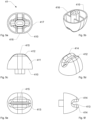
- the Figures 1 to 4 show a scenting device 1 according to the invention for a vehicle with a housing 2 and a fragrance container 3 arranged in the housing 2.
- the fragrance container 3 is replaceable. It can be removed from the housing 2 and a new fragrance container 3 can be inserted into the housing 2.
- the scenting device 1 has holding devices 4 with which the scenting device 1 can be mounted on a ventilation system in the interior of the vehicle.
- the Fig. 1 shows the scenting device 1 viewed from the front.
- Outlet openings 5 are arranged on the front of the scenting device 1.
- the front is therefore also referred to as the outlet side 6.
- outlet openings can also be provided on one or both side walls of the housing 2 and/or on its top and/or on its bottom.
- the Fig. 2 and 3 show the scenting device 1 viewed from the rear.
- Inlet openings 7 are arranged on the rear of the scenting device 1.
- the rear is therefore also referred to as the inlet side 8.
- the inlet side 8 is directed towards the ventilation and the outlet side 6 is directed away from the ventilation.
- the air comes into contact with the fragrance in the fragrance container 3, is enriched with fragrance molecules and leaves the housing 2 of the scenting device 1 through the outlet openings 5.
- the air enters the interior of the vehicle and scents the interior.
- the fragrance container 3, as in Fig. 2 shown, is intended as a replaceable scented stick, wherein the scented stick comprises a composite material of at least one polymer, in particular an elastomer, and the fragrance or consists of such a material.
- the polymer is enriched with the fragrance and acts as its carrier.
- the scented stick preferably has several passage openings 9 through which the air emerging from the ventilation slot can flow. By providing the passage openings 9, the surface area is increased at which the air emerging from the ventilation slot comes into contact with the fragrance, which results in an increased enrichment of the scenting device. 1 with fragrance molecules.
- the passage openings 9 are preferably aligned with the flow direction of the air from the ventilation slot.
- the fragrance can also be provided in the form of granules that are contained in a cage.
- the housing 2 has a housing opening 21 at one of its ends, which can be closed with a housing cover 22.
- the user opens the housing cover 22. This is attached to the housing via a rotating hinge and thus remains connected to the housing 2 even in the open position.
- the housing cover 22 has a curved shape.
- the longer section 221 of the housing cover 22 forms the lateral end of the housing 2.
- the shorter section 222 of the housing cover 22 extends along a section of the long side of the housing 2.
- the curved shape of the housing cover 22 has the advantage that the housing opening 21 is designed to be correspondingly large and the fragrance container 3 can be inserted comfortably.
- the housing 2 and thus also the outlet side 6 have an elongated shape with a long side 61 and a short side 62.
- Several outlet openings 5 are arranged on the outlet side 6. They each have the shape of an elongated slot and are arranged parallel and equidistant from one another.
- the outlet openings 5 are each arranged at an angle to the long side 61 and at an angle to the short side 62. In other words, the outlet openings 5 are neither arranged parallel to the long side 61 nor parallel to the short side 62. In the present embodiment, "at an angle” means that the outlet openings 5 designed as slots are arranged at an angle of 45° to the long side 61 and at an angle of 45° to the short side 62. The outlet openings 5 each extend approximately over the entire length of the short side 62.
- Three coupling devices 10 are arranged on the inlet side 8.
- a holding device 4 can be coupled to each of the three coupling devices 10.
- the three coupling devices 10 are spaced apart from one another and inlet openings 7 are arranged between them.
- FIG. 2 A first variant is shown for mounting the scenting device 1 to the ventilation system of the vehicle.
- a holding device 4 with a rubber cap 41 is coupled to each of the outer coupling devices 10.
- the middle coupling device 10 is left free and is not coupled to any holding device 4.
- the rubber caps 41 are made of an elastic material and are designed in such a way that they can be inserted between two The holding devices 4 with the rubber caps 41 can thus be inserted into a ventilation slot in the vehicle interior.
- This means that the dimensions of the rubber caps 41 are selected depending on the dimensions, in particular the width, of the ventilation slot in such a way that the scenting device 1 can be attached to the ventilation slot by inserting/placing the rubber caps 41 into the ventilation slot and holding them there in a clamped manner.
- the rubber caps 41 can be plugged onto the holding devices 4. This means that the rubber caps 41 can be easily replaced.
- the housing 2 is preferably elongated. If it is mounted on a ventilation slot, it extends along the ventilation slot. Both holding devices 4 are arranged in the same ventilation slot. It is of course also possible to arrange the housing 2 transversely to the ventilation slots, with the holding devices 4 then being inserted into different ventilation slots.
- FIG. 3 A second variant is shown for mounting the scenting device 1 on the vehicle's ventilation system.
- the outer coupling devices 10 are left free and are not coupled to any holding device 4. Only the middle coupling device 10 has a holding device 4 arranged thereon, which has a spreading element 42.
- the spreading element 42 comprises two spreading members 43 and, like the rubber caps 41, can be clamped between two slats of the vehicle's ventilation system.
- the holding device 4 with the rubber cap 41 and the holding device 4 with the spreading element 42 represent different types of holding devices 4, which are designed differently.
- All three coupling devices 10 are designed identically. This means that both the holding devices 4 with the rubber caps 41 as well as the holding device 4 with the spreading element 42 can be coupled with all three coupling devices and thus exchanged with each other. According to the claim, each of the holding devices 4 can thus be coupled with one of the at least one coupling device 10.
- the coupling devices 10 couple to the holding devices 4 in the form of a snap connection.
- the coupling devices 10 have a square frame 101.
- the frame 101 is closed on three sides and has a frame opening 102 on its underside.
- two gaps 103 are arranged on the left and right sides in the frame 101.
- the holding device 4 comprises a flat, square plate 44 to which, depending on the type of holding device 4, either the rubber caps 41 or the expansion element 42 are connected. Elevations 45 are arranged on the plate 44, which, in the snapped-in position, can engage in the gaps 103 of the frame 101 of the coupling device 10.
- a user can couple the holding device 4 to the coupling device 10 by pushing the plate 44 of the holding device 4 from below through the frame opening 102 under the frame 101.
- the frame 101 deforms elastically because the elevations 45 press on the frame 101.
- the user pushes the plate 44 further until the elevations 45 appear in the gaps 103.
- the frame 101 deforms back and the plate 44 is snapped into the frame 101.
- the holding device 4 and the coupling device 10 are coupled to one another.
- a user wants to decouple the holding device 4 from the coupling device 10, he moves the holding device 4 downwards so that the plate 44 is guided out of the frame 101 through the frame opening 102.
- the user must apply a certain force for this movement, ie for removing the snap connection, since the frame 101 is elastically deformed again due to the elevations 45.
- the user has different options available for mounting the scenting device 1 on the ventilation in the vehicle.
- the user can use the holding devices 4 with the rubber caps 41 for mounting, and on the other hand the holding device 4 with the spreading element 42.
- the user thus has a kit which includes the housing 2 with the fragrance container 3 and the different types of holding devices 4.
- the kit can also contain rubber caps 41 of different sizes.
- the user has a total of three options available for mounting the scenting device 1 on the ventilation in the interior of the vehicle. Mounting is carried out using the smaller rubber caps 41, the larger rubber caps 41 or the spreading element 42. The user selects the option from the three options which is best suited to mounting the scenting device 1 depending on the design of the ventilation.
- Fig. 4 shows an exploded view of the individual parts of the scenting device 1.
- the fragrance container 3 is not visible.
- the housing 2 comprises a rear housing cover 23, a front housing frame 24, which frames a front housing cover 25.
- the housing cover 25 comprises the already mentioned outlet openings 5 on the outlet side 6. Also shown is the already mentioned housing cover 22, which can close the housing opening 21.
- a sliding device with a sliding container 11 is arranged within the housing 2.
- the sliding container comprises a base 110, a front wall with inclined outlet openings 111 and a rear wall with vertical inlet openings 112. There is space between the walls of the sliding container 11 so that the fragrance container 3 can be arranged within the sliding container 11.
- the sliding container 11 On the inside of the housing 2 there are webs 26 on which the sliding container 11 rests on the bottom or which it touches with its side walls. This keeps the contact area between the housing 2 and the sliding container 11 as small as possible. The sliding container 11 can be easily moved within the housing 2.
- a plate-shaped handle 113 is arranged on its upper side, which protrudes through the upper side of the housing 2.
- the handle 113 thus protrudes neither through the inlet side 8 nor through the outlet side 6.
- the handle 113 is also in Fig. 1 visible.
- the fragrance container 3 Since the fragrance container 3 is arranged inside the sliding container 11 and does not touch the housing 2, the fragrance container 3 moves in the same way as the sliding container 11 relative to the housing 2. As a result, the fragrance container 3 does not rub against the housing 2 during the movement. Friction only occurs between the sliding container 11 and the webs 26 of the housing 2. The movement is thus controlled, with only slight friction and is independent of whether the fragrance container 3 was cleanly inserted into the sliding container 11 by the user.
- the user By moving the sliding container 11, the user can open and close the inlet openings 7 and the outlet openings 5.
- the struts of the sliding container 11 cover the inlet openings 7 and the outlet openings 5. Air cannot flow through the scenting device 1.
- the outlet openings 111 of the sliding container 11 are congruent with the outlet openings 5 of the housing 2 and the inlet openings 112 of the sliding container 11 are congruent with the inlet openings 7 of the housing 2. Air can flow through the scenting device 1 and be enriched with fragrance molecules from the fragrance container 3.
- Fig. 5a to 5f show the rubber caps 41 arranged on the holding devices 4 in a detailed view and from different perspectives.
- the rubber cap 41 has a base surface 410, a lateral surface 411 and an upper side 412 opposite the base surface 410. Since the rubber cap 41 shown in Fig. 6 has a rounded upper side 412, the upper side 412 forms a component of the lateral surface 411.
- the base surface is the surface of the rubber cap which, when installed, faces the housing of the scenting device.
- the top surface is the surface of the rubber cap which, when installed, faces away from the housing of the scenting device.
- An elongated groove 413 is arranged on the upper side 412 of the rubber cap 41.
- the groove 413 separates the upper side 412 into two parallel upper edges 414. These upper edges 414 each have a straight section 415.
- the base surface 410 of the rubber cap 41 has a circumference or an edge line with two straight sections 416. These two straight sections 416 are connected to each other by two semicircles 417.
- the base area 410 thus resembles an elliptical shape, although it is not an elliptical shape because the edge line has straight sections 416.
Landscapes
- Health & Medical Sciences (AREA)
- Epidemiology (AREA)
- Life Sciences & Earth Sciences (AREA)
- Animal Behavior & Ethology (AREA)
- General Health & Medical Sciences (AREA)
- Public Health (AREA)
- Veterinary Medicine (AREA)
- Engineering & Computer Science (AREA)
- Mechanical Engineering (AREA)
- Disinfection, Sterilisation Or Deodorisation Of Air (AREA)
- Air-Conditioning For Vehicles (AREA)
- Packaging Of Annular Or Rod-Shaped Articles, Wearing Apparel, Cassettes, Or The Like (AREA)
Claims (13)
- Dispositif de parfumage (1) pour un véhicule comprenant- un boîtier (2)- un réservoir de parfum (3) placé dans le boîtier (2),- au moins un dispositif de couplage (10) disposé sur le boîtier (2),- au moins un dispositif de support (4) pour fixer le dispositif de parfumage (1) à un système de ventilation à l'intérieur du véhicule,dans lequel le dispositif de support (4) peut être couplé et découplé du dispositif de couplage (10), caractérisé en ce que le dispositif de parfumage comprend au moins deux dispositifs de support (4) de construction différente, les deux dispositifs de support (4) pouvant être couplés à l'un d'au moins un dispositif de couplage (10).
- Dispositif de parfumage selon la revendication 1, dans lequel au moins trois dispositifs de couplage (10) sont disposés sur le boîtier (2), à chacun desquels l'un des dispositifs de support (4) peut être couplé, en particulier
dans lequel les trois dispositifs de couplage (10) sont espacés les uns des autres, et/ou dans lequel des ouvertures d'entrée (7) sont prévues entre les trois dispositifs de couplage (10), par lesquelles l'air peut s'écouler dans le boîtier (2). - Dispositif de parfumage selon l'une des revendications précédentes, dans lequel le dispositif de couplage (10) et les dispositifs de support (4) sont conçus de manière à se coupler l'un à l'autre sous la forme d'un raccord rapide.
- Dispositif de parfumage selon l'une des revendications précédentes, dans lequel le dispositif de couplage (10) a un cadre (101) et les dispositifs de support (4) ont une plaque plate (44), conçue de manière à ce que la plaque (44) des dispositifs de support (4) puisse être poussée sous le cadre (101) du dispositif de couplage (10) pour le couplage,
en particulier, la plaque (44) comportant au moins une élévation (45) qui s'engage dans les interstices (103) du cadre en position de couplage. - Dispositif de parfumage selon l'une des revendications précédentes, dans lequel au moins un des dispositifs de support (4) comprend un capuchon en caoutchouc (41), en particulier- dans lequel le capuchon en caoutchouc (41) est conçu de manière à pouvoir être serré entre deux grilles d'aération, et/ou- dans lequel le capuchon en caoutchouc (41) peut être retiré du dispositif de support (4).
- Dispositif de parfumage selon la revendication 5, dans lequel le dispositif de parfumage (1) a au moins deux dispositifs de support (4) avec les capuchons en caoutchouc (41), dans lequel les au moins deux dispositifs de support (4) ont des capuchons en caoutchouc (41) de tailles différentes.
- Dispositif de parfumage selon la revendication 5 ou 6, dans lequel le capuchon en caoutchouc (41) a une surface latérale (411), une surface de base (410) et une surface supérieure (412) opposée à la surface de base (410) .
- Dispositif de parfumage selon la revendication 7, dans lequel une rainure (413) est disposée sur la face supérieure (412) du capuchon en caoutchouc (41) et/ou dans lequel deux bords supérieurs parallèles (414) sont disposés sur la face supérieure (412) du capuchon en caoutchouc (41), en particulier dans lequel les deux bords supérieurs (414) ont chacun une section rectiligne (415).
- Dispositif de parfumage selon la revendication 7 ou 8, dans lequel une ligne de bord de la surface de base (410) a au moins une, en particulier deux sections rectilignes (416),
en particulier, dans lequel la ligne de bord comprend deux demi-cercles (417) ou demi ellipses qui relient les deux sections rectilignes (416). - Dispositif de parfumage selon l'une des revendications précédentes, dans lequel au moins un des dispositifs de support (4) comprend un élément d'écartement (42), en particulier- dans lequel l'élément d'écartement (42) est configuré de manière à pouvoir être serré entre deux grilles de ventilation, et/ou- dans lequel l'élément d'écartement (42) comporte au moins deux éléments d'écartement (43).
- Dispositif de parfumage selon l'une des revendications 5 à 9 et selon la revendication 10, dans lequel le dispositif de support (4) peut être couplé au capuchon en caoutchouc (41) et le dispositif de support (4) peut être couplé à l'élément d'écartement (42) sur tous les dispositifs de couplage (4).
- Dispositif de parfumage selon l'une des revendications précédentes, dans lequel exactement trois dispositifs de couplage (10) sont disposés sur le boîtier (2) et l'un des trois dispositifs de couplage (10) est disposé au centre entre les deux autres dispositifs de couplage extérieurs (10),
en particulier, dans lequel- seul le dispositif de couplage (10) disposé au centre est couplé à l'un des dispositifs de support (4), ou- seuls les deux dispositifs de couplage extérieurs (10) sont couplés à l'un des dispositifs de support (4) . - Dispositif de parfumage selon la revendication 11 et 12, dans lequel- le dispositif de couplage (10) disposé au centre est couplé au dispositif de support (4) avec l'élément d'écartement (42), et en particulieraucun dispositif de support (4) n'est couplé aux deux dispositifs de couplage extérieurs (10), oules deux dispositifs de couplage extérieurs (10) sont chacun couplé à un dispositif de support (4) au capuchon en caoutchouc (41), et en particulier aucun dispositif de support (4) n'est couplé au dispositif de couplage disposé au centre (10).
Priority Applications (4)
| Application Number | Priority Date | Filing Date | Title |
|---|---|---|---|
| EP21194251.1A EP4144384B1 (fr) | 2021-09-01 | 2021-09-01 | Dispositif de diffusion de parfum dans un véhicule |
| JP2022135620A JP2023035979A (ja) | 2021-09-01 | 2022-08-29 | 車両のための芳香デバイス |
| CN202211053197.6A CN115721759A (zh) | 2021-09-01 | 2022-08-31 | 用于车辆的气味散发装置 |
| US17/900,268 US20230067503A1 (en) | 2021-09-01 | 2022-08-31 | Scenting device for a vehicle |
Applications Claiming Priority (1)
| Application Number | Priority Date | Filing Date | Title |
|---|---|---|---|
| EP21194251.1A EP4144384B1 (fr) | 2021-09-01 | 2021-09-01 | Dispositif de diffusion de parfum dans un véhicule |
Publications (3)
| Publication Number | Publication Date |
|---|---|
| EP4144384A1 EP4144384A1 (fr) | 2023-03-08 |
| EP4144384C0 EP4144384C0 (fr) | 2024-10-09 |
| EP4144384B1 true EP4144384B1 (fr) | 2024-10-09 |
Family
ID=77595385
Family Applications (1)
| Application Number | Title | Priority Date | Filing Date |
|---|---|---|---|
| EP21194251.1A Active EP4144384B1 (fr) | 2021-09-01 | 2021-09-01 | Dispositif de diffusion de parfum dans un véhicule |
Country Status (4)
| Country | Link |
|---|---|
| US (1) | US20230067503A1 (fr) |
| EP (1) | EP4144384B1 (fr) |
| JP (1) | JP2023035979A (fr) |
| CN (1) | CN115721759A (fr) |
Families Citing this family (2)
| Publication number | Priority date | Publication date | Assignee | Title |
|---|---|---|---|---|
| FR3166073A1 (fr) * | 2024-09-09 | 2026-03-13 | Cpc - Creation Parfum Conseil | Cartouche olfactive pour dispositif de dispense sélective de substances odorantes. |
| US12465152B1 (en) | 2024-11-12 | 2025-11-11 | Travis R. Lewis | Accessories for use with bed sheet retention systems |
Family Cites Families (6)
| Publication number | Priority date | Publication date | Assignee | Title |
|---|---|---|---|---|
| CN201009707Y (zh) * | 2006-03-28 | 2008-01-23 | 汪玉华 | 空气清新盒 |
| DE102011001637B4 (de) * | 2011-03-29 | 2013-06-06 | Supair-Tel Ag | Beduftungsvorrichtung für ein Fahrzeug |
| CH709702A2 (de) * | 2014-05-27 | 2015-11-30 | Supair Tel Ag | Beduftungsvorrichtung zur Anordnung in einem Fahrzeug. |
| US10500299B2 (en) * | 2016-05-11 | 2019-12-10 | Ekaterina Lalo | Encapsulated air freshener for home AC |
| KR20190000337U (ko) * | 2017-07-27 | 2019-02-11 | 주식회사 제이케이윅스 | 방향 기능을 제공하는 차량용 다기능 거치대 |
| US11059353B1 (en) * | 2019-07-23 | 2021-07-13 | Hopkins Manufacturing Corporation | Vehicle air freshener |
-
2021
- 2021-09-01 EP EP21194251.1A patent/EP4144384B1/fr active Active
-
2022
- 2022-08-29 JP JP2022135620A patent/JP2023035979A/ja active Pending
- 2022-08-31 CN CN202211053197.6A patent/CN115721759A/zh active Pending
- 2022-08-31 US US17/900,268 patent/US20230067503A1/en active Pending
Also Published As
| Publication number | Publication date |
|---|---|
| EP4144384A1 (fr) | 2023-03-08 |
| US20230067503A1 (en) | 2023-03-02 |
| JP2023035979A (ja) | 2023-03-13 |
| EP4144384C0 (fr) | 2024-10-09 |
| CN115721759A (zh) | 2023-03-03 |
Similar Documents
| Publication | Publication Date | Title |
|---|---|---|
| DE7016034U (de) | Duese zum absaugen von fluessigkeiten zur verwendung bei einer mit unterdruck arbeitenden reinigungsvorrichtung. | |
| EP2694305B1 (fr) | Diffuseur de parfum pour un véhicule | |
| EP4144384B1 (fr) | Dispositif de diffusion de parfum dans un véhicule | |
| DE4237968C2 (de) | Trennwandelement zur Schubladeneinteilung von Schubladen | |
| DE10123969C1 (de) | Filteranordnung | |
| DE202017103842U1 (de) | Lüftungsgitter mit hohlem Aktuator zum Tragen eines Duftelements | |
| EP3093172A1 (fr) | Systeme d'assemblage d'un echangeur thermique | |
| EP1609643B1 (fr) | Dispositif pour améliorer l'air pour l'utilisation dans des véhicules automobiles et cartouche pour le dispositif d'amélioration d'air | |
| DE3328998C2 (de) | Befestigungsanordnung für ein Wischerblatt und dabei verwendbarer Verriegelungseinsatz | |
| EP3606779B1 (fr) | Élément de guidage d'air comprenant un élément de friction et un diffuseur d'air | |
| EP3000521A1 (fr) | Élement de filtre destine a filtrer un fluide a l'aide d'un materiau de filtre plie | |
| EP4144383B1 (fr) | Dispositif de diffusion de parfum dans un véhicule | |
| DE102011102603B4 (de) | Kennzeichenhalterung für Fahrzeuge | |
| EP4144385B1 (fr) | Dispositif de diffusion de parfum dans un véhicule | |
| DE102008023877B4 (de) | Verfahren zur Herstellung eines Feuchtwerksgehäuses, sowie Feuchtwerksgehäuse eines Sprühfeuchtwerks | |
| DE202005011078U1 (de) | Abdichtelement für eine Filteraufnahme | |
| DE2319871B2 (de) | Scheibenwischer | |
| DE102019123149B4 (de) | Staubfilterbeutel | |
| DE102010046315A1 (de) | Klimaanlage für Kraftfahrzeuge | |
| DE19828233A1 (de) | Wandkonsole | |
| DE19956130C1 (de) | Vorrichtung zum lösbaren Verrasten zweier Bauteile | |
| DE2852079C2 (de) | Vorrichtung zur Beheizung und/oder Belüftung von Fahrerkabinen, Fahrgasträumen od.dgl. in Nutzfahrzeugen | |
| DE10064181C2 (de) | Schieber zum Verschließen einer Befestigungsöffnung in einer Abdeckleiste für einen Dachkanal eines Kraftfahrzeugs | |
| DE102020113515B3 (de) | Behälteraufnahmevorrichtung und Halterung hierzu | |
| DE202005011727U1 (de) | Filterelement |
Legal Events
| Date | Code | Title | Description |
|---|---|---|---|
| PUAI | Public reference made under article 153(3) epc to a published international application that has entered the european phase |
Free format text: ORIGINAL CODE: 0009012 |
|
| STAA | Information on the status of an ep patent application or granted ep patent |
Free format text: STATUS: THE APPLICATION HAS BEEN PUBLISHED |
|
| AK | Designated contracting states |
Kind code of ref document: A1 Designated state(s): AL AT BE BG CH CY CZ DE DK EE ES FI FR GB GR HR HU IE IS IT LI LT LU LV MC MK MT NL NO PL PT RO RS SE SI SK SM TR |
|
| REG | Reference to a national code |
Ref country code: HK Ref legal event code: DE Ref document number: 40086483 Country of ref document: HK |
|
| STAA | Information on the status of an ep patent application or granted ep patent |
Free format text: STATUS: REQUEST FOR EXAMINATION WAS MADE |
|
| 17P | Request for examination filed |
Effective date: 20230830 |
|
| RBV | Designated contracting states (corrected) |
Designated state(s): AL AT BE BG CH CY CZ DE DK EE ES FI FR GB GR HR HU IE IS IT LI LT LU LV MC MK MT NL NO PL PT RO RS SE SI SK SM TR |
|
| GRAP | Despatch of communication of intention to grant a patent |
Free format text: ORIGINAL CODE: EPIDOSNIGR1 |
|
| STAA | Information on the status of an ep patent application or granted ep patent |
Free format text: STATUS: GRANT OF PATENT IS INTENDED |
|
| RIC1 | Information provided on ipc code assigned before grant |
Ipc: A61L 9/04 20060101ALI20240327BHEP Ipc: A61L 9/12 20060101AFI20240327BHEP |
|
| INTG | Intention to grant announced |
Effective date: 20240416 |
|
| GRAS | Grant fee paid |
Free format text: ORIGINAL CODE: EPIDOSNIGR3 |
|
| GRAA | (expected) grant |
Free format text: ORIGINAL CODE: 0009210 |
|
| STAA | Information on the status of an ep patent application or granted ep patent |
Free format text: STATUS: THE PATENT HAS BEEN GRANTED |
|
| AK | Designated contracting states |
Kind code of ref document: B1 Designated state(s): AL AT BE BG CH CY CZ DE DK EE ES FI FR GB GR HR HU IE IS IT LI LT LU LV MC MK MT NL NO PL PT RO RS SE SI SK SM TR |
|
| REG | Reference to a national code |
Ref country code: CH Ref legal event code: EP |
|
| REG | Reference to a national code |
Ref country code: DE Ref legal event code: R096 Ref document number: 502021005409 Country of ref document: DE |
|
| REG | Reference to a national code |
Ref country code: IE Ref legal event code: FG4D Free format text: LANGUAGE OF EP DOCUMENT: GERMAN |
|
| U01 | Request for unitary effect filed |
Effective date: 20241009 |
|
| U07 | Unitary effect registered |
Designated state(s): AT BE BG DE DK EE FI FR IT LT LU LV MT NL PT RO SE SI Effective date: 20241029 |
|
| PG25 | Lapsed in a contracting state [announced via postgrant information from national office to epo] |
Ref country code: HR Free format text: LAPSE BECAUSE OF FAILURE TO SUBMIT A TRANSLATION OF THE DESCRIPTION OR TO PAY THE FEE WITHIN THE PRESCRIBED TIME-LIMIT Effective date: 20241009 Ref country code: IS Free format text: LAPSE BECAUSE OF FAILURE TO SUBMIT A TRANSLATION OF THE DESCRIPTION OR TO PAY THE FEE WITHIN THE PRESCRIBED TIME-LIMIT Effective date: 20250209 |
|
| PG25 | Lapsed in a contracting state [announced via postgrant information from national office to epo] |
Ref country code: ES Free format text: LAPSE BECAUSE OF FAILURE TO SUBMIT A TRANSLATION OF THE DESCRIPTION OR TO PAY THE FEE WITHIN THE PRESCRIBED TIME-LIMIT Effective date: 20241009 |
|
| PG25 | Lapsed in a contracting state [announced via postgrant information from national office to epo] |
Ref country code: NO Free format text: LAPSE BECAUSE OF FAILURE TO SUBMIT A TRANSLATION OF THE DESCRIPTION OR TO PAY THE FEE WITHIN THE PRESCRIBED TIME-LIMIT Effective date: 20250109 |
|
| PG25 | Lapsed in a contracting state [announced via postgrant information from national office to epo] |
Ref country code: GR Free format text: LAPSE BECAUSE OF FAILURE TO SUBMIT A TRANSLATION OF THE DESCRIPTION OR TO PAY THE FEE WITHIN THE PRESCRIBED TIME-LIMIT Effective date: 20250110 |
|
| PG25 | Lapsed in a contracting state [announced via postgrant information from national office to epo] |
Ref country code: PL Free format text: LAPSE BECAUSE OF FAILURE TO SUBMIT A TRANSLATION OF THE DESCRIPTION OR TO PAY THE FEE WITHIN THE PRESCRIBED TIME-LIMIT Effective date: 20241009 |
|
| PG25 | Lapsed in a contracting state [announced via postgrant information from national office to epo] |
Ref country code: RS Free format text: LAPSE BECAUSE OF FAILURE TO SUBMIT A TRANSLATION OF THE DESCRIPTION OR TO PAY THE FEE WITHIN THE PRESCRIBED TIME-LIMIT Effective date: 20250109 |
|
| PG25 | Lapsed in a contracting state [announced via postgrant information from national office to epo] |
Ref country code: SM Free format text: LAPSE BECAUSE OF FAILURE TO SUBMIT A TRANSLATION OF THE DESCRIPTION OR TO PAY THE FEE WITHIN THE PRESCRIBED TIME-LIMIT Effective date: 20241009 |
|
| PG25 | Lapsed in a contracting state [announced via postgrant information from national office to epo] |
Ref country code: SK Free format text: LAPSE BECAUSE OF FAILURE TO SUBMIT A TRANSLATION OF THE DESCRIPTION OR TO PAY THE FEE WITHIN THE PRESCRIBED TIME-LIMIT Effective date: 20241009 |
|
| PG25 | Lapsed in a contracting state [announced via postgrant information from national office to epo] |
Ref country code: CZ Free format text: LAPSE BECAUSE OF FAILURE TO SUBMIT A TRANSLATION OF THE DESCRIPTION OR TO PAY THE FEE WITHIN THE PRESCRIBED TIME-LIMIT Effective date: 20241009 |
|
| U20 | Renewal fee for the european patent with unitary effect paid |
Year of fee payment: 5 Effective date: 20250703 |
|
| PLBE | No opposition filed within time limit |
Free format text: ORIGINAL CODE: 0009261 |
|
| STAA | Information on the status of an ep patent application or granted ep patent |
Free format text: STATUS: NO OPPOSITION FILED WITHIN TIME LIMIT |
|
| 26N | No opposition filed |
Effective date: 20250710 |
|
| REG | Reference to a national code |
Ref country code: CH Ref legal event code: U11 Free format text: ST27 STATUS EVENT CODE: U-0-0-U10-U11 (AS PROVIDED BY THE NATIONAL OFFICE) Effective date: 20251001 |
|
| PGFP | Annual fee paid to national office [announced via postgrant information from national office to epo] |
Ref country code: CH Payment date: 20251001 Year of fee payment: 5 |