EP4144385A1 - Beduftungsvorrichtung für ein fahrzeug - Google Patents
Beduftungsvorrichtung für ein fahrzeug Download PDFInfo
- Publication number
- EP4144385A1 EP4144385A1 EP21194257.8A EP21194257A EP4144385A1 EP 4144385 A1 EP4144385 A1 EP 4144385A1 EP 21194257 A EP21194257 A EP 21194257A EP 4144385 A1 EP4144385 A1 EP 4144385A1
- Authority
- EP
- European Patent Office
- Prior art keywords
- opening
- scenting device
- scenting
- projections
- housing
- Prior art date
- Legal status (The legal status is an assumption and is not a legal conclusion. Google has not performed a legal analysis and makes no representation as to the accuracy of the status listed.)
- Granted
Links
Images
Classifications
-
- B—PERFORMING OPERATIONS; TRANSPORTING
- B60—VEHICLES IN GENERAL
- B60H—ARRANGEMENTS OF HEATING, COOLING, VENTILATING OR OTHER AIR-TREATING DEVICES SPECIALLY ADAPTED FOR PASSENGER OR GOODS SPACES OF VEHICLES
- B60H3/00—Other air-treating devices
- B60H3/0007—Adding substances other than water to the air, e.g. perfume, oxygen
- B60H3/0014—Adding substances other than water to the air, e.g. perfume, oxygen characterised by the location of the substance adding device
-
- A—HUMAN NECESSITIES
- A61—MEDICAL OR VETERINARY SCIENCE; HYGIENE
- A61L—METHODS OR APPARATUS FOR STERILISING MATERIALS OR OBJECTS IN GENERAL; DISINFECTION, STERILISATION OR DEODORISATION OF AIR; CHEMICAL ASPECTS OF BANDAGES, DRESSINGS, ABSORBENT PADS OR SURGICAL ARTICLES; MATERIALS FOR BANDAGES, DRESSINGS, ABSORBENT PADS OR SURGICAL ARTICLES
- A61L9/00—Disinfection, sterilisation or deodorisation of air
- A61L9/01—Deodorant compositions
- A61L9/012—Deodorant compositions characterised by being in a special form, e.g. gels, emulsions
-
- A—HUMAN NECESSITIES
- A61—MEDICAL OR VETERINARY SCIENCE; HYGIENE
- A61L—METHODS OR APPARATUS FOR STERILISING MATERIALS OR OBJECTS IN GENERAL; DISINFECTION, STERILISATION OR DEODORISATION OF AIR; CHEMICAL ASPECTS OF BANDAGES, DRESSINGS, ABSORBENT PADS OR SURGICAL ARTICLES; MATERIALS FOR BANDAGES, DRESSINGS, ABSORBENT PADS OR SURGICAL ARTICLES
- A61L9/00—Disinfection, sterilisation or deodorisation of air
- A61L9/015—Disinfection, sterilisation or deodorisation of air using gaseous or vaporous substances, e.g. ozone
- A61L9/04—Disinfection, sterilisation or deodorisation of air using gaseous or vaporous substances, e.g. ozone using substances evaporated in the air without heating
-
- A—HUMAN NECESSITIES
- A61—MEDICAL OR VETERINARY SCIENCE; HYGIENE
- A61L—METHODS OR APPARATUS FOR STERILISING MATERIALS OR OBJECTS IN GENERAL; DISINFECTION, STERILISATION OR DEODORISATION OF AIR; CHEMICAL ASPECTS OF BANDAGES, DRESSINGS, ABSORBENT PADS OR SURGICAL ARTICLES; MATERIALS FOR BANDAGES, DRESSINGS, ABSORBENT PADS OR SURGICAL ARTICLES
- A61L9/00—Disinfection, sterilisation or deodorisation of air
- A61L9/015—Disinfection, sterilisation or deodorisation of air using gaseous or vaporous substances, e.g. ozone
- A61L9/04—Disinfection, sterilisation or deodorisation of air using gaseous or vaporous substances, e.g. ozone using substances evaporated in the air without heating
- A61L9/12—Apparatus, e.g. holders, therefor
-
- B—PERFORMING OPERATIONS; TRANSPORTING
- B60—VEHICLES IN GENERAL
- B60H—ARRANGEMENTS OF HEATING, COOLING, VENTILATING OR OTHER AIR-TREATING DEVICES SPECIALLY ADAPTED FOR PASSENGER OR GOODS SPACES OF VEHICLES
- B60H1/00—Heating, cooling or ventilating devices
- B60H1/00642—Control systems or circuits; Control members or indication devices for heating, cooling or ventilating devices
- B60H1/0065—Control members, e.g. levers or knobs
-
- A—HUMAN NECESSITIES
- A61—MEDICAL OR VETERINARY SCIENCE; HYGIENE
- A61L—METHODS OR APPARATUS FOR STERILISING MATERIALS OR OBJECTS IN GENERAL; DISINFECTION, STERILISATION OR DEODORISATION OF AIR; CHEMICAL ASPECTS OF BANDAGES, DRESSINGS, ABSORBENT PADS OR SURGICAL ARTICLES; MATERIALS FOR BANDAGES, DRESSINGS, ABSORBENT PADS OR SURGICAL ARTICLES
- A61L2209/00—Aspects relating to disinfection, sterilisation or deodorisation of air
- A61L2209/10—Apparatus features
- A61L2209/15—Supporting means, e.g. stands, hooks, holes for hanging
Definitions
- the invention relates to a scenting device for a vehicle with a housing and a scent container arranged in the housing. Furthermore, the scenting device includes a holding device for attaching the scenting device to a ventilation system in the interior of a vehicle.
- the holding device has a holding element with an opening. The opening has a depth and is designed in the form of an opening or a depression.
- scenting devices which can be hung inside the vehicle and z have a material impregnated with fragrance. Such devices can be produced inexpensively, but their scenting effect can be uneven and the scented body, which is usually hung on the interior rearview mirror, can obstruct the view.
- containers with fragrance are known, which are attached to a ventilation grille in the interior of a vehicle.
- the container for the fragrance has inlet openings, so that air from the ventilation flows into the container, comes into contact with the fragrance and, enriched with fragrance molecules, leaves the container through outlet openings.
- Such containers can be attached to the ventilation grille by means of a clamping part and can also be removed from it again.
- the object is to provide a scenting device that can be reliably mounted on a ventilation system in a vehicle.
- a scenting device for a vehicle having the features of claim 1.
- vehicle includes land vehicles, such as automobiles and trucks, as well as aircraft.
- the scenting device comprises a housing in which a scent container is arranged.
- the scenting device includes a holding device for attaching the scenting device to a ventilation system in the interior of the vehicle.
- the holding device comprises a holding element which has an opening or a hole.
- the opening has a depth and is designed in the form of an opening or a recess.
- the opening is designed in the form of a breakthrough, the opening is continuous through the holding element, ie the depth of the opening corresponds to Thickness of the support element. If the opening is a depression, the opening is not continuous and the opening is only accessible from one side.
- Projections are arranged on the edge or on the walls of the opening. These projections extend from the edge into the interior of the opening. In the depth direction, however, the projections extend to different extents into the interior of the opening; in particular, the projections taper in the depth direction.
- Projections which extend to different depths into the interior of the opening have the advantage that objects of different sizes can be optimally clamped between the projections.
- the scenting device can thus be reliably clamped onto objects of different sizes.
- the holding element can in particular comprise silicone, rubber and/or an elastomer, in particular a thermoplastic elastomer, as material.
- it can comprise a material with a hardness in the range from 30 Shore-A to 90 Shore-A.
- the opening or the depression is designed in the form of a cylinder, in particular in the form of a circular cylinder or in the form of a cylinder with an elliptical base.
- the cylindrical shape includes a lateral surface and a height. The height of the cylindrical shape corresponds to the depth of the opening.
- the projections are arranged on the lateral surface and extend to different extents along the height into the interior of the cylindrical opening.
- Cylindrical shapes with a circle or an ellipse as the base allow round or cylindrical elements, in particular buttons, to be clamped in the holding device.
- the scenting device can thereby be placed on buttons attached to the vent.
- the projections are hollow.
- a hollow interior has higher elasticity lead to protrusions.
- the projections can thus adapt more easily and flexibly to the shape of the elements to be clamped.
- the cavity is designed in the form of a depression and not in the form of an opening.
- the individual projections are advantageously spaced apart from one another, i.e. the individual projections do not touch one another, in particular not at the edge of the opening. In particular, the distance is greater than a third of the width of the projection.
- a space between the projections has the advantage that the projections can also deform elastically in this space. The consequence of this is that the projections can adapt better to the shape of the elements to be clamped and the scenting device remains attached more reliably.
- the opening advantageously has a depth or a height of at least 5 mm, in particular at least 7.5 mm. Such sizes ensure a sufficiently large area within the opening with which the scenting device can adhere to the vent.
- the projections extend along the depth over at least 50%, in particular at least 75%.
- the holding device has a groove which surrounds the opening.
- the groove is circular and is particularly suitable for fastening the holding device to the housing. With the groove provided, the holding device can be clamped onto the housing in a simple manner.
- the scenting device comprises a sliding device with which inlet and/or outlet openings of the housing can be at least partially closed by means of a sliding movement.
- the sliding device has at least two handles, which can be actuated to move the sliding device, in particular wherein operated by pushing the handles into the housing.
- the handles can be designed in such a way that the inlet and/or outlet openings can be opened by actuating one of the at least two handles and the inlet and/or outlet openings can be closed by actuating another of the at least two handles.
- the sliding device has a locking device such that in the locked position the handles cannot be actuated and the sliding movement cannot be carried out. This is intended to prevent unwanted manipulation of the scenting device.
- the fragrance container surrounds the holding element and/or the fragrance container has an opening, in particular a continuous opening, within which the holding element is arranged.
- the scenting device is designed to accommodate precisely one scent container in the housing.
- the scenting device has a non-continuous indentation, which is suitable so that when the scenting device is attached to the vent, a control knob of the vent can engage in the indentation.
- the projections protrude into the depression of the scenting device, so that the control button can be clamped within the depression by means of the projections.
- the scenting device adheres to the control knob and can be flown to by the ventilation.
- the invention also relates to a car that includes a ventilation system with a control button and a scenting device according to the invention.
- the scenting device is arranged on the control button, in particular with the holding element, in particular the projections, clamping the control button.
- the scenting device can be removed from the control knob.
- the arrangement of the scenting device on the control knob has the advantage that it can be mounted directly in front of the ventilation.
- the scenting device is flown against and the air escapes from the scenting device with scent molecules.
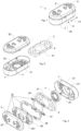
- the Figures 1 to 4 show a scenting device 1 according to the invention for a vehicle with a housing 2 and a scent container 3 arranged in the housing 2.
- the scent container 3 is replaceable. It can be removed from the housing 2 and a new fragrance container 3 can be inserted into the housing 2 .
- the scenting device 1 has a holding device with a holding element 4 . Using the holding device the scenting device 1 can be mounted on a ventilation system in the interior of the vehicle.
- the scenting device 1 comprises outlet openings 5 which are arranged on an outlet side 6 .
- the scenting device 1 includes inlet openings 7 which are arranged on an inlet side 8 .
- the inlet side 8 is arranged opposite the outlet side 6 .
- the inlet side 8 faces the ventilation and the outlet side 6 faces away from the ventilation.
- the air comes into contact with the fragrance in the fragrance container 3, is enriched with fragrance molecules and leaves the housing 2 through the outlet openings 5 Scenting device 1.
- the air enters the interior of the vehicle and scents the interior.
- the fragrance container 3, as in 2 shown is interchangeable, with the fragrance container 3 as a material comprising a composite material made of at least one polymer, in particular an elastomer, and the fragrance or consists of such a material.
- the polymer is enriched with the fragrance and acts as its carrier.
- the scented stick preferably has a plurality of passage openings 9 through which the air emerging from the ventilation slot can flow.
- the provision of the passage openings 9 increases the surface area at which the air exiting the ventilation slit comes into contact with the fragrance, which results in an increased enrichment of the air flowing through the scenting device 1 with fragrance molecules.
- the passage openings 9 are preferably on the Direction of flow of air aligned from the ventilation slot.
- the fragrance can also be provided in the form of granules contained in a cage.
- the housing 2 comprises a housing shell 21 and a housing cover 22.
- the user opens the housing cover 22, replaces the fragrance container 3 and closes the fragrance container 3 in the housing 2 by closing the housing cover 22.
- the 3 1 shows an exploded drawing of the scenting device 1.
- the scenting device 1 comprises a housing cover 21.
- the inlet openings 7 are arranged on the bottom of the housing cover 21.
- the already mentioned holding element 4 can be clamped onto the circular web 24 , the holding element 4 likewise having an opening 41 in the middle.
- the holding element 4 comprises an in 3 invisible bottom groove along its entire circumference. If the holding element 4 is clamped on the circular web 24 of the housing shell 21, the circular web 24 engages in the groove of the holding element 4.
- the fragrance container 3 has a larger circular opening 31 in the middle. If the fragrance container 3 is inserted in the housing 2, the fragrance container 3 surrounds the holding element 4 with its circular opening 31. In other words, the holding element 4 is arranged inside the circular opening 31 of the fragrance container 3.
- the housing cover 22 includes a cover 25, a sliding device 26, a gripping element 27 and a ring 28.
- the cover 25 and the ring 28 are fixedly connected to one another.
- the sliding device 26 and the handle element 27 are also fixedly connected to one another. During a sliding movement, the sliding device 26 and the handle element 27 move relative to the cover 25 and the ring 28.
- the outlet openings 5 are arranged on the cover 25 . These can be opened and closed using the sliding device 26 . To open and close the outlet openings 5 , the user pushes one of the handles 29 arranged on the handle element 27 into the housing cover 22 . The handle element 27, which is permanently connected to the sliding device 26, thereby moves the sliding device 26 relative to the cover 25.
- Arrow 11 points to that handle 29 which the user must press in the direction of arrow 11 in order to open the outlet openings 5 .
- Arrow 12 points to that handle 29 which the user must press in the direction of arrow 12 in order to close the outlet openings 5 .
- the struts of the sliding device 26 cover the outlet openings 5. Air cannot flow through the scenting device 1.
- the outlet openings 5 of the cover 25 are congruent with the passage openings 261 of the sliding device 26. Air can flow through the scenting device 1 and can be enriched with scent molecules from the scent container 3.
- the sliding device 26 is equipped with a locking device. If the sliding device 26 is locked, the outlet openings 5 cannot be closed or opened. The slider 26 is blocked and cannot be moved. It is locked by locking the handle element 27 on Housing 2. By moving one of the handles 29 in the direction of the double arrow 13, the user can lock the sliding device 26 or release the lock.
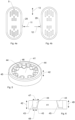
- the Figures 5 and 6 show the holding element 4 in a detailed view.
- the holding element 4 has a circular configuration and includes a centrally arranged opening 41 .
- the thickness of the holding element 4 is referred to as the depth 42 .
- the centrally arranged opening 41 extends over the entire depth 42, is accordingly continuous and is therefore referred to as an opening in the form of a breakthrough.
- the depth 42 is about 8 mm. If the opening 41 were not continuous but closed from one side, it would not be a breakthrough but a depression. Such an embodiment would also be possible.
- a circular cylinder is defined by its base and its lateral surface.
- the base area corresponds to the opening area of the opening 41.
- the lateral area corresponds to the walls 43 of the opening 41.
- the walls 43 surround the opening 41 and correspond to the inner side walls of the holding element 4.
- projections 44 extend into the interior of the opening 41. There are a total of nine projections 44, which are arranged equidistantly from one another along the lateral surface.
- the projections 44 are hollow, with the hollow space 45 not being continuous but being designed in the form of a recess. Because of the cavity 45, the projections can be elastically deformed very well. In 6 the cavity 45 is illustrated by dashed lines.
- adjacent projections 44 there is an intermediate space 46 between adjacent projections 44, ie adjacent projections 44 are spaced apart from one another. Due to the gaps 46, the projections 44 can also be easily deformed elastically.
- FIG. 6 shows a sectional view across the diameter of the holding element 4. For the sake of simplicity, only those two projections 44 that lie in the sectional area are shown. Starting from the edge 43 or from the lateral surface of the holding element 4, the projections 44 protrude into the interior of the opening 41.
- the projections 44 are shaped in such a way that they extend along the depth 42 to different extents into the interior of the opening 41. For example, the in 6 projections 44 shown on their upper sides, starting from the edge 43 over a width 47 into the interior of the opening 41. On their undersides, however, the projections 44 only extend over a width 48. The projections 44 thus extend over different widths along the depth 42 in the interior of opening 41.
- the protrusions 44 are formed so as to continuously extend less far into the inside of the opening 41 from the top to the bottom of the holding member 4 .
- the range of extension is continuously reduced.
- the projections 44 taper along the depth 41.
- the projections 44 extend along the depth 41 over a length 49.
- the length 49 corresponds to approximately 85% of the total depth 41 of the holding element 4.
- the scenting device 1 has a depression which is used to mount the scenting device 1 on a ventilation system in a vehicle.
- this recess consists essentially of the housing opening 23 and the opening 41 of the holding element 4.
- vents have rounded control knobs with which the user can regulate the ventilation strength. If the user wants to mount the scenting device 1 on the ventilation system, he puts the scenting device over such a control button. The control button engages in the recess of the scenting device 1. The scenting device 1 is clamped by means of the projections 44 of the holding element 4 on the control button.
Landscapes
- Health & Medical Sciences (AREA)
- Epidemiology (AREA)
- Life Sciences & Earth Sciences (AREA)
- Animal Behavior & Ethology (AREA)
- General Health & Medical Sciences (AREA)
- Public Health (AREA)
- Veterinary Medicine (AREA)
- Engineering & Computer Science (AREA)
- Mechanical Engineering (AREA)
- Dispersion Chemistry (AREA)
- Chemical & Material Sciences (AREA)
- Thermal Sciences (AREA)
- Physics & Mathematics (AREA)
- Air-Conditioning For Vehicles (AREA)
- Disinfection, Sterilisation Or Deodorisation Of Air (AREA)
- Packaging Of Annular Or Rod-Shaped Articles, Wearing Apparel, Cassettes, Or The Like (AREA)
Abstract
Description
- Die Erfindung betrifft eine Beduftungsvorrichtung für ein Fahrzeug mit einem Gehäuse und einem im Gehäuse angeordneten Duftstoffbehälter. Im Weiteren umfasst die Beduftungsvorrichtung eine Haltevorrichtung zum Anbringen der Beduftungsvorrichtung an einer Lüftung im Innenraum eines Fahrzeuges. Die Haltevorrichtung weist ein Halteelement mit einer Öffnung auf. Die Öffnung weist eine Tiefe auf und ist in Form eines Durchbruchs oder einer Vertiefung ausgestaltet.
- Es sind Beduftungsvorrichtungen bekannt, welche im Fahrzeuginneren aufgehängt werden können und z.B. ein mit Duftstoff getränktes Material aufweisen. Solche Vorrichtungen sind kostengünstig herstellbar, ihre Beduftungswirkung kann aber ungleichmässig sein und der in der Regel am Innenrückspiegel aufgehängte Duftkörper kann sichtbehindernd sein.
- Im Weiteren sind Behälter mit Duftstoff bekannt, welche an einem Lüftungsgitter im Innenraum eines Fahrzeuges befestigt werden. Der Behälter für den Duftstoff weist Einlassöffnungen auf, sodass Luft aus der Lüftung in den Behälter hineinströmt, mit dem Duftstoff in Kontakt gerät und angereichert mit Duftmolekülen den Behälter durch Auslassöffnungen verlässt. Solche Behälter können mittels eines Klemmteils am Lüftungsgitter befestigt und von diesem auch wieder entfernt werden.
- Es stellt sich die Aufgabe, eine Beduftungsvorrichtung bereitzustellen, welche zuverlässig an einer Lüftung eines Fahrzeuges montiert werden kann.
- Diese Aufgabe wird durch eine Beduftungsvorrichtung für ein Fahrzeug mit den Merkmalen des Anspruchs 1 gelöst. Der Begriff "Fahrzeug" umfasst Landfahrzeuge, wie Personenkraftwagen und Lastkraftwagen, und auch Luftfahrzeuge.
- Die erfindungsgemässe Beduftungsvorrichtung umfasst ein Gehäuse, in welchem ein Duftstoffbehälter angeordnet ist. Zudem umfasst die Beduftungsvorrichtung eine Haltevorrichtung zum Anbringen der Beduftungsvorrichtung an einer Lüftung im Innenraum des Fahrzeuges. Die Haltevorrichtung umfasst ein Halteelement, welches eine Öffnung oder ein Loch aufweist. Die Öffnung weist eine Tiefe auf und ist in Form eines Durchbruchs oder einer Vertiefung ausgestaltet.
- Ist die Öffnung in Form eines Durchbruchs ausgestaltet, so ist die Öffnung durch das Halteelement durchgängig, d.h. die Tiefe der Öffnung entspricht der Dicke des Halteelements. Handelt es sich bei der Öffnung um eine Vertiefung, ist die Öffnung nicht durchgängig und die Öffnung ist nur einseitig zugänglich.
- Am Rand bzw. an den Wänden der Öffnung sind Vorsprünge angeordnet. Diese Vorsprünge erstrecken sich vom Rand in das Innere der Öffnung. In Richtung der Tiefe erstrecken sich die Vorsprünge aber unterschiedlich weit in das Innere der Öffnung, insbesondere verjüngen sich die Vorsprünge in Richtung der Tiefe.
- Vorsprünge, welche sich in Richtung der Tiefe unterschiedlich weit in das Innere der Öffnung erstrecken, haben den Vorteil, dass zwischen den Vorsprüngen unterschiedlich grosse Gegenstände optimal eingeklemmt werden können. Die Beduftungsvorrichtung kann somit zuverlässig auf unterschiedlich grosse Gegenstände geklemmt werden.
- Das Halteelement kann insbesondere als Material Silikon, Gummi und/oder ein Elastomer, insbesondere ein thermoplastisches Elastomer, umfassen. Insbesondere kann es ein Material mit einer Härte im Bereich von 30 Shore-A bis 90 Shore-A umfassen.
- Mit Vorteil sind der Durchbruch oder die Vertiefung in Form eines Zylinders ausgestaltet, insbesondere in Form eines Kreiszylinders oder in Form eines Zylinders mit einer elliptischen Grundfläche. Die zylindrische Form umfasst eine Mantelfläche und eine Höhe. Die Höhe der zylindrischen Form entspricht der Tiefe der Öffnung. Die Vorsprünge sind an der Mantelfläche angeordnet und erstrecken sich entlang der Höhe unterschiedlich weit in das Innere der zylindrischen Öffnung.
- Zylindrische Formen mit einem Kreis oder eine Ellipse als Grundfläche erlauben, in der Haltevorrichtung runde oder Zylindrische Elemente, insbesondere Knöpfe, einzuklemmen. Die Beduftungsvorrichtung kann dadurch auf an der Lüftung angebrachte Knöpfe angeordnet werden.
- Insbesondere sind die Vorsprünge hohl ausgebildet. Ein hohles Innere hat eine höhere Elastizität der Vorsprünge zur Folge. Die Vorsprünge können sich somit einfacher und flexibler an die Form einzuklemmender Elemente anpassen. Insbesondere ist der Hohlraum in der Form einer Vertiefung und nicht in der Form eines Durchbruchs ausgestaltet.
- Mit Vorteil sind die einzelnen Vorsprünge voneinander beabstandet, d.h. die einzelnen Vorsprünge berühren sich nicht, insbesondere nicht am Rand der Öffnung. Der Abstand ist insbesondere grösser als ein Drittel der Breite des Vorsprungs. Ein Zwischenraum zwischen den Vorsprüngen hat den Vorteil, dass sich die Vorsprünge auch in diesen Zwischenraum elastisch verformen können. Dies hat zur Folge, dass sich die Vorsprünge besser an die Form einzuklemmender Elemente anpassen können und die Beduftungsvorrichtung zuverlässiger haften bleibt.
- Vorteilhaft weist die Öffnung eine Tiefe bzw. eine Höhe von mindestens 5 mm, insbesondere von mindestens 7.5 mm auf. Solche Grössen gewährleisten eine genügend grosse Fläche innerhalb der Öffnung, mit welcher die Beduftungsvorrichtung an der Lüftung haften kann.
- Insbesondere erstrecken sich die Vorsprünge entlang der Tiefe über mindestens 50%, insbesondere mindestens 75%.
- In einer besonderen Ausführungsform weist die Haltevorrichtung eine Nut auf, welche die Öffnung umgibt. Insbesondere ist die Nut kreisförmig und insbesondere geeignet, die Haltevorrichtung am Gehäuse zu befestigen. Mit der vorgesehenen Nut kann die Haltevorrichtung in einfacher Weise auf das Gehäuse aufgespannt werden.
- Insbesondere umfasst die Beduftungsvorrichtung eine Schiebevorrichtung mit welcher Einlass- und/oder Auslassöffnungen des Gehäuses mittels einer Schiebebewegung zumindest teilweise verschlossen werden können.
- Mit Vorteil weist die Schiebevorrichtung mindestens zwei Griffe aufweist, durch dessen Betätigung die Schiebbevorrichtung verschiebbar ist, insbesondere wobei die Betätigung durch Hineindrücken der Griffe in das Gehäuse erfolgt. Die Griffe können derart ausgestaltet sein, dass durch Betätigung des einen der mindestens zwei Griffe die Einlass- und/oder Auslassöffnungen geöffnet und durch Betätigung eines anderen der mindestens zwei Griffe die Einlass- und/oder Auslassöffnungen verschlossen werden können.
- Insbesondere weist die Schiebevorrichtung eine Arretiervorrichtung auf, derart dass in arretierter Stellung die Griffe nicht betätigbar und die Schiebebewegung nicht durchführbar sind. Dadurch sollen ungewollte Manipulationen an der Beduftungsvorrichtung verhindert werden.
- In einer besonderen Ausführungsform umgibt der Duftstoffbehälter das Halteelement und/oder der Duftstoffbehälter weist eine Öffnung, insbesondere eine durchgängige Öffnung, auf, innerhalb welcher das Halteelement angeordnet ist. Insbesondere ist die Beduftungsvorrichtung ausgestaltet, genau einen Duftstoffbehälter im Gehäuse aufzunehmen.
- Vorteilhaft weist die Beduftungsvorrichtung eine nicht durchgängige Vertiefung auf, welche geeignet ist, dass bei Anbringung der Beduftungsvorrichtung an der Lüftung ein Regelknopf der Lüftung in die Vertiefung greifen kann. Insbesondere ragen die Vorsprünge in die Vertiefung der Beduftungsvorrichtung hinein, sodass mittels den Vorsprüngen der Regelknopf innerhalb der Vertiefung eingeklemmt werden kann. Die Beduftungsvorrichtung haftet dadurch am Regelknopf und kann von der Lüftung angeströmt werden.
- Die Erfindung betrifft auch ein Auto, welches eine Lüftung mit einem Regelknopf und eine erfindungsgemässe Beduftungsvorrichtung umfasst. Die Beduftungsvorrichtung ist auf dem Regelknopf angeordnet, insbesondere wobei das Halteelement, insbesondere die Vorsprünge, den Regelknopf einklemmt. Insbesondere kann die Beduftungsvorrichtung vom Regelknopf entfernt werden.
- Die Anordnung der Beduftungsvorrichtung auf dem Regelknopf hat den Vorteil, dass diese stabil direkt vor der Lüftung montiert werden kann. Die Beduftungsvorrichtung wird angeströmt und die Luft entweicht mit Duftmolekülen aus der Beduftungsvorrichtung.
- Weitere Ausgestaltungen, Vorteile und Anwendungen der Erfindung ergeben sich aus den abhängigen Ansprüchen und aus der nun folgenden Beschreibung anhand der Figuren. Dabei zeigen:
-
Fig. 1 eine erfindungsgemässe Beduftungsvorrichtung; -
Fig. 2 die Beduftungsvorrichtung beim Austausch des Duftstoffbehälters; -
Fig. 3 eine Explosionszeichnung der Beduftungsvorrichtung; -
Fig. 4a die Beduftungsvorrichtung mit Sicht von oben und geschlossenen Auslassöffnungen; -
Fig. 4b die Beduftungsvorrichtung mit Sicht von oben und geöffneten Auslassöffnungen; -
Fig. 5 das Halteelement der Beduftungsvorrichtung; und -
Fig. 6 eine stark vereinfachte Schnittansicht durch das Halteelement derFig. 5 . - Die
Figuren 1 bis 4 zeigen eine erfindungsgemässe Beduftungsvorrichtung 1 für ein Fahrzeug mit einem Gehäuse 2 und einem im Gehäuse 2 angeordneten Duftstoffbehälter 3. Der Duftstoffbehälter 3 ist auswechselbar. Er kann dem Gehäuse 2 entnommen und ein neuer Duftstoffbehälter 3 kann in das Gehäuse 2 eingesetzt werden. Die Beduftungsvorrichtung 1 weist eine Haltevorrichtung mit einem Halteelement 4 auf. Mittels der Haltevorrichtung kann die Beduftungsvorrichtung 1 an einer Lüftung im Innenraum des Fahrzeuges montiert werden. - Die Beduftungsvorrichtung 1 umfasst Auslassöffnungen 5, welche auf einer Auslassseite 6 angeordnet sind. Zudem umfasst die Beduftungsvorrichtung 1 Einlassöffnungen 7, welche auf einer Einlassseite 8 angeordnet sind. Die Einlassseite 8 ist der Auslassseite 6 gegenüberliegend angeordnet.
- Ist die Beduftungsvorrichtung 1 an der Lüftung im Innenraum des Fahrzeuges montiert, ist die Einlassseite 8 zur Lüftung gerichtet und die Auslassseite 6 ist von der Lüftung weggerichtet. Luft strömt aus der Lüftung durch die Einlassöffnungen 7, in das Gehäuse 2 und in den im Gehäuse 2 angeordneten Duftstoffbehälter 3. Die Luft kommt mit dem Duftstoff im Duftstoffbehälter 3 in Kontakt, wird mit Duftmolekülen angereichert und verlässt durch die Auslassöffnungen 5 das Gehäuse 2 der Beduftungsvorrichtung 1. Die Luft gelangt in den Innenraum des Fahrzeuges und beduftet den Innenraum.
- Der Duftstoffbehälter 3, wie in
Fig. 2 dargestellt, ist auswechselbar, wobei der Duftstoffbehälter 3 als Material einen Kompositwerkstoff aus zumindest einem Polymer, insbesondere einem Elastomer, und dem Duftstoff umfasst bzw. aus einem solchen Material besteht. Dabei ist das Polymer mit dem Duftstoff angereichert und fungiert als dessen Träger. Der Duftstift weist bevorzugt mehrere Durchlassöffnungen 9 auf, durch welche die aus dem Lüftungsschlitz austretende Luft strömen kann. Durch das Vorsehen der Durchlassöffnungen 9 wird die Oberfläche vergrössert, an welcher die aus dem Lüftungsschlitz austretende Luft mit dem Duftstoff in Kontakt gerät, was eine erhöhte Anreicherung der die Beduftungsvorrichtung 1 durchströmenden Luft mit Duftstoffmolekülen zur Folge hat. Die Durchlassöffnungen 9 sind vorzugsweise auf die Strömungsrichtung der Luft aus dem Lüftungsschlitz ausgerichtet. Alternativ kann der Duftstoff auch in Form eines Granulats vorgesehen sein, das in einem Käfig enthalten ist. - Wie in
Fig. 2 gezeigt, umfasst das Gehäuse 2 eine Gehäusehülle 21 und einen Gehäusedeckel 22. Für den Austausch des Duftstoffbehälters 3 öffnet der Benutzer den Gehäusedeckel 22, tauscht den Duftstoffbehälter 3 aus und schliesst den Duftstoffbehälter 3 durch Schliessen des Gehäusedeckels 22 in das Gehäuse 2 ein. - Die
Fig. 3 zeigte eine Explosionszeichnung der Beduftungsvorrichtung 1. Wie erwähnt umfasst die Beduftungsvorrichtung 1 eine Gehäusehülle 21. Am Boden der Gehäusehülle 21 sind die Einlassöffnungen 7 angeordnet. Mittig ist eine grössere Gehäuseöffnung 23 vorhanden, welche von einem kreisförmigen Steg 24 umgeben ist. Auf den kreisförmigen Steg 24 ist das bereits erwähnte Halteelement 4 aufspannbar, wobei das Halteelement 4 mittig ebenfalls eine Öffnung 41 aufweist. Das Halteelement 4 umfasst eine inFig. 3 nicht sichtbare, bodenseitige Nut entlang seines gesamten Umfangs. Ist das Halteelement 4 auf dem kreisförmigen Steg 24 der Gehäusehülle 21 aufgespannt, greift der kreisförmige Steg 24 in die Nut des Halteelements 4. - Zwischen dem Halteelement 4 und den Seitenwänden der Gehäusehülle 21 ist Raum vorhanden, in welchen der Duftstoffbehälter 3 einsetzbar ist. Mittig weist der Duftstoffbehälter 3 eine grössere kreisförmige Öffnung 31 auf. Ist der Duftstoffbehälter 3 im Gehäuse 2 eingesetzt, umgibt der Duftstoffbehälters 3 mit seiner kreisförmigen Öffnung 31 das Halteelement 4. Mit anderen Worten ist das Halteelement 4 innerhalb der kreisförmigen Öffnung 31 des Duftstoffbehälters 3 angeordnet.
- Die übrigen in
Fig. 3 gezeigten Einzelteile sind Bestandteil des Gehäusedeckels 22. Der Gehäusedeckel 22 umfasst eine Abdeckung 25, eine Schiebevorrichtung 26, ein Griffelement 27 und einen Ring 28. Die Abdeckung 25 und der Ring 28 sind fix miteinander verbunden. Die Schiebevorrichtung 26 und das Griffelement 27 sind ebenfalls fix miteinander verbunden. Bei einer Schiebebewegung bewegen sich die Schiebevorrichtung 26 und das Griffelement 27 relativ zur Abdeckung 25 und zum Ring 28. - An der Abdeckung 25 sind die Auslassöffnungen 5 angeordnet. Diese können mittels der Schiebevorrichtung 26 geöffnet und geschlossen werden. Zum Öffnen und Schliessen der Auslassöffnungen 5 stösst der Benutzer jeweils einen der am Griffelement 27 angeordneten Griffe 29 in den Gehäusedeckel 22 hinein. Das mit der Schiebevorrichtung 26 fix verbundene Griffelement 27 bewegt dadurch die Schiebevorrichtung 26 relativ zur Abdeckung 25.
- In
Fig. 4 sind die möglichen Schiebebewegungen illustriert. Pfeil 11 zeigt auf denjenigen Griff 29, welchen der Benutzer in Pfeilrichtung 11 drücken muss, um die Auslassöffnungen 5 zu öffnen. Pfeil 12 zeigt auf denjenigen Griff 29, welchen der Benutzer in Pfeilrichtung 12 drücken muss, um die Auslassöffnungen 5 zu schliessen. - Im geschlossenen Zustand verdecken die Streben der Schiebevorrichtung 26 die Auslassöffnungen 5. Luft kann die Beduftungsvorrichtung 1 nicht durchströmen. Im offenen Zustand sind die Auslassöffnungen 5 der Abdeckung 25 deckungsgleich mit den Durchlassöffnungen 261 der Schiebevorrichtung 26. Luft kann durch die Beduftungsvorrichtung 1 strömen und mit Duftstoffmolekülen des Duftstoffbehälters 3 angereichert werden.
- Die Schiebevorrichtung 26 ist mit einer Arretiervorrichtung ausgestattet. Ist die Schiebevorrichtung 26 arretiert, können die Auslassöffnungen 5 nicht verschlossen oder geöffnet werden. Die Schiebevorrichtung 26 ist blockiert und kann nicht bewegt werden. Die Arretierung erfolgt durch ein Verrasten des Griffelementes 27 am Gehäuse 2. Durch Bewegung eines der Griffe 29 in Richtung des Doppelpfeils 13 kann der Benutzer die Schiebevorrichtung 26 arretieren bzw. die Arretierung lösen.
- Die
Fig. 5 und 6 zeigen das Halteelement 4 in detaillierter Ansicht. Das Halteelement 4 ist kreisförmig ausgestaltet und umfasst eine zentral angeordnete Öffnung 41. Die Dicke des Halteelements 4 wird als Tiefe 42 bezeichnet. - Die zentral angeordnete Öffnung 41 erstreckt sich über die gesamte Tiefe 42, ist entsprechend durchgehend und wird deshalb als eine Öffnung in Form eines Durchbruchs bezeichnet. Die Tiefe 42 beträgt ca. 8 mm. Wäre die Öffnung 41 nicht durchgehend, sondern von einer Seite verschlossen, wäre sie nicht als Durchbruch, sondern als eine Vertiefung zu bezeichnen. Auch eine solche Ausführung wäre möglich.
- Aufgrund der kreisförmigen Öffnung 41 weist der Durchbruch die Form eines Kreiszylinders auf. Ein Kreiszylinder wird durch seine Grundfläche und seine Mantelfläche definiert. Die Grundfläche entspricht der Öffnungsfläche der Öffnung 41. Die Mantelfläche entspricht den Wänden 43 der Öffnung 41. Die Wände 43 umgeben die Öffnung 41 und entsprechen den inneren Seitenwänden des Halteelements 4.
- Ausgehend von den Wänden 43 bzw. der Mantelfläche erstrecken sich Vorsprünge 44 in das Innere der Öffnung 41. Insgesamt sind es neun Vorsprünge 44, welche entlang der Mantelfläche äquidistant zueinander angeordnet sind. Die Vorsprünge 44 sind hohl ausgestaltet, wobei der Hohlraum 45 nicht durchgängig, sondern in Form einer Vertiefung ausgestaltet ist. Aufgrund des Hohlraums 45 lassen sich die Vorsprünge sehr gut elastisch deformieren. In
Fig. 6 wird der Hohlraum 45 durch gestrichelte Linien illustriert. - Im Weiteren ist zwischen benachbarten Vorsprüngen 44 jeweils ein Zwischenraum 46 vorhanden, d.h. benachbarte Vorsprünge 44 sind voneinander beabstandet. Aufgrund der Zwischenräume 46 können sich die Vorsprünge 44 ebenfalls elastisch gut deformieren.
-
Fig. 6 zeigt eine Schnittansicht über den Durchmesser des Halteelements 4. Zur Vereinfachung sind lediglich diejenigen zwei Vorsprünge 44 eingezeichnet, welche in der Schnittfläche liegen. Ausgehend vom Rand 43 bzw. von der Mantelfläche des Halteelements 4 ragen die Vorsprünge 44 in das Innere der Öffnung 41. Die Vorsprünge 44 sind dabei derart geformt, dass sie sich entlang der Tiefe 42 unterschiedlich weit in das Innere der Öffnung 41 erstrecken. Beispielsweise erstrecken sich die inFig. 6 gezeigten Vorsprünge 44 an ihren Oberseiten ausgehend vom Rand 43 über eine Weite 47 in das Innere der Öffnung 41. An ihren Unterseiten erstrecken sich die Vorsprünge 44 allerdings lediglich über eine Weite 48. Somit erstrecken sich die Vorsprünge 44 über unterschiedlich Weiten entlang der Tiefe 42 in das Innere der Öffnung 41. - In der vorliegenden Ausführungsform sind die Vorsprünge 44 derart geformt, dass sie sich ausgehend von der Oberseite zur Unterseite des Halteelements 4 kontinuierlich weniger weit in das Innere der Öffnung 41 erstrecken. Die Erstreckungsweite reduziert sich kontinuierlich. Mit anderen Worten verjüngen sich die Vorsprünge 44 entlang der Tiefe 41.
- Entlang der Tiefe 41 erstrecken sich die Vorsprünge 44 über eine Länge 49. Die Länge 49 entspricht dabei etwa 85% der gesamten Tiefe 41 des Halteelements 4.
- Gesamthaft betrachtet weist die Beduftungsvorrichtung 1 eine Vertiefung auf, welche der Montage der Beduftungsvorrichtung 1 an einer Lüftung in einem Fahrzeug dient. Diese Vertiefung besteht in der vorliegenden Ausführungsform im Wesentlichen aus der Gehäuseöffnung 23 und der Öffnung 41 des Halteelements 4.
- Gewisse Lüftungen weisen rundlich geformte Regelknöpfe auf, mit welchen der Benutzer die Lüftungsstärke regulieren kann. Möchte der Benutzer die Beduftungsvorrichtung 1 an die Lüftung montieren, so stülpt er die Beduftungsvorrichtung über einen solchen Regelknopf. Der Regelknopf greift dabei in die Vertiefung der Beduftungsvorrichtung 1. Die Beduftungsvorrichtung 1 klemmt sich mittels den Vorsprüngen 44 des Halteelements 4 am Regelknopf fest.
- Während in der vorliegenden Anmeldung bevorzugte Ausführungen der Erfindung beschrieben sind, ist klar darauf hinzuweisen, dass die Erfindung nicht auf diese beschränkt ist und in auch anderer Weise innerhalb des Umfangs der folgenden Ansprüche ausgeführt werden kann.
Claims (15)
- Beduftungsvorrichtung (1) für ein Fahrzeug umfassend- ein Gehäuse (2),- einen im Gehäuse (2) angeordneten Duftstoffbehälter (3),- eine Haltevorrichtung zum Anbringen der Beduftungsvorrichtung (1) an einer Lüftung im Innenraum des Fahrzeuges,wobei die Haltevorrichtung ein Halteelement (4) mit einer Öffnung (41) aufweist und die Öffnung (41) in Form eines Durchbruchs oder einer Vertiefung ausgestaltet ist und eine Tiefe (42) aufweist,dadurch gekennzeichnet, dass am Rand (43) bzw. an den Wänden der Öffnung (41) Vorsprünge (44) angeordnet sind, wobei sich die Vorsprünge (44) entlang der Tiefe (42) unterschiedlich weit in das Innere der Öffnung (41) erstrecken, insbesondere entlang der Tiefe (42) verjüngen.
- Beduftungsvorrichtung nach Anspruch 1, wobei der Durchbruch oder die Vertiefung die Form eines Zylinders, insbesondere eines Kreiszylinders oder eines Zylinders mit einer elliptischen Grundfläche, mit einer Mantelfläche und einer Höhe aufweist, wobei die Vorsprünge (44) an der Mantelfläche angeordnet sind und sich entlang der Höhe unterschiedlich weit in das Innere des Zylinders erstrecken.
- Beduftungsvorrichtung nach einem der vorangehenden Ansprüche, wobei die Vorsprünge (44) hohl sind,
insbesondere mit einem Hohlraum (45), welcher in Form einer Vertiefung und nicht in Form eines Durchbruchs ausgestaltet ist. - Beduftungsvorrichtung nach einem der vorangehenden Ansprüche, wobei die einzelnen Vorsprünge (44) voneinander beabstandet sind, insbesondere mittels eines Abstands beabstandet, wobei der Abstand grösser als ein Drittel der Breite des Vorsprungs (44) ist.
- Beduftungsvorrichtung nach einem der vorangehenden Ansprüche, wobei die Öffnung (41) eine Tiefe (42) von mindestens 5 mm, insbesondere mindestens 7.5 mm aufweist.
- Beduftungsvorrichtung nach einem der vorangehenden Ansprüche, wobei sich die Vorsprünge (44) entlang der Tiefe (42) über mindestens 50%, insbesondere mindestens 75%, der Tiefe erstrecken.
- Beduftungsvorrichtung nach einem der vorangehenden Ansprüche, wobei die Haltevorrichtung eine die Öffnung (41) umgebende Nut, insbesondere eine kreisförmige Nut, aufweist, insbesondere geeignet, um die Haltevorrichtung am Gehäuse (2) zu befestigen.
- Beduftungsvorrichtung nach einem der vorangehenden Ansprüche, aufweisend eine Schiebevorrichtung (26) mit welcher Einlassöffnungen (7) und/oder Auslassöffnungen (5) des Gehäuses (2) mittels einer Schiebebewegung zumindest teilweise verschliessbar sind.
- Beduftungsvorrichtung nach Anspruch 8, wobei die Schiebevorrichtung (26) mindestens zwei Griffe (29) aufweist, durch dessen Betätigung die Schiebbevorrichtung (26) verschiebbar ist,
insbesondere wobei die Betätigung durch Hineindrücken der Griffe (29) in das Gehäuse (2) erfolgt. - Beduftungsvorrichtung nach einem der Ansprüche 8 oder 9, wobei die Schiebevorrichtung (26) eine Arretiervorrichtung aufweist, derart dass in arretierter Stellung die Griffe (29) nicht betätigbar und die Schiebebewegung nicht durchführbar sind.
- Beduftungsvorrichtung nach einem der vorangehenden Ansprüche, wobei der Duftstoffbehälter (3),- das Halteelement (4) umgibt, und/oder- eine Öffnung (31) aufweist, innerhalb welcher das Halteelement (4) angeordnet ist,
insbesondere wobei die Beduftungsvorrichtung (1) ausgestaltet ist, genau einen Duftstoffbehälter (3) im Gehäuse (2) aufzunehmen. - Beduftungsvorrichtung nach einem der vorangehenden Ansprüche, aufweisend eine Vertiefung (23, 41), geeignet, dass bei Anbringung der Beduftungsvorrichtung (1) an der Lüftung ein Regelknopf der Lüftung in die Vertiefung (23, 41) greifen kann.
- Beduftungsvorrichtung nach Anspruch 11, wobei die Vorsprünge (44) in die Vertiefung (23, 41) der Beduftungsvorrichtung (1) hineinragen, geeignet, um den Regelknopf einzuklemmen.
- Auto, aufweisend eine Lüftung mit einem Regelknopf und einer Beduftungsvorrichtung (1) nach einem der vorangehenden Ansprüche, wobei die Beduftungsvorrichtung (1) auf dem Regelknopf angeordnet ist, insbesondere wobei das Halteelement (4), insbesondere die Vorsprünge (44), den Regelknopf einklemmt.
- Auto nach Anspruch 14, wobei die Beduftungsvorrichtung (1) vom Regelknopf entfernbar ist.
Priority Applications (4)
| Application Number | Priority Date | Filing Date | Title |
|---|---|---|---|
| EP21194257.8A EP4144385B1 (de) | 2021-09-01 | 2021-09-01 | Beduftungsvorrichtung für ein fahrzeug |
| JP2022135623A JP2023035980A (ja) | 2021-09-01 | 2022-08-29 | 車両のための芳香デバイス |
| US17/900,401 US12514947B2 (en) | 2021-09-01 | 2022-08-31 | Scenting device for a vehicle |
| CN202211053180.0A CN115721758A (zh) | 2021-09-01 | 2022-08-31 | 用于车辆的气味散发装置 |
Applications Claiming Priority (1)
| Application Number | Priority Date | Filing Date | Title |
|---|---|---|---|
| EP21194257.8A EP4144385B1 (de) | 2021-09-01 | 2021-09-01 | Beduftungsvorrichtung für ein fahrzeug |
Publications (3)
| Publication Number | Publication Date |
|---|---|
| EP4144385A1 true EP4144385A1 (de) | 2023-03-08 |
| EP4144385C0 EP4144385C0 (de) | 2024-07-17 |
| EP4144385B1 EP4144385B1 (de) | 2024-07-17 |
Family
ID=77595388
Family Applications (1)
| Application Number | Title | Priority Date | Filing Date |
|---|---|---|---|
| EP21194257.8A Active EP4144385B1 (de) | 2021-09-01 | 2021-09-01 | Beduftungsvorrichtung für ein fahrzeug |
Country Status (4)
| Country | Link |
|---|---|
| US (1) | US12514947B2 (de) |
| EP (1) | EP4144385B1 (de) |
| JP (1) | JP2023035980A (de) |
| CN (1) | CN115721758A (de) |
Cited By (1)
| Publication number | Priority date | Publication date | Assignee | Title |
|---|---|---|---|---|
| US12465152B1 (en) | 2024-11-12 | 2025-11-11 | Travis R. Lewis | Accessories for use with bed sheet retention systems |
Citations (2)
| Publication number | Priority date | Publication date | Assignee | Title |
|---|---|---|---|---|
| US20200331326A1 (en) * | 2019-04-18 | 2020-10-22 | Energizer Brands II, LLC | Hollow volatile substance diffuser |
| US11059353B1 (en) * | 2019-07-23 | 2021-07-13 | Hopkins Manufacturing Corporation | Vehicle air freshener |
Family Cites Families (2)
| Publication number | Priority date | Publication date | Assignee | Title |
|---|---|---|---|---|
| US8485454B1 (en) * | 2009-12-30 | 2013-07-16 | American Covers, Inc. | Rotatable and adjustable air freshener |
| US9743737B1 (en) * | 2015-07-20 | 2017-08-29 | La Sonya D. Malbrough | Universal hair scent diffuser |
-
2021
- 2021-09-01 EP EP21194257.8A patent/EP4144385B1/de active Active
-
2022
- 2022-08-29 JP JP2022135623A patent/JP2023035980A/ja active Pending
- 2022-08-31 CN CN202211053180.0A patent/CN115721758A/zh active Pending
- 2022-08-31 US US17/900,401 patent/US12514947B2/en active Active
Patent Citations (2)
| Publication number | Priority date | Publication date | Assignee | Title |
|---|---|---|---|---|
| US20200331326A1 (en) * | 2019-04-18 | 2020-10-22 | Energizer Brands II, LLC | Hollow volatile substance diffuser |
| US11059353B1 (en) * | 2019-07-23 | 2021-07-13 | Hopkins Manufacturing Corporation | Vehicle air freshener |
Cited By (1)
| Publication number | Priority date | Publication date | Assignee | Title |
|---|---|---|---|---|
| US12465152B1 (en) | 2024-11-12 | 2025-11-11 | Travis R. Lewis | Accessories for use with bed sheet retention systems |
Also Published As
| Publication number | Publication date |
|---|---|
| EP4144385C0 (de) | 2024-07-17 |
| EP4144385B1 (de) | 2024-07-17 |
| US20230073998A1 (en) | 2023-03-09 |
| US12514947B2 (en) | 2026-01-06 |
| CN115721758A (zh) | 2023-03-03 |
| JP2023035980A (ja) | 2023-03-13 |
Similar Documents
| Publication | Publication Date | Title |
|---|---|---|
| DE102011001637B4 (de) | Beduftungsvorrichtung für ein Fahrzeug | |
| EP2501357B1 (de) | Vorrichtung zum zuführen oder entnehmen einer flüssigkeit in ein oder aus einem behältnis | |
| EP2164531B1 (de) | Beduftungsvorrichtung, insbesondere für ein kraftfahrzeug | |
| EP1878484A1 (de) | Luftdurchtrittsvorrichtung | |
| EP1207969A1 (de) | Entlüftungsvorrichtung bei einem kolben für eine kartusche | |
| DE2160561B2 (de) | ||
| DE2945600A1 (de) | Aerosol-spruehkopf fuer mehrere spruehmuster | |
| WO2012104351A1 (de) | Funktionskopf für einen duftstoffbehälter | |
| EP4144385B1 (de) | Beduftungsvorrichtung für ein fahrzeug | |
| EP1609643B1 (de) | Luftverbesserungsvorrichtung zur Verwendung in Kraftfahrzeugen und Kartusche für die Luftverbesserungsvorrichtung | |
| DE102006022661A1 (de) | Beduftungssystem, insbesondere für ein Kraftfahrzeug | |
| DE69510391T2 (de) | Entlüfter für Klimaregelung in Kraftfahrzeugen mit individuellem auswählbarem Verteiler und Strömungskonzentriervorrichtung | |
| DE4218684A1 (de) | Tragbares und fixierbares mini-safe | |
| DE102009044280A1 (de) | Produktspender | |
| EP4144384B1 (de) | Beduftungsvorrichtung für ein fahrzeug | |
| DE20207512U1 (de) | Duftspender | |
| DE1475178A1 (de) | Einstueckiger,aus Kunststoff gegossener Betaetigungsknopf fuer eine Verteilvorrichtung | |
| DE1289074B (de) | Ventil zum Fuellen des Tanks von mit Fluessiggas betreibbaren Geraeten | |
| DE1181873B (de) | Vorrichtung zur Abgabe von fluessigen Medien, insbesondere Schuhpflegemittel | |
| EP0431497A2 (de) | Handbetätigbare, doppelt wirkende Dosier- und/oder Zerstäuberpumpe | |
| CH453240A (de) | Auf eine Sprühdose aufsteckbare Betätigungsvorrichtung | |
| DE102008005834A1 (de) | Ventileinrichtung mit Handhilfsbetätigungseinrichtung | |
| DE102005025409A1 (de) | Luftverbesserungsvorrichtung zur Verwendung in Kraftfahrzeugen und Kartusche für die Luftverbesserungsvorrichtung | |
| EP2345544B1 (de) | Ventilmarker mit Durchgangskanal im Kugelsitz | |
| DE102016012899A1 (de) | Patrizenteil eines Druckknopfs und Druckknopf mit einem solchen Patrizenteil |
Legal Events
| Date | Code | Title | Description |
|---|---|---|---|
| PUAI | Public reference made under article 153(3) epc to a published international application that has entered the european phase |
Free format text: ORIGINAL CODE: 0009012 |
|
| STAA | Information on the status of an ep patent application or granted ep patent |
Free format text: STATUS: THE APPLICATION HAS BEEN PUBLISHED |
|
| AK | Designated contracting states |
Kind code of ref document: A1 Designated state(s): AL AT BE BG CH CY CZ DE DK EE ES FI FR GB GR HR HU IE IS IT LI LT LU LV MC MK MT NL NO PL PT RO RS SE SI SK SM TR |
|
| REG | Reference to a national code |
Ref country code: HK Ref legal event code: DE Ref document number: 40086484 Country of ref document: HK |
|
| STAA | Information on the status of an ep patent application or granted ep patent |
Free format text: STATUS: REQUEST FOR EXAMINATION WAS MADE |
|
| 17P | Request for examination filed |
Effective date: 20230830 |
|
| RBV | Designated contracting states (corrected) |
Designated state(s): AL AT BE BG CH CY CZ DE DK EE ES FI FR GB GR HR HU IE IS IT LI LT LU LV MC MK MT NL NO PL PT RO RS SE SI SK SM TR |
|
| RIC1 | Information provided on ipc code assigned before grant |
Ipc: B60H 1/00 20060101ALI20240102BHEP Ipc: A61L 9/04 20060101ALI20240102BHEP Ipc: B60H 3/00 20060101ALI20240102BHEP Ipc: A61L 9/12 20060101AFI20240102BHEP |
|
| GRAP | Despatch of communication of intention to grant a patent |
Free format text: ORIGINAL CODE: EPIDOSNIGR1 |
|
| STAA | Information on the status of an ep patent application or granted ep patent |
Free format text: STATUS: GRANT OF PATENT IS INTENDED |
|
| INTG | Intention to grant announced |
Effective date: 20240226 |
|
| GRAS | Grant fee paid |
Free format text: ORIGINAL CODE: EPIDOSNIGR3 |
|
| GRAA | (expected) grant |
Free format text: ORIGINAL CODE: 0009210 |
|
| STAA | Information on the status of an ep patent application or granted ep patent |
Free format text: STATUS: THE PATENT HAS BEEN GRANTED |
|
| AK | Designated contracting states |
Kind code of ref document: B1 Designated state(s): AL AT BE BG CH CY CZ DE DK EE ES FI FR GB GR HR HU IE IS IT LI LT LU LV MC MK MT NL NO PL PT RO RS SE SI SK SM TR |
|
| REG | Reference to a national code |
Ref country code: CH Ref legal event code: EP |
|
| REG | Reference to a national code |
Ref country code: DE Ref legal event code: R096 Ref document number: 502021004376 Country of ref document: DE |
|
| REG | Reference to a national code |
Ref country code: IE Ref legal event code: FG4D Free format text: LANGUAGE OF EP DOCUMENT: GERMAN |
|
| U01 | Request for unitary effect filed |
Effective date: 20240718 |
|
| U07 | Unitary effect registered |
Designated state(s): AT BE BG DE DK EE FI FR IT LT LU LV MT NL PT SE SI Effective date: 20240801 |
|
| U20 | Renewal fee for the european patent with unitary effect paid |
Year of fee payment: 4 Effective date: 20240822 |
|
| PG25 | Lapsed in a contracting state [announced via postgrant information from national office to epo] |
Ref country code: NO Free format text: LAPSE BECAUSE OF FAILURE TO SUBMIT A TRANSLATION OF THE DESCRIPTION OR TO PAY THE FEE WITHIN THE PRESCRIBED TIME-LIMIT Effective date: 20241017 |
|
| PG25 | Lapsed in a contracting state [announced via postgrant information from national office to epo] |
Ref country code: GR Free format text: LAPSE BECAUSE OF FAILURE TO SUBMIT A TRANSLATION OF THE DESCRIPTION OR TO PAY THE FEE WITHIN THE PRESCRIBED TIME-LIMIT Effective date: 20241018 Ref country code: PL Free format text: LAPSE BECAUSE OF FAILURE TO SUBMIT A TRANSLATION OF THE DESCRIPTION OR TO PAY THE FEE WITHIN THE PRESCRIBED TIME-LIMIT Effective date: 20240717 |
|
| PG25 | Lapsed in a contracting state [announced via postgrant information from national office to epo] |
Ref country code: IS Free format text: LAPSE BECAUSE OF FAILURE TO SUBMIT A TRANSLATION OF THE DESCRIPTION OR TO PAY THE FEE WITHIN THE PRESCRIBED TIME-LIMIT Effective date: 20241117 |
|
| PG25 | Lapsed in a contracting state [announced via postgrant information from national office to epo] |
Ref country code: HR Free format text: LAPSE BECAUSE OF FAILURE TO SUBMIT A TRANSLATION OF THE DESCRIPTION OR TO PAY THE FEE WITHIN THE PRESCRIBED TIME-LIMIT Effective date: 20240717 |
|
| PG25 | Lapsed in a contracting state [announced via postgrant information from national office to epo] |
Ref country code: RS Free format text: LAPSE BECAUSE OF FAILURE TO SUBMIT A TRANSLATION OF THE DESCRIPTION OR TO PAY THE FEE WITHIN THE PRESCRIBED TIME-LIMIT Effective date: 20241017 Ref country code: ES Free format text: LAPSE BECAUSE OF FAILURE TO SUBMIT A TRANSLATION OF THE DESCRIPTION OR TO PAY THE FEE WITHIN THE PRESCRIBED TIME-LIMIT Effective date: 20240717 |
|
| PG25 | Lapsed in a contracting state [announced via postgrant information from national office to epo] |
Ref country code: RS Free format text: LAPSE BECAUSE OF FAILURE TO SUBMIT A TRANSLATION OF THE DESCRIPTION OR TO PAY THE FEE WITHIN THE PRESCRIBED TIME-LIMIT Effective date: 20241017 Ref country code: PL Free format text: LAPSE BECAUSE OF FAILURE TO SUBMIT A TRANSLATION OF THE DESCRIPTION OR TO PAY THE FEE WITHIN THE PRESCRIBED TIME-LIMIT Effective date: 20240717 Ref country code: NO Free format text: LAPSE BECAUSE OF FAILURE TO SUBMIT A TRANSLATION OF THE DESCRIPTION OR TO PAY THE FEE WITHIN THE PRESCRIBED TIME-LIMIT Effective date: 20241017 Ref country code: IS Free format text: LAPSE BECAUSE OF FAILURE TO SUBMIT A TRANSLATION OF THE DESCRIPTION OR TO PAY THE FEE WITHIN THE PRESCRIBED TIME-LIMIT Effective date: 20241117 Ref country code: HR Free format text: LAPSE BECAUSE OF FAILURE TO SUBMIT A TRANSLATION OF THE DESCRIPTION OR TO PAY THE FEE WITHIN THE PRESCRIBED TIME-LIMIT Effective date: 20240717 Ref country code: GR Free format text: LAPSE BECAUSE OF FAILURE TO SUBMIT A TRANSLATION OF THE DESCRIPTION OR TO PAY THE FEE WITHIN THE PRESCRIBED TIME-LIMIT Effective date: 20241018 Ref country code: ES Free format text: LAPSE BECAUSE OF FAILURE TO SUBMIT A TRANSLATION OF THE DESCRIPTION OR TO PAY THE FEE WITHIN THE PRESCRIBED TIME-LIMIT Effective date: 20240717 |
|
| PG25 | Lapsed in a contracting state [announced via postgrant information from national office to epo] |
Ref country code: SM Free format text: LAPSE BECAUSE OF FAILURE TO SUBMIT A TRANSLATION OF THE DESCRIPTION OR TO PAY THE FEE WITHIN THE PRESCRIBED TIME-LIMIT Effective date: 20240717 |
|
| PG25 | Lapsed in a contracting state [announced via postgrant information from national office to epo] |
Ref country code: MC Free format text: LAPSE BECAUSE OF FAILURE TO SUBMIT A TRANSLATION OF THE DESCRIPTION OR TO PAY THE FEE WITHIN THE PRESCRIBED TIME-LIMIT Effective date: 20240717 |
|
| PG25 | Lapsed in a contracting state [announced via postgrant information from national office to epo] |
Ref country code: CZ Free format text: LAPSE BECAUSE OF FAILURE TO SUBMIT A TRANSLATION OF THE DESCRIPTION OR TO PAY THE FEE WITHIN THE PRESCRIBED TIME-LIMIT Effective date: 20240717 |
|
| PG25 | Lapsed in a contracting state [announced via postgrant information from national office to epo] |
Ref country code: SK Free format text: LAPSE BECAUSE OF FAILURE TO SUBMIT A TRANSLATION OF THE DESCRIPTION OR TO PAY THE FEE WITHIN THE PRESCRIBED TIME-LIMIT Effective date: 20240717 |
|
| PLBE | No opposition filed within time limit |
Free format text: ORIGINAL CODE: 0009261 |
|
| STAA | Information on the status of an ep patent application or granted ep patent |
Free format text: STATUS: NO OPPOSITION FILED WITHIN TIME LIMIT |
|
| 26N | No opposition filed |
Effective date: 20250422 |
|
| PG25 | Lapsed in a contracting state [announced via postgrant information from national office to epo] |
Ref country code: IE Free format text: LAPSE BECAUSE OF NON-PAYMENT OF DUE FEES Effective date: 20240901 |
|
| U20 | Renewal fee for the european patent with unitary effect paid |
Year of fee payment: 5 Effective date: 20250703 |
|
| REG | Reference to a national code |
Ref country code: CH Ref legal event code: U11 Free format text: ST27 STATUS EVENT CODE: U-0-0-U10-U11 (AS PROVIDED BY THE NATIONAL OFFICE) Effective date: 20251001 |
|
| PG25 | Lapsed in a contracting state [announced via postgrant information from national office to epo] |
Ref country code: RO Free format text: LAPSE BECAUSE OF FAILURE TO SUBMIT A TRANSLATION OF THE DESCRIPTION OR TO PAY THE FEE WITHIN THE PRESCRIBED TIME-LIMIT Effective date: 20240717 |
|
| PGFP | Annual fee paid to national office [announced via postgrant information from national office to epo] |
Ref country code: CH Payment date: 20251001 Year of fee payment: 5 |
|
| PG25 | Lapsed in a contracting state [announced via postgrant information from national office to epo] |
Ref country code: CY Free format text: LAPSE BECAUSE OF FAILURE TO SUBMIT A TRANSLATION OF THE DESCRIPTION OR TO PAY THE FEE WITHIN THE PRESCRIBED TIME-LIMIT; INVALID AB INITIO Effective date: 20210901 |
|
| PG25 | Lapsed in a contracting state [announced via postgrant information from national office to epo] |
Ref country code: HU Free format text: LAPSE BECAUSE OF FAILURE TO SUBMIT A TRANSLATION OF THE DESCRIPTION OR TO PAY THE FEE WITHIN THE PRESCRIBED TIME-LIMIT; INVALID AB INITIO Effective date: 20210901 |