EP4144492B1 - Dispositif d'articulation pour robot - Google Patents
Dispositif d'articulation pour robot Download PDFInfo
- Publication number
- EP4144492B1 EP4144492B1 EP21850583.2A EP21850583A EP4144492B1 EP 4144492 B1 EP4144492 B1 EP 4144492B1 EP 21850583 A EP21850583 A EP 21850583A EP 4144492 B1 EP4144492 B1 EP 4144492B1
- Authority
- EP
- European Patent Office
- Prior art keywords
- friction wheel
- shaft
- joint device
- friction
- rotate
- Prior art date
- Legal status (The legal status is an assumption and is not a legal conclusion. Google has not performed a legal analysis and makes no representation as to the accuracy of the status listed.)
- Active
Links
Images



Classifications
-
- B—PERFORMING OPERATIONS; TRANSPORTING
- B25—HAND TOOLS; PORTABLE POWER-DRIVEN TOOLS; MANIPULATORS
- B25J—MANIPULATORS; CHAMBERS PROVIDED WITH MANIPULATION DEVICES
- B25J17/00—Joints
- B25J17/02—Wrist joints
- B25J17/0258—Two-dimensional joints
- B25J17/0275—Universal joints, e.g. Hooke, Cardan, ball joints
-
- B—PERFORMING OPERATIONS; TRANSPORTING
- B25—HAND TOOLS; PORTABLE POWER-DRIVEN TOOLS; MANIPULATORS
- B25J—MANIPULATORS; CHAMBERS PROVIDED WITH MANIPULATION DEVICES
- B25J17/00—Joints
-
- B—PERFORMING OPERATIONS; TRANSPORTING
- B25—HAND TOOLS; PORTABLE POWER-DRIVEN TOOLS; MANIPULATORS
- B25J—MANIPULATORS; CHAMBERS PROVIDED WITH MANIPULATION DEVICES
- B25J9/00—Program-controlled manipulators
- B25J9/10—Program-controlled manipulators characterised by positioning means for manipulator elements
- B25J9/104—Program-controlled manipulators characterised by positioning means for manipulator elements with cables, chains or ribbons
Definitions
- the disclosure relates to a joint device for a robot, and more particularly, to a joint device for a robot having two-directional degrees of freedom of rotation using friction wheels.
- a joint structure used in a robot may be manufactured in such a manner that a plurality of rotation shafts are sequentially combined.
- a joint for a robot has a series structure in which a motor is directly connected to each rotation shaft, a link structure in which a heavy motor is concentrated to a lower end of a mechanism using a wire or a link, or an interference drive structure in which a plurality of degrees of freedom are connected in parallel.
- the interference drive structure is widely used as a joint structure for a robot because a weight can be efficiently distributed by disposing a drive source near an upper shaft, a structure is simple, and modularization can be made in units of shafts.
- interference drive structures mainly use bevel gears or wires.
- a bevel gear In a case where a bevel gear is used, there are problems in that the gear needs to be machined with high precision, the production cost is very high, and it is difficult to support a load in an axial direction.
- a degree of difficulty is high in terms of assembly and maintenance, and the volume of the entire structure increases because the wire needs to have a radius of curvature having a specific value or more.
- US20110296944A1 proposes a robotic joint configured as a 3-axis joint.
- the joint includes an input roll assembly and a pitch-output roll assembly.
- the pitch-output roll assembly includes: a housing; a differential mechanism including left and right input gears, an output gear, a cross element interconnecting the gears, and a clevis supporting the gears and the cross element; a left four-bar linkage coupled to the left input gear; a right four-bar linkage coupled to the right input gear; and first and second linear actuators connected to the left and right four-bar linkages.
- the first and second linear actuators selectively drive the left and right input gears to rotate the output gear about an output roll axis and to rotate the cross element about a pitch axis passing through the cross element and input gears.
- a linear actuator in the input roll assembly rotates the pitch-output roll housing about an input roll axis.
- US20180055584A1 relates to various robotic and/or in vivo medical devices having compact joint configurations and at least three degrees of freedom.
- Other embodiments relate to various medical device components, including forearms having grasper or cautery end effectors, that can be incorporated into certain robotic and/or in vivo medical devices.
- the robot wrist structure comprises a shell, a first motor, a second motor, a first transmission mechanism, a second transmission mechanism, a first driving conical gear, a second driving conical gear, a driven conical gear, a holder, and an output connecting part; the first motor and the second motor are arranged on the shell, the first driving conical gear, the second driving conical gear, and the driven conical gear are rotatably mounted on the holder, the axis of the first driving conical gear is colinear with the axis of the second driving conical gear and is perpendicularly crossed with the driven conical gear, the first driving conical gear, and the second driving conical gear are engaged with the driven conical gear, the first motor is connected with the first driving conical gear through the first transmission mechanism, the second motor is connected with the second driving conical gear through the second transmission mechanism, and the output connecting part is fixedly connected with the driven conical gear.
- the robot wrist structure is diverse in motion mode
- the disclosure provides a joint device for a robot having two-directional degrees of freedom of rotation using friction wheels.
- components required for describing each embodiment of the disclosure are described, and the components are not necessarily limited thereto. Therefore, some components may be changed or omitted and other components may be added. In addition, components may be arranged in different independent devices in a distributed manner.
- FIG. 1 is a perspective view of a joint device for a robot according to an embodiment of the disclosure.
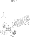
- FIG. 2 is an exploded perspective view of the joint device for the robot of FIG. 1 .
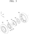
- FIG. 3 is an exploded perspective view of components fitted on a first shaft.
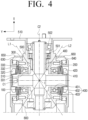
- FIG. 4 is a cross-sectional view taken along line A-A of the joint device for the robot of FIG. 1 .
- a joint device 1 for a robot may include a first shaft 100, a second shaft 200, a first friction wheel 300, a second friction wheel 400, a third friction wheel 500, and a driving device 600.
- the first shaft 100 may rotatably support the first friction wheel 300 and the second friction wheel 400 at opposite ends of the first shaft 100, respectively. Accordingly, the first and second friction wheels 300 and 400 may rotate around the first shaft 100 with the same rotation axis.
- the first shaft 100 may be disposed parallel to a Y axis. That is, the rotation axis of the first and second friction wheels 300 and 400 may be parallel to the Y axis.
- the first shaft 100 may have a cylindrical shape.
- the second shaft 200 may rotatably support the third friction wheel 500 at one end of the second shaft 200. Accordingly, the third friction wheel 500 may rotate around the second shaft 200.
- the second shaft 200 may be disposed perpendicular to the first shaft 100.
- the second shaft 200 may be disposed parallel to an X axis. That is, a rotation axis of the third friction wheel 500 may be parallel to the X axis.
- the second shaft 200 may have a cylindrical shape.
- the second shaft 200 may be integrally formed with the first shaft 100.
- the first and second shafts 100 and 200 may together form an integral shaft having a "T" or "X" shape to rotatably support the first, second, and third friction wheels 300, 400, and 500.
- the first and second shafts 100 and 200 may be formed separately, rather than integrally formed.
- the first friction wheel 300 and the second friction wheel 400 may rotate in a state where they are fitted on the first shaft 100.
- the first and second friction wheels 300 and 400 may have a truncated cone shape.
- the first and second friction wheels 300 and 400 may be arranged to be symmetric with respect to the second shaft 200. Specifically, the first and second friction wheels 300 and 400 may be disposed to have a cross section that becomes smaller as being closer to the second shaft 200.
- the third friction wheel 500 may rotate in a state where they are fitted on the second shaft 200.
- the third friction wheel 500 may have a truncated cone shape.
- the third friction wheel 500 may be disposed to have a cross section that becomes smaller as being closer to the first shaft 100.
- the third friction wheel 500 may contact the first and second friction wheels 300 and 400 simultaneously at different positions. Accordingly, the third friction wheel 500 may be passively rotated by a rotational force transferred from the first and second friction wheels 300 and 400 due to a frictional force generated in portions contacting the first and second friction wheels 300 and 400.
- the first, second, and third friction wheels 300, 400, and 500 may be formed of aluminum, but their material is not limited thereto. Accordingly, it is possible to reduce the weight of the joint device 1 for the robot and lower the overall specifications of the joint device 1 for the robot.
- first, second, and third friction wheels 300, 400, and 500 may smoothly rotate without noise because they continuously contact each other without teeth formed on their surfaces, which does not cause backlash.
- first, second, and third friction wheels 300, 400, and 500 may be produced at a lower cost than gears, and may require fewer parts than wires, thereby reducing maintenance costs.
- a side surface of the third friction wheel 500 may simultaneously contact respective side surfaces of the first and second friction wheels 300 and 400.
- the third friction wheel 500 may contact the first friction wheel 300 along a first line L1, and contact the second friction wheel 400 along a second line L2.
- the first and second lines L1 and L2 may intersect at an intersection between central axes C1 and C2 of the first and second shafts 100 and 200.
- the third friction wheel 500 may rotate in a pitch direction because the third friction wheel 500 receives a frictional force from the first and second friction wheels 300 and 400 in the same direction.
- the pitch direction may be a direction of rotation with respect to a rotation axis parallel to the Y axis.
- the third friction wheel 500 may rotate in a roll direction because the third friction wheel 500 receives a frictional force from the first and second friction wheels 300 and 400 in different directions.
- the roll direction may be a direction of rotation with respect to a rotation axis parallel to the X axis.
- the third friction wheel 500 may be passively rotated by a rotational force transferred from the first and second friction wheels 300 and 400, and may have two degrees of freedom of rotation depending on the rotation directions of the first and second friction wheels 300 and 400. A process in which the third friction wheel 500 rotates based on the two degrees of freedom of rotation will be described in detail with reference to FIGS. 5 and 6 .
- connection plate 510 may be disposed on a front surface of the third friction wheel 500.
- the connection plate 510 may have a disk shape and may be coupled to the third friction wheel 500 to rotate integrally with the third friction wheel 500.
- connection plate 510 Any one of various robot structures may be coupled to the connection plate 510.
- any one of various parts of the robot such as an arm, a hand, a foot, a leg, and a head, may be coupled to the connection plate 510 to rotate together with the third friction wheel 500.
- Bearings 501 and 502 may be disposed between the third friction wheel 500 and the second shaft 200. Although the two bearings 501 and 502 are illustrated, the number of bearings is not limited thereto.
- the bearings 501 and 502 may be angular ball bearings, but the bearing type is not limited thereto.
- the bearings 501 and 502 enables the third friction wheel 500 to easily rotate relative to the second shaft 200, which is stationary.
- the driving device 600 may rotate each of the first and second friction wheels 300 and 400.
- the driving device 600 may include a first motor 610 and a second motor 620.
- the first motor 610 may rotate the first friction wheel 300
- the second motor 620 may rotate the second friction wheel 400.
- the first and second motors 610 and 620 may be supported by a frame 700, and may be positioned behind the first, second, and third friction wheels 300, 400, and 500.
- the driving device 600 may further include a first pulley 630, a second pulley 640, a first timing belt 650, and a second timing belt 660.
- the first and second pulleys 630 and 640 may be fitted on the first shaft 100 to rotate around the first shaft 100.
- the first pulley 630 may be disposed on a rear surface of the first friction wheel 300
- the second pulley 640 may be disposed at a rear surface of the second friction wheel 400.
- the first timing belt 650 may partially surround a circumference of the first pulley 630 to provide a driving force of the first motor 610 to the first pulley 630.
- the first pulley 630 may be coupled to the first friction wheel 300 to rotate integrally with the first friction wheel 300.
- the second timing belt 660 may partially surround a circumference of the second pulley 640 to provide a driving force of the second motor 620 to the second pulley 640, and the second pulley 640 may be coupled to the second friction wheel 400 to rotate integrally with the second friction wheel 400.
- the above-described structure of the driving device 600 is an example, and the structure of the driving device 600 is not limited thereto.
- the driving device 600 may be implemented in any structure as long as it is capable of rotating the first and second friction wheels 300 and 400.
- the joint device 1 for the robot may further include a first pressing member 310 and a second pressing member 410.
- the first pressing member 310 may press the first friction wheel 300 toward the third friction wheel 500.
- the second pressing member 410 may press the second friction wheel 400 toward the third friction wheel 500.
- the first and second pressing members 310 and 410 provide a pre-load to the first and second friction wheels 300 and 400, thereby providing a sufficient frictional force to the third friction wheel 500. Accordingly, a rotational force of the first and second friction wheels 300 and 400 may be easily transferred to the third friction wheel 500.
- the first and second pressing members 310 and 410 may be disk springs fitted on the first shaft 100.
- the disc springs are capable of pressurize the first and second friction wheels 300 and 400, respectively, with a large elastic force even with a small displacement. Accordingly, the rotational force of the first and second friction wheels 300 and 400 can be more effectively transferred to the third friction wheel 500, so that the joint device 1 for the robot can be manufactured in a small size.
- the joint device 1 for the robot may further include a first nut 320 and a second nut 420.
- the first nut 320 may be fitted at one end of the first shaft 100 to support one end of the first pressing member 310.
- the second nut 420 may be fitted at the other end of the first shaft 100 to support one end of the second pressing member 410.
- first and second nuts 320 and 420 may be fixed by screw threads formed on side surfaces of the first shaft 100.
- the pre-load of the first and second pressing members 310 and 410 may be adjusted depending on how much the first and second nuts 320 and 420 are tightened on the first shaft 100.
- the joint device 1 for the robot may further include a first bearing 330 and a second bearing 430.
- the first bearing 330 may be disposed between the first shaft 100 and the first friction wheel 300.
- the second bearing 430 may be disposed between the first shaft 100 and the second friction wheel 400.
- the first and second bearings 330 and 430 enable the first and second friction wheels 300 and 400 to easily rotate relative to the first shaft 100, which is stationary.
- the first and second bearings 330 and 430 may be angular ball bearings, each being capable of transferring an axial-directional load in an easier way.
- the angular ball bearing is capable of transferring a load in an axial direction as well as in a radial direction in an easy way because a straight line connecting contact points between a ball and inner and outer rings forms a predetermined angle with respect to the radial direction.
- the first bearing 330 makes it possible to more easily transfer an elastic force transferred from the first pressing member 310 to the first friction wheel 300.
- the second bearing 430 makes it possible to more easily transfer an elastic force from the second pressing member 410 to the second friction wheel 400.
- the inner ring 331 and the outer ring 333 of the first bearing 330 may contact the first pressing member 310 and the first friction wheel 300, respectively. Accordingly, an elastic force of the first pressing member 310 may be transferred sequentially through the inner ring 331, the ball 332, and the outer ring 333 of the first bearing 330, and finally transferred to the first friction wheel 300.
- the inner ring 431 and the outer ring 433 of the second bearing 430 may contact the second pressing member 410 and the second friction wheel 400, respectively. Accordingly, an elastic force of the second pressing member 410 may be transferred sequentially through the inner ring 431, the ball 432, and the outer ring 433 of the second bearing 430, and finally transferred to the second friction wheel 400.
- the first and second pressing members 310 and 410 may press the inner rings 331 and 431 of the first and second bearings 330 and 430, which are stationary together with the first shaft 100. Accordingly, since the objects pressed by the first and second pressing members 310 and 410 are stationary, it is possible to minimize wear resulting from friction.
- first and second pressing members 310 and 410 may have a convex shape toward the inner rings 331 and 431 of the first and second bearings 330 and 430.
- first and second pressing members 310 and 410 may be cone-shaped disk springs each having an opening in a central portion.
- the above-described shape of the first and second pressing members 310 and 410 makes it possible to press only the inner rings 331 and 431, which are stationary, not the outer rings 333 and 433, which are rotating, respectively.
- the frame 700 may be disposed on a rear side of the joint device 1 for the robot to support the first shaft 100 and the driving device 600.
- this is an example, and the shape and the arrangement of the frame 700 are not limited thereto.
- the joint device 1 for the robot may further include a fourth friction wheel 800.
- the fourth friction wheel 800 may be rotatably supported at the other end of the second shaft 200 intersecting the first shaft 100.
- the fourth friction wheel 800 may contact each of the first and second friction wheels 300 and 400.
- the fourth friction wheel 800 may have a truncated cone shape, and a side surface of the fourth friction wheel 800 may contact the side surfaces of the first and second friction wheels 300 and 400 simultaneously at different positions.
- the fourth friction wheel 800 may have a shape to be symmetric to the third friction wheel 500 with respect to the first shaft 100. Specifically, the fourth friction wheel 800 may have a truncated cone shape with a cross section gradually decreasing toward the first shaft 100.
- the fourth friction wheel 800 may face the third friction wheel 500, and may rotate in the opposite direction to the third friction wheel 500.
- the fourth friction wheel 800 may support an area of each of the first and second pressing members 310 and 410 on the rear side thereof. Accordingly, the fourth friction wheel 800 may prevent the first and second friction wheels 300 and 400 from being deformed or the rotational axis of the first and second friction wheels 300 and 400 from being misaligned due to the elastic force of the first and second pressing members 310 and 410.
- FIG. 5 is a view illustrating a state in which the third friction wheel rotates in the roll direction.
- the first and second friction wheels 300 and 400 may rotate in different directions.
- the third friction wheel 500 rotates around the second shaft 200 in an R4 direction.
- the fourth friction wheel 800 may rotate around the second shaft 200 in an R3 direction as opposed to the third friction wheel 500.
- the third friction wheel 500 may rotate around the second shaft 200 in the R3 direction.
- the fourth friction wheel 800 may rotate around the second shaft 200 in the R4 direction as opposed to the third friction wheel 500.
- the third friction wheel 500 may rotate around the second shaft 200 in the roll direction.
- FIG. 6 is a view illustrating a state in which the third friction wheel rotates in a pitch direction.
- the first and second friction wheels 300 and 400 may rotate in the same direction.
- the third friction wheel 500 may rotate around the first shaft 100 in the R1 direction.
- the fourth friction wheel 800 may rotate around the first shaft 100 in the R2 direction as opposed to the third friction wheel 500.
- the third friction wheel 500 may also rotate around the first shaft 100 in the R2 direction.
- the fourth friction wheel 800 may rotate around the first shaft 100 in the R1 direction as opposed to the third friction wheel 500.
- the frame 700 may rotatably support both ends of the first shaft 100, and the first and second shafts 100 and 200 may be integrally formed.
- the first and second friction wheels 300 and 400 rotate in the same direction
- the first shaft 100, the second shaft 200, and the third friction wheel 500 may rotate around the first shaft 100 in the R1 or R2 direction.
- the third friction wheel 500 may rotate around the first shaft 100 in the pitch direction.
- the third friction wheel 500 may be passively rotated with two degrees of freedom of rotation depending on the rotation directions of the first and second friction wheels 300 and 400.
Landscapes
- Engineering & Computer Science (AREA)
- Robotics (AREA)
- Mechanical Engineering (AREA)
- Friction Gearing (AREA)
- Manipulator (AREA)
Claims (11)
- Dispositif d'articulation (1) pour un robot, le dispositif d'articulation (1) comprenant :un premier arbre (100) ;un second arbre (200) disposé perpendiculairement au premier arbre (100) ;une première roue de friction (300) supportée de manière rotative par une première extrémité du premier arbre (100) ;une deuxième roue de friction (400) supportée de manière rotative par une seconde extrémité du premier arbre (100) ;un dispositif d'entraînement (600) configuré pour faire tourner chacune de la première roue de friction (300) et de la deuxième roue de friction (400) ;une troisième roue de friction (500) supportée de manière rotative par une première extrémité du second arbre (200), et en contact avec la première roue de friction (300) et les deuxièmes roues de friction (400),dans lequel lorsque la première roue de friction (300) et la deuxième roue de friction (400) tournent dans la même direction, la troisième roue de friction tourne dans une direction de pas, etdans lequel lorsque la première roue de friction (300) et la deuxième roue de friction (400) tournent dans des directions différentes, la troisième roue de friction (500) tourne dans une direction de roulis,caractérisé en ce que :
le dispositif d'articulation (1) comprend :un premier élément de pression (310) configuré pour presser la première roue de friction (300) vers la troisième roue de friction (500) ;un second élément de pression (410) configuré pour presser la deuxième roue de friction (400) vers la troisième roue de friction (500) ;un premier roulement à billes angulaire (330) interposé entre le premier arbre (100) et la première roue de friction (300) ; etun second roulement à billes angulaire (430) interposé entre le premier arbre (100) et la deuxième roue de friction (400),dans lequel :le premier roulement à billes angulaire (330) comprend une bague intérieure (331) qui entre en contact avec le premier élément de pression (310), et une bague extérieure (333) qui entre en contact avec la première roue de friction (300), etle second roulement à billes angulaire (430) comprend une bague intérieure (431) qui entre en contact avec le second élément de pression (410), et une bague extérieure (433) qui entre en contact avec la deuxième roue de friction (400). - Dispositif d'articulation (1) selon la revendication 1, dans lequel chacune des première (300) roues de friction, deuxième roues de friction (400) et troisième roues de friction (500) a une forme de cône tronqué, et
dans lequel une surface latérale de la troisième roue de friction (500) entre en contact avec une surface latérale de chacune des première (300) et deuxième roues de friction (400). - Dispositif d'articulation (1) selon la revendication 2, dans lequel la troisième roue de friction (500) entre en contact avec la première roue de friction (300) le long d'une première ligne (L1),dans lequel la troisième roue de friction (500) entre en contact avec la deuxième roue de friction (400) le long d'une seconde ligne (L2), etdans lequel la première ligne (L1) et la seconde ligne (L2) se croisent à une intersection entre un axe central du premier arbre (100) et un axe central du second arbre (200).
- Dispositif d'articulation (1) selon la revendication 1, dans lequel chacun du premier élément de pression (310) et du second élément de pression (410) comprend un ressort à disque monté sur le premier arbre (100).
- Dispositif d'articulation (1) selon la revendication 1, comprenant en outre :un premier écrou (320) monté à la première extrémité du premier arbre (100) pour supporter une extrémité du premier élément de pression (310) ; etun second écrou (420) monté à la seconde extrémité du premier arbre (100) pour supporter une extrémité du second élément de pression (410).
- Dispositif d'articulation (1) selon la revendication 1, dans lequel le premier élément de pression (310) a une forme convexe vers la bague intérieure (331) du premier roulement à billes angulaire (330), et le second élément de pression (410) a une forme convexe vers la bague intérieure (431) du second roulement à billes angulaire (430).
- Dispositif d'articulation (1) selon la revendication 1, dans lequel le dispositif d'entraînement (600) comprend :un premier moteur (610) configuré pour faire tourner la première roue de friction ; etun second moteur (620) configuré pour faire tourner la deuxième roue de friction.
- Dispositif d'articulation selon la revendication 7, dans lequel le dispositif d'entraînement (600) comprend en outre :une première poulie (630) couplée à la première roue de friction (300) ;une seconde poulie (640) couplée à la deuxième roue de friction (400) ;une première courroie de distribution (650) configurée pour fournir une force motrice du premier moteur (610) à la première poulie (630) ; etune seconde courroie de distribution (660) configurée pour fournir une force motrice du second moteur (620) à la seconde poulie (640).
- Dispositif d'articulation (1) selon la revendication 1, comprenant en outre :une quatrième roue de friction (800) supportée de manière rotative par une seconde extrémité du second arbre (200), le second arbre (200) croisant le premier arbre (100),dans lequel la quatrième roue de friction (800) entre en contact avec chacune des première roues de friction (300) et deuxième roues de friction (400).
- Dispositif d'articulation (1) selon la revendication 1, comprenant en outre :
un cadre (700) supportant de manière rotative la première extrémité et la seconde extrémité du premier arbre (300). - Dispositif d'articulation (1) selon la revendication 10, dans lequel le premier arbre (100) et le second arbre (200) sont formés d'un seul tenant,dans lequel lorsque la première roue de friction (300) et la deuxième roue de friction (400) tournent dans la même direction, le premier arbre (100), le second arbre (200) et la troisième roue de friction (500) tournent autour du premier arbre (100), etdans lequel lorsque la première roue de friction (300) et la deuxième roue de friction (400) tournent dans des directions différentes, la troisième roue de friction (500) tourne autour du second arbre (200).
Applications Claiming Priority (3)
| Application Number | Priority Date | Filing Date | Title |
|---|---|---|---|
| KR20200093748 | 2020-07-28 | ||
| KR1020200122546A KR20220014259A (ko) | 2020-07-28 | 2020-09-22 | 로봇용 관절 장치 |
| PCT/KR2021/008360 WO2022025453A1 (fr) | 2020-07-28 | 2021-07-01 | Dispositif d'articulation pour robot |
Publications (4)
| Publication Number | Publication Date |
|---|---|
| EP4144492A1 EP4144492A1 (fr) | 2023-03-08 |
| EP4144492A4 EP4144492A4 (fr) | 2023-11-01 |
| EP4144492B1 true EP4144492B1 (fr) | 2025-03-05 |
| EP4144492C0 EP4144492C0 (fr) | 2025-03-05 |
Family
ID=80035614
Family Applications (1)
| Application Number | Title | Priority Date | Filing Date |
|---|---|---|---|
| EP21850583.2A Active EP4144492B1 (fr) | 2020-07-28 | 2021-07-01 | Dispositif d'articulation pour robot |
Country Status (4)
| Country | Link |
|---|---|
| US (1) | US12350818B2 (fr) |
| EP (1) | EP4144492B1 (fr) |
| CN (1) | CN116157238A (fr) |
| WO (1) | WO2022025453A1 (fr) |
Families Citing this family (1)
| Publication number | Priority date | Publication date | Assignee | Title |
|---|---|---|---|---|
| JP2025108156A (ja) * | 2024-01-10 | 2025-07-23 | 株式会社ソニー・インタラクティブエンタテインメント | 関節ユニット |
Family Cites Families (21)
| Publication number | Priority date | Publication date | Assignee | Title |
|---|---|---|---|---|
| KR100236739B1 (ko) | 1997-12-23 | 2000-04-01 | 이종훈 | 연속회전이 가능한 로봇 그리퍼 |
| JP3460616B2 (ja) | 1999-03-19 | 2003-10-27 | 日産自動車株式会社 | 摩擦車式無段変速機 |
| DE102006025551A1 (de) * | 2006-06-01 | 2007-12-06 | Schaeffler Kg | Mehrreihiges axial vorgespanntes Schrägkugellager und Verfahren zu seiner Herstellung |
| US7628093B2 (en) * | 2007-03-07 | 2009-12-08 | Disney Enterprises, Inc. | Three-axis robotic joint with human-based form factors |
| KR100817865B1 (ko) | 2007-03-30 | 2008-03-31 | 주식회사 피앤에스미캐닉스 | 로봇 관절장치 |
| JP4770781B2 (ja) | 2007-04-17 | 2011-09-14 | トヨタ自動車株式会社 | 多関節指部材並びにロボットハンド及びその制御方法 |
| TWI361747B (en) | 2008-08-01 | 2012-04-11 | Micro Star Int Co Ltd | Concentric joint mechanism capable of rotating in multiple degrees of freedom |
| WO2010127701A1 (fr) | 2009-05-07 | 2010-11-11 | Abb Research Ltd | Articulation de robot à commande de tangage et roulis et robot industriel |
| KR101685997B1 (ko) | 2010-01-07 | 2016-12-13 | 삼성전자주식회사 | 로봇 핸드 및 이를 포함하는 로봇 |
| US8336420B2 (en) * | 2010-06-02 | 2012-12-25 | Disney Enterprises, Inc. | Three-axis robotic joint using four-bar linkages to drive differential side gears |
| US9140344B2 (en) | 2010-10-01 | 2015-09-22 | Industrial Technology Research Institute | Differential-velocity driving device and mechanical arm to which the differential-velocity driving device is applied |
| US8760100B2 (en) * | 2010-10-12 | 2014-06-24 | Oceaneering International, Inc. | Electric manipulator joint |
| WO2013014720A1 (fr) * | 2011-07-22 | 2013-01-31 | 株式会社安川電機 | Robot a liaisons paralleles |
| DE112012006256B4 (de) * | 2012-04-20 | 2015-11-19 | Mitsubishi Electric Corporation | Robotergelenkstruktur |
| DE202013102994U1 (de) * | 2012-11-19 | 2014-03-12 | Kiener Maschinenbau Gmbh | Friktionsantrieb zur Kraftübertragung, insbesondere für eine Transportfördereinrichtung |
| KR101721664B1 (ko) | 2014-04-30 | 2017-04-10 | 목포대학교산학협력단 | 로봇의 3축 관절 구현을 위한 액추에이터 모듈 |
| KR101808288B1 (ko) | 2015-11-13 | 2017-12-12 | 대우조선해양 주식회사 | 협소공간 용접용 수직다관절 로봇장치 |
| EP4523648B1 (fr) * | 2016-08-30 | 2026-02-25 | Board of Regents of the University of Nebraska | Dispositif robotique à conception d'articulation compacte et à degré de liberté supplémentaire |
| US10507070B2 (en) | 2017-12-28 | 2019-12-17 | Ifeanyi Ugochuku | Single port multi-instrument surgical robot |
| EP3620269A1 (fr) * | 2018-09-07 | 2020-03-11 | Fruitcore Gmbh | Stockage conjoint pour un robot pourvu d'élément de précontrainte élastiquement compressible |
| CN109866250B (zh) * | 2019-03-01 | 2021-08-13 | 达闼科技(北京)有限公司 | 机器人手腕结构及机器人 |
-
2021
- 2021-07-01 EP EP21850583.2A patent/EP4144492B1/fr active Active
- 2021-07-01 CN CN202180060781.1A patent/CN116157238A/zh active Pending
- 2021-07-01 WO PCT/KR2021/008360 patent/WO2022025453A1/fr not_active Ceased
-
2023
- 2023-01-12 US US18/096,434 patent/US12350818B2/en active Active
Also Published As
| Publication number | Publication date |
|---|---|
| US12350818B2 (en) | 2025-07-08 |
| US20230158691A1 (en) | 2023-05-25 |
| EP4144492A1 (fr) | 2023-03-08 |
| EP4144492A4 (fr) | 2023-11-01 |
| EP4144492C0 (fr) | 2025-03-05 |
| WO2022025453A1 (fr) | 2022-02-03 |
| CN116157238A (zh) | 2023-05-23 |
Similar Documents
| Publication | Publication Date | Title |
|---|---|---|
| US8251863B2 (en) | Continuously variable transmission with multiple outputs | |
| US11000946B2 (en) | Link operating device | |
| US20110290060A1 (en) | Robot arm assembly | |
| CN108463651B (zh) | 连杆促动装置 | |
| JP6297622B2 (ja) | リンク作動装置 | |
| US11035743B2 (en) | Compact, high performance series elastic actuator | |
| EP4144492B1 (fr) | Dispositif d'articulation pour robot | |
| JP2759032B2 (ja) | 減速機 | |
| US11420324B2 (en) | Parallel link robot | |
| JP7089852B2 (ja) | リンク作動装置 | |
| KR101301702B1 (ko) | 마찰구동을 이용한 감속장치 | |
| US12007009B2 (en) | Harmonic drive actuator gearhead | |
| CN220362583U (zh) | 花键减速一体机及机器手臂关节模块 | |
| JPS60121350A (ja) | 遊星歯車減速機 | |
| JP2023169989A (ja) | 内接噛合遊星歯車装置、ロボット用関節装置及び波動歯車装置 | |
| KR20220014259A (ko) | 로봇용 관절 장치 | |
| WO2015182556A1 (fr) | Mécanisme de liaison parallèle et dispositif d'actionnement de liaison | |
| EP3864323B1 (fr) | Articulation de robot collaborative à transmission à variation continue | |
| US12313151B2 (en) | Drive power transmitting mechanism | |
| JP2024076608A (ja) | 遊星歯車機構、及びそれを備えた減速機 | |
| JP2684703B2 (ja) | 摩擦車式変速装置 | |
| WO2022065244A1 (fr) | Mécanisme de liaison parallèle et dispositif d'actionnement de liaison | |
| JP2023169990A (ja) | 内接噛合遊星歯車装置、ロボット用関節装置及び波動歯車装置 | |
| CN119839840A (zh) | 一种具有远程中心运动与Schönflies运动模式的变胞机器人 | |
| JP2020012534A (ja) | 無段変速機 |
Legal Events
| Date | Code | Title | Description |
|---|---|---|---|
| STAA | Information on the status of an ep patent application or granted ep patent |
Free format text: STATUS: THE INTERNATIONAL PUBLICATION HAS BEEN MADE |
|
| PUAI | Public reference made under article 153(3) epc to a published international application that has entered the european phase |
Free format text: ORIGINAL CODE: 0009012 |
|
| STAA | Information on the status of an ep patent application or granted ep patent |
Free format text: STATUS: REQUEST FOR EXAMINATION WAS MADE |
|
| 17P | Request for examination filed |
Effective date: 20221130 |
|
| AK | Designated contracting states |
Kind code of ref document: A1 Designated state(s): AL AT BE BG CH CY CZ DE DK EE ES FI FR GB GR HR HU IE IS IT LI LT LU LV MC MK MT NL NO PL PT RO RS SE SI SK SM TR |
|
| A4 | Supplementary search report drawn up and despatched |
Effective date: 20230929 |
|
| DAV | Request for validation of the european patent (deleted) | ||
| DAX | Request for extension of the european patent (deleted) | ||
| RIC1 | Information provided on ipc code assigned before grant |
Ipc: B25J 9/10 20060101ALI20230925BHEP Ipc: B25J 9/00 20060101ALI20230925BHEP Ipc: B25J 17/02 20060101AFI20230925BHEP |
|
| GRAP | Despatch of communication of intention to grant a patent |
Free format text: ORIGINAL CODE: EPIDOSNIGR1 |
|
| STAA | Information on the status of an ep patent application or granted ep patent |
Free format text: STATUS: GRANT OF PATENT IS INTENDED |
|
| INTG | Intention to grant announced |
Effective date: 20241113 |
|
| GRAS | Grant fee paid |
Free format text: ORIGINAL CODE: EPIDOSNIGR3 |
|
| GRAA | (expected) grant |
Free format text: ORIGINAL CODE: 0009210 |
|
| STAA | Information on the status of an ep patent application or granted ep patent |
Free format text: STATUS: THE PATENT HAS BEEN GRANTED |
|
| AK | Designated contracting states |
Kind code of ref document: B1 Designated state(s): AL AT BE BG CH CY CZ DE DK EE ES FI FR GB GR HR HU IE IS IT LI LT LU LV MC MK MT NL NO PL PT RO RS SE SI SK SM TR |
|
| REG | Reference to a national code |
Ref country code: GB Ref legal event code: FG4D |
|
| REG | Reference to a national code |
Ref country code: CH Ref legal event code: EP |
|
| REG | Reference to a national code |
Ref country code: DE Ref legal event code: R096 Ref document number: 602021027301 Country of ref document: DE |
|
| REG | Reference to a national code |
Ref country code: IE Ref legal event code: FG4D |
|
| U01 | Request for unitary effect filed |
Effective date: 20250305 |
|
| U07 | Unitary effect registered |
Designated state(s): AT BE BG DE DK EE FI FR IT LT LU LV MT NL PT RO SE SI Effective date: 20250312 |
|
| PG25 | Lapsed in a contracting state [announced via postgrant information from national office to epo] |
Ref country code: RS Free format text: LAPSE BECAUSE OF FAILURE TO SUBMIT A TRANSLATION OF THE DESCRIPTION OR TO PAY THE FEE WITHIN THE PRESCRIBED TIME-LIMIT Effective date: 20250605 |
|
| PG25 | Lapsed in a contracting state [announced via postgrant information from national office to epo] |
Ref country code: ES Free format text: LAPSE BECAUSE OF FAILURE TO SUBMIT A TRANSLATION OF THE DESCRIPTION OR TO PAY THE FEE WITHIN THE PRESCRIBED TIME-LIMIT Effective date: 20250305 |
|
| PGFP | Annual fee paid to national office [announced via postgrant information from national office to epo] |
Ref country code: GB Payment date: 20250624 Year of fee payment: 5 |
|
| PG25 | Lapsed in a contracting state [announced via postgrant information from national office to epo] |
Ref country code: NO Free format text: LAPSE BECAUSE OF FAILURE TO SUBMIT A TRANSLATION OF THE DESCRIPTION OR TO PAY THE FEE WITHIN THE PRESCRIBED TIME-LIMIT Effective date: 20250605 |
|
| PG25 | Lapsed in a contracting state [announced via postgrant information from national office to epo] |
Ref country code: HR Free format text: LAPSE BECAUSE OF FAILURE TO SUBMIT A TRANSLATION OF THE DESCRIPTION OR TO PAY THE FEE WITHIN THE PRESCRIBED TIME-LIMIT Effective date: 20250305 |
|
| PG25 | Lapsed in a contracting state [announced via postgrant information from national office to epo] |
Ref country code: GR Free format text: LAPSE BECAUSE OF FAILURE TO SUBMIT A TRANSLATION OF THE DESCRIPTION OR TO PAY THE FEE WITHIN THE PRESCRIBED TIME-LIMIT Effective date: 20250606 |
|
| U20 | Renewal fee for the european patent with unitary effect paid |
Year of fee payment: 5 Effective date: 20250723 |
|
| PG25 | Lapsed in a contracting state [announced via postgrant information from national office to epo] |
Ref country code: SM Free format text: LAPSE BECAUSE OF FAILURE TO SUBMIT A TRANSLATION OF THE DESCRIPTION OR TO PAY THE FEE WITHIN THE PRESCRIBED TIME-LIMIT Effective date: 20250305 |
|
| PG25 | Lapsed in a contracting state [announced via postgrant information from national office to epo] |
Ref country code: PL Free format text: LAPSE BECAUSE OF FAILURE TO SUBMIT A TRANSLATION OF THE DESCRIPTION OR TO PAY THE FEE WITHIN THE PRESCRIBED TIME-LIMIT Effective date: 20250305 |
|
| PG25 | Lapsed in a contracting state [announced via postgrant information from national office to epo] |
Ref country code: CZ Free format text: LAPSE BECAUSE OF FAILURE TO SUBMIT A TRANSLATION OF THE DESCRIPTION OR TO PAY THE FEE WITHIN THE PRESCRIBED TIME-LIMIT Effective date: 20250305 |
|
| PG25 | Lapsed in a contracting state [announced via postgrant information from national office to epo] |
Ref country code: SK Free format text: LAPSE BECAUSE OF FAILURE TO SUBMIT A TRANSLATION OF THE DESCRIPTION OR TO PAY THE FEE WITHIN THE PRESCRIBED TIME-LIMIT Effective date: 20250305 |
|
| PG25 | Lapsed in a contracting state [announced via postgrant information from national office to epo] |
Ref country code: IS Free format text: LAPSE BECAUSE OF FAILURE TO SUBMIT A TRANSLATION OF THE DESCRIPTION OR TO PAY THE FEE WITHIN THE PRESCRIBED TIME-LIMIT Effective date: 20250705 |
|
| PLBE | No opposition filed within time limit |
Free format text: ORIGINAL CODE: 0009261 |
|
| STAA | Information on the status of an ep patent application or granted ep patent |
Free format text: STATUS: NO OPPOSITION FILED WITHIN TIME LIMIT |
|
| REG | Reference to a national code |
Ref country code: CH Ref legal event code: L10 Free format text: ST27 STATUS EVENT CODE: U-0-0-L10-L00 (AS PROVIDED BY THE NATIONAL OFFICE) Effective date: 20260114 |
|
| 26N | No opposition filed |
Effective date: 20251208 |
|
| REG | Reference to a national code |
Ref country code: CH Ref legal event code: H13 Free format text: ST27 STATUS EVENT CODE: U-0-0-H10-H13 (AS PROVIDED BY THE NATIONAL OFFICE) Effective date: 20260224 |
|
| PG25 | Lapsed in a contracting state [announced via postgrant information from national office to epo] |
Ref country code: CH Free format text: LAPSE BECAUSE OF NON-PAYMENT OF DUE FEES Effective date: 20250731 |