EP4144575B1 - Procédé et appareil de réveil de bms et support de stockage - Google Patents
Procédé et appareil de réveil de bms et support de stockage Download PDFInfo
- Publication number
- EP4144575B1 EP4144575B1 EP21904621.6A EP21904621A EP4144575B1 EP 4144575 B1 EP4144575 B1 EP 4144575B1 EP 21904621 A EP21904621 A EP 21904621A EP 4144575 B1 EP4144575 B1 EP 4144575B1
- Authority
- EP
- European Patent Office
- Prior art keywords
- sampling
- voltage
- threshold
- bms
- wake
- Prior art date
- Legal status (The legal status is an assumption and is not a legal conclusion. Google has not performed a legal analysis and makes no representation as to the accuracy of the status listed.)
- Active
Links
Images

Classifications
-
- H—ELECTRICITY
- H01—ELECTRIC ELEMENTS
- H01M—PROCESSES OR MEANS, e.g. BATTERIES, FOR THE DIRECT CONVERSION OF CHEMICAL ENERGY INTO ELECTRICAL ENERGY
- H01M10/00—Secondary cells; Manufacture thereof
- H01M10/42—Methods or arrangements for servicing or maintenance of secondary cells or secondary half-cells
- H01M10/4285—Testing apparatus
-
- B—PERFORMING OPERATIONS; TRANSPORTING
- B60—VEHICLES IN GENERAL
- B60L—PROPULSION OF ELECTRICALLY-PROPELLED VEHICLES; SUPPLYING ELECTRIC POWER FOR AUXILIARY EQUIPMENT OF ELECTRICALLY-PROPELLED VEHICLES; ELECTRODYNAMIC BRAKE SYSTEMS FOR VEHICLES IN GENERAL; MAGNETIC SUSPENSION OR LEVITATION FOR VEHICLES; MONITORING OPERATING VARIABLES OF ELECTRICALLY-PROPELLED VEHICLES; ELECTRIC SAFETY DEVICES FOR ELECTRICALLY-PROPELLED VEHICLES
- B60L58/00—Methods or circuit arrangements for monitoring or controlling batteries or fuel cells, specially adapted for electric vehicles
- B60L58/10—Methods or circuit arrangements for monitoring or controlling batteries or fuel cells, specially adapted for electric vehicles for monitoring or controlling batteries
- B60L58/12—Methods or circuit arrangements for monitoring or controlling batteries or fuel cells, specially adapted for electric vehicles for monitoring or controlling batteries responding to state of charge [SoC]
- B60L58/14—Preventing excessive discharging
-
- B—PERFORMING OPERATIONS; TRANSPORTING
- B60—VEHICLES IN GENERAL
- B60L—PROPULSION OF ELECTRICALLY-PROPELLED VEHICLES; SUPPLYING ELECTRIC POWER FOR AUXILIARY EQUIPMENT OF ELECTRICALLY-PROPELLED VEHICLES; ELECTRODYNAMIC BRAKE SYSTEMS FOR VEHICLES IN GENERAL; MAGNETIC SUSPENSION OR LEVITATION FOR VEHICLES; MONITORING OPERATING VARIABLES OF ELECTRICALLY-PROPELLED VEHICLES; ELECTRIC SAFETY DEVICES FOR ELECTRICALLY-PROPELLED VEHICLES
- B60L58/00—Methods or circuit arrangements for monitoring or controlling batteries or fuel cells, specially adapted for electric vehicles
- B60L58/10—Methods or circuit arrangements for monitoring or controlling batteries or fuel cells, specially adapted for electric vehicles for monitoring or controlling batteries
-
- B—PERFORMING OPERATIONS; TRANSPORTING
- B60—VEHICLES IN GENERAL
- B60L—PROPULSION OF ELECTRICALLY-PROPELLED VEHICLES; SUPPLYING ELECTRIC POWER FOR AUXILIARY EQUIPMENT OF ELECTRICALLY-PROPELLED VEHICLES; ELECTRODYNAMIC BRAKE SYSTEMS FOR VEHICLES IN GENERAL; MAGNETIC SUSPENSION OR LEVITATION FOR VEHICLES; MONITORING OPERATING VARIABLES OF ELECTRICALLY-PROPELLED VEHICLES; ELECTRIC SAFETY DEVICES FOR ELECTRICALLY-PROPELLED VEHICLES
- B60L58/00—Methods or circuit arrangements for monitoring or controlling batteries or fuel cells, specially adapted for electric vehicles
- B60L58/10—Methods or circuit arrangements for monitoring or controlling batteries or fuel cells, specially adapted for electric vehicles for monitoring or controlling batteries
- B60L58/24—Methods or circuit arrangements for monitoring or controlling batteries or fuel cells, specially adapted for electric vehicles for monitoring or controlling batteries for controlling the temperature of batteries
- B60L58/26—Methods or circuit arrangements for monitoring or controlling batteries or fuel cells, specially adapted for electric vehicles for monitoring or controlling batteries for controlling the temperature of batteries by cooling
-
- G—PHYSICS
- G01—MEASURING; TESTING
- G01R—MEASURING ELECTRIC VARIABLES; MEASURING MAGNETIC VARIABLES
- G01R31/00—Arrangements for testing electric properties; Arrangements for locating electric faults; Arrangements for electrical testing characterised by what is being tested not provided for elsewhere
- G01R31/36—Arrangements for testing, measuring or monitoring the electrical condition of accumulators or electric batteries, e.g. capacity or state of charge [SoC]
- G01R31/382—Arrangements for monitoring battery or accumulator variables, e.g. SoC
- G01R31/3835—Arrangements for monitoring battery or accumulator variables, e.g. SoC involving only voltage measurements
-
- H—ELECTRICITY
- H01—ELECTRIC ELEMENTS
- H01M—PROCESSES OR MEANS, e.g. BATTERIES, FOR THE DIRECT CONVERSION OF CHEMICAL ENERGY INTO ELECTRICAL ENERGY
- H01M10/00—Secondary cells; Manufacture thereof
- H01M10/42—Methods or arrangements for servicing or maintenance of secondary cells or secondary half-cells
- H01M10/425—Structural combination with electronic components, e.g. electronic circuits integrated to the outside of the casing
-
- H—ELECTRICITY
- H01—ELECTRIC ELEMENTS
- H01M—PROCESSES OR MEANS, e.g. BATTERIES, FOR THE DIRECT CONVERSION OF CHEMICAL ENERGY INTO ELECTRICAL ENERGY
- H01M10/00—Secondary cells; Manufacture thereof
- H01M10/42—Methods or arrangements for servicing or maintenance of secondary cells or secondary half-cells
- H01M10/48—Accumulators combined with arrangements for measuring, testing or indicating the condition of cells, e.g. the level or density of the electrolyte
-
- H—ELECTRICITY
- H01—ELECTRIC ELEMENTS
- H01M—PROCESSES OR MEANS, e.g. BATTERIES, FOR THE DIRECT CONVERSION OF CHEMICAL ENERGY INTO ELECTRICAL ENERGY
- H01M10/00—Secondary cells; Manufacture thereof
- H01M10/42—Methods or arrangements for servicing or maintenance of secondary cells or secondary half-cells
- H01M10/48—Accumulators combined with arrangements for measuring, testing or indicating the condition of cells, e.g. the level or density of the electrolyte
- H01M10/486—Accumulators combined with arrangements for measuring, testing or indicating the condition of cells, e.g. the level or density of the electrolyte for measuring temperature
-
- H—ELECTRICITY
- H02—GENERATION; CONVERSION OR DISTRIBUTION OF ELECTRIC POWER
- H02J—ELECTRIC POWER NETWORKS; CIRCUIT ARRANGEMENTS OR SYSTEMS FOR SUPPLYING OR DISTRIBUTING ELECTRIC POWER; SYSTEMS FOR STORING ELECTRIC ENERGY
- H02J7/00—Circuit arrangements for charging or discharging batteries or for supplying loads from batteries
- H02J7/60—Circuit arrangements for charging or discharging batteries or for supplying loads from batteries including safety or protection arrangements
-
- H—ELECTRICITY
- H02—GENERATION; CONVERSION OR DISTRIBUTION OF ELECTRIC POWER
- H02J—ELECTRIC POWER NETWORKS; CIRCUIT ARRANGEMENTS OR SYSTEMS FOR SUPPLYING OR DISTRIBUTING ELECTRIC POWER; SYSTEMS FOR STORING ELECTRIC ENERGY
- H02J7/00—Circuit arrangements for charging or discharging batteries or for supplying loads from batteries
- H02J7/60—Circuit arrangements for charging or discharging batteries or for supplying loads from batteries including safety or protection arrangements
- H02J7/65—Circuit arrangements for charging or discharging batteries or for supplying loads from batteries including safety or protection arrangements against overtemperature
-
- H—ELECTRICITY
- H02—GENERATION; CONVERSION OR DISTRIBUTION OF ELECTRIC POWER
- H02J—ELECTRIC POWER NETWORKS; CIRCUIT ARRANGEMENTS OR SYSTEMS FOR SUPPLYING OR DISTRIBUTING ELECTRIC POWER; SYSTEMS FOR STORING ELECTRIC ENERGY
- H02J7/00—Circuit arrangements for charging or discharging batteries or for supplying loads from batteries
- H02J7/80—Circuit arrangements for charging or discharging batteries or for supplying loads from batteries including monitoring or indicating arrangements
-
- B—PERFORMING OPERATIONS; TRANSPORTING
- B60—VEHICLES IN GENERAL
- B60L—PROPULSION OF ELECTRICALLY-PROPELLED VEHICLES; SUPPLYING ELECTRIC POWER FOR AUXILIARY EQUIPMENT OF ELECTRICALLY-PROPELLED VEHICLES; ELECTRODYNAMIC BRAKE SYSTEMS FOR VEHICLES IN GENERAL; MAGNETIC SUSPENSION OR LEVITATION FOR VEHICLES; MONITORING OPERATING VARIABLES OF ELECTRICALLY-PROPELLED VEHICLES; ELECTRIC SAFETY DEVICES FOR ELECTRICALLY-PROPELLED VEHICLES
- B60L2240/00—Control parameters of input or output; Target parameters
- B60L2240/40—Drive Train control parameters
- B60L2240/54—Drive Train control parameters related to batteries
- B60L2240/545—Temperature
-
- B—PERFORMING OPERATIONS; TRANSPORTING
- B60—VEHICLES IN GENERAL
- B60L—PROPULSION OF ELECTRICALLY-PROPELLED VEHICLES; SUPPLYING ELECTRIC POWER FOR AUXILIARY EQUIPMENT OF ELECTRICALLY-PROPELLED VEHICLES; ELECTRODYNAMIC BRAKE SYSTEMS FOR VEHICLES IN GENERAL; MAGNETIC SUSPENSION OR LEVITATION FOR VEHICLES; MONITORING OPERATING VARIABLES OF ELECTRICALLY-PROPELLED VEHICLES; ELECTRIC SAFETY DEVICES FOR ELECTRICALLY-PROPELLED VEHICLES
- B60L2240/00—Control parameters of input or output; Target parameters
- B60L2240/40—Drive Train control parameters
- B60L2240/54—Drive Train control parameters related to batteries
- B60L2240/547—Voltage
-
- H—ELECTRICITY
- H01—ELECTRIC ELEMENTS
- H01M—PROCESSES OR MEANS, e.g. BATTERIES, FOR THE DIRECT CONVERSION OF CHEMICAL ENERGY INTO ELECTRICAL ENERGY
- H01M10/00—Secondary cells; Manufacture thereof
- H01M10/42—Methods or arrangements for servicing or maintenance of secondary cells or secondary half-cells
- H01M10/425—Structural combination with electronic components, e.g. electronic circuits integrated to the outside of the casing
- H01M2010/4271—Battery management systems including electronic circuits, e.g. control of current or voltage to keep battery in healthy state, cell balancing
Definitions
- This application relates to the field of battery safety technologies, and in particular, to a BMS wake-up method, a BMS wake-up apparatus, and a storage medium.
- lithium-ion batteries Due to high energy density, lithium-ion batteries are widely used in consumer electronic products. With development of vehicles, using the lithium-ion batteries to provide traction energy has become a development trend of the lithium-ion batteries at present. After an internal or external short circuit occurs, a lithium-ion battery releases a large amount of heat within a short time. The temperature rises rapidly to cause thermal runaway, and this shortens a service life of the battery and reduces use safety.
- a battery management system or a vehicle control system can monitor a thermal runaway status of a battery pack only in a wake-up state.
- the battery management system or the vehicle control system is not working and cannot monitor a thermal runaway status, and thereby cannot find battery safety problems in a timely manner.
- CN112977160 discloses a battery management method, a battery system, a vehicle and a computer storage medium, which can accurately and efficiently detect the thermal runaway state of a battery pack when the battery management system is sleeping, thereby greatly reducing the risk of thermal runaway of the battery pack.
- a computer-readable storage medium stores a computer program.
- the computer program is executed by a processor, the BMS wake-up method according to the first aspect is implemented.
- a sampling chip collects information such as a voltage and a temperature of a battery cell, to monitor safety of the battery.
- the BMS is in a standing state and cannot monitor an abnormal voltage and an abnormal temperature of the battery cell, that is, cannot monitor safety of the battery in a timely manner.
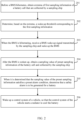
- Step 101 Before the BMS hibernates, obtain an extremum of first sampling information of a battery cell that is collected by a sampling chip, and determine, based on the extremum, a wake-up threshold corresponding to the first sampling information.
- Step 102 When the BMS is hibernating, receive a BMS wake-up signal transmitted by the sampling chip and wake up the BMS.
- the BMS wake-up signal is transmitted by the sampling chip when it is determined that a sampling value of second sampling information of the battery cell reaches the wake-up threshold, and the second sampling information of the battery cell is collected by the sampling chip when the BMS is hibernating.
- the sampling chip is provided in a battery pack. Before hibernating, the BMS is working normally.
- the BMS that is working normally may collect the first sampling information such as a first voltage or a first temperature of the battery cell in the battery pack through the sampling chip, and then determine, based on the extremum of the first sampling information of the battery cell that is collected by the sampling chip, the wake-up threshold corresponding to the first sampling information.
- the sampling chip collects the second sampling information of the battery cell, generates the BMS wake-up signal when it is determined that the sampling value of the second sampling information of the battery cell reaches the wake-up threshold, and transmits the BMS wake-up signal to the BMS. Accordingly, the BMS receives the wake-up signal and is woken up based on the wake-up signal.
- the BMS that is woken up can enter a working state again to monitor safety of a battery.
- a battery pack may have one or more sampling chips.
- each sampling chip may collect first sampling information of a battery cell, and one or more wake-up thresholds corresponding to the first sampling information collected by each sampling chip are determined based on an extremum of the first sampling information that is collected by each sampling chip.
- each sampling chip may transmit a BMS wake-up signal to the BMS and wake up the BMS when it is determined that a sampling value of second sampling information collected by the sampling chip reaches its wake-up threshold corresponding to the first sampling information collected by the sampling chip. That is, any sampling chip can wake up the BMS when the sampling value of the collected sampling information reaches the wake-up threshold. In this way, the BMS can be woken up in a timely manner by the wake-up signal, and therefore the BMS can find battery safety problems in a timely manner.
- Step 202 Determine, based on the extremum, a wake-up threshold corresponding to the first sampling information.
- the wake-up threshold is used for the sampling chip to wake up the BMS that is hibernating.
- the first sampling information includes a first sampling voltage
- the second sampling information includes a second sampling voltage
- the wake-up threshold includes a first abnormal voltage threshold
- a process for implementing step 202 may be: determining a minimum of the first sampling voltage as a first target voltage value; and determining, based on the first target voltage value and a first voltage threshold, the first abnormal voltage threshold.
- a voltage down-regulation threshold may be set based on a case that a voltage of the battery cell drops in the battery cell depolarization process.
- the voltage down-regulation threshold may be a fixed value, for example, 300 mV (millivolts).
- a voltage of the battery cell drops much, and a larger voltage down-regulation threshold may be set.
- the voltage down-regulation threshold may alternatively be an unfixed value that changes with hibernation duration of the BMS. For example, one hour before the BMS hibernates, the voltage down-regulation threshold may be set to 300 mV, and one hour after the BMS hibernates, the voltage down-regulation threshold may be set to 100 mV, 50 mV, or the like.
- the first voltage threshold may further include a battery cell undervoltage class 2 threshold.
- the difference between the first target voltage value and the voltage down-regulation threshold may be first determined, and then a larger one of the difference and the battery cell undervoltage class 2 threshold is determined as the first abnormal voltage threshold.
- Each battery pack has a different battery cell undervoltage class 2 threshold.
- one wake-up threshold (that is, the first abnormal voltage threshold) corresponding to the first sampling voltage is determined based on the minimum (that is, the first target voltage value) of the first sampling voltage and the first voltage threshold.
- the first voltage threshold is set based on a case that a voltage drops in a battery cell depolarization process, and/or a case that no battery cell undervoltage class 2 occurs in a battery cell depolarization process, and therefore is high in accuracy. In this way, accuracy of the first abnormal voltage threshold determined based on the first target voltage value and the first voltage threshold is also improved.
- the first sampling information includes a first sampling voltage
- the second sampling information includes a second sampling voltage
- the wake-up threshold includes a second abnormal voltage threshold
- a process for implementing step 202 may be: determining a maximum of the first sampling voltage as a second target voltage value; and determining, based on the second target voltage value and a second voltage threshold, the second abnormal voltage threshold.
- the second voltage threshold includes a first voltage up-regulation threshold, and when the second abnormal voltage threshold is determined based on the second target voltage value and the second voltage threshold, a sum of the second target voltage value and the first voltage up-regulation threshold may be determined as the second abnormal voltage threshold.
- the first voltage up-regulation threshold may further be set based on a case that a voltage of the battery cell rises back in the battery cell depolarization process.
- the first voltage up-regulation threshold may be a fixed value, for example, 300 mV, or may be an unfixed value that changes with hibernation duration of the BMS. For example, one hour before the BMS hibernates, the first voltage up-regulation threshold may be set to 300 mV, and one hour after the BMS hibernates, the first voltage up-regulation threshold may be set to 100 mV, 50 mV, or the like.
- a setting basis of the first voltage up-regulation threshold reference may be made to a setting basis of the voltage down-regulation threshold. Details are not described herein again.
- the second voltage threshold further includes the battery cell full charge voltage and the second voltage up-regulation threshold.
- a sum of the second target voltage value and the first voltage up-regulation threshold is first determined as a first value
- a sum of the battery cell full charge voltage and the second voltage up-regulation threshold is determined as a second value
- a smaller one of the first value and the second value is determined as the second abnormal voltage threshold
- the first voltage up-regulation threshold is an unfixed value that changes with hibernation duration of the BMS.
- the second voltage up-regulation threshold may be set based on experience, and may be set to a relatively small value, for example, 100 mV.
- another wake-up threshold (that is, the second abnormal voltage threshold) corresponding to the first sampling voltage is determined based on the maximum (that is, the second target voltage value) of the first sampling voltage and the second voltage threshold.
- the second voltage threshold is set based on a case that a voltage rises back in a battery cell depolarization process, and/or a case that a voltage of a battery cell normally does not exceed the full charge voltage plus the second voltage up-regulation threshold, and therefore is high in accuracy. Therefore, accuracy of the second abnormal voltage threshold determined based on the second target voltage value and the second voltage threshold is also improved.
- the first sampling information includes a first sampling temperature
- the second sampling information includes a second sampling temperature
- the wake-up threshold includes a first abnormal temperature threshold
- a process for implementing step 202 may be: determining a maximum of the first sampling temperature as a first target temperature value; and determining a sum of the first target temperature value and a temperature up-regulation threshold as the first abnormal temperature threshold.
- the maximum of the first sampling temperature is up-regulated by adding the temperature up-regulation threshold, to obtain the first abnormal temperature threshold. This is high in accuracy.
- the temperature up-regulation threshold may be set based on experience, for example, may be 2°C (degrees Celsius).
- step 201 it can be learned that the extremum of the first sampling information of the battery cell that is collected by each sampling chip may be determined based on the multiple pieces of first sampling information collected by the sampling chip, and step 202 actually is determining, based on the extremum of the first sampling information of the battery cell that is collected by each sampling chip, a wake-up threshold corresponding to the first sampling information collected by the sampling chip.
- step 202 of determining the wake-up threshold corresponding to the first sampling information collected by each sampling chip before hibernating, the BMS may transmit, to the corresponding sampling chip, the wake-up threshold corresponding to the sampling chip.
- each sampling chip may receive and store the wake-up threshold that is transmitted by the BMS and that corresponds to the first sampling information collected by the sampling chip. For example, if a wake-up threshold determined based on an extremum of multiple first sampling voltages that are collected by the first sampling chip is 4.1 V (volts), and a wake-up threshold determined based on an extremum of multiple first sampling voltages that are collected by the second sampling chip is 4.2 V, before hibernating, the BMS transmits the wake-up threshold 4.1 V to the first sampling chip, and transmits the wake-up threshold 4.2 V to the second sampling chip.
- the sampling chip collects a sampling value of second sampling information of the battery cell in real time under low power consumption.
- the sampling chip When it is determined that the sampling value of the second sampling information collected by the sampling chip reaches the wake-up threshold corresponding to the collected first sampling information, the sampling chip generates the BMS wake-up signal, and transmits the BMS wake-up signal to the BMS by using a pre-designed hardware circuit (or a wake-up circuit).
- the second sampling information may be a second sampling voltage, a second sampling temperature, or the like.
- the BMS wake-up signal of this application may be transmitted by the sampling chip when it is determined that the sampling value of the second sampling voltage reaches the first abnormal voltage threshold, or when it is determined that the sampling value of the second sampling chip reaches the second abnormal voltage threshold, or when the sampling value of the second sampling temperature reaches the first abnormal temperature threshold.
- the BMS wake-up signal may be transmitted when it is determined that the sampling value of the second sampling voltage is less than or equal to the first abnormal voltage threshold, or when it is determined that the sampling value of the second sampling chip is greater than or equal to the second abnormal voltage threshold, or when it is determined that the sampling value of the second sampling temperature is greater than or equal to the first abnormal temperature threshold. This is not limited in the embodiments of this application.
- a sampling chip collects multiple sampling values of second sampling voltage and multiple sampling values of second sampling temperature. If any one of the sampling values of the second sampling voltage is less than or equal to the first abnormal voltage threshold, or any one of sampling values of the second sampling voltage is greater than or equal to the second abnormal voltage threshold, or any one of the sampling values of the second sampling temperature is greater than or equal to the first abnormal temperature threshold, the sampling chip may transmit a wake-up signal to the BMS in the first sampling time, to wake up the BMS that is hibernating.
- the BMS wake-up signal of this application may further be transmitted by the sampling chip when it is determined that at least two conditions of a first condition, a second condition and a third conduction are satisfied simultaneously.
- the first condition means that the sampling value of the second sampling voltage reaches the first abnormal voltage threshold
- the second condition means that the sampling value of the second sampling chip reaches the second abnormal voltage threshold
- the third condition means that the sampling value of the second sampling temperature reaches the first abnormal temperature threshold. This is not limited in the embodiments of this application.
- Step 203 When the BMS is hibernating, receive the BMS wake-up signal transmitted by the sampling chip and wake up the BMS.
- the BMS wake-up signal is transmitted by the sampling chip when it is determined that a sampling value of second sampling information of the battery cell reaches the wake-up threshold, and the second sampling information of the battery cell is collected by the sampling chip when the BMS is hibernating.
- step 204 and step 205 are examples useful for understanding the invention.
- Step 204 After the BMS is woken up, obtain a sampling value of preset sampling information of the battery cell collected by the sampling chip.
- the preset sampling information may be a third sampling voltage, a third sampling temperature, or the like.
- the sampling chip may collect multiple sampling values of the third sampling voltage and multiple sampling values of the third sampling temperature of the battery cell in real time, and transmit, to the BMS, the multiple collected sampling values of the third sampling voltage and the multiple collected sampling values of the third sampling temperature. Accordingly, the BMS may receive the multiple sampling values of the third sampling voltage that are collected by the sampling chip and the multiple sampling values of the third sampling temperature that are collected by the sampling chip.
- Step 205 When it is determined that the sampling value of the preset sampling information satisfies a preset alarm condition, determine that a safety alarm is to be generated for a battery.
- thermal runaway voltage threshold When it is determined that thermal runaway has occurred, it is considered that a safety alarm is to be generated for the battery.
- the alarm condition may include a thermal runaway voltage threshold and a thermal runaway temperature threshold.
- the sampling value of the third sampling voltage is less than or equal to the thermal runaway voltage threshold and the sampling value of the third sampling temperature is greater than or equal to the thermal runaway temperature threshold, it may be determined that the sampling value of the preset sampling information satisfies the preset alarm condition.
- the thermal runaway voltage threshold and the thermal runaway temperature threshold may be set based on experience.
- the thermal runaway voltage threshold may be less than the first abnormal voltage threshold and the second abnormal voltage threshold.
- the thermal runaway temperature threshold may be less than the first abnormal temperature threshold.
- the sampling value of the third sampling temperature is abnormal, for example, the sampling value of the third sampling temperature is too high, or the sampling value of the third sampling temperature exhibits a temperature rise, it may also be considered that a safety alarm is to be generated for the battery.
- the alarm condition may include the second abnormal temperature threshold.
- the second abnormal temperature threshold may be set based on experience. Generally, the second abnormal temperature threshold is an unreachable high temperature, and may be greater than the first abnormal temperature threshold. Therefore, the second abnormal temperature threshold may be set to a relatively large value, for example, may be 70°C.
- a sampling value of the third sampling temperature of a sampling point collected by the sampling chip in a later time is greater than a sampling value of the third sampling temperature of the sampling point collected in a current time, it may be determined that the sampling value of the third sampling temperature exhibits a temperature rise, and therefore it may be determined that the sampling value of the preset sampling information satisfies the preset alarm condition.
- Step 206 Wake up a control system of a vehicle, so that the control system of the vehicle starts a radiator to cool the battery.
- the vehicle includes the battery.
- the BMS that is woken up may further wake up the control system of the vehicle in a CAN communication manner or other wake-up manners.
- the control system may take measures to cool the battery, so as to avoid safety accidents.
- the control system may control a system to start the radiator to cool the battery.
- the radiator may be a water pump, other thermal management components, or the like.
- the BMS that is woken up may continuously perform step 204 and step 205 for a period of time. If it is determined that the no safety alarm is to be generated for the battery in this period of time, the BMS hibernates again. Then, the steps of the BMS wake-up method according to the embodiments of this application may be performed again. Generally, the BMS that is woken up may continuously perform step 204 and step 205 for 10 minutes.
- the wake-up threshold corresponding to first sampling information is determined based on the obtained extremum of the first sampling information of the battery cell.
- the sampling chip collects the second sampling information of the battery cell when the BMS is hibernating, and transmits the wake-up signal to the BMS when it is determined that the second sampling information of the battery cell reaches the wake-up threshold. In this way, the BMS can be woken up in a timely manner by the wake-up signal, and therefore the BMS can find battery safety problems in a timely manner.
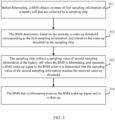
- Step 302 The BMS determines, based on the extremum, a wake-up threshold corresponding to the first sampling information, and transmits the wake-up threshold to the sampling chip.
- Step 303 The sampling chip collects a sampling value of second sampling information of the battery cell when the BMS is hibernating, and transmits a BMS wake-up signal to the BMS when it is determined that the sampling value of the second sampling information reaches the received wake-up threshold.
- Step 304 The BMS that is hibernating receives the BMS wake-up signal and is woken up.
- step 301 to step 304 For interpretation of step 301 to step 304, reference is made to related descriptions of step 201 to step 203. After the BMS is woken up, safety of the battery can be monitored. For interpretation about the BMS monitoring safety of the battery, reference is made to related descriptions of step 204 to step 206. Details are not described herein.
- the wake-up threshold corresponding to the first sampling information is determined based on the obtained extremum of the first sampling information of the battery cell.
- the sampling chip collects the second sampling information of the battery cell when the BMS is hibernating, and transmits the wake-up signal to the BMS when it is determined that the second sampling information of the battery cell reaches the wake-up threshold. In this way, the BMS can be woken up in a timely manner by the wake-up signal, and therefore the BMS can find battery safety problems in a timely manner.
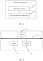
- the wake-up signal receiving module 402 is configured to receive, when the BMS is hibernating, a BMS wake-up signal transmitted by the sampling chip and wake up the BMS, where the BMS wake-up signal is transmitted by the sampling chip when it is determined that a sampling value of second sampling information of the battery cell reaches the wake-up threshold, and the second sampling information of the battery cell is collected by the sampling chip when the BMS is hibernating.
- the first sampling information includes a first sampling voltage
- the second sampling information includes a second sampling voltage
- the wake-up threshold includes a first abnormal voltage threshold
- the determining module 401 is configured to: determine a minimum of the first sampling voltage as a first target voltage value; and determine, based on the first target voltage value and a first voltage threshold, a first abnormal voltage threshold.
- the first voltage threshold includes a voltage down-regulation threshold
- the determining module 401 is configured to: determine a difference between the first target voltage value and the voltage down-regulation threshold as the first abnormal voltage threshold.
- the first voltage threshold includes a voltage down-regulation threshold and a battery cell undervoltage class 2 threshold
- the determining module 401 is configured to: determine a larger one of the battery cell undervoltage class 2 threshold and a difference between the first target voltage value and the voltage down-regulation threshold as the first abnormal voltage threshold.
- the first sampling information includes a first sampling voltage
- the second sampling information includes a second sampling voltage
- the wake-up threshold includes a second abnormal voltage threshold
- the determining module 401 is configured to: determine a maximum of the first sampling voltage as a second target voltage value; and determine, based on the second target voltage value and a second voltage threshold, a second abnormal voltage threshold.
- the second voltage threshold includes a first voltage up-regulation threshold
- the determining module 401 is configured to: determine a sum of the second target voltage value and the first voltage up-regulation threshold as the second abnormal voltage threshold.
- the second voltage threshold includes a first voltage up-regulation threshold, a battery cell full charge voltage and a second voltage up-regulation threshold, and the determining module 401 is configured to: determine a smaller one of a sum of the second target voltage value and the first voltage up-regulation threshold, and a sum of the battery cell full charge voltage and the second voltage up-regulation threshold as the second abnormal voltage threshold, wherein the first voltage up-regulation threshold is an unfixed value that changes with hibernation duration of the BMS.
- the first sampling information includes a first sampling temperature
- the second sampling information includes a second sampling temperature
- the wake-up threshold includes a first abnormal temperature threshold
- the determining module 401 is configured to: determine a maximum of the first sampling temperature as a first target temperature value; and determine a sum of the first target temperature value and a temperature up-regulation threshold as the first abnormal temperature threshold.
- the wake-up threshold corresponding to the first sampling information is determined based on the obtained extremum of the first sampling information of the battery cell.
- the sampling chip collects the second sampling information of the battery cell when the BMS is hibernating, and transmits the wake-up signal to the BMS when it is determined that the second sampling information of the battery cell reaches the wake-up threshold. In this way, the BMS can be woken up in a timely manner by the wake-up signal, and therefore the BMS can find battery safety problems in a timely manner.
- each unit may be a separate processing element, or may be integrated into a chip of the apparatus.
- each unit may alternatively be stored in a memory in a form of program for calling by a given processing element of the apparatus to implement functions of the unit.
- these units may be all or partly integrated, or may be implemented separately.
- the processing elements herein may be an integrated circuit capable of signal processing.
- all the steps of the foregoing method or all the foregoing units may be implemented through an integrated logic circuit of hardware in the processing elements, or may be implemented in a form of software called by the processing elements.
- An embodiment of this application further provides a computer-readable storage medium, where the computer-readable storage medium stores a computer program or an instruction.
- the computer program or the instruction is executed by a processor, the BMS wake-up methods according to the embodiments in FIG. 1 to FIG. 3 are implemented.
- the computer-readable storage medium may include an electronic circuit, a semiconductor memory device, a read-only memory (read-only memory, ROM), a flash memory, an erasable ROM (EROM), a floppy disk, a CD-ROM, a compact disc, a hard disk, an optical carrier, a radio frequency (RF) link, and the like. This is not limited herein.
- FIG. 5 is a schematic structural diagram of another BMS wake-up apparatus according to an example useful for understanding the invention.
- the BMS wake-up apparatus includes a processor 510, a memory 520, and an interface 530.
- the processor 510, the memory 520, and the interface 530 are connected through a bus 540.
- the bus may be implemented through a connecting circuit.
- the memory 520 is configured to store programs. When the programs are called by the processor 510, the methods executed by the BMS wake-up apparatus according to the foregoing embodiments can be implemented.
- the interface 530 is configured to communicate with another BMS wake-up apparatus.
- the interface 530 may communicate with the another BMS wake-up apparatus in a wired connection manner or a wireless connection manner.
- Functions of the units of the foregoing BMS wake-up apparatus may be implemented by calling programs stored in the memory 520 by the processor 510. That is, the foregoing BMS wake-up apparatus includes the processor 510 and the memory 520.
- the memory 520 is configured to store programs. When the programs are called by the processor 510, the methods according to the foregoing method embodiments are implemented.
- the processor 510 herein may be a general-purpose processor, or may be other processors capable of calling programs.
- the processor 510 may be configured as one or more integrated circuits to implement the methods executed by the BMS wake-up apparatus according to the foregoing embodiments, for example, one or more application specific integrated circuits (application specific integrated circuit, ASIC), one or more digital signal processors (digital signal processor, DSP), one or more field programmable gate arrays (field programmable gate array, FPGA), other programmable-logic devices, discrete gate or transistor logic devices, discrete hardware components, or the like.
- ASIC application specific integrated circuit
- DSP digital signal processor
- FPGA field programmable gate array
- the processor 510 may be a general-purpose processor, for example, a central processing unit (central processing unit, CPU), a controller, a micro-controller, a single-chip microcomputer, or other processors capable of calling programs.
- these units may be integrated, to be implemented on a system on chip.
- the number of memories 520 is not limited, and may be one or more.
- the memory 520 includes at least one type of readable storage medium.
- the readable storage medium includes a non-volatile memory (non-volatile memory) or a volatile memory, for example, a flash memory (flash memory), a hard disk, a multimedia card, a disk memory (for example, SD or DX memory), a random access memory (random access memory, RAM), a read-only memory (read-only memory, ROM), an erasable programmable read-only memory (erasable programmable read-only memory, EPROM), an electrically erasable programmable read-only memory (electrically erasable programmable read-only memory, EEPROM), a programmable read-only memory (programmable read-only memory, PROM), a magnetic memory, a magnetic disk, a compact disc, or the like.
- a non-volatile memory non-volatile memory
- volatile memory for example, a flash memory (flash memory), a hard disk, a multimedia card, a disk
- the RAM may include a static RAM or a dynamic RAM.
- the memory 520 may be an internal memory of the apparatus, for example, a hard disk or a memory of the apparatus.
- the memory 520 may alternatively be an external storage device of the apparatus, for example, a plug-in hard disk, a smart media card (smart media card, SMC), a secure digital (secure digital, SD) card, a flash card (flash card), or the like that is provided on the apparatus.
- the memory 520 may alternatively include both an internal memory of the apparatus and an external storage device of the apparatus.
- the memory 520 is generally configured to store an operating system and various application software that are installed in the apparatus, for example, program code for the BMS wake-up method.
- the memory 520 may be further configured to temporarily store various data that has been output or that is to be output.
- the bus 540 may be an industry standard architecture (industry standard architecture, ISA) bus, a peripheral component interconnect (peripheral component interconnect, PCI) bus, an extended industry standard architecture (extended industry standard architecture, EISA) bus, or the like.
- the bus 540 may include an address bus, a data bus, a control bus, or the like.
- the bus is only represented by one bold line in the figure, but this does not mean that there is only one bus or one type of bus.
- the processor 510 is configured to control overall operations of the apparatus.
- the memory 520 is configured to store program code or instructions.
- the program code includes computer operation instructions.
- the processor 510 is configured to execute the program code or instructions stored in the memory 520, or process data, for example, to run program code for the BMS wake-up method.
- the wake-up threshold corresponding to the first sampling information is determined based on the obtained extremum of the first sampling information of the battery cell.
- the sampling chip collects the second sampling information of the battery cell when the BMS is hibernating, and transmits the wake-up signal to the BMS when it is determined that the second sampling information of the battery cell reaches the wake-up threshold. In this way, the BMS can be woken up in a timely manner by the wake-up signal, and therefore the BMS can find battery safety problems in a timely manner.
Landscapes
- Engineering & Computer Science (AREA)
- Manufacturing & Machinery (AREA)
- General Chemical & Material Sciences (AREA)
- Electrochemistry (AREA)
- Chemical Kinetics & Catalysis (AREA)
- Chemical & Material Sciences (AREA)
- Power Engineering (AREA)
- Sustainable Energy (AREA)
- Mechanical Engineering (AREA)
- Transportation (AREA)
- Sustainable Development (AREA)
- Life Sciences & Earth Sciences (AREA)
- Microelectronics & Electronic Packaging (AREA)
- Physics & Mathematics (AREA)
- General Physics & Mathematics (AREA)
- Secondary Cells (AREA)
Claims (3)
- Un procédé de réveil de BMS, caractérisé en ce que le procédé comprend:avant qu'un système de gestion de batterie BMS ne soit en hibernation, l'obtention d'un extremum de premières données d'échantillonnage d'une cellule de batterie qui sont collectées par une puce d'échantillonnage, et la détermination, sur la base de l'extremum, d'un seuil de réveil correspondant aux premières données d'échantillonnage, dans lequel le seuil de réveil est utilisé pour que la puce d'échantillonnage réveille le BMS qui est en hibernation; etlorsque le BMS est en hibernation, la réception d'un signal de réveil du BMS transmis par la puce d'échantillonnage et le réveil du BMS, dans lequel le signal de réveil du BMS est transmis par la puce d'échantillonnage lorsqu'il est déterminé qu'une valeur d'échantillonnage des deuxièmes données d'échantillonnage de la cellule de batterie atteint le seuil de réveil, et les deuxièmes données d'échantillonnage de la cellule de batterie sont collectées par la puce d'échantillonnage lorsque le BMS est en hibernation;
dans lequel
les premières données d'échantillonnage comprennent une première tension d'échantillonnage, les deuxièmes données d'échantillonnage comprennent une deuxième tension d'échantillonnage, le seuil de réveil comprend un deuxième seuil de tension anormal, et la détermination, sur la base de l'extremum, d'un seuil de réveil correspondant aux premières données d'échantillonnage comprend:la détermination d'une valeur maximum de la première tension d'échantillonnage en tant que deuxième valeur de tension cible; etla détermination, sur la base de la deuxième valeur de tension cible et d'un deuxième seuil de tension, du deuxième seuil de tension anormal, dans lequel le deuxième seuil de tension comprend un premier seuil de régulation à la hausse de tension, une tension de charge complète de cellule de batterie et un deuxième seuil de régulation à la hausse de tension, et la détermination, sur la base de la deuxième valeur de tension cible et d'un deuxième seuil de tension, du deuxième seuil de tension anormal comprend:la détermination de la plus petite valeur d'une somme de la deuxième valeur de tension cible et du premier seuil de régulation à la hausse de tension, et une somme de la tension de charge complète de cellule de batterie et du deuxième seuil de régulation à la hausse de tension en tant que deuxième seuil de tension anormal;dans lequel le premier seuil de régulation à la hausse de tension est une valeur non fixée qui change avec la durée d'hibernation du BMS. - Un appareil de réveil de BMS, caractérisé en ce que l'appareil comprend:un module de détermination (401), configuré pour obtenir, avant qu'un système de gestion de batterie BMS ne soit en hibernation, un extremum de premières données d'échantillonnage d'une cellule de batterie qui sont collectées par une puce d'échantillonnage, et la détermination, sur la base de l'extremum, d'un seuil de réveil correspondant aux premières données d'échantillonnage, dans lequel le seuil de réveil est utilisé pour que la puce d'échantillonnage réveille le BMS qui est en hibernation; etun module de réception de signal de réveil (402), configuré pour recevoir, lorsque le BMS est en hibernation, un signal de réveil du BMS transmis par la puce d'échantillonnage et réveiller le BMS, dans lequel le signal de réveil du BMS est transmis par la puce d'échantillonnage lorsqu'il est déterminé qu'une valeur d'échantillonnage des deuxièmes données d'échantillonnage de la cellule de batterie atteint le seuil de réveil, et les deuxièmes données d'échantillonnage de la cellule de batterie sont collectées par la puce d'échantillonnage lorsque le BMS est en hibernation;caractérisé en ce que les premières données d'échantillonnage comprennent une première tension d'échantillonnage, les deuxièmes données d'échantillonnage comprennent une deuxième tension d'échantillonnage, le seuil de réveil comprend un deuxième seuil de tension anormal, et le module de détermination (401) est configuré pour:déterminer une valeur maximum de la première tension d'échantillonnage en tant que deuxième valeur de tension cible; etdéterminer, sur la base de la deuxième valeur de tension cible et d'un deuxième seuil de tension, le deuxième seuil de tension anormal;
dans lequel
le deuxième seuil de tension comprend un premier seuil de régulation à la hausse de tension, une tension de charge complète de cellule de batterie et un deuxième seuil de régulation à la hausse de tension, et le module de détermination (401) est configuré pour:déterminer la plus petite valeur d'une somme de la deuxième valeur de tension cible et du premier seuil de régulation à la hausse de tension, et une somme de la tension de charge complète de cellule de batterie et du deuxième seuil de régulation à la hausse de tension en tant que deuxième seuil de tension anormal;dans lequel le premier seuil de régulation à la hausse de tension est une valeur non fixée qui change avec la durée d'hibernation du BMS. - Un support de stockage lisible par ordinateur qui stocke un programme informatique, caractérisé en ce que, lorsque le programme informatique est exécuté par un processeur, le procédé de réveil du BMS selon la revendication 1 est mis en oeuvre.
Applications Claiming Priority (1)
| Application Number | Priority Date | Filing Date | Title |
|---|---|---|---|
| PCT/CN2021/106358 WO2023283846A1 (fr) | 2021-07-14 | 2021-07-14 | Procédé et appareil de réveil de bms et support de stockage |
Publications (3)
| Publication Number | Publication Date |
|---|---|
| EP4144575A1 EP4144575A1 (fr) | 2023-03-08 |
| EP4144575A4 EP4144575A4 (fr) | 2023-03-08 |
| EP4144575B1 true EP4144575B1 (fr) | 2024-12-11 |
Family
ID=84890864
Family Applications (1)
| Application Number | Title | Priority Date | Filing Date |
|---|---|---|---|
| EP21904621.6A Active EP4144575B1 (fr) | 2021-07-14 | 2021-07-14 | Procédé et appareil de réveil de bms et support de stockage |
Country Status (4)
| Country | Link |
|---|---|
| US (1) | US11817563B2 (fr) |
| EP (1) | EP4144575B1 (fr) |
| CN (1) | CN116419865A (fr) |
| WO (1) | WO2023283846A1 (fr) |
Families Citing this family (5)
| Publication number | Priority date | Publication date | Assignee | Title |
|---|---|---|---|---|
| CN116101126A (zh) * | 2023-03-07 | 2023-05-12 | 珠海冠宇动力电源有限公司 | 电池系统及汽车 |
| CN116184255B (zh) * | 2023-04-27 | 2023-08-01 | 南京芯驰半导体科技有限公司 | 一种测试芯片内部电源的瞬态响应的方法和控制系统 |
| CN117021954B (zh) * | 2023-08-23 | 2026-04-17 | 荷尖睿联(西安)智能科技有限公司 | 基于车辆bms通讯的车库主动防护系统及方法 |
| CN117134470B (zh) * | 2023-10-26 | 2024-02-13 | 珠海市嘉德电能科技有限公司 | Bms电池管理系统的休眠控制方法及相关装置 |
| CN120565868B (zh) * | 2025-07-29 | 2025-10-10 | 宁德时代新能源科技股份有限公司 | 电池管理系统、电池系统及电池驱动设备 |
Citations (1)
| Publication number | Priority date | Publication date | Assignee | Title |
|---|---|---|---|---|
| CN112026589A (zh) * | 2019-11-28 | 2020-12-04 | 长城汽车股份有限公司 | 一种电池包控制方法、系统及车辆 |
Family Cites Families (7)
| Publication number | Priority date | Publication date | Assignee | Title |
|---|---|---|---|---|
| US20120249055A1 (en) * | 2011-03-29 | 2012-10-04 | GRRREEN, Inc., a Delaware corporation | Individual cell charger and method of using same |
| CN111942217A (zh) * | 2019-04-29 | 2020-11-17 | 广州汽车集团股份有限公司 | 一种电池监控方法、装置、系统及车辆 |
| US11830990B2 (en) * | 2020-01-27 | 2023-11-28 | GM Global Technology Operations LLC | Two-level method for thermal runaway detection |
| CN111463873A (zh) * | 2020-06-22 | 2020-07-28 | 江苏时代新能源科技有限公司 | 电池监测方法、电池管理系统以及电池管理设备 |
| CN113036250B (zh) * | 2021-02-27 | 2022-11-18 | 重庆长安新能源汽车科技有限公司 | 一种动力电池热失控全时段监控系统、方法及新能源汽车 |
| CN112977160B (zh) * | 2021-04-06 | 2023-01-06 | 广汽埃安新能源汽车有限公司 | 电池管理方法、电池系统、车辆及计算机存储介质 |
| CN113043912A (zh) * | 2021-04-06 | 2021-06-29 | 广州汽车集团股份有限公司 | 一种电池全时检测装置、系统及汽车 |
-
2021
- 2021-07-14 CN CN202180073940.1A patent/CN116419865A/zh active Pending
- 2021-07-14 EP EP21904621.6A patent/EP4144575B1/fr active Active
- 2021-07-14 WO PCT/CN2021/106358 patent/WO2023283846A1/fr not_active Ceased
-
2022
- 2022-07-14 US US17/864,676 patent/US11817563B2/en active Active
Patent Citations (2)
| Publication number | Priority date | Publication date | Assignee | Title |
|---|---|---|---|---|
| CN112026589A (zh) * | 2019-11-28 | 2020-12-04 | 长城汽车股份有限公司 | 一种电池包控制方法、系统及车辆 |
| US20220340012A1 (en) * | 2019-11-28 | 2022-10-27 | Great Wall Motor Company Limited | Battery pack control method and system, and vehicle |
Also Published As
| Publication number | Publication date |
|---|---|
| WO2023283846A1 (fr) | 2023-01-19 |
| US20230020775A1 (en) | 2023-01-19 |
| EP4144575A1 (fr) | 2023-03-08 |
| US11817563B2 (en) | 2023-11-14 |
| CN116419865A (zh) | 2023-07-11 |
Similar Documents
| Publication | Publication Date | Title |
|---|---|---|
| EP4144575B1 (fr) | Procédé et appareil de réveil de bms et support de stockage | |
| US12545146B2 (en) | Method and system for heat preservation of battery of vehicle, storage medium and processor | |
| CN111114328A (zh) | 一种电动汽车动力蓄电池热失控预警方法、装置及系统 | |
| US20250206186A1 (en) | Battery pack equalization method and apparatus, vehicle, and storage medium | |
| US9789784B2 (en) | Maintaining a vehicle battery | |
| US20190296575A1 (en) | Solar battery system and control method thereof | |
| EP4286209A1 (fr) | Appareil et procédé de réveil de réapprovisionnement en énergie pour batterie basse tension | |
| CN111251943B (zh) | 一种电池组的均衡方法及装置 | |
| US12253572B2 (en) | Battery diagnosing apparatus and method | |
| CN111308357A (zh) | 电池容量估算方法、电池管理系统、车辆及存储介质 | |
| CN113910980A (zh) | 电芯故障监控系统及方法 | |
| CN113844335A (zh) | 车载电池的充电方法、车辆和可读存储介质 | |
| CN111044912A (zh) | 休眠监测系统和方法 | |
| CN107933337A (zh) | 电动汽车及其电池管理系统 | |
| US12451715B2 (en) | Battery, electric apparatus, and charging method and apparatus for battery | |
| CN120135005A (zh) | 电池休眠均衡功能的管理方法、装置、车辆及介质 | |
| WO2025077761A1 (fr) | Procédé d'interaction de données pour système de gestion de batterie, et système de gestion de batterie | |
| CN119199555A (zh) | 一种基于积分运算的电池寿命预测方法、装置及存储介质 | |
| CN116620101A (zh) | 一种电池检测方法、装置、设备及存储介质 | |
| CN111976539B (zh) | 确定电池的电压变化率的方法、装置、介质及设备 | |
| CN117148166A (zh) | 电池安全等级预测方法、装置、计算机设备及存储介质 | |
| CN116648370A (zh) | 用于管理电池的装置和用于控制电池的方法 | |
| CN120065037A (zh) | 热失控检测方法、电子装置、电池、车辆、介质及产品 | |
| CN118671612A (zh) | 热失控风险检测方法、车辆、设备、存储介质及程序产品 | |
| CN121340998A (zh) | 车辆蓄电池的能量管理方法及装置 |
Legal Events
| Date | Code | Title | Description |
|---|---|---|---|
| STAA | Information on the status of an ep patent application or granted ep patent |
Free format text: STATUS: UNKNOWN |
|
| STAA | Information on the status of an ep patent application or granted ep patent |
Free format text: STATUS: THE INTERNATIONAL PUBLICATION HAS BEEN MADE |
|
| PUAI | Public reference made under article 153(3) epc to a published international application that has entered the european phase |
Free format text: ORIGINAL CODE: 0009012 |
|
| STAA | Information on the status of an ep patent application or granted ep patent |
Free format text: STATUS: REQUEST FOR EXAMINATION WAS MADE |
|
| STAA | Information on the status of an ep patent application or granted ep patent |
Free format text: STATUS: EXAMINATION IS IN PROGRESS |
|
| 17P | Request for examination filed |
Effective date: 20220621 |
|
| A4 | Supplementary search report drawn up and despatched |
Effective date: 20221220 |
|
| AK | Designated contracting states |
Kind code of ref document: A1 Designated state(s): AL AT BE BG CH CY CZ DE DK EE ES FI FR GB GR HR HU IE IS IT LI LT LU LV MC MK MT NL NO PL PT RO RS SE SI SK SM TR |
|
| 17Q | First examination report despatched |
Effective date: 20230216 |
|
| RAP1 | Party data changed (applicant data changed or rights of an application transferred) |
Owner name: CONTEMPORARY AMPEREX TECHNOLOGY(HONG KONG) LIMITED |
|
| GRAP | Despatch of communication of intention to grant a patent |
Free format text: ORIGINAL CODE: EPIDOSNIGR1 |
|
| STAA | Information on the status of an ep patent application or granted ep patent |
Free format text: STATUS: GRANT OF PATENT IS INTENDED |
|
| DAV | Request for validation of the european patent (deleted) | ||
| DAX | Request for extension of the european patent (deleted) | ||
| GRAS | Grant fee paid |
Free format text: ORIGINAL CODE: EPIDOSNIGR3 |
|
| INTG | Intention to grant announced |
Effective date: 20241008 |
|
| GRAA | (expected) grant |
Free format text: ORIGINAL CODE: 0009210 |
|
| STAA | Information on the status of an ep patent application or granted ep patent |
Free format text: STATUS: THE PATENT HAS BEEN GRANTED |
|
| AK | Designated contracting states |
Kind code of ref document: B1 Designated state(s): AL AT BE BG CH CY CZ DE DK EE ES FI FR GB GR HR HU IE IS IT LI LT LU LV MC MK MT NL NO PL PT RO RS SE SI SK SM TR |
|
| REG | Reference to a national code |
Ref country code: GB Ref legal event code: FG4D |
|
| REG | Reference to a national code |
Ref country code: CH Ref legal event code: EP |
|
| REG | Reference to a national code |
Ref country code: DE Ref legal event code: R096 Ref document number: 602021023396 Country of ref document: DE |
|
| REG | Reference to a national code |
Ref country code: IE Ref legal event code: FG4D |
|
| P01 | Opt-out of the competence of the unified patent court (upc) registered |
Free format text: CASE NUMBER: APP_1306/2025 Effective date: 20250109 |
|
| REG | Reference to a national code |
Ref country code: LT Ref legal event code: MG9D |
|
| PG25 | Lapsed in a contracting state [announced via postgrant information from national office to epo] |
Ref country code: HR Free format text: LAPSE BECAUSE OF FAILURE TO SUBMIT A TRANSLATION OF THE DESCRIPTION OR TO PAY THE FEE WITHIN THE PRESCRIBED TIME-LIMIT Effective date: 20241211 |
|
| PG25 | Lapsed in a contracting state [announced via postgrant information from national office to epo] |
Ref country code: FI Free format text: LAPSE BECAUSE OF FAILURE TO SUBMIT A TRANSLATION OF THE DESCRIPTION OR TO PAY THE FEE WITHIN THE PRESCRIBED TIME-LIMIT Effective date: 20241211 |
|
| PG25 | Lapsed in a contracting state [announced via postgrant information from national office to epo] |
Ref country code: BG Free format text: LAPSE BECAUSE OF FAILURE TO SUBMIT A TRANSLATION OF THE DESCRIPTION OR TO PAY THE FEE WITHIN THE PRESCRIBED TIME-LIMIT Effective date: 20241211 |
|
| REG | Reference to a national code |
Ref country code: NL Ref legal event code: MP Effective date: 20241211 |
|
| PG25 | Lapsed in a contracting state [announced via postgrant information from national office to epo] |
Ref country code: ES Free format text: LAPSE BECAUSE OF FAILURE TO SUBMIT A TRANSLATION OF THE DESCRIPTION OR TO PAY THE FEE WITHIN THE PRESCRIBED TIME-LIMIT Effective date: 20241211 |
|
| PG25 | Lapsed in a contracting state [announced via postgrant information from national office to epo] |
Ref country code: LV Free format text: LAPSE BECAUSE OF FAILURE TO SUBMIT A TRANSLATION OF THE DESCRIPTION OR TO PAY THE FEE WITHIN THE PRESCRIBED TIME-LIMIT Effective date: 20241211 Ref country code: GR Free format text: LAPSE BECAUSE OF FAILURE TO SUBMIT A TRANSLATION OF THE DESCRIPTION OR TO PAY THE FEE WITHIN THE PRESCRIBED TIME-LIMIT Effective date: 20250312 |
|
| PG25 | Lapsed in a contracting state [announced via postgrant information from national office to epo] |
Ref country code: RS Free format text: LAPSE BECAUSE OF FAILURE TO SUBMIT A TRANSLATION OF THE DESCRIPTION OR TO PAY THE FEE WITHIN THE PRESCRIBED TIME-LIMIT Effective date: 20250311 |
|
| PG25 | Lapsed in a contracting state [announced via postgrant information from national office to epo] |
Ref country code: NL Free format text: LAPSE BECAUSE OF FAILURE TO SUBMIT A TRANSLATION OF THE DESCRIPTION OR TO PAY THE FEE WITHIN THE PRESCRIBED TIME-LIMIT Effective date: 20241211 |
|
| REG | Reference to a national code |
Ref country code: AT Ref legal event code: MK05 Ref document number: 1750155 Country of ref document: AT Kind code of ref document: T Effective date: 20241211 |
|
| PG25 | Lapsed in a contracting state [announced via postgrant information from national office to epo] |
Ref country code: SM Free format text: LAPSE BECAUSE OF FAILURE TO SUBMIT A TRANSLATION OF THE DESCRIPTION OR TO PAY THE FEE WITHIN THE PRESCRIBED TIME-LIMIT Effective date: 20241211 |
|
| PG25 | Lapsed in a contracting state [announced via postgrant information from national office to epo] |
Ref country code: PL Free format text: LAPSE BECAUSE OF FAILURE TO SUBMIT A TRANSLATION OF THE DESCRIPTION OR TO PAY THE FEE WITHIN THE PRESCRIBED TIME-LIMIT Effective date: 20241211 |
|
| PG25 | Lapsed in a contracting state [announced via postgrant information from national office to epo] |
Ref country code: IS Free format text: LAPSE BECAUSE OF FAILURE TO SUBMIT A TRANSLATION OF THE DESCRIPTION OR TO PAY THE FEE WITHIN THE PRESCRIBED TIME-LIMIT Effective date: 20250411 |
|
| PG25 | Lapsed in a contracting state [announced via postgrant information from national office to epo] |
Ref country code: PT Free format text: LAPSE BECAUSE OF FAILURE TO SUBMIT A TRANSLATION OF THE DESCRIPTION OR TO PAY THE FEE WITHIN THE PRESCRIBED TIME-LIMIT Effective date: 20250411 |
|
| PG25 | Lapsed in a contracting state [announced via postgrant information from national office to epo] |
Ref country code: EE Free format text: LAPSE BECAUSE OF FAILURE TO SUBMIT A TRANSLATION OF THE DESCRIPTION OR TO PAY THE FEE WITHIN THE PRESCRIBED TIME-LIMIT Effective date: 20241211 |
|
| PG25 | Lapsed in a contracting state [announced via postgrant information from national office to epo] |
Ref country code: RO Free format text: LAPSE BECAUSE OF FAILURE TO SUBMIT A TRANSLATION OF THE DESCRIPTION OR TO PAY THE FEE WITHIN THE PRESCRIBED TIME-LIMIT Effective date: 20241211 Ref country code: AT Free format text: LAPSE BECAUSE OF FAILURE TO SUBMIT A TRANSLATION OF THE DESCRIPTION OR TO PAY THE FEE WITHIN THE PRESCRIBED TIME-LIMIT Effective date: 20241211 |
|
| PG25 | Lapsed in a contracting state [announced via postgrant information from national office to epo] |
Ref country code: SK Free format text: LAPSE BECAUSE OF FAILURE TO SUBMIT A TRANSLATION OF THE DESCRIPTION OR TO PAY THE FEE WITHIN THE PRESCRIBED TIME-LIMIT Effective date: 20241211 |
|
| PG25 | Lapsed in a contracting state [announced via postgrant information from national office to epo] |
Ref country code: CZ Free format text: LAPSE BECAUSE OF FAILURE TO SUBMIT A TRANSLATION OF THE DESCRIPTION OR TO PAY THE FEE WITHIN THE PRESCRIBED TIME-LIMIT Effective date: 20241211 |
|
| PG25 | Lapsed in a contracting state [announced via postgrant information from national office to epo] |
Ref country code: IT Free format text: LAPSE BECAUSE OF FAILURE TO SUBMIT A TRANSLATION OF THE DESCRIPTION OR TO PAY THE FEE WITHIN THE PRESCRIBED TIME-LIMIT Effective date: 20241211 |
|
| PG25 | Lapsed in a contracting state [announced via postgrant information from national office to epo] |
Ref country code: SE Free format text: LAPSE BECAUSE OF FAILURE TO SUBMIT A TRANSLATION OF THE DESCRIPTION OR TO PAY THE FEE WITHIN THE PRESCRIBED TIME-LIMIT Effective date: 20241211 |
|
| REG | Reference to a national code |
Ref country code: DE Ref legal event code: R097 Ref document number: 602021023396 Country of ref document: DE |
|
| PG25 | Lapsed in a contracting state [announced via postgrant information from national office to epo] |
Ref country code: DK Free format text: LAPSE BECAUSE OF FAILURE TO SUBMIT A TRANSLATION OF THE DESCRIPTION OR TO PAY THE FEE WITHIN THE PRESCRIBED TIME-LIMIT Effective date: 20241211 |
|
| PGFP | Annual fee paid to national office [announced via postgrant information from national office to epo] |
Ref country code: DE Payment date: 20250724 Year of fee payment: 5 |
|
| PGFP | Annual fee paid to national office [announced via postgrant information from national office to epo] |
Ref country code: NO Payment date: 20250723 Year of fee payment: 5 |
|
| PGFP | Annual fee paid to national office [announced via postgrant information from national office to epo] |
Ref country code: GB Payment date: 20250722 Year of fee payment: 5 |
|
| PLBE | No opposition filed within time limit |
Free format text: ORIGINAL CODE: 0009261 |
|
| STAA | Information on the status of an ep patent application or granted ep patent |
Free format text: STATUS: NO OPPOSITION FILED WITHIN TIME LIMIT |
|
| PGFP | Annual fee paid to national office [announced via postgrant information from national office to epo] |
Ref country code: FR Payment date: 20250722 Year of fee payment: 5 |
|
| REG | Reference to a national code |
Ref country code: CH Ref legal event code: L10 Free format text: ST27 STATUS EVENT CODE: U-0-0-L10-L00 (AS PROVIDED BY THE NATIONAL OFFICE) Effective date: 20251022 |
|
| 26N | No opposition filed |
Effective date: 20250912 |
|
| REG | Reference to a national code |
Ref country code: CH Ref legal event code: H13 Free format text: ST27 STATUS EVENT CODE: U-0-0-H10-H13 (AS PROVIDED BY THE NATIONAL OFFICE) Effective date: 20260224 |
|
| PG25 | Lapsed in a contracting state [announced via postgrant information from national office to epo] |
Ref country code: LU Free format text: LAPSE BECAUSE OF NON-PAYMENT OF DUE FEES Effective date: 20250714 |
|
| REG | Reference to a national code |
Ref country code: BE Ref legal event code: MM Effective date: 20250731 |
|
| PG25 | Lapsed in a contracting state [announced via postgrant information from national office to epo] |
Ref country code: BE Free format text: LAPSE BECAUSE OF NON-PAYMENT OF DUE FEES Effective date: 20250731 |
|
| PG25 | Lapsed in a contracting state [announced via postgrant information from national office to epo] |
Ref country code: CH Free format text: LAPSE BECAUSE OF NON-PAYMENT OF DUE FEES Effective date: 20250731 |