EP4144600B1 - Adapter für reinigungssystem - Google Patents
Adapter für reinigungssystem Download PDFInfo
- Publication number
- EP4144600B1 EP4144600B1 EP22191790.9A EP22191790A EP4144600B1 EP 4144600 B1 EP4144600 B1 EP 4144600B1 EP 22191790 A EP22191790 A EP 22191790A EP 4144600 B1 EP4144600 B1 EP 4144600B1
- Authority
- EP
- European Patent Office
- Prior art keywords
- adapter
- wall
- upper wall
- side wall
- arm
- Prior art date
- Legal status (The legal status is an assumption and is not a legal conclusion. Google has not performed a legal analysis and makes no representation as to the accuracy of the status listed.)
- Active
Links
Images


Classifications
-
- B—PERFORMING OPERATIONS; TRANSPORTING
- B60—VEHICLES IN GENERAL
- B60S—SERVICING, CLEANING, REPAIRING, SUPPORTING, LIFTING, OR MANOEUVRING OF VEHICLES, NOT OTHERWISE PROVIDED FOR
- B60S1/00—Cleaning of vehicles
- B60S1/02—Cleaning windscreens, windows or optical devices
- B60S1/04—Wipers or the like, e.g. scrapers
- B60S1/32—Wipers or the like, e.g. scrapers characterised by constructional features of wiper blade arms or blades
- B60S1/40—Connections between blades and arms
-
- B—PERFORMING OPERATIONS; TRANSPORTING
- B60—VEHICLES IN GENERAL
- B60S—SERVICING, CLEANING, REPAIRING, SUPPORTING, LIFTING, OR MANOEUVRING OF VEHICLES, NOT OTHERWISE PROVIDED FOR
- B60S1/00—Cleaning of vehicles
- B60S1/02—Cleaning windscreens, windows or optical devices
- B60S1/04—Wipers or the like, e.g. scrapers
- B60S1/0408—Means for influencing the aerodynamic quality of wipers, e.g. clip-on wind deflectors
-
- B—PERFORMING OPERATIONS; TRANSPORTING
- B60—VEHICLES IN GENERAL
- B60S—SERVICING, CLEANING, REPAIRING, SUPPORTING, LIFTING, OR MANOEUVRING OF VEHICLES, NOT OTHERWISE PROVIDED FOR
- B60S1/00—Cleaning of vehicles
- B60S1/02—Cleaning windscreens, windows or optical devices
- B60S1/04—Wipers or the like, e.g. scrapers
- B60S1/32—Wipers or the like, e.g. scrapers characterised by constructional features of wiper blade arms or blades
- B60S1/34—Wiper arms; Mountings therefor
-
- B—PERFORMING OPERATIONS; TRANSPORTING
- B60—VEHICLES IN GENERAL
- B60S—SERVICING, CLEANING, REPAIRING, SUPPORTING, LIFTING, OR MANOEUVRING OF VEHICLES, NOT OTHERWISE PROVIDED FOR
- B60S1/00—Cleaning of vehicles
- B60S1/02—Cleaning windscreens, windows or optical devices
- B60S1/04—Wipers or the like, e.g. scrapers
- B60S1/32—Wipers or the like, e.g. scrapers characterised by constructional features of wiper blade arms or blades
- B60S1/38—Wiper blades
-
- B—PERFORMING OPERATIONS; TRANSPORTING
- B60—VEHICLES IN GENERAL
- B60S—SERVICING, CLEANING, REPAIRING, SUPPORTING, LIFTING, OR MANOEUVRING OF VEHICLES, NOT OTHERWISE PROVIDED FOR
- B60S1/00—Cleaning of vehicles
- B60S1/02—Cleaning windscreens, windows or optical devices
- B60S1/04—Wipers or the like, e.g. scrapers
- B60S1/32—Wipers or the like, e.g. scrapers characterised by constructional features of wiper blade arms or blades
- B60S1/38—Wiper blades
- B60S1/3848—Flat-type wiper blade, i.e. without harness
- B60S1/3849—Connectors therefor; Connection to wiper arm; Attached to blade
-
- B—PERFORMING OPERATIONS; TRANSPORTING
- B60—VEHICLES IN GENERAL
- B60S—SERVICING, CLEANING, REPAIRING, SUPPORTING, LIFTING, OR MANOEUVRING OF VEHICLES, NOT OTHERWISE PROVIDED FOR
- B60S1/00—Cleaning of vehicles
- B60S1/02—Cleaning windscreens, windows or optical devices
- B60S1/04—Wipers or the like, e.g. scrapers
- B60S1/32—Wipers or the like, e.g. scrapers characterised by constructional features of wiper blade arms or blades
- B60S1/40—Connections between blades and arms
- B60S1/4038—Connections between blades and arms for arms provided with a channel-shaped end
- B60S1/4045—Connections between blades and arms for arms provided with a channel-shaped end comprising a detachable intermediate element mounted on the channel-shaped end
- B60S1/4048—Connections between blades and arms for arms provided with a channel-shaped end comprising a detachable intermediate element mounted on the channel-shaped end the element being provided with retention means co-operating with the channel-shaped end of the arm
-
- B—PERFORMING OPERATIONS; TRANSPORTING
- B60—VEHICLES IN GENERAL
- B60S—SERVICING, CLEANING, REPAIRING, SUPPORTING, LIFTING, OR MANOEUVRING OF VEHICLES, NOT OTHERWISE PROVIDED FOR
- B60S1/00—Cleaning of vehicles
- B60S1/02—Cleaning windscreens, windows or optical devices
- B60S1/04—Wipers or the like, e.g. scrapers
- B60S1/32—Wipers or the like, e.g. scrapers characterised by constructional features of wiper blade arms or blades
- B60S1/40—Connections between blades and arms
- B60S1/4083—Connections between blades and arms for arms provided with a flat end
-
- B—PERFORMING OPERATIONS; TRANSPORTING
- B60—VEHICLES IN GENERAL
- B60S—SERVICING, CLEANING, REPAIRING, SUPPORTING, LIFTING, OR MANOEUVRING OF VEHICLES, NOT OTHERWISE PROVIDED FOR
- B60S1/00—Cleaning of vehicles
- B60S1/02—Cleaning windscreens, windows or optical devices
- B60S1/04—Wipers or the like, e.g. scrapers
- B60S1/32—Wipers or the like, e.g. scrapers characterised by constructional features of wiper blade arms or blades
- B60S1/40—Connections between blades and arms
- B60S1/4083—Connections between blades and arms for arms provided with a flat end
- B60S1/4087—Connections between blades and arms for arms provided with a flat end the end being provided with protrusions or holes
Definitions
- the present invention has as its main object an adapter for fixing a wiper blade to an arm of a wiping system, the adapter extending along a longitudinal direction, the adapter being configured to be rotatably mounted on a connector of a wiper blade about an axis of rotation transverse to the longitudinal direction, the adapter comprising at least one side wall and an upper wall having at least one common edge between them, the side wall and the upper wall participating in defining an internal volume of the adapter, the adapter comprising a first internal wall and a second internal wall extending at least partly into the internal volume of the adapter and participating in delimiting at least partly a receiving zone intended to receive the connector, the adapter comprising at least one receiving housing intended to receive the arm of the wiping system and which has a rectangular section defined by two long sides and two short sides, a straight line passing through one of the long sides intersects the receiving zone intended to receive the connector, the adapter being characterized in that it comprises at least one reinforcement (52) extending between the first internal wall (20) and the side
- the wiper blade and the arm are part of a vehicle wiping system intended to clean at least part of a glass surface of said vehicle.
- the wiping system then comprises the arm driven in rotation by an electric motor of the vehicle and ensuring the rotational movement of the wiper blade, to which it is secured via the adapter and the connector, against the glass surface so that the blade carried by the wiper blade clears said glass surface of raindrops and/or solid debris deposited on the latter.
- the receiving housing extends into the internal volume of the adapter such that the straight line passing through one of the long sides of the receiving housing also extends into the receiving area. It is understood that the straight line extends at least in part of the receiving area without however crossing said receiving area along a main dimension.
- the receiving area is delimited transversely by the first internal wall and by the second internal wall, longitudinally by two side walls and finally vertically by the upper wall and by a mouth delimited by a free edge of the internal walls and the side walls. It is understood here that the straight line thus passes through the receiving area defined by all the components delimiting the receiving area.
- the straight line passing through one of the long sides intersects the axis of rotation of the adapter within the receiving zone.
- the side wall and the top wall each have a free edge and an edge common to the side wall and the top wall
- the adapter having a triangular section seen in a cutting plane perpendicular to the longitudinal direction and defined by the free edge of the side wall, the free edge of the top wall and by the common edge between the side wall and the top wall, the top wall being curved between the common edge and its free edge seen in the cutting plane perpendicular to the longitudinal direction.
- the free edge of the upper wall corresponds to the edge arranged across the air flow when the wiping system is arranged on the vehicle, the air flow licking the upper wall.
- the free edge of the upper wall is the most forward edge of the vehicle when the wiping system is mounted on said vehicle. It is thus understood that the free edge of the side wall and the side wall itself are arranged at the rear of the wiping system, between the glazed surface and the free edge of the upper wall following a trajectory of the air flow, when the wiping system is mounted on the vehicle.
- the adapter comprises at least one reinforcement extending between the first internal wall and the side wall and/or the upper wall, the receiving housing being defined by a first portion comprising a sleeve, for example a second portion open onto the internal volume and by a third portion comprising an opening made in the reinforcement.
- the opening in the reinforcement generally takes a shape similar to a section of the sleeve viewed in a plane perpendicular to the longitudinal direction. Furthermore, the opening in the reinforcement and the sleeve are aligned along a direction parallel to the longitudinal direction.
- the reinforcement extends perpendicularly to the first internal wall and/or to the side wall.
- the receiving area is for example delimited by the first internal wall and by the second internal wall extending distinctly and parallel to the first internal wall.
- the receiving housing is laterally offset relative to the receiving area. This lateral offset optimizes the compactness of the adapter mentioned above.
- a position of the receiving housing is offset relative to a position of the receiving area in a transverse direction, the latter being perpendicular to the longitudinal direction.
- the receiving housing is arranged in the internal volume between the receiving area and the side wall.
- the straight line passing through one of the long sides intersects the axis of rotation of the adapter at an angle of between 20 and 60°, preferably between 30 and 50° and even more preferably between 35 and 45°.
- the adapter comprises a locking device intended to longitudinally secure the adapter relative to the arm of the wiping system, the locking device comprising at least one thrust member and one blocking member, the thrust member being inscribed in a profile of the upper wall while the blocking member extends at least partly into the receiving housing intended to receive the arm.
- the invention also relates to a connection device for a wiper blade comprising at least one connector and an adapter according to any one of the preceding characteristics, the connector being mounted in rotation about the axis of rotation of the adapter by means of a rotation device.
- the invention also relates to a wiper blade comprising at least one connection device according to any one of the preceding characteristics or an adapter according to any one of the preceding characteristics.
- the invention finally relates to a wiping system comprising at least one arm and a wiper blade according to any one of the preceding claims, the arm comprising at least one rod housed in the receiving housing of the adapter.
- the term "rod” is understood to mean a solid and elongated element having, for example, a rectangular section seen in a plane perpendicular to a direction of main elongation of the rod.
- At least one end of the rod takes a shape complementary to the housing for receiving the adapter, the rod having a notch cooperating with a locking device to longitudinally block the position of the adapter on the rod.
- a longitudinal direction corresponds to a main direction of elongation of an adapter according to the invention, this longitudinal direction being parallel to a longitudinal axis L of a reference L, V, T illustrated in the figures.
- a transverse direction corresponds to a direction along which a reinforcement mainly extends, this transverse direction being parallel to a transverse axis T of the reference L, V, T and this transverse axis T being perpendicular to the longitudinal axis L.
- a vertical direction corresponds to a direction parallel to a vertical axis V of the reference L, V, T, this vertical axis V being perpendicular to the longitudinal axis L and the transverse axis T.
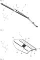
- FIG. 1 illustrates a wiping system 6 configured to ensure the cleaning of a glass surface of a vehicle, for example a windshield, so as to improve the visibility that a driver has of the road located in front of the vehicle, for example in rainy weather or to rid said glass surface of solid debris attached to the latter.
- the wiping system 6 extends mainly along the longitudinal direction L, and comprises at least one wiping arm 4 carrying at one end a wiper blade 2 and being connected at another end opposite in the longitudinal direction L to the vehicle.
- the arm 4 and the wiper blade 2 both extend mainly in the longitudinal direction L of the wiping system 6.
- the arm 4 more precisely comprises a connecting body intended to secure the arm 4 to the vehicle and a rod 60 extending from the connecting body to one end of the arm 4.
- the term “rod” is understood to mean a solid element extending along the longitudinal direction L.
- the rod 60 here has a cross-section rectangular, seen in a plane perpendicular to the longitudinal direction L.
- a rod 60 having a discoid, triangular or other section would not, however, depart from the scope of the invention.
- the wiper blade 2 is particularly adapted to be driven in rotation by the arm 4 against the glass surface of the vehicle, the arm 4 itself being driven in rotation by a motor, not visible, for example an electric motor carried by the vehicle.
- said wiper blade 2 comprises a connection device 56 comprising at least one connector 8 which carries a wiper blade 68 of the wiper blade 2 and an adapter 1 rotatably mounted on the connector 8, the adapter 1 being able to cooperate with the end of the arm 4. It is understood in particular that the blade of the wiper blade 2 is intended to be in contact with the glass surface of the vehicle. Furthermore, the connector 8 is configured to carry the blade, directly or indirectly.
- the rotation of the adapter 1 and the connector 8 is carried out by means of a rotation device, this rotation being carried out around an axis of rotation R substantially parallel to the transverse direction T.
- a rotation device This rotation being carried out around an axis of rotation R substantially parallel to the transverse direction T.
- the adapter 1 extends mainly along the longitudinal direction L.
- the adapter 1 comprises at least one side wall 10 and an upper wall 12, the side wall 10 and the upper wall 12 each having a free edge 14, 16 and a common edge 18 to the side wall 10 and to the upper wall 12.
- the side wall 10 extends mainly in a plane parallel to the longitudinal L and vertical V directions.
- the side wall 10 here has a free edge 14 and a common edge 18 with the upper wall 12, the common edge 18 joining the side wall 10 and the upper wall 12 each extending in separate planes.
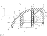
- the upper wall 12 also has a free edge 16, and extends between its free edge 16 and the common edge 18 by presenting a curve, as particularly visible in the figure 4 . It is understood here that the upper wall 12 has a curved profile between the common edge 18 and its free edge 16 seen in the plane perpendicular to the longitudinal direction L, inscribed in a circle.
- the adapter 1 has a triangular section seen in a plane perpendicular to the longitudinal direction L, the triangle of this section being defined by the free edge 14 of the side wall 10, the free edge 16 of the upper wall 12 and by the common edge 18 between the side wall 10 and the upper wall 12. It is thus possible to define an internal volume of the adapter 1, this internal volume being at least partly delimited by the side wall 10 and the upper wall 12.
- the internal volume extends mainly in the form of a right prism with a triangular base.
- the adapter 1 comprises a first internal wall 20 extending at least partly in the internal volume of the adapter 1. More precisely, the first internal wall 20 extends in a plane substantially parallel to the longitudinal L and vertical V directions, from the upper wall 12 in the internal volume. It is understood that the first internal wall 20 extends substantially parallel to the side wall 10.
- the first internal wall 20 participates in delimiting at least in part a reception zone 26 intended to receive the connector 8.
- the connector 8, when the adapter 1 is mounted on the connector 8, is housed at least in part in the reception zone 26.
- the adapter 1 comprises several walls participating in delimiting the reception zone 26, including in particular the first internal wall 20. More particularly, these walls extend in the form of a rectangle, the walls extending in a plane substantially perpendicular to the planes in which the neighboring walls extend. It is therefore understood that the adapter 1 comprises a second internal wall 66 extending parallel to the first internal wall 20, and two side walls 70 extending perpendicular to the longitudinal 66 and internal 20 walls and between the latter.
- the receiving zone 26 is delimited transversely between the first and second internal walls 20, 66, longitudinally between the side walls 70 and vertically by the upper wall 12 and by a mouth 67 defined by the free edges of the internal walls 20, 66 and side walls 70.
- the connector 8 once mounted on the adapter 1, is arranged at least partly in the receiving zone 26 of the adapter 1. In other words, the connector 8 is arranged at least partly between the first internal wall 20 and the second internal wall 66, and between the side walls 70.
- the adapter 1 is rotatably mounted on the connector 8 by means of a rotation device 58.
- the latter comprises several elements cooperating with each other and arranged on the one hand on the connector 8 and on the other hand on the adapter 1.
- the adapter 1 comprises on the one hand a male element 73 on the second internal wall 66 configured to cooperate with a female element of the connector 8, and on the other hand a female element 75 intended to cooperate with a male element of the connector 8.
- the male elements take the form of a tab carrying a strand
- the female elements take the form of an orifice in which the strand is intended to be driven in rotation about the axis of rotation R.
- the tab of the adapter 1 extends, for example, in a plane coincident with the plane in which the second internal wall 66 extends, and is delimited from said second internal wall 66 by two grooves extending along the vertical direction V.
- the tab is elastically deformable while being movable about a direction of rotation parallel to the longitudinal direction L so as to allow the adapter 1 to be mounted on the connector 8.
- the adapter 1 comprises at least one reinforcement 52 extending between the first internal wall 20 and the side wall 10 and/or the upper wall 12.
- the adapter 1 comprises a first series of reinforcements 52a which extend between the upper wall 12, the side wall 10 and the first internal wall 20, and a second series of reinforcements 52b which extend between the upper wall 12 and the second internal wall 66 participating in defining the reception zone 26, said reception zone 26 extending between the first series of reinforcements 52a and the second series of reinforcements 52b.
- the reinforcements 52 of the first series of reinforcements 52a are arranged between the receiving zone 26, the upper wall 12 and the side wall 10, aligning one after the other along a direction parallel to the longitudinal direction L. Furthermore, the reinforcements 52 of the first series of reinforcements 52a advantageously each extend in a plane parallel to the planes in which the reinforcements 52 of said first series of reinforcements 52a extend.
- the reinforcements 52 of the second series of reinforcements 52b are arranged between the receiving zone 26 and the upper wall 12, aligning one after the other along a direction parallel to the longitudinal direction L. Furthermore, the reinforcements 52 of the second series of reinforcements 52b advantageously each extend in a plane parallel to the planes in which the reinforcements 52 of said second series of reinforcements 52b extend.
- the reinforcements 52 of the first series of reinforcements 52a and of the second series of reinforcements 52b each advantageously extend in a plane parallel to the planes in which the reinforcements 52 of said first series of reinforcements 52a and of said second series of reinforcements 52b extend.
- the adapter 1 comprises a receiving housing 32 intended to receive the rod 60 of the arm 4.
- the receiving housing 32 is here defined by a first portion by a sleeve 64, by a second portion open on the internal volume and by a third portion by an opening 54 formed in a reinforcement 52 of the first series of reinforcements 52a.
- the adapter 1 is mounted on the arm 4 so that a free end of the rod 60 first passes through the first portion, then the second portion and finally the third portion.
- the opening 54 is intended to receive at least a part of the rod 60 of the arm 4 and in particular a free end of the rod 60 of the arm 4.
- the sleeve 64 comprises a wall participating in delimiting at least in part the first portion of the receiving housing 32, said wall extending longitudinally taking the form of a hollow cylinder.
- the opening 54 provided in the reinforcement 52 generally takes a shape similar to a section of the sleeve 64 seen in a plane perpendicular to the longitudinal direction. Furthermore, the opening 54 provided in the reinforcement 52 and the sleeve 64 are aligned along a direction parallel to the longitudinal direction L.
- the opening 54 of the reinforcement 52 and the sleeve 64 align along a direction parallel to the longitudinal direction L, the rod 60 of the arm 4 then extending along the longitudinal direction L through the sleeve 64 and the opening 54 of the reinforcement 52.
- the receiving housing 32 generally takes a rectangular shape seen in a section inscribed in a plane perpendicular to the longitudinal direction L, having two large sides 33 of larger dimensions than two other small sides 31, a straight line D of the receiving housing 32 extending along one of the two large sides 33 of the rectangular shape of the receiving housing 32 intersecting the receiving zone 26.
- the adapter 1 comprises a locking device 22 intended to longitudinally secure the adapter 1 relative to the arm 4 of the wiping system 6, the locking device 22 comprising at least one thrust member 28 and a blocking member 30, the thrust member 28 being inscribed in a profile of the upper wall 12 while the blocking member 30 extends at least partly in the receiving housing 32 intended to receive the arm 4.
- the thrust member 28 extends in a profile of the upper wall 12, while the thrust member 28 is movable from the receiving housing 32 towards the first internal wall 20 of the adapter 1.
- the device locking means 22 is pivoted about the pivot direction until the limiting means 24 abuts against the first internal wall 20. This pivoting is sufficient to unlock the position of the adapter 1 by the arm 4 while limiting the risk of breakage of the locking device 22.
Landscapes
- Engineering & Computer Science (AREA)
- Mechanical Engineering (AREA)
- Physics & Mathematics (AREA)
- Fluid Mechanics (AREA)
- Quality & Reliability (AREA)
- Connector Housings Or Holding Contact Members (AREA)
- Cleaning Implements For Floors, Carpets, Furniture, Walls, And The Like (AREA)
- Bidet-Like Cleaning Device And Other Flush Toilet Accessories (AREA)
- Body Washing Hand Wipes And Brushes (AREA)
- Pivots And Pivotal Connections (AREA)
Claims (11)
- Adapter (1) zur Befestigung eines Wischblattes (2) an einem Arm (4) eines Wischsystems (6), wobei sich der Adapter (1) entlang einer Längsrichtung (L) erstreckt, wobei der Adapter (1) dafür ausgelegt ist, an einem Verbinder (8) eines Wischblattes (2) drehbar um eine Drehachse (R), die quer zur Längsrichtung (L) verläuft, angebracht zu werden, wobei der Adapter (1) mindestens eine Seitenwand (10) und eine obere Wand (12) umfasst, die mindestens eine gemeinsamen Rand (18) zwischen sich aufweisen, wobei die Seitenwand (10) und die obere Wand (12) an der Definition eines Innenvolumens des Adapters (1) beteiligt sind, wobei der Adapter (1) eine erste Innenwand (20) und eine zweite Innenwand (66) umfasst, die sich wenigstens teilweise in dem Innenvolumen des Adapters (1) erstrecken und an der wenigstens teilweisen Begrenzung eines Aufnahmebereichs (26) beteiligt sind, der dazu bestimmt ist, den Verbinder (8) aufzunehmen, wobei der Adapter (1) mindestens einen Aufnahmesitz (32) umfasst, der dazu bestimmt ist, den Arm (4) des Wischsystems (6) aufzunehmen, und einen rechteckigen Querschnitt aufweist, der durch zwei große Seiten (33) und zwei kleine Seiten (31) definiert wird, wobei eine Gerade (D), die durch eine der großen Seiten (33) verläuft, den Aufnahmebereich (26) schneidet, der dazu bestimmt ist, den Verbinder (8) aufzunehmen, wobei der Adapter dadurch gekennzeichnet ist, dass er mindestens eine Verstärkung (52) umfasst, die sich zwischen der ersten Innenwand (20) und der Seitenwand (10) und/oder der oberen Wand (12) erstreckt, wobei der Aufnahmesitz (32) durch einen ersten Abschnitt, der eine Hülse (64) umfasst, durch einen zweiten Abschnitt, der am Innenvolumen offen ist, und durch einen dritten Abschnitt, der eine in der Verstärkung (52) ausgebildete Öffnung (54) umfasst, definiert ist.
- Adapter (1) nach dem vorhergehenden Anspruch, wobei die Seitenwand (10) und die obere Wand (12) jeweils einen freien Rand (14, 16) und den Rand (18), welcher der Seitenwand (10) und der oberen Wand (12) gemeinsam ist, aufweisen, wobei der Adapter (1), in einer zur Längsrichtung (L) senkrechten Schnittebene gesehen, einen dreieckigen Querschnitt aufweist, der durch den freien Rand (14) der Seitenwand (10), den freien Rand (16) der oberen Wand (12) und durch den gemeinsamen Rand (18) zwischen der Seitenwand (10) und der oberen Wand (12) definiert ist, wobei die obere Wand (12), in der zur Längsrichtung (L) senkrechten Schnittebene gesehen, zwischen dem gemeinsamen Rand (18) und ihrem freien Rand (16) gekrümmt ist.
- Adapter (1) nach einem der vorhergehenden Ansprüche, welcher eine erste Reihe von Verstärkungen (52a) umfasst, die sich zwischen der oberen Wand (12), der Seitenwand (10) und der ersten Innenwand (20) erstrecken, und eine zweite Reihe von Verstärkungen (52b), die sich zwischen der oberen Wand (12) und einer zweiten Innenwand (66), die an der Definition des Aufnahmebereichs (26) beteiligt ist, erstrecken, wobei sich der Aufnahmebereich (26) zwischen der ersten Reihe von Verstärkungen (52a) und der zweiten Reihe von Verstärkungen (52b) erstreckt.
- Adapter (1) nach einem der vorhergehenden Ansprüche, wobei der Aufnahmesitz (32) bezüglich des Aufnahmebereichs (26) seitlich versetzt ist.
- Adapter (1) nach einem der vorhergehenden Ansprüche, wobei der Aufnahmesitz (32) in dem Innenvolumen zwischen dem Aufnahmebereich (26) und der Seitenwand (10) angeordnet ist.
- Adapter (1) nach einem der vorhergehenden Ansprüche, wobei die Gerade (D), die durch eine der großen Seiten (33) verläuft, die Drehachse (R) des Adapters (1) im Inneren des Aufnahmebereichs (26) schneidet.
- Adapter (1) nach einem der vorhergehenden Ansprüche, welcher eine Verriegelungsvorrichtung (22) umfasst, die dazu bestimmt ist, den Adapter (1) bezüglich des Armes (4) des Wischsystems (6) in Längsrichtung fest zu verbinden, wobei die Verriegelungsvorrichtung (22) mindestens ein Schuborgan (28) und ein Blockierorgan (30) umfasst, wobei das Schuborgan (28) in einem Profil der oberen Wand (12) liegt, während das Blockierorgan (30) sich wenigstens teilweise in dem Aufnahmesitz (32) erstreckt, der dazu bestimmt ist, den Arm (4) aufzunehmen.
- Verbindungsvorrichtung (56) für ein Wischblatt (2), welche mindestens einen Verbinder (8) und einen Adapter (1) nach einem der vorhergehenden Ansprüche umfasst, wobei der Verbinder (8) mittels einer Drehvorrichtung (58) um die Drehachse (R) des Adapters (1) drehbar angebracht ist.
- Wischblatt (2), welches mindestens eine Verbindungsvorrichtung (56) nach dem vorhergehenden Anspruch oder einen Adapter (1) nach einem der Ansprüche 1 bis 7 umfasst.
- Wischsystem (6), welches mindestens einen Arm (4) und ein Wischblatt (2) nach dem vorhergehenden Anspruch umfasst, wobei der Arm (4) mindestens eine Stange (60) umfasst, die in dem Aufnahmesitz (32) des Adapters (1) aufgenommen ist.
- Wischsystem (6) nach dem vorhergehenden Anspruch, wobei mindestens ein Ende der Stange (60) eine zu dem Aufnahmesitz (32) des Adapters (1) komplementäre Form aufweist, wobei die Stange (60) einen Einschnitt (62) aufweist, der mit einer Verriegelungsvorrichtung (22) zusammenwirkt, um die Position des Adapters (1) auf der Stange (60) in Längsrichtung zu blockieren.
Applications Claiming Priority (1)
| Application Number | Priority Date | Filing Date | Title |
|---|---|---|---|
| FR2109139A FR3126380B1 (fr) | 2021-09-01 | 2021-09-01 | Adaptateur d’un système d’essuyage. |
Publications (2)
| Publication Number | Publication Date |
|---|---|
| EP4144600A1 EP4144600A1 (de) | 2023-03-08 |
| EP4144600B1 true EP4144600B1 (de) | 2024-11-20 |
Family
ID=77913317
Family Applications (1)
| Application Number | Title | Priority Date | Filing Date |
|---|---|---|---|
| EP22191790.9A Active EP4144600B1 (de) | 2021-09-01 | 2022-08-23 | Adapter für reinigungssystem |
Country Status (4)
| Country | Link |
|---|---|
| US (1) | US12012077B2 (de) |
| EP (1) | EP4144600B1 (de) |
| CN (2) | CN115723710B (de) |
| FR (1) | FR3126380B1 (de) |
Families Citing this family (2)
| Publication number | Priority date | Publication date | Assignee | Title |
|---|---|---|---|---|
| FR3148194A1 (fr) * | 2023-04-28 | 2024-11-01 | Valeo Systemes D'essuyage | Adaptateur pour balai d’essuie-glace et dispositif d’essuyage |
| FR3152138A1 (fr) * | 2024-01-19 | 2025-02-21 | Valeo Systemes D Essuyage | Adaptateur pour balai d’essuie-glace et dispositif d’essuyage |
Family Cites Families (10)
| Publication number | Priority date | Publication date | Assignee | Title |
|---|---|---|---|---|
| DE50309219D1 (de) * | 2002-11-26 | 2008-04-03 | Valeo Wischersysteme Gmbh | Vorrichtung zum lösbaren verbinden eines wischblatts mit einem antreibbaren wischarm |
| DE102011089545A1 (de) * | 2011-12-22 | 2013-06-27 | Robert Bosch Gmbh | Anschlusselement zum gelenkigen Verbinden eines Wischarms mit einem Wischblatt |
| US9626212B2 (en) * | 2014-06-28 | 2017-04-18 | Vmware, Inc. | Live migration of virtual machines with memory state sharing |
| WO2016119852A1 (en) * | 2015-01-29 | 2016-08-04 | Federal-Mogul S.A. | A windscreen wiper device of the flat blade type |
| EP3383711B1 (de) * | 2015-12-02 | 2020-06-03 | Valeo Systèmes d'Essuyage | Adapter für einen antriebsarm eines wischsystems |
| DE102016211162A1 (de) * | 2016-06-22 | 2017-12-28 | Robert Bosch Gmbh | Wischblattadaptervorrichtung |
| DE202018006138U1 (de) * | 2018-07-30 | 2019-04-25 | Robert Bosch Gmbh | Adaptereinheit |
| CN112469601B (zh) * | 2018-07-30 | 2025-02-25 | 罗伯特·博世有限公司 | 刮水臂适配器单元和适配器单元 |
| DE202018006136U1 (de) * | 2018-09-26 | 2019-04-25 | Robert Bosch Gmbh | Wischarm und Wischvorrichtung |
| DE202018006137U1 (de) * | 2018-09-26 | 2019-04-25 | Robert Bosch Gmbh | Adaptereinheit und Wischvorrichtung |
-
2021
- 2021-09-01 FR FR2109139A patent/FR3126380B1/fr active Active
-
2022
- 2022-08-23 EP EP22191790.9A patent/EP4144600B1/de active Active
- 2022-08-31 CN CN202211062245.8A patent/CN115723710B/zh active Active
- 2022-08-31 CN CN202511268564.8A patent/CN120902676A/zh active Pending
- 2022-09-01 US US17/901,118 patent/US12012077B2/en active Active
Also Published As
| Publication number | Publication date |
|---|---|
| US20230166692A1 (en) | 2023-06-01 |
| FR3126380A1 (fr) | 2023-03-03 |
| CN120902676A (zh) | 2025-11-07 |
| CN115723710B (zh) | 2025-08-19 |
| US12012077B2 (en) | 2024-06-18 |
| FR3126380B1 (fr) | 2024-05-17 |
| EP4144600A1 (de) | 2023-03-08 |
| CN115723710A (zh) | 2023-03-03 |
Similar Documents
| Publication | Publication Date | Title |
|---|---|---|
| EP4144600A1 (de) | Adapter für reinigungssystem | |
| EP2900526A1 (de) | Fensterwischsystem, insbesondere für die heckscheibe eines motorfahrzeuges | |
| EP4144599B1 (de) | Adapter für reinigungssystem | |
| FR2744973A1 (fr) | Essuie-glace de vehicule automobile muni d'un capot d'habillage porte par un connecteur d'articulation du balai sur le bras d'essuie-glace | |
| FR3031712A1 (fr) | Capot d’essuie-glace configure pour recouvrir une partie terminale d’un bras d’essuie-glace | |
| EP0791514A2 (de) | Scheibenwischer für Kraftfahrzeuge mit Verkleidung für Endstück | |
| WO2022219097A1 (fr) | Capot pour ensemble d'essuyage pour véhicule automobile | |
| WO2024126418A1 (fr) | Adaptateur d'un système d'essuyage | |
| WO2023030973A1 (fr) | Adaptateur d'un système d'essuyage | |
| FR2752798A1 (fr) | Essuie-glace comportant un adaptateur d'articulation | |
| EP3902721A1 (de) | Adapter für ein wischerblatt eines kraftfahrzeugs | |
| EP4188759A1 (de) | Anschlussvorrichtung für eine fahrzeugscheibenwischeranlage | |
| EP4188757B1 (de) | Verbinder für ein wischblatt | |
| WO2023208726A1 (fr) | Ensemble de connexion d'un système d'essuyage | |
| WO2020135959A1 (fr) | Adaptateur pour balai d'essuie-glace de véhicule automobile | |
| FR3100772A1 (fr) | aménagement de parechoc pour véhicule automobile | |
| FR2868377A1 (fr) | Balai d'essuie-glace | |
| WO2024126417A1 (fr) | Adaptateur d'un système d'essuyage | |
| WO2018050326A1 (fr) | Adaptateur pour la connexion d'un balai d'essuyage a un bras d'entrainement d'un systeme d'essuyage pour vehicule automobile | |
| WO2022175417A1 (fr) | Système de connexion d'un balai d'essuyage sur un bras d'un système d'essuyage | |
| WO2023222840A1 (fr) | Dispositif de connexion d'un balai d'essuyage | |
| WO2025146493A1 (fr) | Adaptateur pour l'assemblage d'un balai à un bras d'essuie-glace | |
| WO2023222838A1 (fr) | Module de connexion d'un système d'essuyage. | |
| WO2023222802A1 (fr) | Dispositif de connexion d'un balai d'essuyage | |
| FR3091231A1 (fr) | Connecteur constitutif d’un balai d’essuyage et balai d’essuyage comprenant un tel connecteur |
Legal Events
| Date | Code | Title | Description |
|---|---|---|---|
| PUAI | Public reference made under article 153(3) epc to a published international application that has entered the european phase |
Free format text: ORIGINAL CODE: 0009012 |
|
| STAA | Information on the status of an ep patent application or granted ep patent |
Free format text: STATUS: THE APPLICATION HAS BEEN PUBLISHED |
|
| AK | Designated contracting states |
Kind code of ref document: A1 Designated state(s): AL AT BE BG CH CY CZ DE DK EE ES FI FR GB GR HR HU IE IS IT LI LT LU LV MC MK MT NL NO PL PT RO RS SE SI SK SM TR |
|
| STAA | Information on the status of an ep patent application or granted ep patent |
Free format text: STATUS: REQUEST FOR EXAMINATION WAS MADE |
|
| 17P | Request for examination filed |
Effective date: 20230818 |
|
| RBV | Designated contracting states (corrected) |
Designated state(s): AL AT BE BG CH CY CZ DE DK EE ES FI FR GB GR HR HU IE IS IT LI LT LU LV MC MK MT NL NO PL PT RO RS SE SI SK SM TR |
|
| GRAP | Despatch of communication of intention to grant a patent |
Free format text: ORIGINAL CODE: EPIDOSNIGR1 |
|
| STAA | Information on the status of an ep patent application or granted ep patent |
Free format text: STATUS: GRANT OF PATENT IS INTENDED |
|
| INTG | Intention to grant announced |
Effective date: 20240613 |
|
| GRAS | Grant fee paid |
Free format text: ORIGINAL CODE: EPIDOSNIGR3 |
|
| GRAA | (expected) grant |
Free format text: ORIGINAL CODE: 0009210 |
|
| STAA | Information on the status of an ep patent application or granted ep patent |
Free format text: STATUS: THE PATENT HAS BEEN GRANTED |
|
| AK | Designated contracting states |
Kind code of ref document: B1 Designated state(s): AL AT BE BG CH CY CZ DE DK EE ES FI FR GB GR HR HU IE IS IT LI LT LU LV MC MK MT NL NO PL PT RO RS SE SI SK SM TR |
|
| REG | Reference to a national code |
Ref country code: GB Ref legal event code: FG4D Free format text: NOT ENGLISH |
|
| REG | Reference to a national code |
Ref country code: CH Ref legal event code: EP |
|
| REG | Reference to a national code |
Ref country code: DE Ref legal event code: R096 Ref document number: 602022007865 Country of ref document: DE |
|
| REG | Reference to a national code |
Ref country code: IE Ref legal event code: FG4D Free format text: LANGUAGE OF EP DOCUMENT: FRENCH |
|
| REG | Reference to a national code |
Ref country code: LT Ref legal event code: MG9D |
|
| REG | Reference to a national code |
Ref country code: NL Ref legal event code: MP Effective date: 20241120 |
|
| PG25 | Lapsed in a contracting state [announced via postgrant information from national office to epo] |
Ref country code: PT Free format text: LAPSE BECAUSE OF FAILURE TO SUBMIT A TRANSLATION OF THE DESCRIPTION OR TO PAY THE FEE WITHIN THE PRESCRIBED TIME-LIMIT Effective date: 20250320 Ref country code: HR Free format text: LAPSE BECAUSE OF FAILURE TO SUBMIT A TRANSLATION OF THE DESCRIPTION OR TO PAY THE FEE WITHIN THE PRESCRIBED TIME-LIMIT Effective date: 20241120 Ref country code: IS Free format text: LAPSE BECAUSE OF FAILURE TO SUBMIT A TRANSLATION OF THE DESCRIPTION OR TO PAY THE FEE WITHIN THE PRESCRIBED TIME-LIMIT Effective date: 20250320 |
|
| PG25 | Lapsed in a contracting state [announced via postgrant information from national office to epo] |
Ref country code: FI Free format text: LAPSE BECAUSE OF FAILURE TO SUBMIT A TRANSLATION OF THE DESCRIPTION OR TO PAY THE FEE WITHIN THE PRESCRIBED TIME-LIMIT Effective date: 20241120 Ref country code: NL Free format text: LAPSE BECAUSE OF FAILURE TO SUBMIT A TRANSLATION OF THE DESCRIPTION OR TO PAY THE FEE WITHIN THE PRESCRIBED TIME-LIMIT Effective date: 20241120 |
|
| REG | Reference to a national code |
Ref country code: AT Ref legal event code: MK05 Ref document number: 1743318 Country of ref document: AT Kind code of ref document: T Effective date: 20241120 |
|
| PG25 | Lapsed in a contracting state [announced via postgrant information from national office to epo] |
Ref country code: BG Free format text: LAPSE BECAUSE OF FAILURE TO SUBMIT A TRANSLATION OF THE DESCRIPTION OR TO PAY THE FEE WITHIN THE PRESCRIBED TIME-LIMIT Effective date: 20241120 |
|
| PG25 | Lapsed in a contracting state [announced via postgrant information from national office to epo] |
Ref country code: ES Free format text: LAPSE BECAUSE OF FAILURE TO SUBMIT A TRANSLATION OF THE DESCRIPTION OR TO PAY THE FEE WITHIN THE PRESCRIBED TIME-LIMIT Effective date: 20241120 |
|
| PG25 | Lapsed in a contracting state [announced via postgrant information from national office to epo] |
Ref country code: NO Free format text: LAPSE BECAUSE OF FAILURE TO SUBMIT A TRANSLATION OF THE DESCRIPTION OR TO PAY THE FEE WITHIN THE PRESCRIBED TIME-LIMIT Effective date: 20250220 |
|
| PG25 | Lapsed in a contracting state [announced via postgrant information from national office to epo] |
Ref country code: AT Free format text: LAPSE BECAUSE OF FAILURE TO SUBMIT A TRANSLATION OF THE DESCRIPTION OR TO PAY THE FEE WITHIN THE PRESCRIBED TIME-LIMIT Effective date: 20241120 Ref country code: LV Free format text: LAPSE BECAUSE OF FAILURE TO SUBMIT A TRANSLATION OF THE DESCRIPTION OR TO PAY THE FEE WITHIN THE PRESCRIBED TIME-LIMIT Effective date: 20241120 Ref country code: GR Free format text: LAPSE BECAUSE OF FAILURE TO SUBMIT A TRANSLATION OF THE DESCRIPTION OR TO PAY THE FEE WITHIN THE PRESCRIBED TIME-LIMIT Effective date: 20250221 |
|
| PG25 | Lapsed in a contracting state [announced via postgrant information from national office to epo] |
Ref country code: PL Free format text: LAPSE BECAUSE OF FAILURE TO SUBMIT A TRANSLATION OF THE DESCRIPTION OR TO PAY THE FEE WITHIN THE PRESCRIBED TIME-LIMIT Effective date: 20241120 |
|
| PG25 | Lapsed in a contracting state [announced via postgrant information from national office to epo] |
Ref country code: RS Free format text: LAPSE BECAUSE OF FAILURE TO SUBMIT A TRANSLATION OF THE DESCRIPTION OR TO PAY THE FEE WITHIN THE PRESCRIBED TIME-LIMIT Effective date: 20250220 |
|
| PG25 | Lapsed in a contracting state [announced via postgrant information from national office to epo] |
Ref country code: SM Free format text: LAPSE BECAUSE OF FAILURE TO SUBMIT A TRANSLATION OF THE DESCRIPTION OR TO PAY THE FEE WITHIN THE PRESCRIBED TIME-LIMIT Effective date: 20241120 |
|
| PG25 | Lapsed in a contracting state [announced via postgrant information from national office to epo] |
Ref country code: DK Free format text: LAPSE BECAUSE OF FAILURE TO SUBMIT A TRANSLATION OF THE DESCRIPTION OR TO PAY THE FEE WITHIN THE PRESCRIBED TIME-LIMIT Effective date: 20241120 |
|
| PG25 | Lapsed in a contracting state [announced via postgrant information from national office to epo] |
Ref country code: EE Free format text: LAPSE BECAUSE OF FAILURE TO SUBMIT A TRANSLATION OF THE DESCRIPTION OR TO PAY THE FEE WITHIN THE PRESCRIBED TIME-LIMIT Effective date: 20241120 |
|
| PG25 | Lapsed in a contracting state [announced via postgrant information from national office to epo] |
Ref country code: RO Free format text: LAPSE BECAUSE OF FAILURE TO SUBMIT A TRANSLATION OF THE DESCRIPTION OR TO PAY THE FEE WITHIN THE PRESCRIBED TIME-LIMIT Effective date: 20241120 |
|
| PG25 | Lapsed in a contracting state [announced via postgrant information from national office to epo] |
Ref country code: SK Free format text: LAPSE BECAUSE OF FAILURE TO SUBMIT A TRANSLATION OF THE DESCRIPTION OR TO PAY THE FEE WITHIN THE PRESCRIBED TIME-LIMIT Effective date: 20241120 |
|
| PG25 | Lapsed in a contracting state [announced via postgrant information from national office to epo] |
Ref country code: CZ Free format text: LAPSE BECAUSE OF FAILURE TO SUBMIT A TRANSLATION OF THE DESCRIPTION OR TO PAY THE FEE WITHIN THE PRESCRIBED TIME-LIMIT Effective date: 20241120 |
|
| PG25 | Lapsed in a contracting state [announced via postgrant information from national office to epo] |
Ref country code: IT Free format text: LAPSE BECAUSE OF FAILURE TO SUBMIT A TRANSLATION OF THE DESCRIPTION OR TO PAY THE FEE WITHIN THE PRESCRIBED TIME-LIMIT Effective date: 20241120 |
|
| REG | Reference to a national code |
Ref country code: DE Ref legal event code: R097 Ref document number: 602022007865 Country of ref document: DE |
|
| PG25 | Lapsed in a contracting state [announced via postgrant information from national office to epo] |
Ref country code: SE Free format text: LAPSE BECAUSE OF FAILURE TO SUBMIT A TRANSLATION OF THE DESCRIPTION OR TO PAY THE FEE WITHIN THE PRESCRIBED TIME-LIMIT Effective date: 20241120 |
|
| PLBE | No opposition filed within time limit |
Free format text: ORIGINAL CODE: 0009261 |
|
| STAA | Information on the status of an ep patent application or granted ep patent |
Free format text: STATUS: NO OPPOSITION FILED WITHIN TIME LIMIT |
|
| PGFP | Annual fee paid to national office [announced via postgrant information from national office to epo] |
Ref country code: DE Payment date: 20250812 Year of fee payment: 4 |
|
| PGFP | Annual fee paid to national office [announced via postgrant information from national office to epo] |
Ref country code: FR Payment date: 20250828 Year of fee payment: 4 |
|
| 26N | No opposition filed |
Effective date: 20250821 |
|
| REG | Reference to a national code |
Ref country code: CH Ref legal event code: H13 Free format text: ST27 STATUS EVENT CODE: U-0-0-H10-H13 (AS PROVIDED BY THE NATIONAL OFFICE) Effective date: 20260324 |
|
| PG25 | Lapsed in a contracting state [announced via postgrant information from national office to epo] |
Ref country code: MC Free format text: LAPSE BECAUSE OF FAILURE TO SUBMIT A TRANSLATION OF THE DESCRIPTION OR TO PAY THE FEE WITHIN THE PRESCRIBED TIME-LIMIT Effective date: 20241120 |
|
| PG25 | Lapsed in a contracting state [announced via postgrant information from national office to epo] |
Ref country code: LU Free format text: LAPSE BECAUSE OF NON-PAYMENT OF DUE FEES Effective date: 20250823 |
|
| PG25 | Lapsed in a contracting state [announced via postgrant information from national office to epo] |
Ref country code: CH Free format text: LAPSE BECAUSE OF NON-PAYMENT OF DUE FEES Effective date: 20250831 |