EP4144603A1 - Rückschlagventil und bremssystem - Google Patents
Rückschlagventil und bremssystem Download PDFInfo
- Publication number
- EP4144603A1 EP4144603A1 EP21796734.8A EP21796734A EP4144603A1 EP 4144603 A1 EP4144603 A1 EP 4144603A1 EP 21796734 A EP21796734 A EP 21796734A EP 4144603 A1 EP4144603 A1 EP 4144603A1
- Authority
- EP
- European Patent Office
- Prior art keywords
- check valve
- extension
- plug
- cap
- retainer
- Prior art date
- Legal status (The legal status is an assumption and is not a legal conclusion. Google has not performed a legal analysis and makes no representation as to the accuracy of the status listed.)
- Pending
Links
Images


Classifications
-
- B—PERFORMING OPERATIONS; TRANSPORTING
- B60—VEHICLES IN GENERAL
- B60T—VEHICLE BRAKE CONTROL SYSTEMS OR PARTS THEREOF; BRAKE CONTROL SYSTEMS OR PARTS THEREOF, IN GENERAL; ARRANGEMENT OF BRAKING ELEMENTS ON VEHICLES IN GENERAL; PORTABLE DEVICES FOR PREVENTING UNWANTED MOVEMENT OF VEHICLES; VEHICLE MODIFICATIONS TO FACILITATE COOLING OF BRAKES
- B60T15/00—Construction arrangement, or operation of valves incorporated in power brake systems and not covered by groups B60T11/00 or B60T13/00
- B60T15/02—Application and release valves
- B60T15/36—Other control devices or valves characterised by definite functions
-
- F—MECHANICAL ENGINEERING; LIGHTING; HEATING; WEAPONS; BLASTING
- F16—ENGINEERING ELEMENTS AND UNITS; GENERAL MEASURES FOR PRODUCING AND MAINTAINING EFFECTIVE FUNCTIONING OF MACHINES OR INSTALLATIONS; THERMAL INSULATION IN GENERAL
- F16J—PISTONS; CYLINDERS; SEALINGS
- F16J15/00—Sealings
- F16J15/16—Sealings between relatively-moving surfaces
- F16J15/32—Sealings between relatively-moving surfaces with elastic sealings, e.g. O-rings
- F16J15/3204—Sealings between relatively-moving surfaces with elastic sealings, e.g. O-rings with at least one lip
-
- B—PERFORMING OPERATIONS; TRANSPORTING
- B60—VEHICLES IN GENERAL
- B60T—VEHICLE BRAKE CONTROL SYSTEMS OR PARTS THEREOF; BRAKE CONTROL SYSTEMS OR PARTS THEREOF, IN GENERAL; ARRANGEMENT OF BRAKING ELEMENTS ON VEHICLES IN GENERAL; PORTABLE DEVICES FOR PREVENTING UNWANTED MOVEMENT OF VEHICLES; VEHICLE MODIFICATIONS TO FACILITATE COOLING OF BRAKES
- B60T13/00—Transmitting braking action from initiating means to ultimate brake actuator with power assistance or drive; Brake systems incorporating such transmitting means, e.g. air-pressure brake systems
- B60T13/10—Transmitting braking action from initiating means to ultimate brake actuator with power assistance or drive; Brake systems incorporating such transmitting means, e.g. air-pressure brake systems with fluid assistance, drive, or release
- B60T13/12—Transmitting braking action from initiating means to ultimate brake actuator with power assistance or drive; Brake systems incorporating such transmitting means, e.g. air-pressure brake systems with fluid assistance, drive, or release the fluid being liquid
- B60T13/14—Transmitting braking action from initiating means to ultimate brake actuator with power assistance or drive; Brake systems incorporating such transmitting means, e.g. air-pressure brake systems with fluid assistance, drive, or release the fluid being liquid using accumulators or reservoirs fed by pumps
- B60T13/142—Systems with master cylinder
- B60T13/145—Master cylinder integrated or hydraulically coupled with booster
- B60T13/146—Part of the system directly actuated by booster pressure
-
- B—PERFORMING OPERATIONS; TRANSPORTING
- B60—VEHICLES IN GENERAL
- B60T—VEHICLE BRAKE CONTROL SYSTEMS OR PARTS THEREOF; BRAKE CONTROL SYSTEMS OR PARTS THEREOF, IN GENERAL; ARRANGEMENT OF BRAKING ELEMENTS ON VEHICLES IN GENERAL; PORTABLE DEVICES FOR PREVENTING UNWANTED MOVEMENT OF VEHICLES; VEHICLE MODIFICATIONS TO FACILITATE COOLING OF BRAKES
- B60T13/00—Transmitting braking action from initiating means to ultimate brake actuator with power assistance or drive; Brake systems incorporating such transmitting means, e.g. air-pressure brake systems
- B60T13/10—Transmitting braking action from initiating means to ultimate brake actuator with power assistance or drive; Brake systems incorporating such transmitting means, e.g. air-pressure brake systems with fluid assistance, drive, or release
- B60T13/12—Transmitting braking action from initiating means to ultimate brake actuator with power assistance or drive; Brake systems incorporating such transmitting means, e.g. air-pressure brake systems with fluid assistance, drive, or release the fluid being liquid
- B60T13/14—Transmitting braking action from initiating means to ultimate brake actuator with power assistance or drive; Brake systems incorporating such transmitting means, e.g. air-pressure brake systems with fluid assistance, drive, or release the fluid being liquid using accumulators or reservoirs fed by pumps
- B60T13/148—Arrangements for pressure supply
-
- B—PERFORMING OPERATIONS; TRANSPORTING
- B60—VEHICLES IN GENERAL
- B60T—VEHICLE BRAKE CONTROL SYSTEMS OR PARTS THEREOF; BRAKE CONTROL SYSTEMS OR PARTS THEREOF, IN GENERAL; ARRANGEMENT OF BRAKING ELEMENTS ON VEHICLES IN GENERAL; PORTABLE DEVICES FOR PREVENTING UNWANTED MOVEMENT OF VEHICLES; VEHICLE MODIFICATIONS TO FACILITATE COOLING OF BRAKES
- B60T13/00—Transmitting braking action from initiating means to ultimate brake actuator with power assistance or drive; Brake systems incorporating such transmitting means, e.g. air-pressure brake systems
- B60T13/10—Transmitting braking action from initiating means to ultimate brake actuator with power assistance or drive; Brake systems incorporating such transmitting means, e.g. air-pressure brake systems with fluid assistance, drive, or release
- B60T13/66—Electrical control in fluid-pressure brake systems
- B60T13/662—Electrical control in fluid-pressure brake systems characterised by specified functions of the control system components
-
- B—PERFORMING OPERATIONS; TRANSPORTING
- B60—VEHICLES IN GENERAL
- B60T—VEHICLE BRAKE CONTROL SYSTEMS OR PARTS THEREOF; BRAKE CONTROL SYSTEMS OR PARTS THEREOF, IN GENERAL; ARRANGEMENT OF BRAKING ELEMENTS ON VEHICLES IN GENERAL; PORTABLE DEVICES FOR PREVENTING UNWANTED MOVEMENT OF VEHICLES; VEHICLE MODIFICATIONS TO FACILITATE COOLING OF BRAKES
- B60T13/00—Transmitting braking action from initiating means to ultimate brake actuator with power assistance or drive; Brake systems incorporating such transmitting means, e.g. air-pressure brake systems
- B60T13/10—Transmitting braking action from initiating means to ultimate brake actuator with power assistance or drive; Brake systems incorporating such transmitting means, e.g. air-pressure brake systems with fluid assistance, drive, or release
- B60T13/66—Electrical control in fluid-pressure brake systems
- B60T13/68—Electrical control in fluid-pressure brake systems by electrically-controlled valves
- B60T13/686—Electrical control in fluid-pressure brake systems by electrically-controlled valves in hydraulic systems or parts thereof
-
- B—PERFORMING OPERATIONS; TRANSPORTING
- B60—VEHICLES IN GENERAL
- B60T—VEHICLE BRAKE CONTROL SYSTEMS OR PARTS THEREOF; BRAKE CONTROL SYSTEMS OR PARTS THEREOF, IN GENERAL; ARRANGEMENT OF BRAKING ELEMENTS ON VEHICLES IN GENERAL; PORTABLE DEVICES FOR PREVENTING UNWANTED MOVEMENT OF VEHICLES; VEHICLE MODIFICATIONS TO FACILITATE COOLING OF BRAKES
- B60T13/00—Transmitting braking action from initiating means to ultimate brake actuator with power assistance or drive; Brake systems incorporating such transmitting means, e.g. air-pressure brake systems
- B60T13/74—Transmitting braking action from initiating means to ultimate brake actuator with power assistance or drive; Brake systems incorporating such transmitting means, e.g. air-pressure brake systems with electrical assistance or drive
- B60T13/745—Transmitting braking action from initiating means to ultimate brake actuator with power assistance or drive; Brake systems incorporating such transmitting means, e.g. air-pressure brake systems with electrical assistance or drive acting on a hydraulic system, e.g. a master cylinder
-
- B—PERFORMING OPERATIONS; TRANSPORTING
- B60—VEHICLES IN GENERAL
- B60T—VEHICLE BRAKE CONTROL SYSTEMS OR PARTS THEREOF; BRAKE CONTROL SYSTEMS OR PARTS THEREOF, IN GENERAL; ARRANGEMENT OF BRAKING ELEMENTS ON VEHICLES IN GENERAL; PORTABLE DEVICES FOR PREVENTING UNWANTED MOVEMENT OF VEHICLES; VEHICLE MODIFICATIONS TO FACILITATE COOLING OF BRAKES
- B60T17/00—Component parts, details, or accessories of power brake systems not covered by groups B60T8/00, B60T13/00 or B60T15/00, or presenting other characteristic features
- B60T17/18—Safety devices; Monitoring
- B60T17/22—Devices for monitoring or checking brake systems; Signal devices
-
- B—PERFORMING OPERATIONS; TRANSPORTING
- B60—VEHICLES IN GENERAL
- B60T—VEHICLE BRAKE CONTROL SYSTEMS OR PARTS THEREOF; BRAKE CONTROL SYSTEMS OR PARTS THEREOF, IN GENERAL; ARRANGEMENT OF BRAKING ELEMENTS ON VEHICLES IN GENERAL; PORTABLE DEVICES FOR PREVENTING UNWANTED MOVEMENT OF VEHICLES; VEHICLE MODIFICATIONS TO FACILITATE COOLING OF BRAKES
- B60T7/00—Brake-action initiating means
- B60T7/02—Brake-action initiating means for personal initiation
- B60T7/04—Brake-action initiating means for personal initiation foot actuated
- B60T7/042—Brake-action initiating means for personal initiation foot actuated by electrical means, e.g. using travel or force sensors
-
- B—PERFORMING OPERATIONS; TRANSPORTING
- B60—VEHICLES IN GENERAL
- B60T—VEHICLE BRAKE CONTROL SYSTEMS OR PARTS THEREOF; BRAKE CONTROL SYSTEMS OR PARTS THEREOF, IN GENERAL; ARRANGEMENT OF BRAKING ELEMENTS ON VEHICLES IN GENERAL; PORTABLE DEVICES FOR PREVENTING UNWANTED MOVEMENT OF VEHICLES; VEHICLE MODIFICATIONS TO FACILITATE COOLING OF BRAKES
- B60T8/00—Arrangements for adjusting wheel-braking force to meet varying vehicular or ground-surface conditions, e.g. limiting or varying distribution of braking force
- B60T8/32—Arrangements for adjusting wheel-braking force to meet varying vehicular or ground-surface conditions, e.g. limiting or varying distribution of braking force responsive to a speed condition, e.g. acceleration or deceleration
- B60T8/34—Arrangements for adjusting wheel-braking force to meet varying vehicular or ground-surface conditions, e.g. limiting or varying distribution of braking force responsive to a speed condition, e.g. acceleration or deceleration having a fluid pressure regulator responsive to a speed condition
- B60T8/40—Arrangements for adjusting wheel-braking force to meet varying vehicular or ground-surface conditions, e.g. limiting or varying distribution of braking force responsive to a speed condition, e.g. acceleration or deceleration having a fluid pressure regulator responsive to a speed condition comprising an additional fluid circuit including fluid pressurising means for modifying the pressure of the braking fluid, e.g. including wheel driven pumps for detecting a speed condition, or pumps which are controlled by means independent of the braking system
- B60T8/4072—Systems in which a driver input signal is used as a control signal for the additional fluid circuit which is normally used for braking
- B60T8/4081—Systems with stroke simulating devices for driver input
-
- F—MECHANICAL ENGINEERING; LIGHTING; HEATING; WEAPONS; BLASTING
- F15—FLUID-PRESSURE ACTUATORS; HYDRAULICS OR PNEUMATICS IN GENERAL
- F15B—SYSTEMS ACTING BY MEANS OF FLUIDS IN GENERAL; FLUID-PRESSURE ACTUATORS, e.g. SERVOMOTORS; DETAILS OF FLUID-PRESSURE SYSTEMS, NOT OTHERWISE PROVIDED FOR
- F15B13/00—Details of servomotor systems ; Valves for servomotor systems
- F15B13/02—Fluid distribution or supply devices characterised by their adaptation to the control of servomotors
- F15B13/027—Check valves
-
- F—MECHANICAL ENGINEERING; LIGHTING; HEATING; WEAPONS; BLASTING
- F16—ENGINEERING ELEMENTS AND UNITS; GENERAL MEASURES FOR PRODUCING AND MAINTAINING EFFECTIVE FUNCTIONING OF MACHINES OR INSTALLATIONS; THERMAL INSULATION IN GENERAL
- F16K—VALVES; TAPS; COCKS; ACTUATING-FLOATS; DEVICES FOR VENTING OR AERATING
- F16K15/00—Check valves
- F16K15/02—Check valves with guided rigid valve members
- F16K15/06—Check valves with guided rigid valve members with guided stems
- F16K15/063—Check valves with guided rigid valve members with guided stems the valve being loaded by a spring
-
- F—MECHANICAL ENGINEERING; LIGHTING; HEATING; WEAPONS; BLASTING
- F16—ENGINEERING ELEMENTS AND UNITS; GENERAL MEASURES FOR PRODUCING AND MAINTAINING EFFECTIVE FUNCTIONING OF MACHINES OR INSTALLATIONS; THERMAL INSULATION IN GENERAL
- F16K—VALVES; TAPS; COCKS; ACTUATING-FLOATS; DEVICES FOR VENTING OR AERATING
- F16K2200/00—Details of valves
- F16K2200/50—Self-contained valve assemblies
- F16K2200/502—Cages for valves, i.e. means to be inserted within the valve housing, surrounding and guiding the closure member
Definitions
- Patent Document 1 discloses a well-known conventional brake system with a check valve.
- the brake system in Patent Document 1 aspirates brake fluid from the reservoir tank into the slave cylinder via the supply path.
- the check valve is provided in the supply path to prevent brake fluid pressure generated in the slave cylinder from being transmitted toward the reservoir tank.
- the present invention is intended to provide a check valve and a brake system to reduce manufacturing costs and suitably prevent grit and dust from entering therein.
- the first extension is formed with a groove
- the retainer is provided with a second protrusion to engage with the groove.
- the second extension and the cylindrical wall are each formed with a flow-through portion to allow hydraulic fluid to flow therethrough. This configuration allows hydraulic fluid to flow through the flow-through portions, to prevent sliding lock due to fluid tightness.
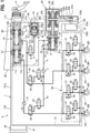
- the master cylinder 10 is a tandem piston type having two first pistons 12a and 12b.
- the first cylinder hole 11 accommodates therein two coil springs 17a and 17b.
- a rod P1 of the brake pedal P is inserted into the first cylinder hole 11 and connected to the first piston 12b. Both the first pistons 12a and 12b receive pedal pressure of the brake pedal P and slide in the first cylinder hole 11, to pressurize brake fluid in the bottom-side pressure chamber 16a and the opening-side pressure chamber 16b.
- a bottom surface 41a of the third cylinder hole 41 and the third piston 42 defines a pressure chamber 45 therebetween.
- the pressure chamber 45 leads to the opening-side pressure chamber 16b of the first cylinder hole 11 via the branch hydraulic path 3 and the second main hydraulic path 2b, which are to be described below.
- brake fluid pressure generated in the opening-side pressure chamber 16b of the master cylinder 10 moves the third piston 42 against a biasing force of the coil springs 43a and 43b. This applies a pseudo operation reaction force to the brake pedal P.
- the rod 25a is inserted into the second cylinder hole 21 through the opening 21b of the second cylinder hole 21, and an end of the rod 25a abuts on the second piston 22.
- a ball screw mechanism is provided between an outer peripheral surface of the rod 25a and an inner peripheral surface of the nut member 25b.
- the two main hydraulic paths 2a and 2b are hydraulic paths starting from the first cylinder hole 11 of the master cylinder 10.
- the first main hydraulic path 2a is connected to the two wheel brakes BR from the bottom-side pressure chamber 16a of the master cylinder 10 via the hydraulic pressure control unit 30.
- the second main hydraulic path 2b is connected to the other two wheel brakes BR from the opening-side pressure chamber 16b of the master cylinder 10 via the hydraulic pressure control unit 30.
- the two communication paths 5a and 5b are hydraulic paths starting from the second cylinder hole 21 of the slave cylinder 20. Both the communication paths 5a and 5b join the common hydraulic path 4 and a discharging fluid path 4a, and lead to the second cylinder hole 21.
- the first communication path 5a is a flow path from the pressure chamber 26 in the second cylinder hole 21 to the first main hydraulic path 2a
- the second continuous path 5b is a flow path from the pressure chamber 26 to the second main hydraulic path 2b.
- Two pressure sensors 6 and 7 detect magnitude of brake fluid pressure, and information obtained by both the pressure sensors 6 and 7 is outputted to the electronic control unit 90.
- the first pressure sensor 6 is arranged on an upstream side of the first switching valve 63 and detects brake fluid pressure generated in the master cylinder 10.
- the second pressure sensor 7 is arranged on a downstream side of the second switching valve 64 and, when the two communication paths 5a and 5b and the downstream sides of both the main hydraulic paths 2a and 2b communicate with each other, detects brake fluid pressure generated by the slave cylinder 20.
- the hydraulic pressure control unit 30 increases, holds, or decreases hydraulic pressure acting on the wheel cylinders W (hereinbelow, referred to as "wheel cylinder pressure").
- the hydraulic pressure control unit 30 includes an inlet valve 31, an outlet valve 32, and a check valve 33.
- the outlet valve 32 is a normally-closed solenoid valve arranged between the wheel cylinder W and the return fluid path 74.
- the outlet valve 32 is normally closed, but opened under the control of the electronic control unit 90 when the wheels are about to be locked.
- the first switching valve 63, the second switching valve 64, and the normally-closed solenoid valve 8 each return to an initial state. This causes the upstream sides of both the main hydraulic paths 2a and 2b to communicate with the downstream sides thereof, respectively. In this state, hydraulic pressure generated in the master cylinder 10 is transmitted to the wheel cylinders W via the hydraulic pressure control unit 30.
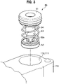
- the check valve 50 is installed in a stepped accommodation chamber 111 having a circular cross section to communicate with the branch supply path 73a.
- the accommodation chamber 111 is open to an end surface of the base body 100.
- the accommodation chamber 111 includes a large-diameter portion 112 having a large diameter, as a first accommodation chamber, and a small-diameter portion 113 having a smaller diameter than the large-diameter portion 112, as a second accommodation chamber.
- the small-diameter portion 113 is formed to have a larger diameter, with a stepped portion 113a as a boundary.
- the small-diameter portion 113 is formed with a flat seat surface 114.
- the seat surface 114 is open, in a radially center thereof, to the branch supply path 73a.
- the branch supply path 73a communicates with the slave cylinder supply path 73.
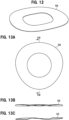
- the plug 52 is a member accommodated in the small-diameter portion 113 of the accommodating chamber 111, and seated on or separated from the seat surface 114 (see FIGS. 14A and 14B ). As shown in FIGS. 4 to 7 , the plug 52 includes a disk-shaped plug base 52a and a cylindrical second extension 52b extending from the plug base 52a toward the cap 51.
- the sealing member 52d includes a base portion 52k, an annular ridge portion 52d1, an annular radially outer portion 52d2, and an annular radially inner portion 52d3.
- the base portion 52k is a portion fixed into the annular groove 52a1.
- the ridge portion 52d1 protrudes, in a rounded mountain shape in cross section, from the base portion 52k toward the seat surface 114 of the accommodation chamber 111.
- the ridge portion 52d1 protrudes with respect to the seating surface 52z of the plug base 52a and works as a sealing point to abut on the seat surface 114 to close the branch supply path 73a.
- the radially outer portion 52d2 has a substantially U-shape in cross section, and is recessed from the seating surface 52z of the plug base 52a toward a direction away from the seat surface 114 of the accommodation chamber 111 (toward a bottom of the annular groove 52a1).
- the radially outer portion 52d2 is adjacent to a radially outer side of the ridge portion 52d1, and an inner end thereof is continuous to the radially outer side of the ridge portion 52d1.
- An outer end of the radially outer portion 52d2 is joined to an outer opening edge 52e of the annular groove 52a1.
- the radially outer portion 52d2 flexibly extends inward in the radial direction when the radially inner portion 52d3 receives brake fluid pressure and is deformed inward in the radial direction, as will be described below.
- the radially inner portion 52d3 is a portion corresponding to a deformed portion to be deformed by brake fluid pressure.
- the radially inner portion 52d3 is deformed radially inward by increased brake fluid pressure, together with the ridge portion 52d1, and bulging toward, and abutting on, the seat surface 114 (see FIG. 11 ).
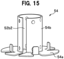
- the cylindrical wall 54b extends toward the plug 52, and is formed to a size of a front end thereof being located radially outside the flange 52c of the second extension 52b (to overlap), as shown in FIGS. 6 and 7 .
- CL1 a clearance between the outer surface of the first extension 51b of the cap 51 and the inner surface of the second extension 52b of the plug 52
- CL2 a clearance between the outer surface of the second extension 52b and the inner surface of the cylindrical wall 54b
- a waved washer 56 as an elastic member is interposed between the cap 51 and the retainer base 54a.
- the waved washer 56 has curved abutting points on surfaces thereof, to have a predetermined spring constant.
- the waved washer 56 when interposed between the cap 51 and the retainer base 54a, biases the retainer base 54a by a spring force toward the plug 52 (spring 53).
- the spring constant of the waved washer 56 is set to be larger than the spring constant of the spring 53.
- the attaching structure is simple to facilitate combining the check valve 50.
- the clearance CL1 between the outer surface of the first extension 51b and the inner surface of the second extension 52b and the clearance CL2 between the outer surface of the second extension 52b and the inner surface of the cylindrical wall 54b have the relationship of CL1 being smaller than CL2 (CL1 ⁇ CL2). This allows for securing a clearance of the inner surface of the cylindrical wall 54b of the retainer 54 not contacting the outer surface of the second extension 52b, when the second extension 52b is slid with respect to the first extension 51b. Accordingly, sliding resistance is reduced to improve response of opening/closing the flow path by the plug 52.
- the sealing point of the sealing member 52d is located radially inner than the abutting point of the spring 53. This allows the plug 52 to be pressed toward the seat surface 114 over a wider area. This secures a sufficient level of the plug 52 being parallel with respect to the flat seat surface 114 in the flow path, to also improve adhesiveness of the sealing member 52d with respect to the seat surface 114. Accordingly, sealing performance of the plug 52 is improved with respect to the seat surface 114.
- the first protrusion 54b1 of the cylindrical wall 54b of the retainer 54 projects from radially outside of the second extension 52b toward the second extension 52b and is locked to the annular surface 52c1, but the invention is not limited thereto.
- the first protrusion 54b1 may be configured to project from radially inside of the second extension 52b toward an inner surface of the second extension 52b and be locked to the second extension 52b.
Landscapes
- Engineering & Computer Science (AREA)
- Mechanical Engineering (AREA)
- Transportation (AREA)
- General Engineering & Computer Science (AREA)
- Physics & Mathematics (AREA)
- Fluid Mechanics (AREA)
- Regulating Braking Force (AREA)
Applications Claiming Priority (5)
| Application Number | Priority Date | Filing Date | Title |
|---|---|---|---|
| JP2020080664A JP7560960B2 (ja) | 2020-04-30 | 2020-04-30 | チェックバルブおよびブレーキシステム |
| JP2020080666A JP7560961B2 (ja) | 2020-04-30 | 2020-04-30 | チェックバルブおよびブレーキシステム |
| JP2020080665A JP7499061B2 (ja) | 2020-04-30 | 2020-04-30 | チェックバルブおよびブレーキシステム |
| JP2020080663A JP7560959B2 (ja) | 2020-04-30 | 2020-04-30 | チェックバルブおよびブレーキシステム |
| PCT/JP2021/016051 WO2021220888A1 (ja) | 2020-04-30 | 2021-04-20 | チェックバルブおよびブレーキシステム |
Publications (2)
| Publication Number | Publication Date |
|---|---|
| EP4144603A1 true EP4144603A1 (de) | 2023-03-08 |
| EP4144603A4 EP4144603A4 (de) | 2024-05-29 |
Family
ID=78331547
Family Applications (1)
| Application Number | Title | Priority Date | Filing Date |
|---|---|---|---|
| EP21796734.8A Pending EP4144603A4 (de) | 2020-04-30 | 2021-04-20 | Rückschlagventil und bremssystem |
Country Status (3)
| Country | Link |
|---|---|
| US (1) | US12472919B2 (de) |
| EP (1) | EP4144603A4 (de) |
| WO (1) | WO2021220888A1 (de) |
Families Citing this family (2)
| Publication number | Priority date | Publication date | Assignee | Title |
|---|---|---|---|---|
| DE102019218481A1 (de) * | 2019-11-28 | 2021-06-02 | Robert Bosch Gmbh | Hydraulikblock für ein Hydraulikaggregat einer hydraulischen Fremdkraft-Fahrzeugbremsanlage |
| KR20250028484A (ko) * | 2022-07-25 | 2025-02-28 | 니토 코키 가부시키가이샤 | 역지 밸브 |
Family Cites Families (29)
| Publication number | Priority date | Publication date | Assignee | Title |
|---|---|---|---|---|
| US4305425A (en) * | 1978-06-19 | 1981-12-15 | Mackal Glenn H | Oral inflation valve |
| US4257443A (en) * | 1978-12-15 | 1981-03-24 | Victor Equipment Company | Check valve |
| JPS5979672U (ja) | 1982-11-19 | 1984-05-29 | 本田技研工業株式会社 | 逆止弁 |
| US4750516A (en) * | 1986-09-19 | 1988-06-14 | General Motors Corporation | Vacuum check valve |
| JPH0535749U (ja) * | 1991-10-11 | 1993-05-14 | 昭和アルミニウム株式会社 | パーソナルケア容器 |
| JP2583167Y2 (ja) | 1992-10-15 | 1998-10-15 | 株式会社小松製作所 | チェックバルブ |
| JPH0635750U (ja) | 1992-10-19 | 1994-05-13 | 株式会社キッツ | 逆止め弁 |
| DE4236481C2 (de) | 1992-10-29 | 1995-07-13 | Bosch Gmbh Robert | Rückschlagventil |
| US5653256A (en) * | 1995-09-28 | 1997-08-05 | Nissan Research & Development, Inc. | Charge valve assembly |
| US5967179A (en) * | 1998-02-02 | 1999-10-19 | Westinghouse Air Brake Company | Low profile discharge check valve |
| DE10015576B4 (de) | 2000-03-29 | 2014-07-10 | Eurocopter Deutschland Gmbh | Anordnung eines Ventils in einer von einem Tankgefäß zu einer oberhalb des Tankgefäßes angeordneten Brennkraftmaschine führenden Treibstoff-Förderleitung |
| DE102004044818A1 (de) * | 2004-09-16 | 2006-03-23 | Robert Bosch Gmbh | Verdichterbypassventil bei mehrstufiger Aufladung |
| US7185671B2 (en) | 2004-12-27 | 2007-03-06 | A. Y. Mcdonald Mfg. Co. | Angled dual check valve |
| US7708025B2 (en) * | 2005-03-07 | 2010-05-04 | Colder Products Company | Poppet valve member |
| US20070193633A1 (en) * | 2006-02-17 | 2007-08-23 | Conbraco Industries, Inc. | Self-contained check valve module |
| JP5000411B2 (ja) * | 2006-08-31 | 2012-08-15 | 日立オートモティブシステムズ株式会社 | マスタシリンダおよびその製造方法 |
| JP2013019442A (ja) | 2011-07-08 | 2013-01-31 | Kitz Corp | 逆止め弁 |
| JP2016044787A (ja) | 2014-08-26 | 2016-04-04 | 株式会社Ihi | バルブとこれを備えた逆止弁付保圧弁 |
| KR102476400B1 (ko) * | 2015-12-04 | 2022-12-12 | 에이치엘만도 주식회사 | 체크밸브 |
| JP6723048B2 (ja) | 2016-03-30 | 2020-07-15 | 日信ブレーキシステムズ株式会社 | 液圧発生装置 |
| KR20180127699A (ko) * | 2017-05-22 | 2018-11-30 | 주식회사 만도 | 체크밸브 |
| KR102602359B1 (ko) * | 2018-11-22 | 2023-11-16 | 에이치엘만도 주식회사 | 체크밸브 및 이를 포함하는 모듈레이터블록 |
| EP4155590A1 (de) * | 2019-03-26 | 2023-03-29 | Pacific Industrial Co., Ltd. | Ventil |
| GB2585035B (en) * | 2019-06-25 | 2023-04-26 | Intersurgical Ag | An adjustable valve |
| US20210215264A1 (en) * | 2020-01-10 | 2021-07-15 | Dayco Ip Holdings, Llc | Hemispherical poppet check valve |
| FR3124567B1 (fr) * | 2021-06-25 | 2026-02-06 | Hutchinson | Dispositif de raccordement fluidique et vanne inserable anti-retour pour vehicule |
| CN215806542U (zh) * | 2021-07-14 | 2022-02-11 | 盾安汽车热管理科技有限公司 | 单向阀及阀岛 |
| KR102550802B1 (ko) * | 2022-09-30 | 2023-07-04 | 주식회사 세명테크 | 상용차의 압축 공기 처리 장치용 언로딩 밸브 장치 |
| KR20240133276A (ko) * | 2023-02-28 | 2024-09-04 | 에이치엘만도 주식회사 | 체크밸브 및 이를 포함하는 브레이크 시스템 |
-
2021
- 2021-04-20 EP EP21796734.8A patent/EP4144603A4/de active Pending
- 2021-04-20 WO PCT/JP2021/016051 patent/WO2021220888A1/ja not_active Ceased
- 2021-04-20 US US17/920,249 patent/US12472919B2/en active Active
Also Published As
| Publication number | Publication date |
|---|---|
| US12472919B2 (en) | 2025-11-18 |
| US20230303049A1 (en) | 2023-09-28 |
| WO2021220888A1 (ja) | 2021-11-04 |
| EP4144603A4 (de) | 2024-05-29 |
Similar Documents
| Publication | Publication Date | Title |
|---|---|---|
| US9499149B2 (en) | Brake hydraulic pressure generator | |
| WO2020116220A1 (ja) | 自動車用ペダルストローク検出装置および自動車用コントロールユニット | |
| JP6046699B2 (ja) | 制動装置 | |
| EP4144603A1 (de) | Rückschlagventil und bremssystem | |
| US20150069828A1 (en) | Pressure regulator and hydraulic brake system equipped with the pressure regulator | |
| JP2016102563A (ja) | ブレーキ装置及び電磁弁 | |
| KR101719443B1 (ko) | 브레이크 장치 및 브레이크 시스템 | |
| US20190217834A1 (en) | Hydraulic Control Apparatus and Brake System | |
| WO2017043269A1 (ja) | 電磁弁、液圧制御装置およびブレーキ装置 | |
| CN101253087B (zh) | 车辆制动系统 | |
| CN107264503B (zh) | 电磁阀、车辆用制动液压控制装置及电磁阀的制造方法 | |
| JP2022072069A (ja) | 液圧発生装置 | |
| EP3002171B1 (de) | Zylindervorrichtung und fahrzeugbremsanlage | |
| RU2053149C1 (ru) | Устройство для регулирования давления в гидравлической тормозной системе автоматического транспортного средства | |
| KR101593867B1 (ko) | 실린더 장치 | |
| JP5943472B2 (ja) | 操作量検出装置 | |
| JP7463253B2 (ja) | 液圧発生装置 | |
| WO2017179496A1 (ja) | ブレーキ装置およびプランジャポンプ | |
| JP7499061B2 (ja) | チェックバルブおよびブレーキシステム | |
| JP7560959B2 (ja) | チェックバルブおよびブレーキシステム | |
| JP7560960B2 (ja) | チェックバルブおよびブレーキシステム | |
| JP7560961B2 (ja) | チェックバルブおよびブレーキシステム | |
| US20230100969A1 (en) | Vehicle braking device | |
| JP6308587B2 (ja) | ブレーキ装置 | |
| JP2022072051A (ja) | 液圧発生装置 |
Legal Events
| Date | Code | Title | Description |
|---|---|---|---|
| STAA | Information on the status of an ep patent application or granted ep patent |
Free format text: STATUS: THE INTERNATIONAL PUBLICATION HAS BEEN MADE |
|
| PUAI | Public reference made under article 153(3) epc to a published international application that has entered the european phase |
Free format text: ORIGINAL CODE: 0009012 |
|
| STAA | Information on the status of an ep patent application or granted ep patent |
Free format text: STATUS: REQUEST FOR EXAMINATION WAS MADE |
|
| 17P | Request for examination filed |
Effective date: 20221125 |
|
| AK | Designated contracting states |
Kind code of ref document: A1 Designated state(s): AL AT BE BG CH CY CZ DE DK EE ES FI FR GB GR HR HU IE IS IT LI LT LU LV MC MK MT NL NO PL PT RO RS SE SI SK SM TR |
|
| DAV | Request for validation of the european patent (deleted) | ||
| DAX | Request for extension of the european patent (deleted) | ||
| A4 | Supplementary search report drawn up and despatched |
Effective date: 20240426 |
|
| RIC1 | Information provided on ipc code assigned before grant |
Ipc: F16J 15/18 20060101ALI20240422BHEP Ipc: F16J 15/16 20060101ALI20240422BHEP Ipc: B60T 8/34 20060101ALI20240422BHEP Ipc: B60T 13/138 20060101ALI20240422BHEP Ipc: B60T 17/00 20060101ALI20240422BHEP Ipc: F16K 15/06 20060101ALI20240422BHEP Ipc: B60T 15/36 20060101AFI20240422BHEP |
|
| RAP1 | Party data changed (applicant data changed or rights of an application transferred) |
Owner name: HITACHI ASTEMO, LTD. |
|
| RAP3 | Party data changed (applicant data changed or rights of an application transferred) |
Owner name: ASTEMO, LTD. |