EP4144705A1 - Herstellungsvorrichtung für poröse glasvorform, herstellungsverfahren für poröse glasvorform und herstellungsverfahren für glasfaserglasvorform - Google Patents
Herstellungsvorrichtung für poröse glasvorform, herstellungsverfahren für poröse glasvorform und herstellungsverfahren für glasfaserglasvorform Download PDFInfo
- Publication number
- EP4144705A1 EP4144705A1 EP21795554.1A EP21795554A EP4144705A1 EP 4144705 A1 EP4144705 A1 EP 4144705A1 EP 21795554 A EP21795554 A EP 21795554A EP 4144705 A1 EP4144705 A1 EP 4144705A1
- Authority
- EP
- European Patent Office
- Prior art keywords
- raw material
- gas
- insulation
- base material
- porous glass
- Prior art date
- Legal status (The legal status is an assumption and is not a legal conclusion. Google has not performed a legal analysis and makes no representation as to the accuracy of the status listed.)
- Pending
Links
Images


Classifications
-
- C—CHEMISTRY; METALLURGY
- C03—GLASS; MINERAL OR SLAG WOOL
- C03B—MANUFACTURE, SHAPING, OR SUPPLEMENTARY PROCESSES
- C03B37/00—Manufacture or treatment of flakes, fibres, or filaments from softened glass, minerals, or slags
- C03B37/01—Manufacture of glass fibres or filaments
- C03B37/012—Manufacture of preforms for drawing fibres or filaments
- C03B37/014—Manufacture of preforms for drawing fibres or filaments made entirely or partially by chemical means, e.g. vapour phase deposition of bulk porous glass either by outside vapour deposition [OVD], or by outside vapour phase oxidation [OVPO] or by vapour axial deposition [VAD]
- C03B37/01413—Reactant delivery systems
-
- C—CHEMISTRY; METALLURGY
- C03—GLASS; MINERAL OR SLAG WOOL
- C03B—MANUFACTURE, SHAPING, OR SUPPLEMENTARY PROCESSES
- C03B37/00—Manufacture or treatment of flakes, fibres, or filaments from softened glass, minerals, or slags
- C03B37/01—Manufacture of glass fibres or filaments
- C03B37/012—Manufacture of preforms for drawing fibres or filaments
- C03B37/014—Manufacture of preforms for drawing fibres or filaments made entirely or partially by chemical means, e.g. vapour phase deposition of bulk porous glass either by outside vapour deposition [OVD], or by outside vapour phase oxidation [OVPO] or by vapour axial deposition [VAD]
- C03B37/018—Manufacture of preforms for drawing fibres or filaments made entirely or partially by chemical means, e.g. vapour phase deposition of bulk porous glass either by outside vapour deposition [OVD], or by outside vapour phase oxidation [OVPO] or by vapour axial deposition [VAD] by glass deposition on a glass substrate, e.g. by inside-, modified-, plasma-, or plasma modified- chemical vapour deposition [ICVD, MCVD, PCVD, PMCVD], i.e. by thin layer coating on the inside or outside of a glass tube or on a glass rod
-
- C—CHEMISTRY; METALLURGY
- C03—GLASS; MINERAL OR SLAG WOOL
- C03B—MANUFACTURE, SHAPING, OR SUPPLEMENTARY PROCESSES
- C03B19/00—Other methods of shaping glass
- C03B19/10—Forming beads
- C03B19/1005—Forming solid beads
- C03B19/106—Forming solid beads by chemical vapour deposition; by liquid phase reaction
-
- C—CHEMISTRY; METALLURGY
- C03—GLASS; MINERAL OR SLAG WOOL
- C03C—CHEMICAL COMPOSITION OF GLASSES, GLAZES OR VITREOUS ENAMELS; SURFACE TREATMENT OF GLASS; SURFACE TREATMENT OF FIBRES OR FILAMENTS MADE FROM GLASS, MINERALS OR SLAGS; JOINING GLASS TO GLASS OR OTHER MATERIALS
- C03C13/00—Fibre or filament compositions
- C03C13/04—Fibre optics, e.g. core and clad fibre compositions
- C03C13/048—Silica-free oxide glass compositions
-
- C—CHEMISTRY; METALLURGY
- C03—GLASS; MINERAL OR SLAG WOOL
- C03B—MANUFACTURE, SHAPING, OR SUPPLEMENTARY PROCESSES
- C03B2207/00—Glass deposition burners
- C03B2207/30—For glass precursor of non-standard type, e.g. solid SiH3F
- C03B2207/32—Non-halide
-
- C—CHEMISTRY; METALLURGY
- C03—GLASS; MINERAL OR SLAG WOOL
- C03B—MANUFACTURE, SHAPING, OR SUPPLEMENTARY PROCESSES
- C03B2207/00—Glass deposition burners
- C03B2207/80—Feeding the burner or the burner-heated deposition site
- C03B2207/81—Constructional details of the feed line, e.g. heating, insulation, material, manifolds, filters
-
- C—CHEMISTRY; METALLURGY
- C03—GLASS; MINERAL OR SLAG WOOL
- C03B—MANUFACTURE, SHAPING, OR SUPPLEMENTARY PROCESSES
- C03B2207/00—Glass deposition burners
- C03B2207/80—Feeding the burner or the burner-heated deposition site
- C03B2207/85—Feeding the burner or the burner-heated deposition site with vapour generated from liquid glass precursors, e.g. directly by heating the liquid
- C03B2207/87—Controlling the temperature
Definitions
- the present invention relates to a porous glass base material manufacturing apparatus, a method for manufacturing porous glass base material, and a method for manufacturing glass base material for optical fiber.
- a method for manufacturing a porous glass fine particle body in which glass particles are deposited on a starting base material such as a glass rod to form soot.
- a starting base material such as a glass rod to form soot.
- the porous glass base material is manufactured, for example, by externally depositing SiO 2 fine particles by the OVD method or the like on a core base material manufactured by the VAD method or the like and sintering the deposited body.
- SiCl 4 silicon tetrachloride
- silicon tetrachloride SiCl 4
- SiCl 4 silicon tetrachloride
- a halogen-free organosilicon compound that does not contain Cl (chlorine) in its molecule is used as a starting material for SiO 2 particles (see, for example, Patent documents 1-4).
- An example of such a halogen-free organic silicon compound is octamethylcyclotetrasiloxane (OMCTS), which is a high-purity organic siloxane available on an industrial scale.
- hydrochloric acid is not discharged. This allows for greater flexibility in the handling of materials for manufacturing apparatus and exhaust. In addition, there is no need to install equipment to recover hydrochloric acid and treat the recovered hydrochloric acid, which is expected to reduce costs.
- OMCTS is expected to have the advantage that the heat of combustion is very large, and the amount of combustible gas such as hydrogen required for combustion can be kept lower than that of the conventional method using SiCl 4 .
- octamethylcyclotetrasiloxane which is the organic siloxane raw material, has a high standard boiling point of 175°C and is prone to re-liquefaction when cooled in the raw material gas pipe.
- the raw material gas pipe is heated at a high temperature using heaters, the power consumption of the heaters becomes large, which increases the cost.
- the present invention has been made in view of the above-mentioned problems, and an object of the present invention is to provide a porous glass base material manufacturing apparatus, a method for manufacturing porous glass base material, and a method for manufacturing glass base material for optical fiber, which can prevent re-liquefaction of the raw material in the organic siloxane raw material typified by octamethylcyclotetrasiloxane (OMCTS).
- OCTS octamethylcyclotetrasiloxane
- a porous glass base material manufacturing apparatus releases gas of organic siloxane raw materials into the flame of a group of burners that moves relative to a starting base material along the longitudinal direction of the starting base material rotating around a rotation axis along the longitudinal direction to form soot of porous glass particles on a surface of the starting base material.
- the porous glass base material manufacturing apparatus is equipped with a vaporizer that vaporizes liquid raw materials containing organic siloxane in a liquid state supplied from a raw material tank to make a raw material mixed gas mixed with raw material gas and carrier gas and a raw material gas pipe that supplies the raw material mixed gas to the burner.
- the raw material gas pipe is insulated and kept warm by double insulation, which is a combination of an inner layer heat-insulation material provided on the outside of the raw material gas pipe and an outer layer heat-insulation material provided on the outside of the inner layer heat-insulation material.
- an insulation material with a heat resistance temperature of 160°C or higher may be used for the inner layer heat-insulation material, and an insulation material with thermal conductivity of 0.05 W/m/K or less (20°C) may be used for the outer layer heat-insulation material.
- the organic siloxane raw material may be octamethylcyclotetrasiloxane (OMCTS).
- the raw material gas pipe may be heated and kept at a temperature of 140-220°C.
- the porous glass base material manufacturing apparatus may be further equipped with a liquid mass flow controller that controls the flow rate of the organic siloxane raw material in the liquid state supplied from the raw material tank to the vaporizer.
- the vaporizer may then mix the organic siloxane raw material with the carrier gas and vaporize the liquid raw material to make the raw material mixed gas, in which the raw material gas and carrier gas are mixed.
- the porous glass base material manufacturing apparatus may be further equipped with a liquid mass flow meter that measures the flow rate of organic siloxane raw material in a liquid state supplied from the raw material tank and a liquid gas mixer that has a control valve that controls the flow rate of liquid raw material based on feedback from the liquid mass flow meter and mixes liquid raw material and carrier gas.
- the vaporizer may then vaporize the liquid raw material mixed with the carrier gas by the liquid gas mixer to make the raw material mixed gas in which the raw material gas and carrier gas are mixed.
- a method for manufacturing porous glass base material comprises: a step of supplying a liquid raw material containing an organic siloxane raw material in a liquid state supplied from a raw material tank to a vaporizer; a step of mixing the liquid raw material of the organic siloxane with a carrier gas in a vaporizer and vaporize the liquid raw material to make the raw material mixed gas in which the raw material gas and the carrier gas are mixed; a step of supplying the raw material mixed gas to a burner via a raw material gas pipe; and a step of forming soot of porous glass particles on the surface of a starting base material by releasing the raw material mixed gas into the flame of the burner that moves relative to the starting base material along the longitudinal direction of the starting base material rotating around a rotation axis along the longitudinal direction.
- the raw material gas pipe is insulated and kept warm by double insulation, which is a combination of an inner layer heat-insulation material provided on the outside of the raw material gas pipe and an outer layer heat-insulation material provided on the outside of
- the method for manufacturing glass base material for optical fiber includes a step of obtaining a porous glass base material by the above-mentioned method for manufacturing porous glass base material and a step of performing dehydration and sintering treatment by heating the porous glass base material in a heating furnace.
- the re-liquefaction of raw material gas of organic siloxane raw materials such as octamethylcyclotetrasiloxane (OMCTS) in the porous glass base material manufacturing apparatus can be prevented.
- FIG. 1 shows a supply flow diagram around a vaporizer according to the first embodiment.
- a raw material liquid 101 is pumped from a raw material tank (not shown), and the flow rate thereof is controlled by a liquid mass flow controller 1.
- the raw material liquid 101 is supplied to a vaporizer 3 through a raw material liquid pipe 2.
- the raw material liquid 101 is made into fine droplets by a carrier gas 102, which is also introduced into the vaporizer 3, and is heated to vaporize the raw material liquid 101 and become a raw material mixed gas 104, which is a mixture of the raw material gas and the carrier gas 102.
- the flow rate of the carrier gas 102 is controlled by the gas mass flow controller 4, and the carrier gas is supplied to the vaporizer 3 through a carrier gas pipe 5.
- the carrier gas 102 may be supplied while being preheated using a heat exchanger 6.
- an inert gas such as nitrogen, argon and helium, oxygen, or a mixed gas of oxygen and the inert gas may be used.
- the raw material mixed gas 104 is supplied to a burner 11 via a raw material gas pipe 10.
- An open/close valve 20 is provided in the raw material liquid pipe 2 immediately before the vaporizer 3, and after the supply of the raw material liquid 101 is completed, the raw material liquid 101 that has accumulated in the open/close valve 20 and piping of the vaporizer 3 is purged with purge gas 105.
- the purge gas pipe 21 is equipped with an open/close valve 22, flow rate control means 23 (e.g., flow rate control valve), and a check valve 24 are provided.
- oxygen as premixed gas 103 may be further mixed with the raw material mixed gas 104 before being supplied to the burner 11.
- the flow rate of the premixed gas 103 is controlled by the gas mass flow controller 7, and the premixed gas 103 is mixed in the raw material gas pipe 10 through a premixed gas pipe 8.
- oxygen, which is the premixed gas 103 may be supplied while being preheated using a heat exchanger 9.
- the temperature of the vaporizer 2 is set to a temperature of 160 °C or more and 220 °C or less when OMCTS is used as the organic siloxane raw material.
- the temperature is low, the vapor pressure of the raw material liquid is lowered, and when the temperature is lower than 160 °C, the vaporization efficiency significantly decreases.
- the temperature exceeds 220 °C, the polymer derived from the raw material liquid 101 may be deposited.
- the raw material gas pipe 10 to the burner 11 downstream of the vaporizer 3 is preferably set at a temperature of 140°C or more and 220°C or less to prevent re-liquefaction and polymerization of the raw material gas in the raw material mixed gas 104. More preferably, the temperature of the vaporizer 3 and the raw material gas pipe 10 should be set to a temperature of 160 °C or more and 190 °C or less. It is preferable that the raw material gas pipe 10 is equipped with a heater to heat it to the desired temperature.
- FIG. 2 illustrates a schematic diagram of the porous glass base material manufacturing apparatus in the first embodiment.
- the burner 11 moves in parallel with the guide mechanism 12 using a traverse motor.
- the starting base material 13 is attached to a rotating mechanism 14 and rotated in a certain direction. While the burner 11 repeatedly moves parallel to the longitudinal direction of the starting base material 13, SiO 2 fine particles are adhered to the starting base material 13 by the raw material gas emitted from the burner 11, and soot deposit 15 is produced.
- the undeposited SiO 2 particles that did not adhere to the soot deposit 15 are discharged out of the system through the exhaust hood 16.
- the exhaust hood 16 can be either a local exhaust structure or a total exhaust structure.
- Each gas pipe supplying the burner 11 moves following the burner 11, which repeatedly moves in parallel.
- the pipe for each gas supplied to the burner 11 should have mobility, and each gas pipe should be housed inside a movable cable protector 17, such as a cableveyor (registered trademark of Tsubakimoto Chain Co.). This allows each gas
- the raw material gas pipe 10 When the raw material gas pipe 10 is housed in the movable cable protector 17 and a heater is used to heat the raw material gas pipe 10, the raw material gas pipe 10 is constantly subjected to tensile and bending stresses. As a result, heaters are more likely to break due to fatigue, and in configurations that use a heat transfer fluid, the heat transfer fluid piping is more likely to break due to fatigue. For this reason, it is preferable to use no heaters in the raw material gas pipe 10 inside the movable cable protector 17, but only heat insulation.
- the amount of heat dissipation can be reduced at the raw material gas pipe 10 sites heated by the heater except in the movable cable protector 17, and the temperature can be maintained constant at low power, contributing to a reduction in the power consumption of the heater.
- Insulation materials for piping must have high thermal insulation performance, high heat resistance temperature, low cost, easy installation, small density, high durability, low dust generation, and flexibility. However, it is difficult to select an insulation material that meets all these requirements.
- octamethylcyclotetrasiloxane which is an organic siloxane raw material, has a high standard boiling point of 175°C. Therefore, a heat-resistant temperature of at least 160°C is required for insulation materials suitable for insulating the raw material gas pipe 10.
- Piping insulation materials with high heat resistance temperatures include rock wool, glass wool, polyimide, and silicone sponge. Rock wool and glass wool have high heat resistance temperatures and high insulation performance but are not suitable for use within the movable cable protector 17.
- Polyimide also has a high heat resistance temperature and high thermal insulation performance but is relatively expensive.
- Silicone sponge tubes have a heat resistance temperature of 200°C, are easy to install, flexible, and highly durable.
- the thermal conductivity is 0.2 W/m/K (20°C), which is higher than that of inorganic insulation materials. Therefore, in the case of insulation only with silicone sponge tubes, the amount of heat dissipation is large, and the raw material gas pipe 10 is easily cooled.
- the possibility of re-liquefaction of the raw material gas in the raw material mixed gas 104 increases in the raw material gas pipe 10 in the moving cable protector 17, where no heater is used, and only heat insulation is preferred.
- the power consumption required to maintain the temperature in the raw material gas pipe 10 in areas where heaters are used is large, which leads to increased costs.
- FIG. 3 shows a cross-sectional view of the heat-insulating structure of the raw material gas pipe 10 in the first embodiment. It has a double heat-insulating structure with an inner layer heat-insulation material 18 covering the raw material gas piping 10 and an outer layer heat-insulation material 19 covering the outside.
- a silicone sponge tube is used as the inner layer heat-insulation material 18, and an insulation material with even lower thermal conductivity is used as the outer layer heat-insulation material 19.
- the outer layer heat-insulation material 19 is not wrapped directly around piping or heaters that are kept at temperatures near 180°C, insulation material with a heat resistance temperature below the surface temperature of the outer layer heat-insulation material 18 can be used. Although it depends on the thickness and thermal conductivity of the inner layer heat-insulation material 18, the heat resistance temperature of the outer layer heat-insulation material 19 is preferably about 120°C.
- the outer layer heat-insulation material 19 for example, AEROFLEX (registered trademark), which is an insulation material with an EPDM (ethylene-propylene-diene rubber) synthetic rubber elastomer structure with an independent bubble structure, may be used.
- FIG. 4 shows a supply flow diagram around the vaporizer according to the second embodiment.
- the raw material liquid 101 is flow-measured by the liquid mass flow meter 25 and fed through the raw material liquid pipe 2 to a liquid gas mixer 26.
- the liquid gas mixer 26 has a control valve that controls the flow rate of the liquid raw material 101.
- the flow rate of the liquid raw material 101 is adjusted by feedback control from the liquid mass flow meter 25.
- the raw material liquid 101 is mixed in the liquid gas mixer 26 with the carrier gas 102, which is also introduced into the liquid gas mixer 26, and heated in the downstream vaporizer 3 to become the raw material mixed gas 104.
- the flow rate of the carrier gas 102 is controlled by the gas mass flow controller 4, and the carrier gas is supplied to the liquid gas mixer 26 through the carrier gas pipe 5.
- an inert gas such as nitrogen, argon and helium, oxygen, or a mixed gas of oxygen and the inert gas may be used.
- the raw material mixed gas 104 is supplied to the burner 11 via the raw material gas pipe 10.
- An open/close valve 20 is provided in the raw material liquid pipe 2 immediately before the liquid gas mixer 26, and after the supply of the raw material liquid 101 is completed, the raw material liquid 101 that has accumulated in the open/close valve 20 and piping of the liquid gas mixer 26 is purged with purge gas 105.
- the purge gas pipe 21 is equipped with an open/close valve 22,
- the purge gas pipe 21 is equipped with an open/close valve 22, flow rate control means 23, and a check valve 24 are provided.
- oxygen as premixed gas 103 may be further mixed with the raw material mixed gas 104 before being supplied to the burner 11.
- the flow rate of the premixed gas 103 is controlled by the gas mass flow controller 7, and the premixed gas 103 is mixed in the raw material gas pipe 10 through the premixed gas pipe 8.
- the raw material gas pipe 10 has a double insulation structure similar to that of the raw material gas pipe in the first embodiment.
- oxygen, which is the premixed gas 103 may be supplied while being preheated using the heat exchanger 9.
- the raw material mixed gas may be further mixed with a carrier gas 106.
- the flow rate of the carrier gas 106 is controlled by the gas mass flow controller 27, and carrier gas 106 is mixed in the raw material gas pipe 10 through a carrier gas pipe 28.
- carrier gas 106 an inert gas such as nitrogen, argon, and helium may be used.
- the carrier gas 106 may also be preheated and supplied using the heat exchanger 9 to prevent re-liquefaction of the raw material mixed gas 104.
- the porous glass base material manufacturing apparatus configured as described above may be combined with a heating furnace for dehydrating and sintering the porous glass base material obtained from the porous glass matrix manufacturing apparatus to constitute an optical fiber base material manufacturing apparatus for obtaining a transparent vitrified optical fiber base material.
- the raw material gas pipe 10 was heated by an electric heater to a temperature of 190°C up to the inlet of the movable cable protector 17. No electric heater was used for the raw material gas pipe 10 housed in the movable cable protector 17, and only heat insulation was used.
- the length of the raw material gas pipe 10 housed within the movable cable protector 17 was 3 [m].
- a 3/8-inch (0.9525 cm) PFA tube was used as the raw material gas pipe 10.
- a double insulation structure was used for heat insulation, with silicone sponge tubes as the inner layer heat-insulation material 18 and Aeroflex as the outer layer heat-insulation material 19.
- the thickness of the silicone sponge tube which is the inner layer heat-insulation material 18, was set to 0.005 [m].
- the thickness Aeroflex which is the outer layer heat-insulation material 19, was set to 0.01 [m].
- the supply flow around the vaporizer was as shown in Fig. 1 .
- OMCTS was used as the raw material liquid 101.
- the space above the raw material liquid in the raw material tank was filled with N 2 , an inert gas.
- the internal pressure of the raw material tank was set at 0.02 MPa by gauge pressure.
- a diaphragm pump was used as the feeding pump, and the discharge pressure of the pump was kept at 0.5 MPa.
- the pressure on the raw material liquid 101 just before vaporizer 3 was set to 0.02-0.3 MPa.
- N 2 was used as carrier gas.
- O 2 was used as the premixed gas 103.
- the flow rate of the raw material mixed gas 104 flowing through the raw material gas pipe 10 was adjusted in the range of 20 to 80 [SLM] and supplied to the burner 11.
- a double insulation structure was used for heat insulation of the raw material gas pipe 10, with silicone sponge tubes as the inner layer heat-insulation material 18 and Aeroflex as the outer layer heat-insulation material 19.
- the thickness of the silicone sponge tube, which is the inner layer heat-insulation material 18, was set to 0.005 [m].
- the thickness Aeroflex, which is the outer layer heat-insulation material 19, was set to 0.01 [m].
- the supply flow around the vaporizer was as shown in Fig. 4 .
- OMCTS was used as the raw material liquid 101.
- the space above the raw material liquid in the raw material tank was filled with N 2 , an inert gas.
- the internal pressure of the raw material tank was set at 0.02 MPa by gauge pressure.
- a diaphragm pump was used as the feeding pump, and the discharge pressure of the pump was kept at 0.5 MPa.
- the pressure on the raw material liquid 101 just before vaporizer 3 was set to 0.02-0.3 MPa.
- N 2 was used as carrier gas.
- O 2 was used as the premixed gas 103.
- the flow rate of the raw material mixed gas 104 flowing through the raw material gas pipe 10 was adjusted in the range of 20 to 80 [SLM] and supplied to the burner 11.
- a single-layer insulation structure was used for heat insulation of the raw material gas pipe 10, with silicone sponge tubes as the insulation material.
- the thickness of the silicone sponge tube was set to 0.005 [m].
- the conditions were the same as in Example 1, except for the heat-insulation structure.
- a single-layer insulation structure was used for heat insulation of the raw material gas pipe 10, with silicone sponge tubes as the insulation material.
- the thickness of the silicone sponge tube was set to 0.015 [m].
- the raw material gas pipe 10 was heated by an electric heater to a temperature of 230°C.
- the conditions were the same as in Example 1.
- the gel was deposited in the raw material gas pipe 10, although no re-liquefaction occurred in the raw material gas pipe 10 or in the burner 11. This is due to the fact that the raw material mixed gas 104 was overheated at a high temperature, resulting in the formation of polymerized products caused by the raw material and impurities contained therein.
- silicone sponge tubes which are the insulation material, were used above the heat resistance temperature, resulting in rapid deterioration of the insulation material.
- Table 1 summarizes the insulation structure, insulation thickness, temperature of the raw material gas pipe 10 at the inlet of the movable cable protector 17, and re-liquefaction/gelation in the raw material gas pipe 10 for Examples 1, 2, and Comparative Examples 1-3.
- Heat-insulating Structure Thickness of Inner Layer Heat-insulation Material 18 [m] Thickness of Outer Layer Heat-insulation Material 19 [m] Temperature at Inlet of Raw Material Gas Pipe 10 [°C] Re-liquefaction/Gelation
- Example 1 Double Insulation 0.005 0.01 190 Not occur
- Example 2 Double Insulation 0.005 0.01 190 Not occur
- Comparative Example 1 Single Insulation 0.005 - 190 Re-liquefaction occurred Comparative Example 2 Single Insulation 0.015 - 190 Re-liquefaction occurred Comparative Example 3 Single Insulation 0.015 - 230 Gelation occurred
- the amount of heat dissipation to the outside air Q is expressed as equation (1) and equation (2).
- the temperature T 3 at the surface of the outer layer heat-insulation material and the amount of heat dissipation Q from the surface of the insulation materials to the outside air can be obtained.
- the temperature T 3 [°C] at the surface of the outer layer heat-insulation material under the same conditions is shown by circular markers in Fig. 6 .
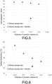
- Fig. 5 shows that the double insulation structure of the silicone sponge tube and Aeroflex has less than half the heat dissipation Q at the same thickness of 0.015 [m] compared to the single insulation structure of the silicone sponge tube.
- Fig. 6 shows that, with respect to the temperature T 3 on the surface of the outer layer heat-insulation material, it is 30 [°C] lower in the double insulation structure than in the single insulation structure at the same thickness of 0.015 [m].
Landscapes
- Chemical & Material Sciences (AREA)
- Engineering & Computer Science (AREA)
- Organic Chemistry (AREA)
- Chemical Kinetics & Catalysis (AREA)
- Materials Engineering (AREA)
- Manufacturing & Machinery (AREA)
- Life Sciences & Earth Sciences (AREA)
- General Chemical & Material Sciences (AREA)
- Geochemistry & Mineralogy (AREA)
- General Life Sciences & Earth Sciences (AREA)
- Optics & Photonics (AREA)
- Physics & Mathematics (AREA)
- Glass Melting And Manufacturing (AREA)
- Manufacture, Treatment Of Glass Fibers (AREA)
Applications Claiming Priority (2)
| Application Number | Priority Date | Filing Date | Title |
|---|---|---|---|
| JP2020081549 | 2020-05-01 | ||
| PCT/JP2021/014742 WO2021220747A1 (ja) | 2020-05-01 | 2021-04-07 | 多孔質ガラス母材製造装置、多孔質ガラス母材の製造方法、および光ファイバ用ガラス母材の製造方法 |
Publications (2)
| Publication Number | Publication Date |
|---|---|
| EP4144705A1 true EP4144705A1 (de) | 2023-03-08 |
| EP4144705A4 EP4144705A4 (de) | 2024-05-01 |
Family
ID=78373496
Family Applications (1)
| Application Number | Title | Priority Date | Filing Date |
|---|---|---|---|
| EP21795554.1A Pending EP4144705A4 (de) | 2020-05-01 | 2021-04-07 | Herstellungsvorrichtung für poröse glasvorform, herstellungsverfahren für poröse glasvorform und herstellungsverfahren für glasfaserglasvorform |
Country Status (6)
| Country | Link |
|---|---|
| US (2) | US12371364B2 (de) |
| EP (1) | EP4144705A4 (de) |
| JP (1) | JP7450023B2 (de) |
| KR (1) | KR102913527B1 (de) |
| CN (1) | CN115485246A (de) |
| WO (1) | WO2021220747A1 (de) |
Families Citing this family (1)
| Publication number | Priority date | Publication date | Assignee | Title |
|---|---|---|---|---|
| CN117412929B (zh) * | 2021-12-22 | 2026-02-06 | 住友电气工业株式会社 | 玻璃微粒沉积体的制造装置以及制造方法 |
Family Cites Families (16)
| Publication number | Priority date | Publication date | Assignee | Title |
|---|---|---|---|---|
| WO1999003787A1 (en) * | 1997-07-21 | 1999-01-28 | Corning Incorporated | Methods and apparatus for producing low flow rates of feedstock vapors |
| JP2000220790A (ja) | 1999-02-02 | 2000-08-08 | Tsuzuki:Kk | 断熱材 |
| JP4358088B2 (ja) * | 2004-01-14 | 2009-11-04 | 株式会社フジクラ | 光ファイバ用多孔質ガラス母材の製造装置 |
| KR100651453B1 (ko) * | 2005-10-21 | 2006-11-29 | 삼성전자주식회사 | 수트 모재의 제조 장치 |
| JP2009067604A (ja) | 2007-09-10 | 2009-04-02 | Sumitomo Electric Ind Ltd | ガラス微粒子堆積体の製造装置 |
| WO2009107858A1 (en) | 2008-02-26 | 2009-09-03 | Asahi Glass Co., Ltd. | Tio2-containing silica glass and optical member for euv lithography using high energy densities as well as special temperature controlled process for its manufacture |
| JP5793834B2 (ja) | 2010-07-15 | 2015-10-14 | 住友電気工業株式会社 | ガラス微粒子堆積体製造方法およびガラス体製造方法 |
| EP2418080B9 (de) | 2010-08-13 | 2015-01-21 | Armacell Enterprise GmbH & Co. KG | Flexibles Isoliersystem für hohe Temperaturen |
| DE102011119373A1 (de) | 2011-11-25 | 2013-05-29 | Heraeus Quarzglas Gmbh & Co. Kg | Verfahren zur Herstellung von synthetischem Quarzglas |
| DE102011121190A1 (de) | 2011-12-16 | 2013-06-20 | Heraeus Quarzglas Gmbh & Co. Kg | OMCTS-Verdampfungsverfahren |
| JP2013177297A (ja) | 2012-02-09 | 2013-09-09 | Asahi Glass Co Ltd | ドープ石英ガラスの製造方法 |
| JP2017036172A (ja) | 2015-08-07 | 2017-02-16 | 株式会社フジクラ | 光ファイバ母材の製造方法 |
| JP6700095B2 (ja) | 2016-04-27 | 2020-05-27 | 株式会社フジクラ | ガラス母材の製造方法及び製造装置 |
| CN105953029B (zh) * | 2016-06-14 | 2018-12-07 | 无锡新辉龙科技有限公司 | 一种用于柔性管道加热的复合保温材料 |
| JP6978991B2 (ja) * | 2018-08-23 | 2021-12-08 | 信越化学工業株式会社 | 光ファイバ用多孔質ガラス母材の製造方法および製造装置 |
| JP6943911B2 (ja) * | 2019-03-07 | 2021-10-06 | 古河電気工業株式会社 | 気化器の洗浄方法および気化装置 |
-
2021
- 2021-04-07 JP JP2022517588A patent/JP7450023B2/ja active Active
- 2021-04-07 KR KR1020227033515A patent/KR102913527B1/ko active Active
- 2021-04-07 US US17/921,751 patent/US12371364B2/en active Active
- 2021-04-07 EP EP21795554.1A patent/EP4144705A4/de active Pending
- 2021-04-07 WO PCT/JP2021/014742 patent/WO2021220747A1/ja not_active Ceased
- 2021-04-07 CN CN202180031626.7A patent/CN115485246A/zh active Pending
-
2025
- 2025-07-02 US US19/258,157 patent/US20250388505A1/en active Pending
Also Published As
| Publication number | Publication date |
|---|---|
| US12371364B2 (en) | 2025-07-29 |
| US20250388505A1 (en) | 2025-12-25 |
| JP7450023B2 (ja) | 2024-03-14 |
| WO2021220747A1 (ja) | 2021-11-04 |
| EP4144705A4 (de) | 2024-05-01 |
| JPWO2021220747A1 (de) | 2021-11-04 |
| KR20230004461A (ko) | 2023-01-06 |
| KR102913527B1 (ko) | 2026-01-15 |
| CN115485246A (zh) | 2022-12-16 |
| US20230167004A1 (en) | 2023-06-01 |
Similar Documents
| Publication | Publication Date | Title |
|---|---|---|
| EP3109342B1 (de) | Verfahren zur herstellung eines wärmebeständigen verbundstoffes | |
| US11155488B2 (en) | Apparatus and method for manufacturing porous glass preform for optical fiber | |
| US20250388505A1 (en) | Porous glass base material manufacturing apparatus, method for manufacturing porous glass base material, and method for manufacturing glass base material for optical fiber | |
| CN104619881A (zh) | 耐热复合材料的制造方法及制造装置 | |
| US9480959B2 (en) | Process and apparatus for conversion of silicon tetrachloride to trichlorosilane | |
| CN1195691C (zh) | 通过分解有机硅烷生产二氧化硅的方法 | |
| EP0908418B1 (de) | Verfahren zur Herstellung von synthetischem Quarzglas | |
| US5250278A (en) | Method for producing a ceramic product | |
| EP3878823B1 (de) | Verfahren zur herstellung eines porösen glasbasismaterials für eine optische faser | |
| CN117550786B (zh) | 一种增体混合单元、气态原料供料装置及供料方法 | |
| JP6746528B2 (ja) | 光ファイバ多孔質母材の製造装置 | |
| US20240217857A1 (en) | Porous glass base material manufacturing system and method for manufacturing glass base material | |
| JP2955787B2 (ja) | 石英ガラス系光ファイバの製造法 | |
| KR101033165B1 (ko) | 폴리실리콘 증착장치 | |
| CN121342322A (zh) | 一种cvd法制备多孔不透明高纯石英的装置及方法 |
Legal Events
| Date | Code | Title | Description |
|---|---|---|---|
| STAA | Information on the status of an ep patent application or granted ep patent |
Free format text: STATUS: THE INTERNATIONAL PUBLICATION HAS BEEN MADE |
|
| PUAI | Public reference made under article 153(3) epc to a published international application that has entered the european phase |
Free format text: ORIGINAL CODE: 0009012 |
|
| STAA | Information on the status of an ep patent application or granted ep patent |
Free format text: STATUS: REQUEST FOR EXAMINATION WAS MADE |
|
| 17P | Request for examination filed |
Effective date: 20221103 |
|
| AK | Designated contracting states |
Kind code of ref document: A1 Designated state(s): AL AT BE BG CH CY CZ DE DK EE ES FI FR GB GR HR HU IE IS IT LI LT LU LV MC MK MT NL NO PL PT RO RS SE SI SK SM TR |
|
| A4 | Supplementary search report drawn up and despatched |
Effective date: 20240404 |
|
| RIC1 | Information provided on ipc code assigned before grant |
Ipc: C03B 37/018 20060101ALI20240327BHEP Ipc: C03B 8/04 20060101AFI20240327BHEP |
|
| STAA | Information on the status of an ep patent application or granted ep patent |
Free format text: STATUS: EXAMINATION IS IN PROGRESS |
|
| 17Q | First examination report despatched |
Effective date: 20250729 |