EP4144868B1 - Stahlherstellungslinie und verfahren zur herstellung von reduziertem eisen - Google Patents
Stahlherstellungslinie und verfahren zur herstellung von reduziertem eisen Download PDFInfo
- Publication number
- EP4144868B1 EP4144868B1 EP21797227.2A EP21797227A EP4144868B1 EP 4144868 B1 EP4144868 B1 EP 4144868B1 EP 21797227 A EP21797227 A EP 21797227A EP 4144868 B1 EP4144868 B1 EP 4144868B1
- Authority
- EP
- European Patent Office
- Prior art keywords
- gas
- furnace
- reducing
- methane
- blast furnace
- Prior art date
- Legal status (The legal status is an assumption and is not a legal conclusion. Google has not performed a legal analysis and makes no representation as to the accuracy of the status listed.)
- Active
Links
Images



Classifications
-
- C—CHEMISTRY; METALLURGY
- C21—METALLURGY OF IRON
- C21B—MANUFACTURE OF IRON OR STEEL
- C21B5/00—Making pig-iron in the blast furnace
- C21B5/001—Injecting additional fuel or reducing agents
-
- C—CHEMISTRY; METALLURGY
- C21—METALLURGY OF IRON
- C21B—MANUFACTURE OF IRON OR STEEL
- C21B13/00—Making spongy iron or liquid steel, by direct processes
- C21B13/0073—Selection or treatment of the reducing gases
-
- C—CHEMISTRY; METALLURGY
- C21—METALLURGY OF IRON
- C21B—MANUFACTURE OF IRON OR STEEL
- C21B5/00—Making pig-iron in the blast furnace
-
- C—CHEMISTRY; METALLURGY
- C21—METALLURGY OF IRON
- C21B—MANUFACTURE OF IRON OR STEEL
- C21B5/00—Making pig-iron in the blast furnace
- C21B5/06—Making pig-iron in the blast furnace using top gas in the blast furnace process
-
- C—CHEMISTRY; METALLURGY
- C21—METALLURGY OF IRON
- C21B—MANUFACTURE OF IRON OR STEEL
- C21B7/00—Blast furnaces
- C21B7/002—Evacuating and treating of exhaust gases
-
- F—MECHANICAL ENGINEERING; LIGHTING; HEATING; WEAPONS; BLASTING
- F27—FURNACES; KILNS; OVENS; RETORTS
- F27D—DETAILS OR ACCESSORIES OF FURNACES, KILNS, OVENS OR RETORTS, IN SO FAR AS THEY ARE OF KINDS OCCURRING IN MORE THAN ONE KIND OF FURNACE
- F27D17/00—Arrangements for using waste heat; Arrangements for using, or disposing of, waste gases
- F27D17/20—Arrangements for treatment or cleaning of waste gases
-
- C—CHEMISTRY; METALLURGY
- C21—METALLURGY OF IRON
- C21B—MANUFACTURE OF IRON OR STEEL
- C21B5/00—Making pig-iron in the blast furnace
- C21B5/001—Injecting additional fuel or reducing agents
- C21B2005/005—Selection or treatment of the reducing gases
-
- C—CHEMISTRY; METALLURGY
- C21—METALLURGY OF IRON
- C21B—MANUFACTURE OF IRON OR STEEL
- C21B2100/00—Handling of exhaust gases produced during the manufacture of iron or steel
- C21B2100/20—Increasing the gas reduction potential of recycled exhaust gases
- C21B2100/22—Increasing the gas reduction potential of recycled exhaust gases by reforming
-
- C—CHEMISTRY; METALLURGY
- C21—METALLURGY OF IRON
- C21B—MANUFACTURE OF IRON OR STEEL
- C21B2100/00—Handling of exhaust gases produced during the manufacture of iron or steel
- C21B2100/20—Increasing the gas reduction potential of recycled exhaust gases
- C21B2100/26—Increasing the gas reduction potential of recycled exhaust gases by adding additional fuel in recirculation pipes
-
- C—CHEMISTRY; METALLURGY
- C21—METALLURGY OF IRON
- C21B—MANUFACTURE OF IRON OR STEEL
- C21B2100/00—Handling of exhaust gases produced during the manufacture of iron or steel
- C21B2100/20—Increasing the gas reduction potential of recycled exhaust gases
- C21B2100/28—Increasing the gas reduction potential of recycled exhaust gases by separation
- C21B2100/282—Increasing the gas reduction potential of recycled exhaust gases by separation of carbon dioxide
-
- C—CHEMISTRY; METALLURGY
- C21—METALLURGY OF IRON
- C21B—MANUFACTURE OF IRON OR STEEL
- C21B2100/00—Handling of exhaust gases produced during the manufacture of iron or steel
- C21B2100/40—Gas purification of exhaust gases to be recirculated or used in other metallurgical processes
- C21B2100/44—Removing particles, e.g. by scrubbing, dedusting
-
- C—CHEMISTRY; METALLURGY
- C21—METALLURGY OF IRON
- C21B—MANUFACTURE OF IRON OR STEEL
- C21B2100/00—Handling of exhaust gases produced during the manufacture of iron or steel
- C21B2100/60—Process control or energy utilisation in the manufacture of iron or steel
- C21B2100/64—Controlling the physical properties of the gas, e.g. pressure or temperature
-
- C—CHEMISTRY; METALLURGY
- C21—METALLURGY OF IRON
- C21B—MANUFACTURE OF IRON OR STEEL
- C21B2100/00—Handling of exhaust gases produced during the manufacture of iron or steel
- C21B2100/80—Interaction of exhaust gases produced during the manufacture of iron or steel with other processes
-
- Y—GENERAL TAGGING OF NEW TECHNOLOGICAL DEVELOPMENTS; GENERAL TAGGING OF CROSS-SECTIONAL TECHNOLOGIES SPANNING OVER SEVERAL SECTIONS OF THE IPC; TECHNICAL SUBJECTS COVERED BY FORMER USPC CROSS-REFERENCE ART COLLECTIONS [XRACs] AND DIGESTS
- Y02—TECHNOLOGIES OR APPLICATIONS FOR MITIGATION OR ADAPTATION AGAINST CLIMATE CHANGE
- Y02P—CLIMATE CHANGE MITIGATION TECHNOLOGIES IN THE PRODUCTION OR PROCESSING OF GOODS
- Y02P10/00—Technologies related to metal processing
- Y02P10/10—Reduction of greenhouse gas [GHG] emissions
- Y02P10/122—Reduction of greenhouse gas [GHG] emissions by capturing or storing CO2
-
- Y—GENERAL TAGGING OF NEW TECHNOLOGICAL DEVELOPMENTS; GENERAL TAGGING OF CROSS-SECTIONAL TECHNOLOGIES SPANNING OVER SEVERAL SECTIONS OF THE IPC; TECHNICAL SUBJECTS COVERED BY FORMER USPC CROSS-REFERENCE ART COLLECTIONS [XRACs] AND DIGESTS
- Y02—TECHNOLOGIES OR APPLICATIONS FOR MITIGATION OR ADAPTATION AGAINST CLIMATE CHANGE
- Y02P—CLIMATE CHANGE MITIGATION TECHNOLOGIES IN THE PRODUCTION OR PROCESSING OF GOODS
- Y02P10/00—Technologies related to metal processing
- Y02P10/10—Reduction of greenhouse gas [GHG] emissions
- Y02P10/143—Reduction of greenhouse gas [GHG] emissions of methane [CH4]
Definitions
- the present disclosure relates to a steelmaking line and a method of producing reduced iron using the steelmaking line.
- Main raw material of iron is iron oxide, and a reduction process of reducing iron oxide is essential in steelworks.
- a typical reduction process most commonly used in the world is a blast furnace.
- coke and pulverized coal are reacted with oxygen in hot air (air heated to about 1200 °C) in a tuyere to generate CO and H 2 gases (reducing gas), and iron ore and the like in the furnace are reduced using the reducing gas.
- the reducing agent rate (the amount of coke and pulverized coal used per 1 t of hot metal production) has been reduced to about 500 kg/t. Further significant reduction of the reducing agent rate cannot be expected as the reduction of the reducing agent rate has reached its limit.
- the generated reducing gas is blown into the reducing furnace and reacts with the iron oxide raw material supplied from the upper part of the reducing furnace, as a result of which the iron oxide is reduced and the reduced iron is produced.
- the produced reduced iron is discharged from the lower part of the reducing furnace.
- the gas that has been used to reduce the iron oxide is discharged from the furnace top of the reducing furnace as the furnace top gas and subjected to dust collection and cooling. After this, part of the furnace top gas is fed into the reformer as raw material of reformed gas, and the remaining furnace top gas is used as fuel gas in the heat-reformer.
- JP 2017-88912 A (PTL 1) describes a method of reforming exhaust gas of a reducing furnace and natural gas in a reformer to generate reducing gas mainly composed of CO and H 2 gases and blowing the reducing gas into the reducing furnace to reduce iron oxide in the reducing furnace and produce reduced iron.
- JP 6190522 B2 (PTL 2) describes a method of reforming coke oven gas and furnace top gas of a reducing furnace from which CO 2 has been removed to generate reducing gas and blowing the reducing gas into the reducing furnace to produce reduced iron.
- Patent documents US 6 045 602 A , US 2014/202285 A1 and EP 2 543 743 B1 also disclose a method of producing reduced iron while recycling top gas from a reducing furnace.
- the reduced iron production method described in PTL 1 uses natural gas for reducing gas production, and therefore CO 2 emissions are unavoidable to a certain degree although it is less than that of the blast furnace.
- coke oven gas or converter gas is essential as fuel gas in downstream processes such as a heating furnace and an annealing furnace.
- Using such gas in the reduced iron production process causes lack of fuel gas in the downstream processes.
- natural gas needs to be supplied from outside. This makes it impossible to reduce CO 2 emissions.
- the method described in PTL 2 reforms coke oven gas as raw material to obtain reducing gas.
- the coke oven gas because of its high sulfur content, may damage a catalyst accompanying a line involving reaction, such as a reformer. It is considered that appropriate operation in the reduced iron production process is possible if the ratio of H 2 and CO is approximately 1.5.
- Converter gas has low H 2 content, and accordingly the value of H 2 /CO in the reducing gas generated from the converter gas is excessively low, and does not meet the appropriate operating composition for the reduced iron production process. To avoid this, CO 2 needs to be separated from the converter gas, which requires extra energy for CO 2 separation.
- FIG. 1 illustrates an example of our steelmaking line.
- reference sign 1 is a reducing furnace
- 2 is iron oxide
- 3 is reduced iron
- 4 is a dust remover for furnace top gas from the reducing furnace 1
- 5 is a supply path of the furnace top gas
- 6 is a heat-reformer that heats or heat-reforms methane gas from the below-described methane synthesizer and/or carbon monoxide gas to generate reducing gas containing carbon monoxide gas and hydrogen gas
- 7a is a first dehydrator
- 7b is a second dehydrator
- 7c is a third dehydrator
- 8 is a carbon dioxide separator that separates carbon dioxide from the furnace top gas
- 9 is a methane synthesizer that synthesizes methane from the furnace top gas and/or blast furnace gas
- 10 is a reducing gas blower that supplies the reducing gas into the reducing furnace 1
- 21 is a blast furnace
- 22 is a methan
- Our method of producing reduced iron uses this steelmaking line partly or wholly to produce reduced iron according to various modes, and roughly comprises: charging iron oxide into the reducing furnace; blowing reducing gas into the reducing furnace; synthesizing methane from mixed gas containing carbon dioxide and carbon monoxide or carbon dioxide gas, and hydrogen gas; heating raw material gas including the methane gas and the mixed gas and reforming the raw material gas to the reducing gas; and reducing the iron oxide by the reducing gas in the reducing furnace.
- the "reducing furnace” herein denotes a process of reducing charged iron oxide raw material in a solid state and discharging reduced iron, and does not include a process of producing iron melted at high temperature as in a blast furnace.
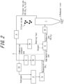
- FIG. 2 selectively illustrates the components used in Embodiment 1 from the components illustrated in FIG. 1 .
- the steelmaking line illustrated in FIG. 1 is used in Embodiment 1.
- reduced iron is produced according to the following procedure: First, the iron oxide 2 is charged into the reducing furnace 1 which is central to the reduced iron production process from its upper part, and the iron oxide 2 is gradually lowered. While lowering the iron oxide 2, high-temperature reducing gas containing CO, H 2 , and hydrocarbon is blown from the reducing gas blower 10 into the reducing furnace 1 at its intermediate part to reduce the iron oxide 2, and the reduced iron 3 is discharged from the lower part of the reducing furnace 1. In this reduction process in the reducing furnace 1, furnace top gas mainly containing CO, CO 2 , H 2 , and H 2 O is discharged from the upper part of the reducing furnace 1. The furnace top gas is subjected to dust removal in the dust remover 4.
- part of the furnace top gas is moisture controlled in the second dehydrator 7b and fed into the heat-reformer 6 as raw material gas.
- the remaining furnace top gas is dehydrated in the first dehydrator 7a, and then used as heating fuel in a combustion chamber in the heat-reformer 6.
- combustion-supporting gas when combusting the furnace top gas in the combustion chamber in the heat-reformer 6 not air but oxygen gas is preferably used to prevent nitrogen from being mixed in.
- hydrocarbon gas for adjusting the furnace top gas components (CO, CO 2 , H 2 , and H 2 O) to the reducing components (CO, H 2 , and hydrocarbon) needs to be supplied into the heat-reformer 6 together with the furnace top gas.
- natural gas is supplied from outside as such hydrocarbon gas, as mentioned above.
- combustion exhaust gas from the combustion chamber in the heat-reformer 6 is used as illustrated in FIG. 2 .
- combustion exhaust gas generated when combusting the furnace top gas in the combustion chamber in the heat-reformer 6 preferably together with oxygen gas as the combustion-supporting gas is dehydrated in the fourth dehydrator 7d and then supplied into the methane synthesizer 9 together with hydrogen, to synthesize methane.
- the synthesized regenerative methane is supplied into the heat-reformer 6 together with the furnace top gas as the raw material gas that has been moisture controlled in the second dehydrator 7b, and heated in the heat-reformer 6.
- the resultant high-temperature reducing gas is then supplied into the reducing furnace 1.
- the furnace top gas used as the raw material gas is moisture controlled to appropriately adjust the composition of the reducing gas.
- the furnace top gas may also be subjected to CO 2 separation in the carbon dioxide separator 8.
- the regenerative methane and the furnace top gas are used as the raw material gas of the reducing gas, water or water vapor may be added for composition adjustment.
- a mechanism for promoting reaction, such as a catalyst, may be provided in the heat-reformer 6 to cause reforming reaction and generate reformed gas mainly containing CO and H 2 .
- only heating may be performed in the heat-reformer and the heated gas may be directly blown into the reducing furnace.
- CO 2 -rich gas after the separation can be used as the raw material gas in the methane synthesizer 9.
- the remaining gas including combustible gas such as CO may be used as fuel gas in the heat-reformer 6 or supplied to another process in the steelworks and used as fuel gas or the like.
- CO 2 -free hydrogen supplied from outside such as hydrogen gas generated by electrolyzing water by solar power
- the oxygen gas used as the combustion-supporting gas in the combustion chamber in the heat-reformer 6 need not necessarily be pure oxygen with an oxygen concentration of 100 %, and may contain a small amount of gas other than oxygen, such as nitrogen, carbon dioxide, and argon. If the oxygen concentration is excessively low, the gas volume increases, and the heat-reformer 6 and the methane synthesizer 9 for performing methane synthesis need to be increased in size. Therefore, the oxygen concentration is preferably 80 % or more.
- CO 2 -free power for oxygen production and hydrogen production CO 2 emissions can be in principle reduced to zero. Examples of the CO 2 -free power that can be used include solar-generated power and nuclear-generated power.
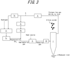
- Embodiment 2 is illustrated in FIG. 3 .
- the furnace top gas used for heating in the heat-reformer 6 in Embodiment 1 is moisture controlled in a dehydrator 7e and then fed into the methane synthesizer 9 as raw material of regenerative methane gas (regenerative CH 4 in FIG. 3 ), to synthesize a necessary amount of regenerative methane for the heat-reformer 6.
- an external CO 2 -free heat source such as an external heat source for heating using CO 2 -free power, may be used as a substitute.
- CO 2 emissions can be in principle reduced to zero.
- Embodiments 1 and 2 described above if a small amount of unwanted gas, such as nitrogen gas for purging, other than CO, CO 2 , H 2 , H 2 O, and hydrocarbon is mixed in, the unwanted gas gradually accumulates in the reduced iron production process and the reducing gas concentration decreases.
- the nitrogen concentration in the system it is desirable to regularly monitor the nitrogen concentration in the system and, if the nitrogen concentration increases to a certain level, e.g. 20 % or more, temporarily discharge, to outside the system, the furnace top gas or the combustion exhaust gas flowing into the methane synthesizer 9. Since the regenerative methane gas cannot be generated during this period, natural gas or the like may be temporarily blown into the heat-reformer 6 instead of the regenerative methane gas.
- the hydrogen gas supplied from outside as raw material for methane synthesis is preferably produced by a method that causes as little CO 2 as possible.
- An example of such a method is electrolysis of water.
- the H 2 gas need not necessarily have a H 2 concentration of 100 %, but higher H 2 concentration is better in order to maintain high methane concentration in the generated regenerative methane gas.
- the H 2 concentration is preferably 80 vol% or more.
- Embodiment 3 will be described below, with reference to FIG. 1 .
- Embodiment 3 describes a method that is advantageous in the case of providing our reduced iron production process in a steelworks including a blast furnace for producing hot metal.
- the furnace top gas discharged from the furnace top of the reducing furnace 1 is subjected to dust removal in the dust remover 4, and subsequently part of the furnace top gas is moisture controlled in the second dehydrator 7b and fed into the heat-reformer 6 as raw material gas and the remaining furnace top gas is dehydrated in the first dehydrator 7a and then used as heating fuel in the combustion chamber in the heat-reformer 6, as illustrated in FIG. 1 as an example.
- Embodiment 3 has a feature that not only the furnace top gas used in Embodiment 2 but also the blast furnace gas discharged from the blast furnace 21 is used as raw material for methane synthesis in the methane synthesizer 9, instead of using the combustion exhaust gas from the heat-reformer 6 as in Embodiment 1.
- a blast furnace operation method in Embodiment 3 will be described below.
- blast furnace operation method in Embodiment 3 sintered ore, lump ore, or pellets (hereafter also referred to as “ore raw material”) as raw material, coke, and the like are charged (not illustrated) into the blast furnace 21 from the furnace top. Moreover, blast gas, a reducing agent, and regenerative methane gas are blown into the blast furnace 21 from a blower (tuyere) 22 installed in the lower part of the blast furnace 21.
- the reducing agent blown into the blast furnace 21 from the blower 22 is also referred to as "blown reducing agent", to distinguish it from coke.
- the ore raw material charged into the blast furnace 21 is then reduced by carbon monoxide gas and hydrogen gas generated as a result of the blast gas and the reducing agent reacting with each other.
- carbon dioxide is generated, and discharged from the furnace top of the blast furnace as by-product gas together with carbon monoxide, hydrogen, etc. unreacted with the ore raw material.
- the furnace top of the blast furnace 21 is in high pressure conditions of about 2.5 atm, water vapor condenses as a result of expansion cooling when the blast furnace gas (by-product gas) discharged from the furnace top of the blast furnace returns to normal pressure, and the condensed water is removed in the dehydrator 23.
- the blast furnace gas is introduced into the methane synthesizer 9.
- carbon monoxide and carbon dioxide contained in the blast furnace gas are reacted with hydrogen gas to generate methane (CH 4 ) gas.
- the methane gas obtained by the reaction of the blast furnace gas is referred to as "regenerative methane gas" (regenerative CH 4 in FIG. 1 ).
- regenerative methane gas regenerative CH 4 in FIG. 1
- water vapor in the regenerative methane gas is condensed, and the by-product water is removed in the third dehydrator 7c.
- the by-product water is preferably supplied to a water electrolyzer and used for water electrolysis, as mentioned above.
- At least part of the blast furnace gas supplied into the methane synthesizer 9 may not maintain the composition when discharged from the blast furnace.
- carbon dioxide may be separated by a carbon dioxide gas separation and recovery device and the separated carbon dioxide alone may be supplied to the methane synthesizer.
- the regenerative methane gas thus obtained is supplied into the heat-reformer 6 together with the furnace top gas as raw material gas, and heating is performed in the heat-reformer 6 to generate high-temperature reducing gas, which is then supplied to the reducing furnace 1.
- Part of the regenerative methane gas is preferably supplied into the blower 22 as a blown reducing agent.
- the regenerative methane gas as the blown reducing agent, the usage of other blown reducing agents such as pulverized coal, waste plastic, and reducing gas such as hydrogen gas and carbon monoxide gas can be reduced.
- the total amount of the blown reducing agents including the regenerative methane gas and the other blown reducing agents blown into the blast furnace is preferably 150 kg/t or less.
- the unit "kg/t" expresses the amount of the other blown reducing agents blown into the blast furnace to produce 1 t of hot metal.
- the hydrogen gas used to generate the regenerative methane gas is not limited to having a hydrogen concentration of 100 vol%, but preferably has high hydrogen concentration, specifically, a hydrogen concentration of 80 vol% or more, to achieve high methane concentration in the regenerative methane gas.
- the hydrogen concentration is more preferably 90 vol% or more, and further preferably 95 vol% or more.
- Examples of residual gases other than hydrogen include CO, CO 2 , H 2 S, CH 4 , and N 2 .
- At least part of the hydrogen gas used in the generation of the regenerative methane gas is preferably hydrogen gas generated by water electrolysis in the water electrolyzer.
- by-product water generated secondarily in the regenerative methane gas generation process can be used as water in the water electrolysis; and by-product oxygen gas generated secondarily in the water electrolysis can be used as oxygen gas serving as blast gas in the tuyere 22.
- Combining these features with the blast furnace operation conditions i.e. use of oxygen gas as blast gas and use of regenerative methane gas as a reducing agent
- the by-product water is used as the water used in the water electrolysis, as mentioned above. If there is lack of water, water is supplied from within the steelworks as appropriate.
- the by-product oxygen gas may be supplied to another oxygen-use line (for example, a converter, an electric heating furnace, a combustion device (heating furnace burner, sintering ignition burner), etc.) depending on the supply amount.
- another oxygen-use line for example, a converter, an electric heating furnace, a combustion device (heating furnace burner, sintering ignition burner), etc.
- Examples of the hydrogen gas supply source in the steelworks include coke oven gas (by-product gas discharged from a coke oven).
- coke oven gas by-product gas discharged from a coke oven.
- a method of separating and recovering hydrogen from the coke oven gas by physical adsorption (PSA) or the like or a method of reforming (partially oxidizing) hydrocarbon in the coke oven gas and separating and recovering hydrogen from the reformed gas by PSA or the like may be used.
- Examples of the hydrogen gas supplied from outside include hydrogen gas obtained by reforming hydrocarbon such as natural gas by water vapor reforming or the like, hydrogen gas obtained by vaporizing liquefied hydrogen, and hydrogen gas obtained by dehydrogenating organic hydride.
- the power used in the water electrolysis is not limited, but is preferably power derived from renewable energy or power generated in a power generation line in the steelworks.
- renewable energy In the case of using power derived from renewable energy, carbon dioxide emissions can be further reduced.
- renewable energy herein denotes energy that constantly exists in the natural world, such as solar power, wind power, hydropower, geothermal power, and biomass.
- the power generation line in the steelworks include a furnace top pressure power generation line for the blast furnace and a power generation line using blast furnace gas as fuel (heat source).
- a blast furnace gas as fuel
- coke oven gas coke oven gas
- converter gas by-product gas discharged from the converter
- city gas may be used as fuel depending on the blast furnace operation state.
- the blown reducing agent such as the regenerative methane gas and the oxygen gas are mixed in the blower 22, and the mixed gas rapidly ignites and gasifies immediately after being blown from the blower 22 into the blast furnace 21. Then, a raceway, i.e. a region in which the blown reducing agent such as the regenerative methane gas or the coke and the oxygen gas react with each other is formed in the part of the blast furnace ahead of the blower 22.
- the amount of gas in the furnace decreases. This may cause insufficient heating of the charged material in the upper part of the blast furnace.
- Embodiment 3 it is important to use not hot air (air heated to about 1200 °C) but oxygen gas as the blast gas in the blower 22.
- the blast gas If hot air (air heated to about 1200 °C) is used as the blast gas, about 50 vol% of nitrogen, which does not contribute to combustion reaction, is contained in the combustion gas, which prevents the flame temperature in the raceway from reaching high temperature.
- the tuyere-outlet temperature of the blower 22 decreases to below 2000 °C that is the lower limit of appropriate tuyere-outlet temperature, due to the difference between the reaction heat in the reaction between pulverized coal and oxygen and the reaction heat in the reaction between methane gas and oxygen.
- the tuyere-outlet temperature can be increased to sufficiently high temperature. Since the flame temperature in the raceway can be increased to high temperature as compared with the case of using hot air, the tuyere-outlet temperature can be controlled to an appropriate range of 2000 °C to 2400 °C even in the case of blowing a large amount of methane from the tuyere as the reducing agent.
- By-product oxygen gas generated secondarily in the water electrolysis is preferably used as the oxygen gas serving as the blast gas, as mentioned above.
- a high-efficiency resource circulation system can thus be created.
- Oxygen gas other than the by-product oxygen gas may be, for example, produced by a cryogenic air separator.
- the oxygen concentration in the oxygen gas is preferably 80 vol% or more. If the oxygen gas concentration is low, the amount of gas introduced into the blast furnace and the pressure loss in the blast furnace increase, which is likely to cause a decrease in productivity. Moreover, while repeatedly performing the gas circulation, the methane gas concentration in the regenerative methane gas decreases relatively. Therefore, the oxygen concentration in the oxygen gas is preferably 80 vol% or more. The oxygen concentration is more preferably 90 vol% or more, and further preferably 95 vol% or more. An oxygen concentration of 90 % or more is particularly advantageous because the methane gas concentration in the regenerative methane gas can be kept high (about 90 vol%) without supplying external methane gas even in the case where operation is performed beyond a normal blast furnace operation period. The oxygen concentration may be 100 vol%.
- the residual gas in the oxygen gas other than oxygen may contain nitrogen, carbon dioxide, etc., but the nitrogen content is preferably as low as possible.
- Blast furnace gas in a typical blast furnace contains approximately 50 vol% of nitrogen gas, which is not preferable because the methane concentration in the regenerative methane gas is likely to decrease.
- Blast furnace gas discharged from the blast furnace into which the oxygen gas is blown as blast gas is substantially composed of CO, CO 2 and H 2 with approximately zero nitrogen concentration, and accordingly is suitable for methane synthesis.
- the methane concentration is preferably 80 vol% or more. If the regenerative methane gas is insufficient, methane gas supplied from outside may be used.
- the methane concentration in the blown methane gas is preferably 80 vol% or more.
- the methane concentration in the blown methane gas is more preferably 90 vol% or more, and further preferably 95 vol% or more.
- the methane concentration in the blown methane gas may be 100 vol%.
- the methane concentration in the regenerative methane gas (and external methane gas) is preferably 80 vol% or more.
- the methane concentration in the regenerative methane gas (and external methane gas) is more preferably 90 vol% or more, and further preferably 95 vol% or more.
- the methane concentration in the regenerative methane gas (and external methane gas) may be 100 vol%.
- the residual gas in each of the blown methane gas and the regenerative methane gas (and external methane gas) other than methane may contain, for example, carbon monoxide, carbon dioxide, hydrogen, and hydrocarbon, and impurity gases such as nitrogen.
- the proportion of external methane gas having high methane concentration may be increased while decreasing the proportion of the regenerative methane gas in the blown methane gas. In this way, high methane concentration in the blown methane gas can be maintained.
- the reduced iron 3 produced can be supplied into the blast furnace 21 as raw material. Consequently, the reducing agent rate in the blast furnace can be reduced, and also CO 2 emissions can be further reduced.
- the reduced iron production process can be in principle reduced to zero as in Embodiments 1 and 2, but also CO 2 emissions from the blast furnace can be reduced because CO 2 from the blast furnace is reused as regenerative methane gas.
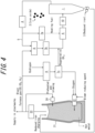
- FIG. 4 selectively illustrates the components used in Embodiment 4 from the components illustrated in FIG. 1 .
- the steelmaking line illustrated in FIG. 1 is used in Embodiment 4.
- reduced iron is produced according to the following procedure: First, the iron oxide 2 is charged into the reducing furnace 1 which is central to the reduced iron production process from the upper part, and the iron oxide 2 is gradually lowered. While lowering the iron oxide 2, high-temperature reducing gas containing CO, H 2 , and hydrocarbon is blown from the reducing gas blower 10 into the reducing furnace 1 at the intermediate part to reduce the iron oxide 2, and the reduced iron 3 is discharged from the lower part of the reducing furnace 1. In this reduction process in the reducing furnace 1, furnace top gas mainly containing CO, CO 2 , H 2 , and H 2 O is discharged from the upper part of the reducing furnace 1. The furnace top gas is subjected to dust removal in the dust remover 4.
- part of the furnace top gas is subjected to carbon dioxide separation in the carbon dioxide separator 8, and then moisture controlled in the second dehydrator 7b and fed into the heat-reformer 6 as raw material gas.
- the remaining furnace top gas is dehydrated in the first dehydrator 7a, and then used as heating fuel in the combustion chamber in the heat-reformer 6.
- the raw material gas not only the furnace top gas discharged from the reducing furnace 1 but also the blast furnace gas discharged from the blast furnace 21 can be used.
- the furnace top gas supplied into the heat-reformer 6 is then heated in the heat-reformer 6 together with the synthesized regenerative methane to generate high-temperature reducing gas.
- the furnace top gas and the blast furnace gas used as the raw material gas are moisture controlled to appropriately adjust the composition of the reducing gas.
- the furnace top gas and the blast furnace gas may also be subjected to CO 2 separation in the carbon dioxide separator 8.
- the regenerative methane, the furnace top gas, and the blast furnace gas are used as the raw material gas of the reducing gas, water or water vapor may be added for composition adjustment.
- a mechanism for promoting reaction, such as a catalyst, may be provided in the heat-reformer 6 to cause reforming reaction and generate reformed gas mainly containing CO and H 2 . Alternatively, only heating may be performed in the heat-reformer and the heated gas may be directly blown into the reducing furnace.
- the blast furnace operation in Embodiment 4 is the same as that in Embodiment 3.
- At least part of the blast furnace gas is introduced into the methane synthesizer 9.
- carbon monoxide and carbon dioxide contained in the blast furnace gas are reacted with hydrogen gas to generate regenerative methane gas.
- the regenerative methane gas is supplied into the heat-reformer 6 together with the raw material gas, to generate the reducing gas in the heat-reformer 6.
- the remaining regenerative methane gas may be blown into the blast furnace from the tuyere as a reducing agent.
- a carbon dioxide gas separation and recovery device for separating and recovering carbon dioxide gas from the blast furnace gas and a path for supplying the carbon dioxide gas recovered by the carbon dioxide gas separation and recovery device to the methane synthesizer 9 may be provided upstream of the methane synthesizer 9.
- residual gas in the carbon dioxide gas separation and recovery device containing fuel components such as carbon monoxide and hydrogen can be extracted and used as fuel in other processes in the steelworks, such as a coke oven or a power generator.
- our techniques can be implemented while supplying energy within the steelworks.
- the following reducing furnace operation was performed using the reduced iron production line schematically illustrated in FIG. 2 .
- 1394 kg/t of sintered ore was charged into the reducing furnace 1 from the upper part as the iron oxide 2, and 2200 Nm 3 /t of high-temperature reducing gas (H 2 : 62 vol%, CO: 38 vol%) heated to 800 °C was blown into the furnace 1 from the intermediate part.
- 2200 Nm 3 /t of furnace top gas H 2 : 46 vol%, CO: 29 vol%, CO 2 : 10 vol%, H 2 O: 15 vol%) was discharged from the upper part of the furnace 1.
- the furnace top gas was subjected to dust removal, and then 1501 Nm 3 /t of the furnace top gas was used as raw material gas and the remaining 699 Nm 3 /t furnace top gas was used as heating fuel gas in the heat-reformer 6.
- the furnace top gas as the raw material gas was moisture controlled to remove 86 kg/t of water, and then introduced into the heat-reformer 6.
- the furnace top gas as the heating fuel gas was dehydrated, and then combusted in the combustion chamber in the heat-reformer 6 using pure oxygen generated by a cryogenic separation process driven with CO 2 -free power.
- the whole amount of exhaust gas from the combustion chamber in the heat-reformer 6 was recovered and dehydrated, and 269 Nm 3 /t of the resultant combustion exhaust gas (CO 2 : 100 vol%) was fed into the methane synthesizer 9. 1075 Nm 3 /t of hydrogen generated by electrolysis using CO 2 -free power was also added into the methane synthesizer 9, to synthesize 269 Nm 3 /t of regenerative methane gas.
- the synthesized regenerative methane gas was fed into the heat-reformer 6 together with the furnace top gas as the raw material gas, and used as raw material of reducing gas.
- the following reducing furnace operation was performed using the reduced iron production line schematically illustrated in FIG. 3 .
- the conditions of sintered ore charged into the reducing furnace 1 reducing gas blown into the reducing furnace 1, furnace top gas discharged from the furnace top, and raw material gas were the same as those in Example 1.
- the remaining 699 Nm 3 /t furnace top gas other than the raw material gas was dehydrated and then fed into the methane synthesizer 9 as raw material for methane synthesis.
- 551 Nm 3 /t of hydrogen generated by electrolysis using CO 2 -free power was also added into the methane synthesizer 9, to synthesize 269 Nm 3 /t of regenerative methane gas.
- the synthesized regenerative methane gas was fed into the heat-reformer 6 and used as raw material of reducing gas. Instead of the heating fuel supplied to the heat-reformer 6 in Example 1, CO 2 -free power was supplied from outside, and electric heating was performed.
- Example 3 The reduced iron production process in Example 3 was similar to the reduced iron production process in Example 2, but not only furnace top gas but also blast furnace gas was used in the methane synthesizer 9.
- pure oxygen was used as blast gas to produce nitrogen-free blast furnace gas.
- 242 Nm 3 /t of the blast furnace gas (H 2 : 24 vol%, CO: 33 vol%, CO 2 : 43 vol%) generated under this condition was fed into the methane synthesizer 9 for methane synthesis together with 220 Nm 3 /t of the furnace top gas and 772 Nm 3 /t of hydrogen generated by electrolysis using CO 2 -free power.
- regenerative methane gas was generated in the methane synthesizer 9.
- the regenerative methane gas was fed into the heat-reformer 6 together with the furnace top gas as the raw material gas, and used as raw material of reducing gas.
- Part of the regenerative methane gas was fed into the blower 22 in the blast furnace 21 as a blown reducing agent.
- Part of the furnace top gas of the reducing furnace was combusted as fuel in the combustion chamber in the heat-reformer 6, but the resultant exhaust gas was not recovered.
- CO 2 -free power was supplied from outside (not illustrated), and electric heating was performed.
- the hydrogen gas charged into the methane synthesizer 9 for methane synthesis was generated by CO 2 -free power, so that no CO 2 was generated in the hydrogen production.
- the combustion exhaust gas of the heat-reformer 6 was discharged to outside the system, and consequently 362 kg/t of CO 2 was generated.
- CO 2 from the blast furnace 21 was reduced by 362 kg/t.
- the steelworks can be operated without a CO 2 increase by providing CO 2 -free power to compensate for lack of power due to insufficient blast furnace gas supply in the steelworks.
- a typical reducing furnace operation using a reduced iron production line illustrated in FIG. 5 was performed.
- the typical reducing furnace operation is Comparative Example 1 in which the raw material added to the furnace top gas as the raw material gas in Example 1 was not regenerative methane gas but natural gas.
- 2200 Nm 3 /t of high-temperature reducing gas (H 2 : 62 vol%, CO: 38 vol%) heated to 800 °C was blown into the reducing furnace 1 from the intermediate part, and reducing furnace operation was performed. Then, 2200 Nm 3 /t of furnace top gas (H 2 : 46 vol%, CO: 29 vol%, CO 2 : 10 vol%, H 2 O: 15 vol%) was discharged from the upper part of the furnace.
- the furnace top gas was subjected to dust removal, and then 1501 Nm 3 /t of the furnace top gas was used as raw material gas and the remaining 699 Nm 3 /t furnace top gas was used as heating fuel gas in the heat-reformer 6.
- the raw material gas was moisture controlled to remove 86 kg/t of water, and then fed into the heat-reformer 6.
- the heating fuel gas was dehydrated and then combusted in air in the combustion chamber in the heat-reformer 6, and the resultant combustion exhaust gas was diffused into the atmosphere. 269 Nm 3 /t of natural gas was fed into the heat-reformer 6 together with the foregoing process gas, to produce reducing gas.
- a typical reducing furnace operation using a reduced iron production line illustrated in FIG. 6 was performed.
- the typical reducing furnace operation is Comparative Example 2 in which the raw material added to the furnace top gas as the raw material gas in Example 1 was not regenerative methane gas but coke oven gas.
- Comparative Example 2 524 Nm 3 /t of coke oven gas was fed into the heat-reformer 6 to produce reduced iron, instead of natural gas in Comparative Example 1.
- CO 2 emitted as the combustion exhaust gas of the heat-reformer 6 was converted to 456 kg-CO 2 /t, as in Comparative Example 1.
- the coke oven gas used in Comparative Example 2 is important process gas used as fuel in downstream processes, such as burner fuel in a heating furnace, in integrated steelworks. If such coke oven gas is used in the reduced iron process in a large amount, lack of fuel occurs in the downstream processes.
- Coke oven gas generated when producing coke in a steelworks including a blast furnace of 10000 t/day is 1690000 Nm 3 /day.
- coke oven gas consumed in our reduced iron production process is 1570000 Nm 3 /t. This means almost the whole amount of coke oven gas generated is used in our reduced iron production process. It is therefore impossible to apply the method of Comparative Example 2 to actual steelworks.
Landscapes
- Engineering & Computer Science (AREA)
- Chemical & Material Sciences (AREA)
- Manufacturing & Machinery (AREA)
- Materials Engineering (AREA)
- Metallurgy (AREA)
- Organic Chemistry (AREA)
- Environmental & Geological Engineering (AREA)
- Mechanical Engineering (AREA)
- General Engineering & Computer Science (AREA)
- Manufacture Of Iron (AREA)
- Waste-Gas Treatment And Other Accessory Devices For Furnaces (AREA)
- Blast Furnaces (AREA)
- Industrial Gases (AREA)
Claims (11)
- Stahlherstellungsanlage, umfassend:einen Hochofen (21), der so konfiguriert ist, dass er Eisenoxid reduziert,einen Reduktionsofen (1), der so konfiguriert ist, dass er Eisenoxid (2) reduziert,einen Methansynthetisierer (9), der so konfiguriert ist, dass er Methan aus Hochofengas und/oder Ofengichtgas und Wasserstoffgas synthetisiert, wobei das Hochofengas von dem Hochofen (21) als Nebenprodukt erzeugt wird und Kohlendioxid, Kohlenmonoxid und Wasserstoff enthält, und das Ofengichtgas aus einer Ofengicht des Reduktionsofens (1) abgeführt wird und Kohlendioxid, Kohlenmonoxid und Wasserstoff enthält,ein Gebläse (22), das so konfiguriert ist, dass es Methangas, das durch den Methansynthetisierer (9) erzeugt wird, in den Hochofen (21) bläst,einen Wärme-Reformer (6), der so konfiguriert ist, dass er das Hochofengas und/oder das Ofengichtgas und das Methangas, das durch den Methansynthetisierer (9) synthetisiert wird, erwärmt oder wärmereformiert, um Reduktionsgas zu erzeugen, das Kohlenmonoxidgas und Wasserstoffgas enthält,ein Reduktionsgasgebläse (10), das so konfiguriert ist, dass es das Reduktionsgas in den Reduktionsofen (1) bläst, undeinen Zuführweg (5), der so konfiguriert ist, dass er das Ofengichtgas dem Methansynthetisierer (9) und/oder dem Wärme-Reformer (6) zuführt.
- Stahlherstellungsanlage gemäß Anspruch 1, umfassend
einen Kohlendioxidseparator (8), der so konfiguriert ist, dass er Kohlendioxid von dem Ofengichtgas abtrennt, im Zuführweg (5). - Stahlherstellungsanlage gemäß Anspruch 1 oder 2, umfassend:eine Kohlendioxidgastrennungs- und -rückgewinnungsvorrichtung, die so konfiguriert ist, dass sie Kohlendioxidgas von dem Hochofengas abtrennt und rückgewinnt, auf einer Stromabwärtsseite des Methansynthetisierers (9) undeinen Weg, der so konfiguriert ist, dass er das durch die Kohlendioxidgastrennungs- und -rückgewinnungsvorrichtung rückgewonnene Kohlendioxidgas dem Methansynthetisierer (9) zuführt.
- Verfahren zur Herstellung von reduziertem Eisen unter Verwendung der Stahlherstellungsanlage gemäß einem der Ansprüche 1 bis 3, wobei das Verfahren umfasst:Beschicken des Reduktionsofens (1) mit Eisenoxid (2),Einblasen von Reduktionsgas in den Reduktionsofen (1),Synthetisieren von Methan aus Mischgas oder Kohlendioxidgas und Wasserstoffgas, wobei das Mischgas Kohlendioxid und Kohlenmonoxid enthält,Erwärmen von Rohmaterialgas, das das Methangas und das Mischgas einschließt, und Reformieren des Rohmaterialgases zu Reduktionsgas undReduzieren des Eisenoxids (2) durch das Reduktionsgas im Reduktionsofen (1).
- Verfahren zur Herstellung von reduziertem Eisen gemäß Anspruch 4, wobei das Mischgas Hochofengas, das von dem Hochofen (21) als ein Nebenprodukt erzeugt wird, und/oder Ofengichtgas, das aus der Ofengicht des Reduktionsofens (1) abgeführt wird, ist.
- Verfahren zur Herstellung von reduziertem Eisen gemäß Anspruch 5, wobei ein Teil des Methangases, das beim Synthetisieren synthetisiert wird, in den Hochofen (21) geblasen wird.
- Verfahren zur Herstellung von reduziertem Eisen gemäß Anspruch 5 oder 6, wobei Sauerstoffgas zum Blasen im Hochofen (21) verwendet wird.
- Verfahren zur Herstellung von reduziertem Eisen unter Verwendung der Stahlherstellungsanlage gemäß einem der Ansprüche 1 bis 3, wobei das Verfahren umfasst:Beschicken des Reduktionsofens (1) mit Eisenoxid (2),Einblasen von Reduktionsgas in den Reduktionsofen (1),Abtrennen von Kohlendioxid von dem Ofengichtgas, das aus der Ofengicht des Reduktionsofens (1) abgeführt wird und Kohlendioxid, Kohlenmonoxid und Wasserstoff enthält, und Rückgewinnen von Mischgas, das Kohlenmonoxid und Wasserstoff enthält,Erwärmen von Rohmaterialgas, das das Mischgas einschließt, zur Erzeugung von Reduktionsgas undReduzieren des Eisenoxids (2) durch das Reduktionsgas im Reduktionsofen (1).
- Verfahren zur Herstellung von reduziertem Eisen gemäß Anspruch 8, wobei Methangas als Teil des Rohmaterialgases verwendet wird.
- Verfahren zur Herstellung von reduziertem Eisen gemäß Anspruch 9, wobei das Methangas regeneratives Methangas ist, das durch Synthetisieren von Methan aus einem Teil des Ofengichtgases und/oder einem Teil des Hochofengases und Wasserstoffgas erhalten wird, wobei das Ofengichtgas aus der Ofengicht des Reduktionsofens (1) abgeführt wird und Kohlendioxid, Kohlenmonoxid und Wasserstoff enthält, und das Hochofengas von dem Hochofen (21) als ein Nebenprodukt erzeugt wird und Kohlendioxid, Kohlenmonoxid und Wasserstoff enthält, und
ein Teil des regenerativen Methangases in den Hochofen (21) eingeblasen wird. - Verfahren zur Herstellung von reduziertem Eisen gemäß Anspruch 10, wobei Sauerstoffgas zum Blasen im Hochofen (21) verwendet wird.
Applications Claiming Priority (2)
| Application Number | Priority Date | Filing Date | Title |
|---|---|---|---|
| JP2020078526 | 2020-04-27 | ||
| PCT/JP2021/000237 WO2021220555A1 (ja) | 2020-04-27 | 2021-01-06 | 製鉄設備および還元鉄の製造方法 |
Publications (3)
| Publication Number | Publication Date |
|---|---|
| EP4144868A1 EP4144868A1 (de) | 2023-03-08 |
| EP4144868A4 EP4144868A4 (de) | 2023-08-30 |
| EP4144868B1 true EP4144868B1 (de) | 2024-07-24 |
Family
ID=78331932
Family Applications (1)
| Application Number | Title | Priority Date | Filing Date |
|---|---|---|---|
| EP21797227.2A Active EP4144868B1 (de) | 2020-04-27 | 2021-01-06 | Stahlherstellungslinie und verfahren zur herstellung von reduziertem eisen |
Country Status (7)
| Country | Link |
|---|---|
| US (1) | US12534770B2 (de) |
| EP (1) | EP4144868B1 (de) |
| JP (1) | JP7028373B1 (de) |
| KR (1) | KR102917028B1 (de) |
| CN (1) | CN115427588B (de) |
| TW (1) | TWI765521B (de) |
| WO (1) | WO2021220555A1 (de) |
Families Citing this family (13)
| Publication number | Priority date | Publication date | Assignee | Title |
|---|---|---|---|---|
| WO2022180425A1 (en) * | 2021-02-26 | 2022-09-01 | Arcelormittal | Method of manufacturing steel |
| WO2022180426A1 (en) * | 2021-02-26 | 2022-09-01 | Arcelormittal | A method of manufacturing of a steel product units |
| EP4219772A1 (de) * | 2022-01-28 | 2023-08-02 | Linde GmbH | Eisendirektreduktion mit reduzierter kohlendioxidfreisetzung |
| CN114480754A (zh) * | 2022-01-28 | 2022-05-13 | 新疆八一钢铁股份有限公司 | 一种碳氢耦合的高炉炼铁方法 |
| CN114634831A (zh) * | 2022-03-25 | 2022-06-17 | 新疆八一钢铁股份有限公司 | 一种高炉喷吹等离子矩重整循环冶金煤气的工艺方法 |
| CN119487216A (zh) | 2022-08-30 | 2025-02-18 | 杰富意矿物合金株式会社 | 循环型还原系统、铁矿石的还原方法以及熔矿炉的操作方法 |
| EP4596721A4 (de) * | 2022-12-23 | 2025-08-06 | Jfe Steel Corp | Herstellungsverfahren für reduziertes eisen |
| EP4662337A1 (de) * | 2023-02-07 | 2025-12-17 | KT Tech S.p.A. | Verfahren zur direktreduktion von eisenerzen mittels eines mittels katalytischer teiloxidation erzeugten synthesegases |
| TWI906913B (zh) * | 2023-06-21 | 2025-12-01 | 日商日本製鐵股份有限公司 | 高爐的作業方法 |
| DE102023128085A1 (de) * | 2023-10-13 | 2025-04-17 | Sms Group Gmbh | Wassergewinnung unter Verwendung einer Direktreduktionsanlage |
| KR102927135B1 (ko) * | 2023-11-29 | 2026-02-11 | 현대제철 주식회사 | 수소 및 일산화탄소 생산 및 활용 시스템 및 방법 |
| TWI860214B (zh) * | 2023-12-20 | 2024-10-21 | 中國鋼鐵股份有限公司 | 監控方法、監控系統及非暫態電腦可讀取媒體 |
| WO2026048419A1 (ja) * | 2024-08-27 | 2026-03-05 | Jfeスチール株式会社 | 還元鉄の製造方法および還元鉄の製造システム |
Family Cites Families (26)
| Publication number | Priority date | Publication date | Assignee | Title |
|---|---|---|---|---|
| SU1609456A3 (ru) | 1985-07-18 | 1990-11-23 | Кабусики Кайся Кобе Сейкосе (Фирма) | Способ пр мого получени железа |
| AT385051B (de) * | 1986-08-07 | 1988-02-10 | Voest Alpine Ag | Huettenwerk und verfahren zur erzeugung von stahl |
| US6045602A (en) * | 1998-10-28 | 2000-04-04 | Praxair Technology, Inc. | Method for integrating a blast furnace and a direct reduction reactor using cryogenic rectification |
| AT409634B (de) | 2000-05-15 | 2002-09-25 | Voest Alpine Ind Anlagen | Verfahren und vorrichtung zur herstellung von roheisen oder flüssigen stahlvorprodukten aus eisenerzhältigen einsatzstoffen |
| MY133537A (en) | 2002-01-24 | 2007-11-30 | Kobe Steel Ltd | Method for making molten iron |
| EP1641945B1 (de) * | 2003-05-15 | 2018-12-12 | HYLSA, S.A. de C.V. | Verfahren und vorrichtung zur verbesserten verwendung von primärenergiequellen in integrierten stahlwerken |
| CN100523228C (zh) | 2007-07-31 | 2009-08-05 | 张文慧 | 利用焦炉气制还原气生产海绵铁的方法及其设备 |
| AT508522B1 (de) | 2009-07-31 | 2011-04-15 | Siemens Vai Metals Tech Gmbh | Reformergasbasiertes reduktionsverfahren mit vermindertem nox-ausstoss |
| WO2011012964A2 (en) | 2009-07-31 | 2011-02-03 | Hyl Technologies, S.A. De C.V. | Method for producing direct reduced iron with limited co2 emissions |
| WO2011108546A1 (ja) * | 2010-03-02 | 2011-09-09 | Jfeスチール株式会社 | 高炉の操業方法、製鉄所の操業方法、および酸化炭素含有ガスの利用方法 |
| JP5640803B2 (ja) * | 2010-03-29 | 2014-12-17 | Jfeスチール株式会社 | 高炉又は製鉄所の操業方法 |
| JP2012007213A (ja) | 2010-06-25 | 2012-01-12 | Mitsubishi Heavy Ind Ltd | 直接還元製鉄法およびそのための還元ガス製造装置 |
| AT511892B1 (de) * | 2011-08-31 | 2013-07-15 | Siemens Vai Metals Tech Gmbh | Verfahren zur aufbereitung von abgasen aus anlagen zur roheisenherstellung und/oder von synthesegas |
| KR101321072B1 (ko) | 2011-09-06 | 2013-10-23 | 주식회사 포스코 | 일산화탄소 및 수소를 포함하는 합성가스 제조장치 및 그의 제조방법 |
| MX2014007865A (es) | 2011-12-27 | 2015-03-27 | Hyl Technologies Sa De Cv | Alto horno con recirculacion de gas efluente. |
| CN102758048A (zh) | 2012-07-30 | 2012-10-31 | 中冶南方工程技术有限公司 | 原燃料热装、全热氧高炉与竖炉联合生产工艺 |
| JP6019893B2 (ja) * | 2012-07-31 | 2016-11-02 | Jfeスチール株式会社 | 高炉の操業方法 |
| WO2014040989A2 (de) | 2012-09-14 | 2014-03-20 | Voestalpine Stahl Gmbh | Verfahren zum erzeugen von stahl |
| AR094927A1 (es) * | 2013-02-27 | 2015-09-09 | Hyl Tech S A De C V | Proceso de reducción directa con aumento de la calidad del producto y la eficacia del gas del proceso |
| DE102013009993A1 (de) | 2013-06-14 | 2014-12-18 | CCP Technology GmbH | Hochofen und Verfahren zum Betrieb eines Hochofens |
| JP6611013B2 (ja) | 2013-07-09 | 2019-11-27 | ミツビシ ヒタチ パワー システムズ ヨーロッパ ゲーエムベーハー | 柔軟に運転可能な電力プラントおよびそれの運転のための方法 |
| UA117374C2 (uk) | 2013-07-31 | 2018-07-25 | Мідрекс Текнолоджиз, Інк. | Відновлення оксиду заліза до металевого заліза із застосуванням коксового газу та газу зі сталеплавильної печі з подачею кисню |
| CN106103746B (zh) * | 2014-03-26 | 2018-07-31 | 杰富意钢铁株式会社 | 氧气高炉的操作方法 |
| US10316376B2 (en) | 2015-06-24 | 2019-06-11 | Midrex Technologies, Inc. | Methods and systems for increasing the carbon content of sponge iron in a reduction furnace |
| JP2017088912A (ja) | 2015-11-04 | 2017-05-25 | 株式会社神戸製鋼所 | 還元鉄の製造方法 |
| US20190323098A1 (en) | 2016-12-22 | 2019-10-24 | Sabic Global Technologies B.V. | Direct reduction process for the production of direct-reduced iron with high purity methane |
-
2021
- 2021-01-06 WO PCT/JP2021/000237 patent/WO2021220555A1/ja not_active Ceased
- 2021-01-06 JP JP2021540264A patent/JP7028373B1/ja active Active
- 2021-01-06 EP EP21797227.2A patent/EP4144868B1/de active Active
- 2021-01-06 KR KR1020227039871A patent/KR102917028B1/ko active Active
- 2021-01-06 US US17/995,310 patent/US12534770B2/en active Active
- 2021-01-06 CN CN202180029381.4A patent/CN115427588B/zh active Active
- 2021-01-11 TW TW110100903A patent/TWI765521B/zh active
Also Published As
| Publication number | Publication date |
|---|---|
| JPWO2021220555A1 (de) | 2021-11-04 |
| KR102917028B1 (ko) | 2026-01-22 |
| US20230175084A1 (en) | 2023-06-08 |
| TWI765521B (zh) | 2022-05-21 |
| US12534770B2 (en) | 2026-01-27 |
| TW202140804A (zh) | 2021-11-01 |
| CN115427588B (zh) | 2024-08-06 |
| EP4144868A1 (de) | 2023-03-08 |
| BR112022021678A2 (pt) | 2022-12-20 |
| CN115427588A (zh) | 2022-12-02 |
| EP4144868A4 (de) | 2023-08-30 |
| KR20220162174A (ko) | 2022-12-07 |
| JP7028373B1 (ja) | 2022-03-02 |
| CA3179019A1 (en) | 2021-11-04 |
| WO2021220555A1 (ja) | 2021-11-04 |
Similar Documents
| Publication | Publication Date | Title |
|---|---|---|
| US12534770B2 (en) | Steelmaking line and method of producing reduced iron | |
| AU2022294517B2 (en) | Method of producing reduced iron | |
| JP7028364B2 (ja) | 高炉の操業方法および高炉附帯設備 | |
| US12365953B2 (en) | Method of operating blast furnace and blast furnace ancillary facility | |
| EP4141130A1 (de) | Hochofenbetriebsverfahren und hilfsanlage für hochofen | |
| US20220380860A1 (en) | Method of operating blast furnace and blast furnace ancillary facility | |
| JP7605376B2 (ja) | 還元鉄の製造方法 | |
| CA3179019C (en) | Steelmaking line and method of producing reduced iron | |
| RU2808735C1 (ru) | Линия производства восстановленного железа и способ получения восстановленного железа | |
| CN120513306A (zh) | 还原铁的制造方法 | |
| JP7272312B2 (ja) | 還元鉄の製造方法 | |
| JP7736187B2 (ja) | 還元鉄の製造方法 | |
| JP2021175821A (ja) | 高炉の操業方法および高炉附帯設備 | |
| JP7740549B2 (ja) | 還元鉄の製造方法 | |
| BR112022021678B1 (pt) | Linha de fabricação de aço e método de produção de ferro reduzido | |
| EP4095268A1 (de) | Hochofenbetriebsverfahren und hilfsgerät eines hochofens | |
| EP4089185A1 (de) | Hochofenbetriebsverfahren und hochofennebenanlage | |
| JP2026052010A (ja) | 高炉ガスの調整方法、水素の回収方法及び二酸化炭素の気体源の回収方法 | |
| WO2025187290A1 (ja) | 高炉の操業方法および高炉附帯設備 |
Legal Events
| Date | Code | Title | Description |
|---|---|---|---|
| STAA | Information on the status of an ep patent application or granted ep patent |
Free format text: STATUS: THE INTERNATIONAL PUBLICATION HAS BEEN MADE |
|
| PUAI | Public reference made under article 153(3) epc to a published international application that has entered the european phase |
Free format text: ORIGINAL CODE: 0009012 |
|
| STAA | Information on the status of an ep patent application or granted ep patent |
Free format text: STATUS: REQUEST FOR EXAMINATION WAS MADE |
|
| 17P | Request for examination filed |
Effective date: 20221019 |
|
| AK | Designated contracting states |
Kind code of ref document: A1 Designated state(s): AL AT BE BG CH CY CZ DE DK EE ES FI FR GB GR HR HU IE IS IT LI LT LU LV MC MK MT NL NO PL PT RO RS SE SI SK SM TR |
|
| DAV | Request for validation of the european patent (deleted) | ||
| DAX | Request for extension of the european patent (deleted) | ||
| A4 | Supplementary search report drawn up and despatched |
Effective date: 20230726 |
|
| RIC1 | Information provided on ipc code assigned before grant |
Ipc: F27D 17/00 20060101ALI20230721BHEP Ipc: C21B 13/00 20060101ALI20230721BHEP Ipc: C21B 7/00 20060101ALI20230721BHEP Ipc: C21B 5/06 20060101ALI20230721BHEP Ipc: C21B 5/00 20060101AFI20230721BHEP |
|
| GRAP | Despatch of communication of intention to grant a patent |
Free format text: ORIGINAL CODE: EPIDOSNIGR1 |
|
| STAA | Information on the status of an ep patent application or granted ep patent |
Free format text: STATUS: GRANT OF PATENT IS INTENDED |
|
| INTG | Intention to grant announced |
Effective date: 20240312 |
|
| GRAS | Grant fee paid |
Free format text: ORIGINAL CODE: EPIDOSNIGR3 |
|
| GRAA | (expected) grant |
Free format text: ORIGINAL CODE: 0009210 |
|
| STAA | Information on the status of an ep patent application or granted ep patent |
Free format text: STATUS: THE PATENT HAS BEEN GRANTED |
|
| AK | Designated contracting states |
Kind code of ref document: B1 Designated state(s): AL AT BE BG CH CY CZ DE DK EE ES FI FR GB GR HR HU IE IS IT LI LT LU LV MC MK MT NL NO PL PT RO RS SE SI SK SM TR |
|
| REG | Reference to a national code |
Ref country code: GB Ref legal event code: FG4D |
|
| REG | Reference to a national code |
Ref country code: CH Ref legal event code: EP |
|
| REG | Reference to a national code |
Ref country code: IE Ref legal event code: FG4D Ref country code: DE Ref legal event code: R096 Ref document number: 602021016244 Country of ref document: DE |
|
| REG | Reference to a national code |
Ref country code: LT Ref legal event code: MG9D |
|
| REG | Reference to a national code |
Ref country code: NL Ref legal event code: MP Effective date: 20240724 |
|
| PG25 | Lapsed in a contracting state [announced via postgrant information from national office to epo] |
Ref country code: PT Free format text: LAPSE BECAUSE OF FAILURE TO SUBMIT A TRANSLATION OF THE DESCRIPTION OR TO PAY THE FEE WITHIN THE PRESCRIBED TIME-LIMIT Effective date: 20241125 |
|
| REG | Reference to a national code |
Ref country code: AT Ref legal event code: MK05 Ref document number: 1706376 Country of ref document: AT Kind code of ref document: T Effective date: 20240724 |
|
| PG25 | Lapsed in a contracting state [announced via postgrant information from national office to epo] |
Ref country code: NL Free format text: LAPSE BECAUSE OF FAILURE TO SUBMIT A TRANSLATION OF THE DESCRIPTION OR TO PAY THE FEE WITHIN THE PRESCRIBED TIME-LIMIT Effective date: 20240724 |
|
| PG25 | Lapsed in a contracting state [announced via postgrant information from national office to epo] |
Ref country code: PT Free format text: LAPSE BECAUSE OF FAILURE TO SUBMIT A TRANSLATION OF THE DESCRIPTION OR TO PAY THE FEE WITHIN THE PRESCRIBED TIME-LIMIT Effective date: 20241125 Ref country code: NL Free format text: LAPSE BECAUSE OF FAILURE TO SUBMIT A TRANSLATION OF THE DESCRIPTION OR TO PAY THE FEE WITHIN THE PRESCRIBED TIME-LIMIT Effective date: 20240724 |
|
| PG25 | Lapsed in a contracting state [announced via postgrant information from national office to epo] |
Ref country code: NO Free format text: LAPSE BECAUSE OF FAILURE TO SUBMIT A TRANSLATION OF THE DESCRIPTION OR TO PAY THE FEE WITHIN THE PRESCRIBED TIME-LIMIT Effective date: 20241024 |
|
| PG25 | Lapsed in a contracting state [announced via postgrant information from national office to epo] |
Ref country code: PL Free format text: LAPSE BECAUSE OF FAILURE TO SUBMIT A TRANSLATION OF THE DESCRIPTION OR TO PAY THE FEE WITHIN THE PRESCRIBED TIME-LIMIT Effective date: 20240724 Ref country code: FI Free format text: LAPSE BECAUSE OF FAILURE TO SUBMIT A TRANSLATION OF THE DESCRIPTION OR TO PAY THE FEE WITHIN THE PRESCRIBED TIME-LIMIT Effective date: 20240724 Ref country code: GR Free format text: LAPSE BECAUSE OF FAILURE TO SUBMIT A TRANSLATION OF THE DESCRIPTION OR TO PAY THE FEE WITHIN THE PRESCRIBED TIME-LIMIT Effective date: 20241025 |
|
| PG25 | Lapsed in a contracting state [announced via postgrant information from national office to epo] |
Ref country code: BG Free format text: LAPSE BECAUSE OF FAILURE TO SUBMIT A TRANSLATION OF THE DESCRIPTION OR TO PAY THE FEE WITHIN THE PRESCRIBED TIME-LIMIT Effective date: 20240724 |
|
| PG25 | Lapsed in a contracting state [announced via postgrant information from national office to epo] |
Ref country code: LV Free format text: LAPSE BECAUSE OF FAILURE TO SUBMIT A TRANSLATION OF THE DESCRIPTION OR TO PAY THE FEE WITHIN THE PRESCRIBED TIME-LIMIT Effective date: 20240724 |
|
| PG25 | Lapsed in a contracting state [announced via postgrant information from national office to epo] |
Ref country code: IS Free format text: LAPSE BECAUSE OF FAILURE TO SUBMIT A TRANSLATION OF THE DESCRIPTION OR TO PAY THE FEE WITHIN THE PRESCRIBED TIME-LIMIT Effective date: 20241124 Ref country code: AT Free format text: LAPSE BECAUSE OF FAILURE TO SUBMIT A TRANSLATION OF THE DESCRIPTION OR TO PAY THE FEE WITHIN THE PRESCRIBED TIME-LIMIT Effective date: 20240724 |
|
| PG25 | Lapsed in a contracting state [announced via postgrant information from national office to epo] |
Ref country code: HR Free format text: LAPSE BECAUSE OF FAILURE TO SUBMIT A TRANSLATION OF THE DESCRIPTION OR TO PAY THE FEE WITHIN THE PRESCRIBED TIME-LIMIT Effective date: 20240724 |
|
| PG25 | Lapsed in a contracting state [announced via postgrant information from national office to epo] |
Ref country code: ES Free format text: LAPSE BECAUSE OF FAILURE TO SUBMIT A TRANSLATION OF THE DESCRIPTION OR TO PAY THE FEE WITHIN THE PRESCRIBED TIME-LIMIT Effective date: 20240724 Ref country code: RS Free format text: LAPSE BECAUSE OF FAILURE TO SUBMIT A TRANSLATION OF THE DESCRIPTION OR TO PAY THE FEE WITHIN THE PRESCRIBED TIME-LIMIT Effective date: 20241024 |
|
| PG25 | Lapsed in a contracting state [announced via postgrant information from national office to epo] |
Ref country code: RS Free format text: LAPSE BECAUSE OF FAILURE TO SUBMIT A TRANSLATION OF THE DESCRIPTION OR TO PAY THE FEE WITHIN THE PRESCRIBED TIME-LIMIT Effective date: 20241024 Ref country code: PL Free format text: LAPSE BECAUSE OF FAILURE TO SUBMIT A TRANSLATION OF THE DESCRIPTION OR TO PAY THE FEE WITHIN THE PRESCRIBED TIME-LIMIT Effective date: 20240724 Ref country code: NO Free format text: LAPSE BECAUSE OF FAILURE TO SUBMIT A TRANSLATION OF THE DESCRIPTION OR TO PAY THE FEE WITHIN THE PRESCRIBED TIME-LIMIT Effective date: 20241024 Ref country code: LV Free format text: LAPSE BECAUSE OF FAILURE TO SUBMIT A TRANSLATION OF THE DESCRIPTION OR TO PAY THE FEE WITHIN THE PRESCRIBED TIME-LIMIT Effective date: 20240724 Ref country code: IS Free format text: LAPSE BECAUSE OF FAILURE TO SUBMIT A TRANSLATION OF THE DESCRIPTION OR TO PAY THE FEE WITHIN THE PRESCRIBED TIME-LIMIT Effective date: 20241124 Ref country code: HR Free format text: LAPSE BECAUSE OF FAILURE TO SUBMIT A TRANSLATION OF THE DESCRIPTION OR TO PAY THE FEE WITHIN THE PRESCRIBED TIME-LIMIT Effective date: 20240724 Ref country code: GR Free format text: LAPSE BECAUSE OF FAILURE TO SUBMIT A TRANSLATION OF THE DESCRIPTION OR TO PAY THE FEE WITHIN THE PRESCRIBED TIME-LIMIT Effective date: 20241025 Ref country code: FI Free format text: LAPSE BECAUSE OF FAILURE TO SUBMIT A TRANSLATION OF THE DESCRIPTION OR TO PAY THE FEE WITHIN THE PRESCRIBED TIME-LIMIT Effective date: 20240724 Ref country code: ES Free format text: LAPSE BECAUSE OF FAILURE TO SUBMIT A TRANSLATION OF THE DESCRIPTION OR TO PAY THE FEE WITHIN THE PRESCRIBED TIME-LIMIT Effective date: 20240724 Ref country code: BG Free format text: LAPSE BECAUSE OF FAILURE TO SUBMIT A TRANSLATION OF THE DESCRIPTION OR TO PAY THE FEE WITHIN THE PRESCRIBED TIME-LIMIT Effective date: 20240724 Ref country code: AT Free format text: LAPSE BECAUSE OF FAILURE TO SUBMIT A TRANSLATION OF THE DESCRIPTION OR TO PAY THE FEE WITHIN THE PRESCRIBED TIME-LIMIT Effective date: 20240724 |
|
| PG25 | Lapsed in a contracting state [announced via postgrant information from national office to epo] |
Ref country code: DK Free format text: LAPSE BECAUSE OF FAILURE TO SUBMIT A TRANSLATION OF THE DESCRIPTION OR TO PAY THE FEE WITHIN THE PRESCRIBED TIME-LIMIT Effective date: 20240724 Ref country code: SM Free format text: LAPSE BECAUSE OF FAILURE TO SUBMIT A TRANSLATION OF THE DESCRIPTION OR TO PAY THE FEE WITHIN THE PRESCRIBED TIME-LIMIT Effective date: 20240724 Ref country code: RO Free format text: LAPSE BECAUSE OF FAILURE TO SUBMIT A TRANSLATION OF THE DESCRIPTION OR TO PAY THE FEE WITHIN THE PRESCRIBED TIME-LIMIT Effective date: 20240724 |
|
| PG25 | Lapsed in a contracting state [announced via postgrant information from national office to epo] |
Ref country code: EE Free format text: LAPSE BECAUSE OF FAILURE TO SUBMIT A TRANSLATION OF THE DESCRIPTION OR TO PAY THE FEE WITHIN THE PRESCRIBED TIME-LIMIT Effective date: 20240724 |
|
| PG25 | Lapsed in a contracting state [announced via postgrant information from national office to epo] |
Ref country code: CZ Free format text: LAPSE BECAUSE OF FAILURE TO SUBMIT A TRANSLATION OF THE DESCRIPTION OR TO PAY THE FEE WITHIN THE PRESCRIBED TIME-LIMIT Effective date: 20240724 |
|
| REG | Reference to a national code |
Ref country code: DE Ref legal event code: R097 Ref document number: 602021016244 Country of ref document: DE |
|
| PG25 | Lapsed in a contracting state [announced via postgrant information from national office to epo] |
Ref country code: SK Free format text: LAPSE BECAUSE OF FAILURE TO SUBMIT A TRANSLATION OF THE DESCRIPTION OR TO PAY THE FEE WITHIN THE PRESCRIBED TIME-LIMIT Effective date: 20240724 Ref country code: IT Free format text: LAPSE BECAUSE OF FAILURE TO SUBMIT A TRANSLATION OF THE DESCRIPTION OR TO PAY THE FEE WITHIN THE PRESCRIBED TIME-LIMIT Effective date: 20240724 |
|
| PLBE | No opposition filed within time limit |
Free format text: ORIGINAL CODE: 0009261 |
|
| STAA | Information on the status of an ep patent application or granted ep patent |
Free format text: STATUS: NO OPPOSITION FILED WITHIN TIME LIMIT |
|
| 26N | No opposition filed |
Effective date: 20250425 |
|
| REG | Reference to a national code |
Ref country code: CH Ref legal event code: PL |
|
| PG25 | Lapsed in a contracting state [announced via postgrant information from national office to epo] |
Ref country code: SE Free format text: LAPSE BECAUSE OF FAILURE TO SUBMIT A TRANSLATION OF THE DESCRIPTION OR TO PAY THE FEE WITHIN THE PRESCRIBED TIME-LIMIT Effective date: 20240724 |
|
| PG25 | Lapsed in a contracting state [announced via postgrant information from national office to epo] |
Ref country code: MC Free format text: LAPSE BECAUSE OF FAILURE TO SUBMIT A TRANSLATION OF THE DESCRIPTION OR TO PAY THE FEE WITHIN THE PRESCRIBED TIME-LIMIT Effective date: 20240724 Ref country code: LU Free format text: LAPSE BECAUSE OF NON-PAYMENT OF DUE FEES Effective date: 20250106 |
|
| GBPC | Gb: european patent ceased through non-payment of renewal fee |
Effective date: 20250106 |
|
| PG25 | Lapsed in a contracting state [announced via postgrant information from national office to epo] |
Ref country code: GB Free format text: LAPSE BECAUSE OF NON-PAYMENT OF DUE FEES Effective date: 20250106 Ref country code: BE Free format text: LAPSE BECAUSE OF NON-PAYMENT OF DUE FEES Effective date: 20250131 |
|
| PG25 | Lapsed in a contracting state [announced via postgrant information from national office to epo] |
Ref country code: CH Free format text: LAPSE BECAUSE OF NON-PAYMENT OF DUE FEES Effective date: 20250131 |
|
| REG | Reference to a national code |
Ref country code: BE Ref legal event code: MM Effective date: 20250131 |
|
| PGFP | Annual fee paid to national office [announced via postgrant information from national office to epo] |
Ref country code: FR Payment date: 20251128 Year of fee payment: 6 |
|
| PG25 | Lapsed in a contracting state [announced via postgrant information from national office to epo] |
Ref country code: IE Free format text: LAPSE BECAUSE OF NON-PAYMENT OF DUE FEES Effective date: 20250106 |
|
| PGFP | Annual fee paid to national office [announced via postgrant information from national office to epo] |
Ref country code: DE Payment date: 20251203 Year of fee payment: 6 |
|
| PGFP | Annual fee paid to national office [announced via postgrant information from national office to epo] |
Ref country code: TR Payment date: 20260105 Year of fee payment: 6 |