EP4144931B1 - Paneel-system zur thermischen isolierung einer beschatteten oberfläche - Google Patents
Paneel-system zur thermischen isolierung einer beschatteten oberfläche Download PDFInfo
- Publication number
- EP4144931B1 EP4144931B1 EP22169747.7A EP22169747A EP4144931B1 EP 4144931 B1 EP4144931 B1 EP 4144931B1 EP 22169747 A EP22169747 A EP 22169747A EP 4144931 B1 EP4144931 B1 EP 4144931B1
- Authority
- EP
- European Patent Office
- Prior art keywords
- lamellae
- panels
- supporting construction
- envelope
- panel
- Prior art date
- Legal status (The legal status is an assumption and is not a legal conclusion. Google has not performed a legal analysis and makes no representation as to the accuracy of the status listed.)
- Active
Links
Images


Classifications
-
- E—FIXED CONSTRUCTIONS
- E04—BUILDING
- E04F—FINISHING WORK ON BUILDINGS, e.g. STAIRS, FLOORS
- E04F10/00—Sunshades, e.g. Florentine blinds or jalousies; Outside screens; Awnings or baldachins
- E04F10/08—Sunshades, e.g. Florentine blinds or jalousies; Outside screens; Awnings or baldachins of a plurality of similar rigid parts, e.g. slabs, lamellae
-
- E—FIXED CONSTRUCTIONS
- E04—BUILDING
- E04F—FINISHING WORK ON BUILDINGS, e.g. STAIRS, FLOORS
- E04F10/00—Sunshades, e.g. Florentine blinds or jalousies; Outside screens; Awnings or baldachins
- E04F10/08—Sunshades, e.g. Florentine blinds or jalousies; Outside screens; Awnings or baldachins of a plurality of similar rigid parts, e.g. slabs, lamellae
- E04F10/10—Sunshades, e.g. Florentine blinds or jalousies; Outside screens; Awnings or baldachins of a plurality of similar rigid parts, e.g. slabs, lamellae collapsible or extensible; metallic Florentine blinds; awnings with movable parts such as louvres
-
- E—FIXED CONSTRUCTIONS
- E06—DOORS, WINDOWS, SHUTTERS, OR ROLLER BLINDS IN GENERAL; LADDERS
- E06B—FIXED OR MOVABLE CLOSURES FOR OPENINGS IN BUILDINGS, VEHICLES, FENCES OR LIKE ENCLOSURES IN GENERAL, e.g. DOORS, WINDOWS, BLINDS, GATES
- E06B9/00—Screening or protective devices for wall or similar openings, with or without operating or securing mechanisms; Closures of similar construction
- E06B9/24—Screens or other constructions affording protection against light, especially against sunshine; Similar screens for privacy or appearance; Slat blinds
- E06B9/26—Lamellar or like blinds, e.g. venetian blinds
- E06B9/28—Lamellar or like blinds, e.g. venetian blinds with horizontal lamellae, e.g. non-liftable
-
- E—FIXED CONSTRUCTIONS
- E06—DOORS, WINDOWS, SHUTTERS, OR ROLLER BLINDS IN GENERAL; LADDERS
- E06B—FIXED OR MOVABLE CLOSURES FOR OPENINGS IN BUILDINGS, VEHICLES, FENCES OR LIKE ENCLOSURES IN GENERAL, e.g. DOORS, WINDOWS, BLINDS, GATES
- E06B9/00—Screening or protective devices for wall or similar openings, with or without operating or securing mechanisms; Closures of similar construction
- E06B9/24—Screens or other constructions affording protection against light, especially against sunshine; Similar screens for privacy or appearance; Slat blinds
- E06B9/26—Lamellar or like blinds, e.g. venetian blinds
- E06B9/38—Other details
- E06B9/386—Details of lamellae
-
- E—FIXED CONSTRUCTIONS
- E06—DOORS, WINDOWS, SHUTTERS, OR ROLLER BLINDS IN GENERAL; LADDERS
- E06B—FIXED OR MOVABLE CLOSURES FOR OPENINGS IN BUILDINGS, VEHICLES, FENCES OR LIKE ENCLOSURES IN GENERAL, e.g. DOORS, WINDOWS, BLINDS, GATES
- E06B9/00—Screening or protective devices for wall or similar openings, with or without operating or securing mechanisms; Closures of similar construction
- E06B9/24—Screens or other constructions affording protection against light, especially against sunshine; Similar screens for privacy or appearance; Slat blinds
- E06B2009/2417—Light path control; means to control reflection
Definitions
- Sunlight is one of the essential resources for many activities, both professional and private. Its availability determines the arrangement of day and night zones in residential buildings or work and storage places in production buildings. In the case of large-scale buildings in the form of halls, lighting is often installed above the production lines in order to improve working conditions and safety. Sunlight is undoubtedly the healthiest in terms of colour and safe, for example in working environments with moving, especially rotating equipment. In addition, it costs nothing, which makes it desirable also from an economic point of view.
- Typical interior blinds consist of a set of lamellae attached to tilt wands or suspended on cords, their position or the degree of shading of glazing is regulated by shortening or lengthening the rods and cords.
- An example of this type of solution is the blind disclosed in description GR20180200111 , the lamellae of which are connected by a tilt wand allowing to change the angle of their inclination in relation to the pane from a perpendicular position to completely closing the way for light.
- interior blinds together with room darkening do not reduce the heating of the window itself, which becomes an additional heat radiator.
- roller blinds there are also known various types of roller blinds in which material of different transparency is mounted on a rotating shaft. Depending on the chosen thickness and transparency of the material, shading effect is achieved. Roller blind fabrics may be reinforced or even multi-layered in order to additionally stop room heating. This type of fabric and its manufacturing method is presented by CN208564410 .
- roller blind takes the form of plastic or metal armouring, sometimes with anti-intrusion characteristics.
- lamella systems intended for facade shading in which the position of the lamellae is fixed and they are fixed directly to the facade of a building or to the window frame, or in other variants they are fixed to a supporting construction mounted to the facade or to glazed building envelopes.
- Such constructions are characterised by a uniform in the top view shape of the individual lamellae and the fixed, constant and equal inclination angle for the individual lamellae in relation to the building envelope.
- the optimal solution for preventing the heating of the building envelope or the sheltered room while at the same time ensuring its optimal illumination is not to use blinds with a variable inclination angle or non-transparent materials, but to use a variable shape of lamellae with at least 30% light transmission and a fixed inclination angle in combination with ensuring ventilation of the space between the building envelope and the shading device.
- Document US 2 859 494 A discloses a panel-layer system for thermal insulation of a shaded surface, comprising a supporting construction in the form of two rigid and non-deformable rails, the supporting construction being adapted to be mounted to the outer side of a building envelope, a plurality of lamellae permanently mounted to the supporting construction, wherein the lamellae are inserted into notches of the supporting construction.
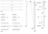
- the panel-layer system for thermal insulation of the shaded surface according to the invention is mountable to the outer side of the building envelope, especially a window, especially a roof window, and comprises a supporting construction in the form of at least two rigid and non-deformable rails, to which the lamellae are permanently mounted, preferably by a mounting batten, and the outer (in relation to the sheltered envelope) edge of the lamellae preferably has an irregular shape.
- the lamellae are inserted into notches made in the supporting construction and are additionally glued to it.
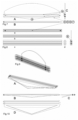
- the lamellae are made in such a way that they have a panel structure and are built of panels put together and inserted into a slot in the mounting batten.
- the ends of the mounting batten are fixed to at least two, rigid and non-deformable rails forming the supporting construction.
- the panels are preferably joined by shape, preferably snap-fit.
- the mounting batten in cross-section has preferably a basic C-shape with at least one additional longitudinal selection, for example at least with a one-sided groove.
- Each panel at least on one side has a longitudinal rib cooperating with at least one additional longitudinal selection, for example at least a one-sided groove.
- shape, colour as well as the degree of light transmission may be varied for each lamella and/or for each panel.
- shape, colour as well as the degree of light transmission may be varied for each lamella and/or for each panel.
- shape, colour as well as the degree of light transmission may be varied for each lamella and/or for each panel.
- the windows are vertically oriented and the inclination angle of the lamellae is maintained, in the upper part of the building envelope, the inclination angle is no more than 70° in relation to the envelope plane and decreases towards the bottom of the envelope so that the lowest lamella is inclined at an angle of no less than 45.
- the inclination angle of the lamellae is in the range of 45-70 degrees and the variation of the inclination angles of the lamellae is linear.
- the inclination angle of the lamellae varies linearly from the highest to the lowest lamella by the difference in the inclination of the highest and lowest lamella/number of lamellae and the distance between the lamellae measured along the edge of the supporting construction is the difference in the inclination angle of the outermost lamellae/number of lamellae.
- the supporting construction shall be mounted to the building envelope so that an air cavity of at least 10 mm and no more than 100 mm is maintained between this construction, the lamellae mounted on it and the plane of the building envelope.
- the supporting construction is mounted outside the window in such a way that at least two rigid and non-deformable rails are latched in cantilevers screwed into the upper part of the building envelope frame, especially the window, and are supported by two cantilevers that block the movement of the blinds laterally and in the vertical plane of the envelope, especially the window frame in its lower part.
- the supporting construction and the lamellae are made of plastic
- the supporting construction is made of Pet plastic and the lamellae are cut out from plexiglass.
- At least one surface of each lamella is covered with a sunlight-reflecting film having a transparency of at least 20%, but not more than 90% of the ability to retain light radiation.
- a sunlight-reflecting film having a transparency of at least 20%, but not more than 90% of the ability to retain light radiation.
- aluminium dust fixed on the surface of the lamellae.
- At least one surface of the lamellae is sprayed with a film having photochromatic properties which reacts to the intensity of a light wave by changing the degree of this wave transmittance.
- At least one surface of the lamellae is covered with a solar window film having a shading degree between 20 and 90%.
- the lamellae are covered with a photochromic film or foil having a shading capability from 20 to 90%.
- the outer edge of the lamellae has a shape selected from a sinusoid and/or an irregular wave and/or geometrical figures alternately placed on the edge of the lamellae, in particular at least parts of a circle, a rectangle, a triangle or other polygons.
- the lamellae are provided with additional, placed on them mini lamellae with at least one-sided longitudinal protrusions, preferably made of the same material as the lamellae.
- the protrusions are firmly connected to the lamellae and are directed at an acute or near-right angle to the surface of the lamellae.
- the panel-layer system for thermal insulation of the shaded surface according to the invention remains transparent throughout its use, allowing natural visible light to enter the room.
- Highly moving sun and the operation of sun's rays in the peak of the day are limited by the fact that the sun's rays must penetrate at least some of the lamellae to reach the building envelope and the interior of the room.
- the highest heat emission resulting from this occurs in the cavity between the lamellae and the building envelope, while the presence of the cavity and its free ventilation precludes heating of the envelope and the room behind it.
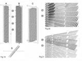
- At least one surface of the lamellae is additionally developed with placed thereon micro panels, uniformly manufactured, in particular by injection to the surface of the lamellae or panels.
- the micro panels are preferably produced as ribs, preferably irregularly shaped, preferably with irregularly shaped edges and surfaces.
- the micro panels are manufactured so that their longitudinal axis is not perpendicular to the longitudinal axis of the lamellae.
- the angle between the axis of the micro panels and the lamellae is a variable angle along the length of the lamellae.
- the height of the micro panels is not less than 5mm and it is not more than 90% of the depth of the lamellae.
- the panel-layer system for thermal insulation of the shaded surface according to the invention is intended for use on all types of roof windows (as well as vertical windows) in order to block the access of sun's rays to the surface of the window pane and thus prevent it from heating up and transmitting heat to the interior of the room.
- the panel-layer system for thermal insulation of the shaded surface according to the invention is intended for use in residential, office and industrial rooms, wherever it is important to maintain thermal comfort of a room while maintaining a sufficiently high intensity of interior lighting by means of daylight.
- the panel-layer system for thermal insulation of the shaded surface comprises mountable to the outer side of the building envelope, especially a window, especially a roof window, a supporting construction in the form of rigid and non-deformable rails, to which permanently mounted are lamellae, whose edge, outer in relation to the shielded building envelope, has an irregular shape.
- the lamellae are inserted into notches made in the supporting construction and are additionally glued to it.
- the inclination angle of each lamella is constant, while for the lamellae placed at the top of the building envelope the inclination angle is 38° with respect to the plane of the envelope and decreases towards the bottom of the envelope so that the lowest lamella inclines at an angle of 25°.
- the inclination angle of the lamellae varies linearly from the highest to the lowest by 13°/number of lamellae and the distance between the lamellae measured along the edge of the supporting construction is the distance of the outermost lamellae/number of lamellae.
- the supporting construction shall be mounted on the building envelope so that an air cavity of 10 mm wide is maintained between the envelope, mounted to it lamellae, and the plane of the building envelope.
- the supporting construction and the lamellae are made of plastic, the former is made of Pet plastic, while the latter are cut out from Plexiglas.
- the outer edge of the lamellae is sinusoidal in shape.
- the panel-layer system for thermal insulation of the shaded surface comprises mountable to the outer side of the building envelope, especially a window, especially a roof window, a supporting construction in the form of rigid and non-deformable rails, to which permanently mounted are lamellae, whose edge, outer in relation to the shielded building envelope, has an irregular shape.
- the lamellae are inserted into notches made in the supporting construction.
- the inclination angle of each lamella is constant, while for the lamellae placed at the top of the building envelope the inclination angle is 37,03° with respect to the plane of the envelope and decreases towards the bottom of the envelope so that the lowest lamella inclines at the angle of 25,71°.
- the difference in inclination of the top and bottom lamella is 13°, successive lamellae have a different inclination angle which changes for each lamella by 13° divided by the number of lamellae from top to bottom of the window and the distance between the lamellae measured along the edge of the supporting construction is the distance of the outermost lamellae divided by number of lamellae.
- the supporting construction shall be mounted to the building envelope so that an air cavity of 100 mm wide is maintained between the envelope, mounted to it lamellae, and the plane of the building envelope.
- the supporting construction is mounted outside the window in such a way that rigid and non-deformable rails are snapped in cantilevers screwed into the upper part of the frame of the building envelope, especially a window, and are supported by two cantilevers that block the movement of the blind laterally and in the vertical plane of the envelope, especially the window frame in its lower part.
- the supporting construction and the lamellae are made of plastic, the former is made of Pet plastic, while the latter are cut out from Plexiglas.
- the outer edge of the lamellae has a shape selected from a sinusoid, irregular wave, geometric figures placed alternately on the edge of the lamellae, in particular at least parts of a circle, rectangle, triangle or other polygons.
- the panel-layer system for thermal insulation of the shaded surface according to the invention remains transparent throughout its use, allowing natural visible light into the room.
- the highly moving sun and the operation of the sun's rays during peak daylight hours is limited by the fact that the sun's rays must penetrate at least a few lamellae to reach the building envelope and the interior of the room.
- the largest heat emission resulting from this occurs in the cavity between the lamellae and the building envelope, the presence of the cavity and its free ventilation precludes heating of the envelope and the room behind it.
- the panel-layer system for thermal insulation of the shaded surface comprises mountable to the outer side of the building envelope, especially a window, especially a roof window, a supporting construction in the form of rigid and non-deformable rails, to which permanently mounted are lamellae, whose edge, outer in relation to the shielded building envelope, has an irregular shape.
- the lamellae are made up of panels inserted into the rails and are inserted into notches in the supporting construction and are additionally glued to it.
- the inclination angle of each lamella is constant, while for the lamellae placed at the top of the building envelope the inclination angle is 37,03° with respect to the plane of the envelope and decreases towards the bottom of the envelope so that the lowest lamella inclines at the angle of 25,71°.
- the difference in inclination of the top and bottom lamella is 13°, successive lamellae have a different inclination angle which changes for each lamella by 13° divided by the number of lamellae from top to bottom of the window and the distance between the lamellae measured along the edge of the supporting construction is the distance of the outermost lamellae divided by number of lamellae.
- the supporting construction shall be mounted to the building envelope so that an air cavity of 100 mm wide is maintained between the envelope, mounted to it lamellae, and the plane of the building envelope.
- the supporting construction is mounted outside the window in such a way that rigid and non-deformable rails are snapped in cantilevers screwed into the upper part of the frame of the envelope, especially a window, and are supported by two cantilevers that block the movement of the blind laterally and in the vertical plane of the envelope, especially the window frame in its lower part.
- the supporting construction and the lamellae are made of plastic, the former is made of Pet plastic, while the latter are cut out from Plexiglas.
- each lamella is covered with a solar reflective film with a transparency of at least 20%, but not more than 90% of the ability to retain light radiation.
- the limitation of transparency is implemented in such a way that one surface of the lamellae is covered with a sun protection film with a shading degree of 20 to 90%.
- the outer edge of the lamellae has a shape selected from a sinusoid, irregular wave, geometric figures placed alternately on the edge of the lamellae, in particular at least parts of a circle, rectangle, triangle or other polygons.
- the panels are provided with additional one-sided longitudinal protrusions, made of the same material as the panels. The protrusions are firmly connected to the lamellae and are directed at an acute or near-right angle to the surface of the panels.
- each lamella is constant, while for the lamellae placed at the top of the building envelope the inclination angle is 70° with respect to the plane of the envelope and decreases towards the bottom of the envelope so that the lowest lamella inclines at an angle of 55° at least a few lamellae to reach the building envelope and the interior of the room.
- the largest heat emission resulting from this occurs in the cavity between the lamellae and the building envelope, the presence of the cavity and its free ventilation precludes heating of the envelope and the room behind it.
- the panel-layer system for thermal insulation of the shaded surface according to the invention is intended for use on all types of roof windows (as well as vertical windows) in order to block the access of sun's rays to the surface of the window pane and thus prevent it from heating up and transmitting heat to the interior of the room.
- the panel-layer system for thermal insulation of the shaded surface according to the invention is intended for use in residential, office and industrial rooms, wherever it is important to maintain thermal comfort of a room while maintaining a sufficiently high intensity of interior lighting by means of daylight.
- the panel-layer system for thermal insulation of the shaded surface comprises mountable to the outer side of the building envelope, especially a window, especially a roof window, a supporting construction in the form of rigid and non-deformable rails, to which permanently mounted are lamellae, whose edge, outer in relation to the shielded building envelope, has an irregular shape.
- the lamellae are inserted into notches in the supporting construction.
- the inclination angle of each lamella is constant, while for the lamellae placed at the top of the building envelope the inclination angle is 37,03° with respect to the plane of the envelope and decreases towards the bottom of the envelope so that the lowest lamella inclines at the angle of 25,71°.
- the difference in inclination of the top and bottom lamella is 13°, successive lamellae have a different inclination angle which changes for each lamella by 13° divided by the number of lamellae from top to bottom of the window and the distance between the lamellae measured along the edge of the supporting construction is the distance of the outermost lamellae divided by number of lamellae.
- the supporting construction shall be mounted to the building envelope so that an air cavity of 100 mm wide is maintained between the envelope, mounted to it lamellae, and the plane of the building envelope.
- the supporting construction and the lamellae are made of plastic, the former is made of Pet plastic, while the latter are cut out from Plexiglas.
- each lamella is covered with a solar reflective film with a transparency of at least 20%, but not more than 90% of the ability to retain light radiation.
- the limitation of transparency is implemented in such a way that one surface of the lamellae is covered with a sun protection film with a shading degree of 20 to 90%.
- One surface of the lamellae is additionally developed with placed thereon micro panels, uniformly manufactured, in particular by injection to the surface of the lamellae or panels.
- the micro panels are preferably produced as ribs, preferably irregularly shaped, preferably irregularly shaped edges and surfaces.
- the micro panels are manufactured so that their longitudinal axis is not perpendicular to the longitudinal axis of the lamellae.
- the angle between the axis of the micro panels and the lamellae is a variable angle along the length of the lamellae.
- the height of the micro panels is not less than 5mm and it is not more than 90% of the depth of the lamellae.
- the outer edge of the lamellae has a shape selected from a sinusoid, irregular wave, geometric figures placed alternately on the edge of the lamellae, in particular at least parts of a circle, rectangle, triangle or other polygons.
- the panel-layer system for thermal insulation of the shaded surface comprises mountable to the outer side of the building envelope, especially a window, especially a roof window, a supporting construction in the form of rigid and non-deformable rails, to which permanently mounted are lamellae, whose edge, outer in relation to the shielded building envelope, has an irregular shape.
- the lamellas are made up of panels inserted e.g. into aluminium rails and inserted into the notches of the supporting construction and additionally glued.
- the inclination angle of each lamella is constant, while for the lamellae placed at the top of the building envelope the inclination angle is 37,03° with respect to the plane of the envelope and decreases towards the bottom of the envelope so that the lowest lamella inclines at the angle of 25,71°.
- the difference in inclination of the top and bottom lamella is 13°, successive lamellae have a different inclination angle which changes for each lamella by 13° divided by the number of lamellae from top to bottom of the window and the distance between the lamellae measured along the edge of the supporting construction is the distance of the outermost lamellae divided by number of lamellae.
- the supporting construction is mounted outside the window in such a way that rigid and non-deformable rails are snapped in cantilevers screwed into the upper part of the frame of the envelope, especially a window, and are supported by two cantilevers that block the movement of the blind laterally and in the vertical plane of the envelope, especially the window frame in its lower part.
- the supporting construction and the lamellae are made of plastic, where the former is made of Pet plastic, while the latter are cut out from Plexiglas.
- each lamella is covered with a solar reflective film with a transparency of at least 20%, but not more than 90% of the ability to retain light radiation.
- the limitation of transparency is implemented in such a way that one surface of the lamellae is covered with a sun protection film with a shading degree of 20 to 90%.
- the outer edge of the lamellae w has a shape selected from a sinusoid, irregular wave, geometric figures placed alternately on the edge of the lamellae, in particular at least parts of a circle, rectangle, triangle or other polygons.
- the panels are provided with additional one-sided longitudinal protrusions, made of the same material as the panels. The protrusions are firmly connected to the lamellae and are directed at an acute or near-right angle to the surface of the panels.
- One surface of the lamellae is additionally developed with placed thereon micro panels, uniformly manufactured, in particular by injection to the surface of the lamellae or panels.
- the micro panels are preferably produced as ribs, preferably irregularly shaped, preferably irregularly shaped edges and surfaces.
- the micro panels are manufactured so that their longitudinal axis is not perpendicular to the longitudinal axis of the lamellae.
- the angle between the axis of the micro panels and the lamellae is a variable angle along the length of the lamellae.
- the height of the micro panels is not less than 5mm and it is not more than 90% of the depth of the lamellae.
- the panel-layer system for thermal insulation of the shaded surface according to the invention remains transparent throughout its use, allowing natural visible light into the room.
- the highly moving sun and the operation of the sun's rays during peak daylight hours is limited by the fact that the sun's rays must penetrate at least a few lamellae to reach the building envelope and the interior of the room.
- the largest heat emission resulting from this occurs in the cavity between the lamellae and the building envelope, the presence of the cavity and its free ventilation precludes heating of the envelope and the room behind it.
Landscapes
- Engineering & Computer Science (AREA)
- Architecture (AREA)
- Structural Engineering (AREA)
- Civil Engineering (AREA)
- Building Environments (AREA)
- Blinds (AREA)
Claims (15)
- Schichtsystem zur Wärmedämmung einer beschatteten Fläche, umfassend eine Stützkonstruktion in Form von mindestens zwei starren und nicht verformbaren Schienen, wobei die Stützkonstruktion an der anderen Seite der Gebäudehülle, insbesondere eines Fensters, insbesondere Dachfensters, montiert werden kann, eine Vielzahl von Lamellen, die dauerhaft an der Stützkonstruktion montiert sind, wobei die Lamellen in Kerben der Stützkonstruktion eingesetzt und zusätzlich verklebt sind, und wobei der Neigungswinkel jeder Lamelle konstant ist, während für die an der Oberseite der Gebäudehülle angeordneten Lamellen der Neigungswinkel weniger als 70°, vorzugsweise 38°, in Bezug auf die Ebene der Hülle beträgt und in Richtung der Unterseite der Hülle abnimmt, so dass die unterste Lamelle in einem Winkel von nicht mehr als 45°, vorzugsweise 25°, geneigt ist, wobei der Neigungswinkel der Lamellen linear von der höchsten zur niedrigsten durch 13 geteilt durch die Anzahl der Lamellen und den Abstand zwischen den Lamellen, gemessen entlang der Kante der Stützkonstruktion, variiert. Die Konstruktion ist der Abstand der äußersten Lamellen geteilt durch die Anzahl der Lamellen, und die Stützkonstruktion ist so angepasst, dass sie an der Gebäudehülle befestigt werden kann, sodass zwischen der Stützkonstruktion und der Ebene der Gebäudehülle ein Lufthohlraum von mindestens 10 mm und höchstens 100 mm Breite erhalten bleibt.
- System nach Anspruch 1, dadurch gekennzeichnet, dass die Tragkonstruktion außen am Fenster derart montierbar ist, dass mindestens zwei starre und unverformbare Schienen in Ausleger einrasten, die im oberen Teil des Rahmens der Gebäudehülle, insbesondere des Fensters, verschraubt sind, und von zwei Auslegern getragen werden, die die Bewegung des Rollos seitlich und in der vertikalen Ebene der Hülle, insbesondere des Fensterrahmens, in seinem unteren Teil blockieren.
- System nach Anspruch 1 oder 2, wobei die Außenkante der Lamellen eine unregelmäßige Form aufweist.
- System nach Anspruch 1 oder 2 oder 3, wobei die Trägerkonstruktion und die Lamellen aus einem Kunststoffmaterial, ausgewählt aus Pet-Kunststoff, bestehen, während die Lamellen aus Plexiglas ausgeschnitten sind.
- System nach Anspruch 1 oder 2 oder 3 oder 4, wobei: mindestens eine Oberfläche jeder Lamelle mit einer Sonnenlicht reflektierenden Folie bedeckt ist, die eine Transparenz von mindestens 20 %, aber nicht mehr als 90 % der Fähigkeit zum Zurückhalten von Lichtstrahlung aufweist, und zwar derart, dass eine Oberfläche der Lamellen mit Aluminiumstaub besprüht ist, der auf der Oberfläche der Lamellen fixiert ist.
- System nach Anspruch 1 oder 2 oder 3 oder 4, wobei: mindestens eine Oberfläche der Lamellen mit einer Sonnenschutzfolie mit einem Verdunkelungsgrad zwischen 20 und 90 % bespannt ist.
- System nach einem der vorhergehenden Ansprüche, wobei die Außenkante der Lamellen eine Form aufweist, die ausgewählt ist aus einer Sinuskurve, einer unregelmäßigen Welle, abwechselnd auf der Kante der Lamellen angeordneten geometrischen Figuren, insbesondere zumindest Teilen eines Kreises, Rechtecks, Dreiecks oder anderen Polygonen.
- System nach einem der vorhergehenden Ansprüche, wobei: die Lamellen so hergestellt sind, dass sie eine Plattenstruktur haben und aus zusammengefügten und in einen Schlitz in der Montagelatte der Paneele eingesetzten Paneelen aufgebaut sind, die Enden der Montagelatte an starren und unverformbaren Schienen befestigt sind, die eine Tragkonstruktion bilden, und die Paneele vorzugsweise formschlüssig, schnappend, verbunden sind.
- System nach Anspruch 1 oder 2 oder 3 oder 4 oder 5 oder 6 oder 7 oder 8, wobei die Lamellen derart ausgebildet sind, dass sie eine Plattenstruktur aufweisen und aus aneinandergefügten Platten aufgebaut sind, die mit einem Längsschlitz mit nicht rotierendem Querschnitt versehen sind, durch den die Befestigungsleiste der Platten verläuft.
- System nach Anspruch 8 oder 9, wobei die Montageleiste im Querschnitt eine C-Grundform mit mindestens einer zusätzlichen Längsaussparung aufweist, wobei jedes Paneel mindestens auf einer Seite eine mit mindestens einer zusätzlichen Längsaussparung zusammenwirkende Längsrippe, beispielsweise mindestens eine einseitige Nut, aufweist.
- System nach einem der vorhergehenden Ansprüche, wobei mindestens eine Oberfläche der Lamellen zusätzlich mit darauf angeordneten, einheitlich hergestellten Mikroplatten ausgebildet ist, indem diese in die Oberfläche der Lamellen eingespritzt werden.
- System nach Anspruch 11, wobei die Mikroplatten als unregelmäßig geformte Rippen, vorzugsweise unregelmäßig geformte Kanten und Flächen ausgebildet sind.
- System nach Anspruch 11 oder 12, wobei: die Mikroplatten so hergestellt sind, dass ihre Längsachse nicht senkrecht zur Längsachse der Lamellen verläuft, und der Winkel zwischen der Achse der Mikroplatten und der Lamellen ein variabler Winkel entlang der Länge der Lamellen ist.
- System nach Anspruch 11 oder 12 oder 13, wobei die Höhe der Mikroplatten höher als 5 mm ist und 90 % der Tiefe der Lamellen nicht überschreitet.
- System nach einem der vorhergehenden Ansprüche, wobei die Form, die Farbe sowie der Grad der Lichtdurchlässigkeit für jede Lamelle und/oder für jedes Paneel variiert werden.
Applications Claiming Priority (1)
| Application Number | Priority Date | Filing Date | Title |
|---|---|---|---|
| PL437721A PL437721A1 (pl) | 2021-04-28 | 2021-04-28 | Układ panelowo-warstwowy, do izolacji termicznej powierzchni ocienionej |
Publications (3)
| Publication Number | Publication Date |
|---|---|
| EP4144931A1 EP4144931A1 (de) | 2023-03-08 |
| EP4144931B1 true EP4144931B1 (de) | 2025-04-09 |
| EP4144931C0 EP4144931C0 (de) | 2025-04-09 |
Family
ID=83808206
Family Applications (1)
| Application Number | Title | Priority Date | Filing Date |
|---|---|---|---|
| EP22169747.7A Active EP4144931B1 (de) | 2021-04-28 | 2022-04-25 | Paneel-system zur thermischen isolierung einer beschatteten oberfläche |
Country Status (3)
| Country | Link |
|---|---|
| US (1) | US12595660B2 (de) |
| EP (1) | EP4144931B1 (de) |
| PL (1) | PL437721A1 (de) |
Families Citing this family (2)
| Publication number | Priority date | Publication date | Assignee | Title |
|---|---|---|---|---|
| PL437721A1 (pl) | 2021-04-28 | 2022-10-31 | Adam Kalinowski | Układ panelowo-warstwowy, do izolacji termicznej powierzchni ocienionej |
| US20240366957A1 (en) * | 2023-05-05 | 2024-11-07 | Randy Mersky | Customizable tanning apparatus |
Citations (1)
| Publication number | Priority date | Publication date | Assignee | Title |
|---|---|---|---|---|
| JP2008223346A (ja) * | 2007-03-13 | 2008-09-25 | Misawa Homes Co Ltd | 庇及び建物 |
Family Cites Families (14)
| Publication number | Priority date | Publication date | Assignee | Title |
|---|---|---|---|---|
| US2723716A (en) * | 1953-02-14 | 1955-11-15 | Berni Oreste | Double sliding louvre board venetian blind, designed to decrease the penetration of light when closed |
| US2859494A (en) * | 1955-03-15 | 1958-11-11 | Clair I Hull | Awning |
| US6371191B1 (en) * | 2001-01-19 | 2002-04-16 | Cooper C. Woodring | Decorative venetian blinds |
| US20030221800A1 (en) * | 2002-05-28 | 2003-12-04 | Jones Marvin L. | Louver blinds |
| KR20040022628A (ko) | 2002-09-09 | 2004-03-16 | 니엔 메이드 엔터프라이즈 코오퍼레이션 | 구분식 블라인드 |
| DE102008002219B4 (de) * | 2008-06-04 | 2014-11-20 | Mediabiose Gmbh | Jalousievorrichtung und Anordnung mit einer Mehrheit von Jalousievorrichtungen |
| KR20150025474A (ko) | 2013-08-29 | 2015-03-10 | 주식회사 윈플러스 | 횡 방향 각도조절형 블라인드지 |
| EP3080378B1 (de) * | 2013-12-13 | 2019-05-15 | Mare Beheer B.V. | Jalousie |
| CN204609717U (zh) * | 2015-05-07 | 2015-09-02 | 上海斯诺博金属构件发展有限公司 | 一种立式复合遮阳板 |
| KR20160131565A (ko) | 2015-05-08 | 2016-11-16 | 주식회사 루버텍코리아 | 창호 일체형 루버 블라인드 |
| US20180023338A1 (en) * | 2016-07-22 | 2018-01-25 | Bruce M. Werner | Various Systems of Sculptural Slats and Methods of Manufacture Thereof |
| CN208564410U (zh) | 2018-07-06 | 2019-03-01 | 方霁涛 | 一种遮光效果可调的多层卷式窗帘 |
| GR20180200111U (el) | 2018-09-04 | 2020-05-11 | Μιχαηλ Λομβαρδεας | Συστημα αναρτησης ανακλινομενων και πτυσσομενων περσιδων σκιασης |
| PL437721A1 (pl) | 2021-04-28 | 2022-10-31 | Adam Kalinowski | Układ panelowo-warstwowy, do izolacji termicznej powierzchni ocienionej |
-
2021
- 2021-04-28 PL PL437721A patent/PL437721A1/pl unknown
-
2022
- 2022-04-25 EP EP22169747.7A patent/EP4144931B1/de active Active
- 2022-04-27 US US17/660,840 patent/US12595660B2/en active Active
Patent Citations (1)
| Publication number | Priority date | Publication date | Assignee | Title |
|---|---|---|---|---|
| JP2008223346A (ja) * | 2007-03-13 | 2008-09-25 | Misawa Homes Co Ltd | 庇及び建物 |
Also Published As
| Publication number | Publication date |
|---|---|
| US20220349183A1 (en) | 2022-11-03 |
| PL437721A1 (pl) | 2022-10-31 |
| EP4144931A1 (de) | 2023-03-08 |
| US12595660B2 (en) | 2026-04-07 |
| EP4144931C0 (de) | 2025-04-09 |
Similar Documents
| Publication | Publication Date | Title |
|---|---|---|
| US6239910B1 (en) | Mini-optical light shelf daylighting system | |
| US4035539A (en) | Structural panel | |
| CA1171350A (en) | Reflective insulating blinds for windows and the like | |
| EP4144931B1 (de) | Paneel-system zur thermischen isolierung einer beschatteten oberfläche | |
| US6714352B2 (en) | Mini-optical light shelf daylighting system | |
| US20090199888A1 (en) | Sun protection device with angle-selective transmission properties | |
| EP1920120B1 (de) | Bewegliches sonnenschutzfassadensystem mit zwei schichten | |
| CN102459798A (zh) | 用于窗和类似对象的能量控制装置 | |
| US2545906A (en) | Multiple glass sheet glazing unit having enclosed angled metal slats | |
| EP0793761B1 (de) | Gestufte lamelle für gerichtete lichtstrahlung | |
| RU2105934C1 (ru) | Устройство для улавливания солнечной энергии и ее передачи к подлежащей нагреву приемной среде | |
| EP2458127A2 (de) | Tageslichtrollladen | |
| WO2011159530A1 (en) | Curved light shelf system for daylighting an interior space | |
| EP2336479B1 (de) | Sonnenschutzsystem mit beweglichen Lamellen | |
| US20160123000A1 (en) | Building envelope solar heat and daylighting control system | |
| US3072230A (en) | Screen wall construction | |
| US3378955A (en) | Sun screen | |
| Beck et al. | Making better use of natural light with a light-redirecting double-glazing system | |
| JP2001060407A (ja) | 昼光利用システム | |
| US10119667B1 (en) | Light-redirecting optical daylighting system | |
| US3260026A (en) | Solar screen | |
| JP6788464B2 (ja) | 採光装置 | |
| KR20120077984A (ko) | 수동식 다축 동력 전달 장치와 이를 이용한 가동형 차양 또는 격자 난간 | |
| KR20220159092A (ko) | 블라인드 슬랫 및 이를 포함하는 블라인드 | |
| Laar et al. | German developments in guidance systems: an overview daylight |
Legal Events
| Date | Code | Title | Description |
|---|---|---|---|
| PUAI | Public reference made under article 153(3) epc to a published international application that has entered the european phase |
Free format text: ORIGINAL CODE: 0009012 |
|
| STAA | Information on the status of an ep patent application or granted ep patent |
Free format text: STATUS: THE APPLICATION HAS BEEN PUBLISHED |
|
| AK | Designated contracting states |
Kind code of ref document: A1 Designated state(s): AL AT BE BG CH CY CZ DE DK EE ES FI FR GB GR HR HU IE IS IT LI LT LU LV MC MK MT NL NO PL PT RO RS SE SI SK SM TR |
|
| STAA | Information on the status of an ep patent application or granted ep patent |
Free format text: STATUS: REQUEST FOR EXAMINATION WAS MADE |
|
| 17P | Request for examination filed |
Effective date: 20230830 |
|
| RBV | Designated contracting states (corrected) |
Designated state(s): AL AT BE BG CH CY CZ DE DK EE ES FI FR GB GR HR HU IE IS IT LI LT LU LV MC MK MT NL NO PL PT RO RS SE SI SK SM TR |
|
| GRAP | Despatch of communication of intention to grant a patent |
Free format text: ORIGINAL CODE: EPIDOSNIGR1 |
|
| STAA | Information on the status of an ep patent application or granted ep patent |
Free format text: STATUS: GRANT OF PATENT IS INTENDED |
|
| INTG | Intention to grant announced |
Effective date: 20241111 |
|
| GRAS | Grant fee paid |
Free format text: ORIGINAL CODE: EPIDOSNIGR3 |
|
| GRAA | (expected) grant |
Free format text: ORIGINAL CODE: 0009210 |
|
| STAA | Information on the status of an ep patent application or granted ep patent |
Free format text: STATUS: THE PATENT HAS BEEN GRANTED |
|
| AK | Designated contracting states |
Kind code of ref document: B1 Designated state(s): AL AT BE BG CH CY CZ DE DK EE ES FI FR GB GR HR HU IE IS IT LI LT LU LV MC MK MT NL NO PL PT RO RS SE SI SK SM TR |
|
| REG | Reference to a national code |
Ref country code: GB Ref legal event code: FG4D |
|
| REG | Reference to a national code |
Ref country code: CH Ref legal event code: EP |
|
| REG | Reference to a national code |
Ref country code: DE Ref legal event code: R096 Ref document number: 602022012776 Country of ref document: DE |
|
| REG | Reference to a national code |
Ref country code: IE Ref legal event code: FG4D |
|
| U01 | Request for unitary effect filed |
Effective date: 20250501 |
|
| U07 | Unitary effect registered |
Designated state(s): AT BE BG DE DK EE FI FR IT LT LU LV MT NL PT RO SE SI Effective date: 20250507 |
|
| U20 | Renewal fee for the european patent with unitary effect paid |
Year of fee payment: 4 Effective date: 20250604 |
|
| PG25 | Lapsed in a contracting state [announced via postgrant information from national office to epo] |
Ref country code: ES Free format text: LAPSE BECAUSE OF FAILURE TO SUBMIT A TRANSLATION OF THE DESCRIPTION OR TO PAY THE FEE WITHIN THE PRESCRIBED TIME-LIMIT Effective date: 20250409 |
|
| PG25 | Lapsed in a contracting state [announced via postgrant information from national office to epo] |
Ref country code: NO Free format text: LAPSE BECAUSE OF FAILURE TO SUBMIT A TRANSLATION OF THE DESCRIPTION OR TO PAY THE FEE WITHIN THE PRESCRIBED TIME-LIMIT Effective date: 20250709 Ref country code: GR Free format text: LAPSE BECAUSE OF FAILURE TO SUBMIT A TRANSLATION OF THE DESCRIPTION OR TO PAY THE FEE WITHIN THE PRESCRIBED TIME-LIMIT Effective date: 20250710 |
|
| PG25 | Lapsed in a contracting state [announced via postgrant information from national office to epo] |
Ref country code: PL Free format text: LAPSE BECAUSE OF FAILURE TO SUBMIT A TRANSLATION OF THE DESCRIPTION OR TO PAY THE FEE WITHIN THE PRESCRIBED TIME-LIMIT Effective date: 20250409 |
|
| PG25 | Lapsed in a contracting state [announced via postgrant information from national office to epo] |
Ref country code: HR Free format text: LAPSE BECAUSE OF FAILURE TO SUBMIT A TRANSLATION OF THE DESCRIPTION OR TO PAY THE FEE WITHIN THE PRESCRIBED TIME-LIMIT Effective date: 20250409 |
|
| PG25 | Lapsed in a contracting state [announced via postgrant information from national office to epo] |
Ref country code: RS Free format text: LAPSE BECAUSE OF FAILURE TO SUBMIT A TRANSLATION OF THE DESCRIPTION OR TO PAY THE FEE WITHIN THE PRESCRIBED TIME-LIMIT Effective date: 20250709 |
|
| PG25 | Lapsed in a contracting state [announced via postgrant information from national office to epo] |
Ref country code: IS Free format text: LAPSE BECAUSE OF FAILURE TO SUBMIT A TRANSLATION OF THE DESCRIPTION OR TO PAY THE FEE WITHIN THE PRESCRIBED TIME-LIMIT Effective date: 20250809 |
|
| REG | Reference to a national code |
Ref country code: CH Ref legal event code: H13 Free format text: ST27 STATUS EVENT CODE: U-0-0-H10-H13 (AS PROVIDED BY THE NATIONAL OFFICE) Effective date: 20251125 |
|
| PG25 | Lapsed in a contracting state [announced via postgrant information from national office to epo] |
Ref country code: SM Free format text: LAPSE BECAUSE OF FAILURE TO SUBMIT A TRANSLATION OF THE DESCRIPTION OR TO PAY THE FEE WITHIN THE PRESCRIBED TIME-LIMIT Effective date: 20250409 |
|
| PG25 | Lapsed in a contracting state [announced via postgrant information from national office to epo] |
Ref country code: CH Free format text: LAPSE BECAUSE OF NON-PAYMENT OF DUE FEES Effective date: 20250430 |
|
| PG25 | Lapsed in a contracting state [announced via postgrant information from national office to epo] |
Ref country code: CZ Free format text: LAPSE BECAUSE OF FAILURE TO SUBMIT A TRANSLATION OF THE DESCRIPTION OR TO PAY THE FEE WITHIN THE PRESCRIBED TIME-LIMIT Effective date: 20250409 |
|
| PG25 | Lapsed in a contracting state [announced via postgrant information from national office to epo] |
Ref country code: SK Free format text: LAPSE BECAUSE OF FAILURE TO SUBMIT A TRANSLATION OF THE DESCRIPTION OR TO PAY THE FEE WITHIN THE PRESCRIBED TIME-LIMIT Effective date: 20250409 |
|
| PG25 | Lapsed in a contracting state [announced via postgrant information from national office to epo] |
Ref country code: MC Free format text: LAPSE BECAUSE OF FAILURE TO SUBMIT A TRANSLATION OF THE DESCRIPTION OR TO PAY THE FEE WITHIN THE PRESCRIBED TIME-LIMIT Effective date: 20250409 |
|
| PLBE | No opposition filed within time limit |
Free format text: ORIGINAL CODE: 0009261 |
|
| STAA | Information on the status of an ep patent application or granted ep patent |
Free format text: STATUS: NO OPPOSITION FILED WITHIN TIME LIMIT |
|
| REG | Reference to a national code |
Ref country code: CH Ref legal event code: L10 Free format text: ST27 STATUS EVENT CODE: U-0-0-L10-L00 (AS PROVIDED BY THE NATIONAL OFFICE) Effective date: 20260218 |
|
| 26N | No opposition filed |
Effective date: 20260112 |
|
| PG25 | Lapsed in a contracting state [announced via postgrant information from national office to epo] |
Ref country code: IE Free format text: LAPSE BECAUSE OF NON-PAYMENT OF DUE FEES Effective date: 20250425 |