EP4144939A1 - Auvent pour véhicule - Google Patents
Auvent pour véhicule Download PDFInfo
- Publication number
- EP4144939A1 EP4144939A1 EP22796019.2A EP22796019A EP4144939A1 EP 4144939 A1 EP4144939 A1 EP 4144939A1 EP 22796019 A EP22796019 A EP 22796019A EP 4144939 A1 EP4144939 A1 EP 4144939A1
- Authority
- EP
- European Patent Office
- Prior art keywords
- housing
- awning
- pole
- bracket
- vertical rod
- Prior art date
- Legal status (The legal status is an assumption and is not a legal conclusion. Google has not performed a legal analysis and makes no representation as to the accuracy of the status listed.)
- Withdrawn
Links
- 230000004308 accommodation Effects 0.000 claims description 28
- 238000003780 insertion Methods 0.000 claims description 24
- 230000037431 insertion Effects 0.000 claims description 24
- 230000003014 reinforcing effect Effects 0.000 claims description 9
- 125000006850 spacer group Chemical group 0.000 claims description 5
- 229910052782 aluminium Inorganic materials 0.000 claims description 3
- XAGFODPZIPBFFR-UHFFFAOYSA-N aluminium Chemical compound [Al] XAGFODPZIPBFFR-UHFFFAOYSA-N 0.000 claims description 3
- 239000000470 constituent Substances 0.000 description 12
- 230000002452 interceptive effect Effects 0.000 description 6
- 230000014509 gene expression Effects 0.000 description 2
- 239000000463 material Substances 0.000 description 2
- 229910052751 metal Inorganic materials 0.000 description 2
- 239000002184 metal Substances 0.000 description 2
- 238000000034 method Methods 0.000 description 2
- 230000002093 peripheral effect Effects 0.000 description 2
- 230000003252 repetitive effect Effects 0.000 description 2
- 239000011347 resin Substances 0.000 description 2
- 229920005989 resin Polymers 0.000 description 2
- 238000005452 bending Methods 0.000 description 1
- 230000008878 coupling Effects 0.000 description 1
- 238000010168 coupling process Methods 0.000 description 1
- 238000005859 coupling reaction Methods 0.000 description 1
- 230000000694 effects Effects 0.000 description 1
- 238000012986 modification Methods 0.000 description 1
- 230000004048 modification Effects 0.000 description 1
Images













Classifications
-
- E—FIXED CONSTRUCTIONS
- E04—BUILDING
- E04H—BUILDINGS OR LIKE STRUCTURES FOR PARTICULAR PURPOSES; SWIMMING OR SPLASH BATHS OR POOLS; MASTS; FENCING; TENTS OR CANOPIES, IN GENERAL
- E04H15/00—Tents or canopies, in general
- E04H15/02—Tents combined or specially associated with other devices
- E04H15/06—Tents at least partially supported by vehicles
- E04H15/08—Trailer awnings or the like
-
- E—FIXED CONSTRUCTIONS
- E04—BUILDING
- E04H—BUILDINGS OR LIKE STRUCTURES FOR PARTICULAR PURPOSES; SWIMMING OR SPLASH BATHS OR POOLS; MASTS; FENCING; TENTS OR CANOPIES, IN GENERAL
- E04H15/00—Tents or canopies, in general
- E04H15/32—Parts, components, construction details, accessories, interior equipment, specially adapted for tents, e.g. guy-line equipment, skirts, thresholds
- E04H15/34—Supporting means, e.g. frames
- E04H15/44—Supporting means, e.g. frames collapsible, e.g. breakdown type
- E04H15/46—Supporting means, e.g. frames collapsible, e.g. breakdown type telescoping and foldable
Definitions
- the present disclosure relates to an awning for a vehicle.
- an awning serves as a tent, a sun shelter, a weatherproof tent, and the like.
- various types of awnings for vehicles have been developed, which may be installed more conveniently by using vehicles.
- An awning for a vehicle in the related art has a structure installed on a roof of the vehicle by using the vehicle as a part of a support.
- the awning for a vehicle may be installed on a roof rack of the vehicle and fixed by poles standing in a state in which the awning is unfolded when the awning is used.
- an awning for a vehicle which is capable of covering a sufficient region, being minimized in size when stored, and being easily installed on the vehicle or the like.
- An object of the present disclosure is to provide an awning for a vehicle, which is capable of being easily accommodated and minimized in volume when stored.
- Another object of the present disclosure is to provide an awning for a vehicle, which may be easily installed on a fixing object such as a vehicle.
- An embodiment of the present disclosure provides an awning for a vehicle, the awning including: a housing including an openable/closable internal space; a first pole assembly rotatably coupled to one side of the housing; a second pole assembly rotatably coupled to the other side of the housing; and a sun shelter configured to cover an upper surface of the first pole assembly and an upper surface of the second pole assembly, in which the first pole assembly, the second pole assembly, and the sun shelter are selectively accommodated in the housing or unfolded by rotating to the outside of the housing.
- an awning for a vehicle including: a housing including an openable/closable internal space; and a bracket module detachably provided on one surface of the housing and configured to fix the housing to a fixing object
- the bracket module includes: a first fixing bracket slidably inserted into one surface of the housing and fixed to a predetermined position; a second fixing bracket including a first fixing part detachably fixed to one surface of the first fixing bracket, and a first bent part bent and extending from one end of the first fixing part and detachably fastened to the fixing object; and a third fixing bracket including a second fixing part detachably coupled to one surface of the first fixing bracket, and a second bent part bent and extending from one end of the second fixing part and configured to come into contact with one surface of the first bent part.
- Still another embodiment of the present disclosure provides an awning for a vehicle, the awning including: a housing including an openable/closable internal space; and a bracket module detachably provided on one surface of the housing and configured to fix the housing to a fixing object
- the housing includes: a body connected to the bracket module and including an internal space; a first door rotatably coupled to an upper end of the body; and second doors rotatably coupled to two opposite ends of the body, in which the internal space of the body is exposed to the outside or closed as the first door and the second door rotate
- the bracket module includes: a first fixing bracket slidably inserted into one surface of the housing and fixed to a predetermined position; a second fixing bracket including a first fixing part detachably fixed to one surface of the first fixing bracket, and a first bent part bent and extending from one end of the first fixing part and detachably fastened to the fixing object; and a third fixing bracket including a second fixing part detachably coupled to one surface of the first fixing bracket
- the awning for a vehicle according to the embodiment of the present disclosure may be easily installed on the fixing object such as the vehicle.
- the awning for a vehicle according to the embodiment of the present disclosure may be easily accommodated and minimized in volume when stored.
- FIG. 1 is a schematic perspective view of an awning for a vehicle according to an embodiment of the present disclosure
- FIG. 2 is a schematic perspective view illustrating a state in which the awning for a vehicle according to the embodiment of the present disclosure is unfolded
- FIG. 3 is a schematic bottom perspective view of the awning illustrated in FIG. 2 .
- an awning 1 for a vehicle may include a housing 100 including an openable/closable internal space S (see FIG. 7 ), a first pole assembly 200 rotatably coupled to one side of the housing 100, a second pole assembly 300 rotatably coupled to the other side of the housing 100, and a sun shelter 400 configured to cover an upper surface of the first pole assembly 200 and an upper surface of the second pole assembly 300.
- the awning 1 for a vehicle may have a stored mode (see FIG. 1 ) and an unfolded mode (see FIG. 2 ).
- the stored mode may mean a state in which the first pole assembly 200, the second pole assembly 300, and the sun shelter 400 are accommodated in the housing 100.
- the unfolded mode may mean a state in which the first pole assembly 200, the second pole assembly 300, and the sun shelter 400 are unfolded and exposed to the outside of the housing 100.
- the housing 100 may be manufactured by using a material such as metal or resin having predetermined rigidity and have a column shape including the internal space S.
- the housing 100 may be made of aluminum and have a quadrangular column shape.
- the housing 100 may include: a body 110 including the internal space S and having one surface on which vehicle fixing brackets 10 configured to be installed on a vehicle are provided; a first door 120 rotatably coupled to an upper end of the body 110; and second doors 130 rotatably coupled to two opposite ends of the body 110.
- the vehicle fixing brackets 10 may be provided to bind the awning 1 for a vehicle to the vehicle.
- the vehicle fixing brackets 10 may be coupled to a roof of the vehicle.
- a separate structure such as a roof rack may be installed on the roof of the vehicle, and the vehicle fixing bracket 10 may be connected to the structure.
- the body 110 may include the internal space S.
- the first pole assembly 200, the second pole assembly 300, and the sun shelter 400 may be accommodated in the internal space S of the body 110.
- the body 110 may be provided as a structure having a longitudinal cross-section having a ' ' shape.
- a longitudinal direction may mean an x-axis direction based on FIG. 1
- a width direction may mean a y-axis direction based on FIG. 1
- a thickness direction may mean a z-axis direction based on FIG. 1 .
- the first door 120 may be rotatably connected to an upper end of the body 110. One end of the first door 120 may be coupled to the body 110 by means of hinges 121. In case that the first door 120 is coupled to the body 110, the body 110 and the first door 120 may define the column shape having the internal space S and opened overall at two opposite ends thereof. The first door 120 may selectively open or close a front side of the body 110.
- the second doors 130 may be rotatably connected to the two opposite ends of the body 110.
- the second doors 130 may selectively open or close the two opposite surfaces of the body 110.
- the first pole assembly 200 may be rotatably provided at one side of the housing 100.
- the first pole assembly 200 may rotate to be accommodated in the internal space S of the housing 100 (stored mode) or exposed to the outside of the housing 100 (unfolded mode).
- the first pole assembly 200 may include a first pole 220.
- the first pole 220 may include a first horizontal rod 221, a first vertical rod 222 rotatably connected to an end of the first horizontal rod 221, and a first auxiliary vertical rod 223 slidably connected to the first vertical rod 222.
- the first vertical rod 222 may rotate to be inserted into the first horizontal rod 221.
- the first auxiliary vertical rod 223 may slide to be inserted into the first vertical rod 222.
- the second pole assembly 300 may be rotatably provided at the other side of the housing 100.
- the second pole assembly 300 may rotate to be accommodated in the internal space S of the housing 100 (stored mode) or exposed to the outside of the housing 100 (unfolded mode).
- the second pole assembly 300 may include a second pole 310.
- the second pole 310 may be similar in structure to the first pole 220.
- the second pole 310 may include a second horizontal rod 311, a second vertical rod 312 rotatably connected to an end of the second horizontal rod 311, and a second auxiliary vertical rod 313 slidably connected to the second vertical rod 312.
- the second vertical rod 312 may rotate to be inserted into the second horizontal rod 311.
- the second auxiliary vertical rod 313 may slide to be inserted into the second vertical rod 312.
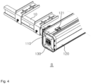
- FIG. 4 is an enlarged view of part A in FIG. 1 .
- the other end of the first door 120 may be detachably fastened to a bottom surface of the body 110.
- An opening/closing device 112 may be provided on the first door 120 and the body 110.
- a hook device 112a may be provided on the first door 120
- a catching device 112b may be provided on the bottom surface of the body 110.
- the first door 120 may selectively open or close the internal space S of the body 110 as the hook device 112a is fastened to the catching device 112b by being caught by the catching device 112b or separated from the catching device 112b.
- the configuration of the catching device and the configuration of the hook device may be substituted with various configurations commonly used in the art as long as the configuration of the catching device and the configuration of the hook device provide the structure capable of fastening the first door 120 to the body 110 so that the first door 120 is detachable.
- FIG. 5 is an enlarged view of part B in FIG. 1
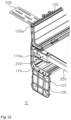
- FIG. 6 is an enlarged view of part C in FIG. 2
- FIG. 7 is a side view of FIG. 6 .
- the second doors 130 may be rotatably connected to the two opposite ends of the body 110.
- the second doors 130 may be configured to selectively open or close the two opposite ends of the housing 100.
- the second doors 130 may be rotatably connected to the bottom surfaces at the two opposite ends of the body 110.
- Fastening protrusions 131 may be provided on an outer peripheral surface of the second door 130. The fastening protrusions 131 may be inserted into or separated from first fastening holes 110a provided at the two opposite ends of the body 110 and second fastening holes 120a provided at the two opposite ends of the first door 120.
- the second doors 130 may close lateral sides of the housing 100 in the state in which the fastening protrusions 131 are inserted into the first fastening holes 110a and the second fastening holes 120a.
- the fastening protrusions 131 may be separated from the first fastening holes 110a and the second fastening holes 120a, and the door 130 may rotate downward. That is, in the unfolded mode, the first door 120 may rotate upward to open the front side of the housing 100, and the second door 130 may rotate downward to open the lateral sides of the housing 100.
- FIG. 8 is a partially exploded view of FIG. 6 .
- the first pole assembly 200 may include a first bracket 210 fixedly installed on an inner surface of the housing 100, and the first pole 220 rotatably connected to the first bracket 210 and configured to rotate to be accommodated in the housing 100 or exposed to the outside of the housing 100.
- the first bracket 210 may be configured to support the first pole 220 and fix the first pole 220 to the inner surface of the housing 100, more specifically, to an inner surface of the body 110.
- the first bracket 210 may include a first fixing piece 211 coupled to the inner surface of the body 110, a first bracket outer casing 212 seated on and coupled to an upper surface of the first fixing piece 211, first bracket inner casings 213 coupled to an upper inner surface and a lower inner surface of the first bracket outer casing 212, and a first stopper 214 configured to restrict a rotation angle of the first pole 220.
- An end of the first horizontal rod 221 of the first pole 220 may be rotatably connected to the first bracket 210 by means of a first rotary hinge 221a.
- the first horizontal rod 221 may rotate by means of the first rotary hinge 221a.
- a rotation radius of the first horizontal rod 221 may be adjusted by the first stopper 214.
- the first horizontal rod 221 may rotate until the first horizontal rod 221 comes into contact with the first stopper 214.
- the rotation of the first horizontal rod 221 may be restricted after the first horizontal rod 221 comes into contact with the first stopper 214.
- FIG. 9 is an enlarged view of part D in FIG. 3
- FIG. 10 is a partially exploded view of FIG. 9
- FIG. 11 is a partial perspective view illustrating a state in which the first door is removed from the awning for a vehicle according to the embodiment of the present disclosure.
- the second pole assembly 300 may include a second bracket 350 fixedly installed on the inner surface of the housing 100, and one or more second poles 310, 320, and 330 rotatably connected to the second bracket 350 and configured to rotate to be accommodated in the housing 100 or exposed to the outside of the housing 100.
- the second poles 310, 320, and 330 are provided as a plurality of second poles 310, 320, and 330, the plurality of second poles 310, 320, and 330 may have the same shape. Therefore, for convenience of description, a configuration of the second pole, which is designated by reference numeral '310' among the second poles, will be described below.
- the second bracket 350 may be configured to support the second pole 310 and fix the second pole 310 to the inner surface of the housing 100, more specifically, to the inner surface of the body 110.
- the second bracket 350 may include a second fixing piece 351 coupled to the inner surface of the body 110, a second bracket outer casing 352 seated on and coupled to an upper surface of the second fixing piece 351, and second bracket inner casings 353 coupled to an upper inner surface and a lower inner surface of the second bracket outer casing 352.
- the second pole 310 may be rotatably connected to the second bracket 350.
- the second pole 310 may be rotatably connected to the second bracket 350 by means of a second rotary hinge 31 0a.
- the second rotary hinge may also be provided as a plurality of second rotary hinges 310a, 320a, and 330a, and the plurality of second rotary hinges 31 0a, 320a, and 330a may respectively have inherent rotation axes C2, C3, and C4.
- the rotation axes C2, C3, and C4 may be disposed in parallel with one another and spaced apart from one another at predetermined distances in a width direction of the housing 100.
- the rotation axes C2, C3, and C4 are disposed to be spaced apart from one another at predetermined distances in the width direction as described above, the plurality of second poles 310, 320, and 330 may be accommodated in the housing 100 without interfering with one another in the stored mode.
- rotation axes C2, C3, and C4 of the second rotary hinges 310a, 320a, and 330a may also be disposed in parallel with a rotation axis C1 of the first rotary hinge 221a of the first pole 220 and spaced apart from the rotation axis C1 at predetermined distances in the width direction of the housing 100.
- the first pole 220 and the second pole 310 when the first pole 220 and the second pole 310 are accommodated in the housing 100, the first pole 220 and the second pole 310 may be accommodated side by side in the housing 100 without interfering with each other.
- an auxiliary pole 340 may be rotatably provided on at least one of the plurality of second poles 310, 320, and 330.
- the auxiliary pole 340 may be rotatably and hingedly coupled to the second pole 330 disposed at an outermost side among the plurality of second poles 310, 320, and 330.
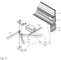
- FIG. 12 is an enlarged view of part E in FIG. 3
- FIG. 13 is a partially exploded view of FIG. 12
- FIG. 14 is an enlarged view of part F in FIG. 3 .
- the first pole 220 may include: the first horizontal rod 221 having a first vertical rod accommodation groove 221b therein and having one end connected to the first bracket 210 so as to be rotatable in a horizontal direction; the first vertical rod 222 connected to the other end of the first horizontal rod 221 so as to be rotatable in a vertical direction and having a first auxiliary vertical rod accommodation groove 222b therein, the first vertical rod 222 being configured to rotate to be accommodated in the first vertical rod accommodation groove 221b or exposed to the outside of the first horizontal rod 221; and the first auxiliary vertical rod 223 slidably connected to the first vertical rod 222 and configured to slide such that a length of the first auxiliary vertical rod 223 accommodated in the first auxiliary vertical rod accommodation groove 222b is adjusted.
- the first horizontal rod 221 may be rotatably connected to the first bracket 210 and rotate in the horizontal direction.
- the horizontal direction may mean a direction in which the first horizontal rod 221 rotates in parallel with a x-y plane based on FIG. 1 .
- the first vertical rod 222 may be provided at the other end of the first horizontal rod 221 so as to be rotatable in the vertical direction. To this end, a hinge part 222a may be formed at an end of the first vertical rod 222. In the stored mode, the first vertical rod 222 may rotate upward to be accommodated in the first vertical rod accommodation groove 221b.
- the first auxiliary vertical rod 223 may be slidably provided on the first vertical rod 222.
- the first auxiliary vertical rod 223 may slide in a longitudinal direction of the first vertical rod 222 in a state in which at least a part of the first auxiliary vertical rod 223 is inserted into the first auxiliary vertical rod accommodation groove 222b of the first vertical rod 222.
- the first auxiliary vertical rod 223 may include a fixing dial 223a.
- the fixing dial 223a may rotate in one direction to bind the first auxiliary vertical rod 223 to the first vertical rod 222 or rotate in the other direction to allow the first auxiliary vertical rod 223 to be slidable.
- the second pole 310 may include: the second horizontal rod 311 having a second vertical rod accommodation groove therein and having one end rotatably connected to the second bracket 350; the second vertical rod 312 connected to the other end of the second horizontal rod 311 so as to be rotatable in the vertical direction and having a second auxiliary vertical rod accommodation groove therein, the second vertical rod 312 being configured to rotate to be accommodated in the second vertical rod accommodation groove or exposed to the outside of the second horizontal rod 311; and the second auxiliary vertical rod 313 slidably connected to the second vertical rod 312 and configured to slide such that a length of the second auxiliary vertical rod 313 accommodated in the second auxiliary vertical rod accommodation groove is adjusted.
- the second pole 310 included in the second pole assembly 300 may have the same structure as the first pole 220. Therefore, the repetitive descriptions of the identical configurations will be omitted, and the descriptions of the identical configurations will be replaced with the above-mentioned description.
- the awning 1 for a vehicle includes the housing 100 having a thin column shape, which makes it possible to minimize a volume occupied when the awning 1 is loaded onto the vehicle.
- first pole 220 and the second pole 310 are rotatably provided, and the rotation axes of the first and second poles 220 and 310 are spaced apart from each other at a predetermined distance in the width direction of the housing, such that the first pole 220 and the second pole 310 may rotate without interfering with each other, which makes it possible to improve spatial utilization.
- FIGS. 15 to 36 an awning for a vehicle according to another embodiment of the present disclosure will be described with reference to FIGS. 15 to 36 .
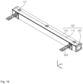
- FIG. 15 is a schematic perspective view of the awning for a vehicle according to the embodiment of the present disclosure
- FIG. 16 is a schematic perspective view of the awning for a vehicle when viewed at an angle different from an angle in FIG. 15
- FIG. 17 is a schematic perspective view illustrating a state in which a bracket module is separated from the awning for a vehicle in FIG. 15
- FIG. 18 is a schematic perspective view illustrating a state in which the awning for a vehicle in FIG. 15 is unfolded
- FIG. 19 is a schematic bottom perspective view of the awning illustrated in FIG. 18 .
- an awning 1' for a vehicle may include a housing 100 including an openable/closable internal space S (see FIG. 23 ), a first pole assembly 200 rotatably coupled to one side of the housing 100, a second pole assembly 300 rotatably coupled to the other side of the housing 100, a sun shelter 400 configured to cover an upper surface of the first pole assembly 200 and an upper surface of the second pole assembly, and bracket modules 500 detachably provided on one surface of the housing 100 and configured to fix the housing 100 to a fixing object R (see FIG. 36 ) such as a roof rack of a vehicle.
- a fixing object R see FIG. 36
- the awning 1' for a vehicle may have a stored mode (see FIG. 15 ) and an unfolded mode (see FIG. 19 ).
- the stored mode may mean a state in which the first pole assembly 200, the second pole assembly 300, and the sun shelter 400 are accommodated in the housing 100.
- the unfolded mode may mean a state in which the first pole assembly 200, the second pole assembly 300, and the sun shelter 400 are unfolded and exposed to the outside of the housing 100.
- the housing 100 may be manufactured by using a material such as metal or resin having predetermined rigidity and have a column shape including the internal space S.
- the housing 100 may be made of aluminum and have a quadrangular column shape.
- the housing 100 may include: a body 110 including the internal space S and having one surface to which the bracket modules 500 installed on the fixing object such as the roof of the vehicle are connected; a first door 120 rotatably coupled to an upper end of the body 110; and second doors 130 rotatably coupled to two opposite ends of the body 110.
- the internal space of the body 110 may be exposed to the outside or closed as the first door 120 and the second door 130 rotate.
- the body 110 may include the internal space S.
- the first pole assembly 200, the second pole assembly 300, and the sun shelter 400 may be accommodated in the internal space S of the body 110.
- the body 110 may be provided as a structure having a longitudinal cross-section having a ' ' shape.
- a longitudinal direction may mean an x-axis direction based on FIG. 15
- a width direction may mean a y-axis direction based on FIG. 15
- a thickness direction may mean a z-axis direction based on FIG. 15 .
- the first door 120 may be rotatably connected to an upper end of the body 110. One end of the first door 120 may be coupled to the body 110 by means of hinges 121. In case that the first door 120 is coupled to the body 110, the body 110 and the first door 120 may define the column shape having the internal space S and opened overall at two opposite ends thereof. The first door 120 may open or close a front side of the body 110.
- the second doors 130 may be rotatably connected to the two opposite ends of the body 110.
- the second doors 130 may selectively open or close the two opposite surfaces of the body 110.
- the one or more bracket modules 500 may be connected to one surface of the body 110.
- a bracket guide slit 111b may be formed in one surface of the body 110.
- the bracket module 500 may be coupled to one surface of the body 110 while sliding along the bracket guide slit 111b, and may be then coupled to a predetermined position.
- a seating protrusion 111a (see FIG. 34 ) may be provided at a lower end of one surface of the body 110 and seated on and caught by the bracket module 500. A detailed configuration of the bracket module 500 will be described below.
- the first pole assembly 200 may be rotatably provided at one side of the housing 100.
- the first pole assembly 200 may rotate to be accommodated in the internal space S of the housing 100 (stored mode) or exposed to the outside of the housing 100 (unfolded mode).
- the first pole assembly 200 may include a first pole 220.
- the first pole 220 may include a first horizontal rod 221, a first vertical rod 222 rotatably connected to an end of the first horizontal rod 221, and a first auxiliary vertical rod 223 slidably connected to the first vertical rod 222.
- the first vertical rod 222 may rotate to be inserted into the first horizontal rod 221.
- the first auxiliary vertical rod 223 may slide to be inserted into the first vertical rod 222.
- the second pole assembly 300 may be rotatably provided at the other side of the housing 100.
- the second pole assembly 300 may rotate to be accommodated in the internal space S of the housing 100 (stored mode) or exposed to the outside of the housing 100 (unfolded mode).
- the second pole assembly 300 may include a second pole 310.
- the second pole 310 may be similar in structure to the first pole 220.
- the second pole 310 may include a second horizontal rod 311, a second vertical rod 312 rotatably connected to an end of the second horizontal rod 311, and a second auxiliary vertical rod 313 slidably connected to the second vertical rod 312.
- the second vertical rod 312 may rotate to be inserted into the second horizontal rod 311.
- the second auxiliary vertical rod 313 may slide to be inserted into the second vertical rod 312.
- FIG. 20 is an enlarged view of part A in FIG. 15 .
- the other end of the first door 120 may be detachably fastened to a bottom surface of the body 110.
- An opening/closing device 112 may be provided on the first door 120 and the body 110.
- a hook device 112a may be provided on the first door 120
- a catching device 112b may be provided on the bottom surface of the body 110.
- the first door 120 may open or close the internal space S of the body 110 as the hook device 112a is fastened to the catching device 112b by being caught by the catching device 112b or separated from the catching device 112b.
- the configuration of the catching device and the configuration of the hook device may be substituted with various configurations commonly used in the art as long as the configuration of the catching device and the configuration of the hook device provide the structure capable of fastening the first door 120 to the body 110 so that the first door 120 is detachable.
- FIG. 21 is an enlarged view of part B in FIG. 15
- FIG. 22 is an enlarged view of part C in FIG. 18
- FIG. 23 is a side view of FIG. 22 .
- the second doors 130 may be rotatably connected to the two opposite ends of the body 110.
- the second doors 130 may be configured to open or close the two opposite ends of the housing 100.
- the second doors 130 may be rotatably connected to the bottom surfaces at the two opposite ends of the body 110.
- Fastening protrusions 131 may be provided on an outer peripheral surface of the second door 130. The fastening protrusions 131 may be inserted into or separated from first fastening holes 110a provided at the two opposite ends of the body 110 and second fastening holes 120a provided at the two opposite ends of the first door 120.
- the second doors 130 may close lateral sides of the housing 100 in the state in which the fastening protrusions 131 are inserted into the first fastening holes 110a and the second fastening holes 120a.
- the fastening protrusions 131 may be separated from the first fastening holes 110a and the second fastening holes 120a, and the second door 130 may rotate downward. That is, in the unfolded mode, the first door 120 may rotate upward to open the front side of the housing 100, and the second door 130 may rotate downward to open the lateral sides of the housing 100.
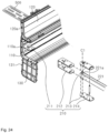
- FIG. 24 is a partially exploded view of FIG. 22 .
- the first pole assembly 200 may include a first bracket 210 fixedly installed on an inner surface of the housing 100, and the first pole 220 rotatably connected to the first bracket 210 and configured to rotate to be accommodated in the housing 100 or exposed to the outside of the housing 100.
- the first bracket 210 may be configured to support the first pole 220 and fix the first pole 220 to the inner surface of the housing 100, more specifically, to an inner surface of the body 110.
- the first bracket 210 may include a first fixing piece 211 coupled to the inner surface of the body 110, a first bracket outer casing 212 seated on and coupled to an upper surface of the first fixing piece 211, first bracket inner casings 213 coupled to an upper inner surface and a lower inner surface of the first bracket outer casing 212, and a first stopper 214 configured to restrict a rotation angle of the first pole 220.
- An end of the first horizontal rod 221 of the first pole 220 may be rotatably connected to the first bracket 210 by means of a first rotary hinge 221a.
- the first horizontal rod 221 may rotate by means of the first rotary hinge 221a.
- a rotation radius of the first horizontal rod 221 may be adjusted by the first stopper 214.
- the first horizontal rod 221 may rotate until the first horizontal rod 221 comes into contact with the first stopper 214.
- the rotation of the first horizontal rod 221 may be restricted after the first horizontal rod 221 comes into contact with the first stopper 214.
- FIG. 25 is an enlarged view of part D in FIG. 19
- FIG. 26 is a partially exploded view of FIG. 25
- FIG. 27 is a partial perspective view illustrating a state in which the first door is removed from the awning for a vehicle in FIG. 15 .
- the second pole assembly 300 may include a second bracket 350 fixedly installed on the inner surface of the housing 100, and one or more second poles 310, 320, and 330 rotatably connected to the second bracket 350 and configured to rotate to be accommodated in the housing 100 or exposed to the outside of the housing 100.
- the plurality of second poles 310, 320, and 330 may have the same structure.
- the plurality of second poles 310, 320, and 330 may have the same structure, but overall lengths of the plurality of second poles 310, 320, and 330 may be equal to or different from one another.
- the second bracket 350 may be configured to support the second pole 310 and fix the second pole 310 to the inner surface of the housing 100, more specifically, to the inner surface of the body 110.
- the second bracket 350 may include a second fixing piece 351 coupled to the inner surface of the body 110, a second bracket outer casing 352 seated on and coupled to an upper surface of the second fixing piece 351, and second bracket inner casings 353 coupled to an upper inner surface and a lower inner surface of the second bracket outer casing 352.
- the second pole 310 may be rotatably connected to the second bracket 350.
- the second pole 310 may be rotatably connected to the second bracket 350 by means of a second rotary hinge 310a.
- the second rotary hinge may also be provided as a plurality of second rotary hinges 310a, 320a, and 330a, and the plurality of second rotary hinges 310a, 320a, and 330a may respectively have inherent rotation axes C2, C3, and C4.
- the rotation axes C2, C3, and C4 may be disposed in parallel with one another and spaced apart from one another at predetermined distances in a width direction of the housing 100.
- the rotation axes C2, C3, and C4 are disposed to be spaced apart from one another at predetermined distances in the width direction as described above, the plurality of second poles 310, 320, and 330 may be accommodated in the housing 100 without interfering with one another in the stored mode.
- rotation axes C2, C3, and C4 of the second rotary hinges 310a, 320a, and 330a may also be disposed in parallel with a rotation axis C1 of the first rotary hinge 221a of the first pole 220 and spaced apart from the rotation axis C1 at predetermined distances in the width direction of the housing 100.
- the first pole 220 and the second pole 310 when the first pole 220 and the second pole 310 are accommodated in the housing 100, the first pole 220 and the second pole 310 may be accommodated side by side in the housing 100 without interfering with each other.
- an auxiliary pole 340 may be rotatably provided on at least one of the plurality of second poles 310, 320, and 330.
- the auxiliary pole 340 may be rotatably and hingedly coupled to the second pole 330 disposed at an outermost side among the plurality of second poles 310, 320, and 330.
- FIG. 28 is an enlarged view of part E in FIG. 19
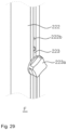
- FIG. 29 is a partially exploded view of FIG. 28
- FIG. 30 is an enlarged view of part F in FIG. 19 .
- the first pole 220 may include: the first horizontal rod 221 having a first vertical rod accommodation groove 221b therein and having one end connected to the first bracket 210 so as to be rotatable in a horizontal direction; the first vertical rod 222 connected to the other end of the first horizontal rod 221 so as to be rotatable in a vertical direction and having a first auxiliary vertical rod accommodation groove 222b therein, the first vertical rod 222 being configured to rotate to be accommodated in the first vertical rod accommodation groove 221b or exposed to the outside of the first horizontal rod 221; and the first auxiliary vertical rod 223 slidably connected to the first vertical rod 222 and configured to slide such that a length of the first auxiliary vertical rod 223 accommodated in the first auxiliary vertical rod accommodation groove 222b is adjusted.
- the first horizontal rod 221 may be rotatably connected to the first bracket 210 and rotate in the horizontal direction.
- the horizontal direction may mean a direction in which the first horizontal rod 221 rotates in parallel with a x-y plane based on FIG. 15 .
- the first vertical rod 222 may be provided at the other end of the first horizontal rod 221 so as to be rotatable in the vertical direction. To this end, a hinge part 222a may be formed at an end of the first vertical rod 222. In the stored mode, the first vertical rod 222 may rotate upward to be accommodated in the first vertical rod accommodation groove 221b.
- the first auxiliary vertical rod 223 may be slidably provided on the first vertical rod 222.
- the first auxiliary vertical rod 223 may slide in a longitudinal direction of the first vertical rod 222 in a state in which at least a part of the first auxiliary vertical rod 223 is inserted into the first auxiliary vertical rod accommodation groove 222b of the first vertical rod 222.
- the first auxiliary vertical rod 223 may include a fixing dial 223a.
- the fixing dial 223a may rotate in one direction to bind the first auxiliary vertical rod 223 to the first vertical rod 222 or rotate in the other direction to allow the first auxiliary vertical rod 223 to be slidable.
- the second pole 310 may include: the second horizontal rod 311 having a second vertical rod accommodation groove therein and having one end rotatably connected to the second bracket 350; the second vertical rod 312 connected to the other end of the second horizontal rod 311 so as to be rotatable in the vertical direction and having a second auxiliary vertical rod accommodation groove therein, the second vertical rod 312 being configured to rotate to be accommodated in the second vertical rod accommodation groove or exposed to the outside of the second horizontal rod 311; and the second auxiliary vertical rod 313 slidably connected to the second vertical rod 312 and configured to slide such that a length of the second auxiliary vertical rod 313 accommodated in the second auxiliary vertical rod accommodation groove is adjusted.
- the second pole 310 included in the second pole assembly 300 may have the same structure as the first pole 220. Therefore, the repetitive descriptions of the identical configurations will be omitted, and the descriptions of the identical configurations will be replaced with the above-mentioned description.
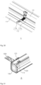
- FIG. 31 is a schematic exploded perspective view of the bracket module in FIG. 15
- FIG. 32 is a schematic exploded side view of the bracket module in FIG. 15
- FIG. 33 is a schematic side view illustrating a state in which the housing and the bracket module are separated in the awning for a vehicle in FIG. 15
- FIG. 34 is a schematic cross-sectional view actual G-G' in FIG. 15 .
- the bracket module 500 may be provided on one surface of the housing 100.
- the bracket module 500 may connect the housing 100 to the fixing object such as the roof rack of the vehicle.
- the bracket module 500 may include: a first fixing bracket 510 slidably inserted into one surface of the housing 100 and fixed to a predetermined position; a second fixing bracket 520 including a first fixing part 521 detachably fixed to one surface of the first fixing bracket 510 and a first bent part 522 bent and extending from one end of the first fixing part 521 and detachably fastened to the fixing object; and a third fixing bracket 530 including a second fixing part 531 detachably coupled to one surface of the first fixing bracket 510 and a second bent part 532 bent and extending from one end of the second fixing part 531 and configured to come into contact with one surface of the first bent part 522.
- the first fixing bracket 510 may be coupled to the housing 100, more specifically, to one surface of the body 110 while sliding, and may be fixed to a predetermined position after sliding and being coupled.
- the bracket guide slit 111b may be provided in one surface of the body 110.
- the first fixing bracket 510 may be fixed to one surface of the body 110 by means of fastening means 540.
- the fastening means 540 may include a bolt 541 and a nut 542. A head of the bolt 541 may be inserted into the bracket guide slit 111b of the housing 100 and slide. When the bolt 541 moves along the bracket guide slit 111b and reaches a predetermined position, the bolt 541 and the nut 542 may be fastened, such that the first fixing bracket 510 may be fixed to the housing 100.
- the fastening means 540 may be connected to an upper end of the first fixing bracket 510.
- first insertion grooves 513 may be formed at the upper end of the first fixing bracket 510, and the fastening means 540 may penetrate the first insertion grooves 513 and be connected to the housing 100. In this case, one end of the first insertion groove 513 may be opened.
- the first fixing bracket 510 may include at least one spacer 511.
- the spacer 511 may protrude from one surface of the first fixing bracket 510.
- a fastening means arrangement space may be defined between the housing 100 and one surface of the first fixing bracket 510 by the spacer 511.
- the spacer 511 may be formed by attaching a separate structure to the first fixing bracket 510, causing a part of the first fixing bracket 510 to protrude (see 511a), or bending a part of the first fixing bracket 510 (see 511b).
- a housing support rail 512 may protrude from a lower end of one surface of the first fixing bracket 510 that faces the housing 100, and the seating protrusion 111a of the housing 100 may be seated on and caught by the housing support rail 512.
- the housing support rail 512 may include a groove 512a into which the seating protrusion 111a is inserted.
- the second fixing bracket 520 may be a member connected to the fixing object and include the first fixing part 521 detachably fixed to one surface of the first fixing bracket 510, and the first bent part 522 bent and extending from one end of the first fixing part 521 and detachably fastened to the fixing object. Therefore, the second fixing bracket 520 may have a ' ' shape as a whole.
- the first bent part 522 may have a relatively longer length than the first fixing part 521 so that the first bent part 522 is easily fastened to the fixing object.
- the second fixing bracket 520 may include a rigidity reinforcing support 523.
- the rigidity reinforcing support 523 may press the first fixing part 521 and the first bent part 522, thereby preventing the first fixing part 521 and the first bent part 522 from being bent by an external force.
- the rigidity reinforcing support 523 may be inserted into and coupled to at least one of the first fixing part 521 and the first bent part 522.
- the rigidity reinforcing support 523 may be inserted into and coupled to a rigidity reinforcing support insertion groove 521a formed in the first fixing part 521.
- third insertion grooves 521b may be formed at one end of the first fixing part 521 which is not connected to the first bent part 522, and the third insertion grooves 521b may correspond to the first insertion grooves 513.
- One end of the third insertion groove 521b may be opened.
- the fastening means 540 may be penetratively coupled to the third insertion groove 521b and the first insertion groove 513.
- the third fixing bracket 530 may include: the second fixing part 531 detachably coupled to one surface of the first fixing bracket 510; and the second bent part 532 bent and extending from one end of the second fixing part 531 and configured to come into contact with one surface of the first bent part 522.
- the third fixing bracket 530 may have a ' ' shape as a whole.
- Second insertion grooves 531a may be formed at one side of the second fixing part 531 of the third fixing bracket 530 and have shapes corresponding to the first insertion grooves 513.
- the fastening means 540 may penetrate the first insertion groove 513 and the second insertion groove 531a and be connected to the housing 100.
- first fixing bracket 510 and the second fixing bracket 520 may be coupled after the rigidity reinforcing support 523 is coupled to the second fixing bracket 520.
- the rigidity reinforcing support 523 may be coupled to the second fixing bracket 520 after the first fixing bracket 510 and the second fixing bracket 520 are coupled.
- the step of fixing the second fixing bracket 520 to the roof rack of the vehicle may be performed by using the fastening means such as screws or the like.
- the fastening means 540 may be inserted into the bracket guide slit 111b of the housing 100.
- the head of the bolt 541 of the fastening means 540 may be coupled to the bracket guide slit 111b while sliding.
- the bolt 541 may slide along the bracket guide slit 111b to a predetermined position at which the bracket module 500 needs to be coupled.
- the seating protrusion 111a of the housing 100 may be inserted into the housing support rail 512 of the first fixing bracket 510.
- the third fixing bracket 530 may be disposed to adjoin one surface of the first fixing bracket 510 and an upper surface of the second fixing bracket 520.
- the bolt 541 may be disposed to penetrate the first insertion groove 513 and the second insertion groove 531a.
- the first fixing bracket 510 may be coupled to the housing 100 by fastening the nut 542 to the bolt 541.
- the second fixing bracket 520 may be coupled to the roof rack by completely fastening the fastening means of the second fixing bracket 520 that is temporarily fixed to the roof rack.
- the mode of the awning 1' for a vehicle may be switched to the unfolded mode.
- the first door 120 and the second doors 130 may be opened, and then the first pole assembly 200 and the second pole assembly 300 may be unfolded.
- the first horizontal rod 221 of the first pole assembly 200 may be rotated in the horizontal direction, and then the first vertical rod 222 may be rotated downward. Next, the first auxiliary vertical rod 223 may be slid to be fixed to the ground surface.
- the second horizontal rod 311 of the second pole assembly 300 may be rotated in the horizontal direction, and then the second vertical rod 312 may be rotated downward.
- the second auxiliary vertical rod 313 may be slid to be fixed to the ground surface.
- the first pole assembly 200 and the second pole assembly 300 are unfolded, such that the sun shelter 400 may be unfolded to the outside of the housing 100.
- the sun shelter 400 may further include an auxiliary sun shelter 410.
- One side of the auxiliary sun shelter 410 may be connected to the first pole assembly 200 or the second pole assembly 300, and the other side of the auxiliary sun shelter 410 may be provided as a free end.
- a user may connect the free end of the auxiliary sun shelter 410 to a hood part of the vehicle or other portions where the free end of the auxiliary sun shelter 410 may be fixed. Then, the user may fix the auxiliary sun shelter 410 to the roof rack by using a separate rope 410 or the like.
- the awning 1' for a vehicle may include the bracket module 500 having a simple structure, such that the awning 1' for a vehicle may be easily coupled to or separated from the fixing object such as the roof rack of the vehicle.
- the awning 1' for a vehicle may include the housing 100 having a thin column shape, which makes it possible to minimize a volume occupied when the awning 1 is loaded onto the vehicle.
- the first pole 220 and the second pole 310 may be rotatably provided, but the rotation axes of the first and second poles 220 and 310 may be spaced apart from each other at a predetermined distance in the width direction of the housing, such that the first pole 220 and the second pole 310 may rotate without interfering with each other, which makes it possible to improve spatial utilization.
Landscapes
- Engineering & Computer Science (AREA)
- Architecture (AREA)
- Civil Engineering (AREA)
- Structural Engineering (AREA)
- Tents Or Canopies (AREA)
- Soil Working Implements (AREA)
Applications Claiming Priority (4)
| Application Number | Priority Date | Filing Date | Title |
|---|---|---|---|
| KR1020210054833 | 2021-04-28 | ||
| KR1020210152926A KR20220148073A (ko) | 2021-04-28 | 2021-11-09 | 차량용 어닝 |
| KR1020210152925A KR20220148072A (ko) | 2021-04-28 | 2021-11-09 | 차량용 어닝 |
| PCT/KR2022/005486 WO2022231185A1 (fr) | 2021-04-28 | 2022-04-15 | Auvent pour véhicule |
Publications (1)
| Publication Number | Publication Date |
|---|---|
| EP4144939A1 true EP4144939A1 (fr) | 2023-03-08 |
Family
ID=83848212
Family Applications (1)
| Application Number | Title | Priority Date | Filing Date |
|---|---|---|---|
| EP22796019.2A Withdrawn EP4144939A1 (fr) | 2021-04-28 | 2022-04-15 | Auvent pour véhicule |
Country Status (8)
| Country | Link |
|---|---|
| US (1) | US20250075524A1 (fr) |
| EP (1) | EP4144939A1 (fr) |
| JP (1) | JP2023529318A (fr) |
| AU (1) | AU2022265354A1 (fr) |
| CA (1) | CA3180036A1 (fr) |
| DE (1) | DE212022000073U1 (fr) |
| WO (1) | WO2022231185A1 (fr) |
| ZA (1) | ZA202212851B (fr) |
Families Citing this family (4)
| Publication number | Priority date | Publication date | Assignee | Title |
|---|---|---|---|---|
| USD1093532S1 (en) * | 2022-09-16 | 2025-09-16 | Lonman Auto Accessories Co., Ltd | Car awning tent |
| US12296789B2 (en) * | 2022-12-12 | 2025-05-13 | Rivian Ip Holdings, Llc | Multi-purpose vehicle tonneau cover |
| USD1102625S1 (en) * | 2023-04-08 | 2025-11-18 | Lonman Auto Accessories Co., Ltd. | Vehicle awning arm |
| CN117400836A (zh) * | 2023-11-14 | 2024-01-16 | 秋野地(厦门)户外装备科技有限公司 | 一种升降车载行李架 |
Family Cites Families (20)
| Publication number | Priority date | Publication date | Assignee | Title |
|---|---|---|---|---|
| US3730196A (en) * | 1971-07-16 | 1973-05-01 | C Borskey | Storable vehicle canopy |
| US3949960A (en) * | 1975-03-24 | 1976-04-13 | The Scott & Fetzer Company | Bracket system for mounting retractable awnings |
| BE885600A (nl) * | 1979-11-09 | 1981-04-09 | Brutsaert Louis | Voortenkonstruktie |
| DE572741T1 (de) * | 1992-06-03 | 1994-12-22 | Carlo Maurizio Pozzi | Aufrollbare Markise von geringem Gewicht. |
| JP2983131B2 (ja) * | 1993-10-01 | 1999-11-29 | ワイケイケイ株式会社 | 自動車用日除け装置 |
| US5622214A (en) * | 1993-11-29 | 1997-04-22 | The Dometic Corporation | Awning assembly with stowable support arms |
| JP3308379B2 (ja) * | 1994-03-03 | 2002-07-29 | ワイケイケイ株式会社 | 自動車用日除け取付具 |
| JP3031830B2 (ja) * | 1994-11-18 | 2000-04-10 | 日産アルティア株式会社 | 車両用アタッチメントの取付け構造 |
| JP2007076409A (ja) * | 2005-09-12 | 2007-03-29 | Os Kogyo Kk | オーニング装置 |
| US20070113879A1 (en) * | 2005-11-21 | 2007-05-24 | Wei-Chiang Li | Car awning |
| GB2480483B (en) * | 2010-05-20 | 2017-05-24 | Belron Hungary Kft - Zug Branch | Deployable shelter structure |
| US20160251872A1 (en) * | 2015-02-27 | 2016-09-01 | Rex Tucker | Pickup Truck Bed Shelter System |
| DE202015104513U1 (de) * | 2015-08-26 | 2016-12-01 | Fiamma S.P.A. | Fahrzeugmarkise |
| AU2017101059B4 (en) * | 2017-06-30 | 2017-12-07 | Rhino Rack Australia Pty Limited | Stowable awning |
| CN213953195U (zh) * | 2019-06-04 | 2021-08-13 | 爱国者露营装备控股私人有限公司 | 安装到车辆的多构造的、可展开的遮篷组件 |
| US11897431B2 (en) * | 2019-06-04 | 2024-02-13 | Holz Industries Pty Ltd | Roof rack coupler |
| KR102072952B1 (ko) * | 2019-09-27 | 2020-02-03 | 차재호 | 차량용 어닝 |
| CN211342055U (zh) * | 2019-12-10 | 2020-08-25 | 东莞龙迈汽车用品制造有限公司 | 一种折叠帐篷骨架及折叠帐篷 |
| US11761228B2 (en) * | 2021-04-27 | 2023-09-19 | Lonman Auto Accessories Co., Ltd | Fan-shaped tent skeleton and fan-shaped tent |
| CN217925205U (zh) * | 2022-08-11 | 2022-11-29 | 衢州益高户外用品有限公司 | 一种转动结构及帐篷组件 |
-
2022
- 2022-04-15 EP EP22796019.2A patent/EP4144939A1/fr not_active Withdrawn
- 2022-04-15 WO PCT/KR2022/005486 patent/WO2022231185A1/fr not_active Ceased
- 2022-04-15 JP JP2022572621A patent/JP2023529318A/ja active Pending
- 2022-04-15 DE DE212022000073.0U patent/DE212022000073U1/de not_active Expired - Lifetime
- 2022-04-15 US US17/999,643 patent/US20250075524A1/en not_active Abandoned
- 2022-04-15 AU AU2022265354A patent/AU2022265354A1/en not_active Abandoned
- 2022-04-15 CA CA3180036A patent/CA3180036A1/fr active Pending
- 2022-11-25 ZA ZA2022/12851A patent/ZA202212851B/en unknown
Also Published As
| Publication number | Publication date |
|---|---|
| US20250075524A1 (en) | 2025-03-06 |
| WO2022231185A1 (fr) | 2022-11-03 |
| ZA202212851B (en) | 2023-11-29 |
| DE212022000073U1 (de) | 2023-03-20 |
| JP2023529318A (ja) | 2023-07-10 |
| CA3180036A1 (fr) | 2022-11-03 |
| AU2022265354A1 (en) | 2023-01-05 |
Similar Documents
| Publication | Publication Date | Title |
|---|---|---|
| EP4144939A1 (fr) | Auvent pour véhicule | |
| US3768858A (en) | Truck box cover | |
| US5839462A (en) | Extensible and retractable canopy structure for vehicles and the like | |
| EP4194646A1 (fr) | Tente de toit | |
| US6003583A (en) | Door opening screening system | |
| US20240160252A1 (en) | Hinge | |
| CN112238825A (zh) | 滑动门线束 | |
| US11584208B2 (en) | Method of enhancing rain and sun protection using a rain and sun shield for golf carts | |
| RU147998U1 (ru) | Закрывающий узел для торца приборной панели | |
| US7290581B2 (en) | Half spread folding door | |
| KR20220148073A (ko) | 차량용 어닝 | |
| KR20220148072A (ko) | 차량용 어닝 | |
| CN220285446U (zh) | 车辆用遮篷 | |
| KR100589682B1 (ko) | 접이식 파라솔 | |
| KR102305742B1 (ko) | 차량 탈부착형 텐트 | |
| KR20250041595A (ko) | 루프탑 텐트 | |
| WO2022245044A1 (fr) | Tente de toit et procédé d'assemblage de tente de toit | |
| KR102368045B1 (ko) | 차량용 빌트인 어닝 캐리어 | |
| RU2690950C1 (ru) | Узел солнцезащитного козырька, имеющий несколько зеркал | |
| CN218623011U (zh) | 一种可调节遮阳角度曲臂遮阳篷 | |
| CN223787354U (zh) | 一种坐架防护结构 | |
| JP3072558U (ja) | 防風雨機構を備えた屋外用筐体 | |
| KR19980027959A (ko) | 차양막이 내장된 승합차용 루프랙구조 | |
| JP2003336432A (ja) | スライド式扉の開閉構造 | |
| KR0120908Y1 (ko) | 자동차의 후드 개폐용 안테나식 로드 |
Legal Events
| Date | Code | Title | Description |
|---|---|---|---|
| STAA | Information on the status of an ep patent application or granted ep patent |
Free format text: STATUS: THE INTERNATIONAL PUBLICATION HAS BEEN MADE |
|
| PUAI | Public reference made under article 153(3) epc to a published international application that has entered the european phase |
Free format text: ORIGINAL CODE: 0009012 |
|
| STAA | Information on the status of an ep patent application or granted ep patent |
Free format text: STATUS: REQUEST FOR EXAMINATION WAS MADE |
|
| 17P | Request for examination filed |
Effective date: 20221201 |
|
| AK | Designated contracting states |
Kind code of ref document: A1 Designated state(s): AL AT BE BG CH CY CZ DE DK EE ES FI FR GB GR HR HU IE IS IT LI LT LU LV MC MK MT NL NO PL PT RO RS SE SI SK SM TR |
|
| STAA | Information on the status of an ep patent application or granted ep patent |
Free format text: STATUS: THE APPLICATION HAS BEEN WITHDRAWN |
|
| 18W | Application withdrawn |
Effective date: 20240116 |