EP4144940A2 - Schloss - Google Patents
Schloss Download PDFInfo
- Publication number
- EP4144940A2 EP4144940A2 EP22185026.6A EP22185026A EP4144940A2 EP 4144940 A2 EP4144940 A2 EP 4144940A2 EP 22185026 A EP22185026 A EP 22185026A EP 4144940 A2 EP4144940 A2 EP 4144940A2
- Authority
- EP
- European Patent Office
- Prior art keywords
- bolt
- coupling
- lock
- locking
- state
- Prior art date
- Legal status (The legal status is an assumption and is not a legal conclusion. Google has not performed a legal analysis and makes no representation as to the accuracy of the status listed.)
- Granted
Links
Images


Classifications
-
- E—FIXED CONSTRUCTIONS
- E05—LOCKS; KEYS; WINDOW OR DOOR FITTINGS; SAFES
- E05B—LOCKS; ACCESSORIES THEREFOR; HANDCUFFS
- E05B1/00—Knobs or handles for wings; Knobs, handles, or press buttons for locks or latches on wings
- E05B1/0038—Sliding handles, e.g. push buttons
-
- B—PERFORMING OPERATIONS; TRANSPORTING
- B62—LAND VEHICLES FOR TRAVELLING OTHERWISE THAN ON RAILS
- B62H—CYCLE STANDS; SUPPORTS OR HOLDERS FOR PARKING OR STORING CYCLES; APPLIANCES PREVENTING OR INDICATING UNAUTHORIZED USE OR THEFT OF CYCLES; LOCKS INTEGRAL WITH CYCLES; DEVICES FOR LEARNING TO RIDE CYCLES
- B62H5/00—Appliances preventing or indicating unauthorised use or theft of cycles; Locks integral with cycles
- B62H5/001—Preventing theft of parts or accessories used on cycles, e.g. lamp, dynamo
-
- E—FIXED CONSTRUCTIONS
- E05—LOCKS; KEYS; WINDOW OR DOOR FITTINGS; SAFES
- E05B—LOCKS; ACCESSORIES THEREFOR; HANDCUFFS
- E05B47/00—Operating or controlling locks or other fastening devices by electric or magnetic means
- E05B47/0001—Operating or controlling locks or other fastening devices by electric or magnetic means with electric actuators; Constructional features thereof
-
- E—FIXED CONSTRUCTIONS
- E05—LOCKS; KEYS; WINDOW OR DOOR FITTINGS; SAFES
- E05B—LOCKS; ACCESSORIES THEREFOR; HANDCUFFS
- E05B47/00—Operating or controlling locks or other fastening devices by electric or magnetic means
- E05B47/06—Controlling mechanically-operated bolts by electro-magnetically-operated detents
- E05B47/0657—Controlling mechanically-operated bolts by electro-magnetically-operated detents by locking the handle, spindle, follower or the like
- E05B47/0661—Controlling mechanically-operated bolts by electro-magnetically-operated detents by locking the handle, spindle, follower or the like axially, i.e. with an axially engaging blocking element
-
- E—FIXED CONSTRUCTIONS
- E05—LOCKS; KEYS; WINDOW OR DOOR FITTINGS; SAFES
- E05B—LOCKS; ACCESSORIES THEREFOR; HANDCUFFS
- E05B47/00—Operating or controlling locks or other fastening devices by electric or magnetic means
- E05B47/06—Controlling mechanically-operated bolts by electro-magnetically-operated detents
- E05B47/0676—Controlling mechanically-operated bolts by electro-magnetically-operated detents by disconnecting the handle
- E05B47/068—Controlling mechanically-operated bolts by electro-magnetically-operated detents by disconnecting the handle axially, i.e. with an axially disengaging coupling element
-
- E—FIXED CONSTRUCTIONS
- E05—LOCKS; KEYS; WINDOW OR DOOR FITTINGS; SAFES
- E05B—LOCKS; ACCESSORIES THEREFOR; HANDCUFFS
- E05B55/00—Locks in which a sliding latch is used also as a locking bolt
- E05B55/06—Locks in which a sliding latch is used also as a locking bolt the handle being disconnected
-
- E—FIXED CONSTRUCTIONS
- E05—LOCKS; KEYS; WINDOW OR DOOR FITTINGS; SAFES
- E05B—LOCKS; ACCESSORIES THEREFOR; HANDCUFFS
- E05B55/00—Locks in which a sliding latch is used also as a locking bolt
- E05B55/12—Locks in which a sliding latch is used also as a locking bolt the bolt being secured by the operation of a hidden parallel member ; Automatic latch bolt deadlocking mechanisms, e.g. using a trigger or a feeler
-
- E—FIXED CONSTRUCTIONS
- E05—LOCKS; KEYS; WINDOW OR DOOR FITTINGS; SAFES
- E05B—LOCKS; ACCESSORIES THEREFOR; HANDCUFFS
- E05B71/00—Locks specially adapted for bicycles, other than padlocks
-
- E—FIXED CONSTRUCTIONS
- E05—LOCKS; KEYS; WINDOW OR DOOR FITTINGS; SAFES
- E05C—BOLTS OR FASTENING DEVICES FOR WINGS, SPECIALLY FOR DOORS OR WINDOWS
- E05C1/00—Fastening devices with bolts moving rectilinearly
- E05C1/08—Fastening devices with bolts moving rectilinearly with latching action
- E05C1/12—Fastening devices with bolts moving rectilinearly with latching action with operating handle or equivalent member moving otherwise than rigidly with the latch
-
- B—PERFORMING OPERATIONS; TRANSPORTING
- B62—LAND VEHICLES FOR TRAVELLING OTHERWISE THAN ON RAILS
- B62J—CYCLE SADDLES OR SEATS; AUXILIARY DEVICES OR ACCESSORIES SPECIALLY ADAPTED TO CYCLES AND NOT OTHERWISE PROVIDED FOR, e.g. ARTICLE CARRIERS OR CYCLE PROTECTORS
- B62J43/00—Arrangements of batteries
- B62J43/10—Arrangements of batteries for propulsion
- B62J43/13—Arrangements of batteries for propulsion on rider-propelled cycles with additional electric propulsion
-
- E—FIXED CONSTRUCTIONS
- E05—LOCKS; KEYS; WINDOW OR DOOR FITTINGS; SAFES
- E05B—LOCKS; ACCESSORIES THEREFOR; HANDCUFFS
- E05B47/00—Operating or controlling locks or other fastening devices by electric or magnetic means
- E05B47/0001—Operating or controlling locks or other fastening devices by electric or magnetic means with electric actuators; Constructional features thereof
- E05B2047/0014—Constructional features of actuators or power transmissions therefor
- E05B2047/0018—Details of actuator transmissions
- E05B2047/0026—Clutches, couplings or braking arrangements
-
- E—FIXED CONSTRUCTIONS
- E05—LOCKS; KEYS; WINDOW OR DOOR FITTINGS; SAFES
- E05B—LOCKS; ACCESSORIES THEREFOR; HANDCUFFS
- E05B47/00—Operating or controlling locks or other fastening devices by electric or magnetic means
- E05B2047/0048—Circuits, feeding, monitoring
- E05B2047/0067—Monitoring
- E05B2047/0069—Monitoring bolt position
Definitions
- the invention relates to a lock with a locking mechanism which has a bolt which can be moved between a locking position provided for securing a counterpart that can be moved relative to the locking mechanism and an unlocking position provided for releasing the counterpart.
- Such locks are known in principle and are used, for example, to secure an energy store on an electric bicycle or another electric vehicle, or to lock a transport box or a frame lock of the electric vehicle.
- the bolt of the lock is usually pushed into the locking position by a comparatively strong spring element, from which it can be moved into an unlocking position by means of an actuating element.
- strong vibrations e.g. when driving over bumpy terrain or when jumping, will cause the bolt to move unintentionally against the spring force of the spring element into the unlocking position, which could result in the loss of an energy store secured by the lock, for example.
- a strong acceleration is generated by acting on the actuating element with increased force, and movement of the bolt into the unlocked position can thus be forced.
- the invention is based on the object of creating a lock of the type described at the outset, which is characterized by increased security and a high degree of ease of use.
- the lock according to the invention has an actuating element for manually moving the bolt into the unlocked position.
- the lock includes a coupling element, which can be transferred between a coupling state, in which it is coupled to the bolt, and a decoupling state, in which it can be moved relative to the bolt, and which can be moved from a passive position to an active position by means of the actuating element.
- the bolt can be moved into the unlocked position by a movement from the passive position into the active position of the coupling element in the coupled state by the actuating element.
- the moveable counterpart of the lock can, for example, be an energy storage device or part of an energy storage device or a block of a frame lock or brake disc lock or a hasp or a pawl of a lock of a transport box of a vehicle or electric vehicle, in particular an electric bicycle.
- the lock can also be used in another vehicle or electric vehicle, in particular an electric wheelchair, electric scooter or electric kart, as well as in a human-powered vehicle.
- the lock according to the invention can also be provided for locking doors or windows, for example also of a caravan or mobile home, as well as for locking cupboard doors or drawers or transport crates or containers. In principle, any mechanical lock can be replaced by the lock according to the invention.
- the latch In its locking position, the latch can engage in a recess in the counterpart or engage behind it in order to prevent the counterpart from being removed from the locking mechanism.
- the bolt itself can have a recess into which one in the locking position corresponding structure of the counterpart or the energy store can intervene. If the lock is intended to secure an energy storage device, the bolt can engage in a recess in the energy storage device in its locking position or engage behind a projection of the energy storage device in such a way that the removal of the energy storage device is blocked.
- the invention provides that the actuating element does not act directly on the bolt in order to move it from the locking position to the unlocking position. Instead, the actuating element interacts with a coupling element, which can be transferred from a passive position into an active position by the actuating element.
- the coupling element In a coupling state, the coupling element is coupled to the bolt in such a way that a movement of the coupling element is transmitted to the bolt.
- a rigid coupling can be provided, so that the coupling element moves the bolt directly in the manner of a driver, in particular linearly, with a transfer of the coupling element from the passive position to the active position causing the bolt to move from the locked position to the unlocked position.
- the movement of the bolt into the locking position is brought about by the actuating element and a movement of the coupling element from the active position into the passive position.
- the coupling element In the decoupling state, the coupling element is decoupled from the bolt, so that the coupling element can move independently of a movement of the bolt, and vice versa.
- the actuating element and the coupling element can also be in engagement with one another in the decoupling state, so that actuation of the actuating element causes the coupling element to move from the passive state to the active state.
- the bolt is not taken into the unlocked position. An unlocking of Castle by the actuator is therefore only possible in the coupled state.
- a movement of the actuating element can be decoupled from a movement of the bolt into the unlocked position. In the uncoupled state, therefore, even vehement actuation or manipulation of the actuating element has no effect on the bolt, making unauthorized unlocking of the lock significantly more difficult and increasing the security of the lock.
- the actuating element can have a handle for keyless actuation, as a result of which a high level of operating convenience is achieved.
- the handle can include a push button, a slider or a pulling element for transmitting a linear, in particular pushing or pulling, actuating movement to the coupling element.
- the handle can include a rotary knob or rotary handle, which can be operated by a rotary actuation movement, or a lever.
- the bolt can be moved by the actuating element, in particular, only by manual actuation by a user, without an electric motor movement of the bolt being provided.
- the actuating element can comprise a lock cylinder and an associated key.
- the coupling element is arranged so that it can move parallel to the bolt.
- the coupling element and the bolt can have a common longitudinal axis, along which they are each arranged to be movable.
- the direction of movement of the actuating element can be oriented at least substantially perpendicularly to a direction of movement of the bolt and/or the coupling element. In order to transmit an actuation movement from the actuation element to the coupling element, these can each have corresponding transmission features.
- the actuating element and the coupling element can have control bevels that work together, by means of which an actuating movement of the actuating element is converted into a movement of the bolt oriented at least essentially perpendicular thereto.
- a link guide, a connecting rod, an articulated connection or another geared connection can also be provided.
- the bolt can have a guide section in which the coupling element is guided.
- the guide section can be designed as a recess in the bolt, for example as a guide shaft.
- the coupling element can be slidably guided in the guide section.
- the lock includes a control element for selectively transferring the coupling element into the coupling state or into the uncoupling state.
- the control element itself can be arranged to be movable.
- the transfer of the coupling element between the coupling state and the decoupling state can include a translational movement, in particular a linear movement, and/or a rotational movement of the control element.
- the bolt and the coupling element can be coupled by the control element in the coupling state.
- the control element In the coupling state, the control element can be in engagement with the bolt and the coupling element, at least in sections, so that they are coupled to one another.
- control element is designed as a control fork which encompasses the bolt on three sides.
- the locking bar can extend at least partially along its direction of movement through an encompassed area of the control fork defined by the control fork.
- control element can have at least one coupling bolt for coupling the bolt and the coupling element, in particular the longitudinal axis of which extends perpendicular to a movement direction of the bolt.
- the at least one coupling bolt can be designed in such a way that in the coupled state it can be brought into engagement with the bolt and the coupling element in a coupling manner and that in the uncoupled state it can be brought into engagement either only with the bolt or only with the coupling element or with neither of the two is in order not to couple them with each other.
- the coupling bolt can be movably arranged.
- the transition between the coupling state and the decoupling state can include a rotational and/or translational movement of the coupling bolt, in particular a linear movement of the coupling bolt along its longitudinal axis.
- Several coupling bolts can be provided.
- the coupling bolt can extend, at least in sections, perpendicularly to prong-like sections of the control fork.
- the coupling element and the bolt can each have at least one recess for receiving a coupling section of the control element, in particular for receiving a coupling bolt.
- the bolt and/or the coupling element can each have a plurality of recesses, into which sections of the control element engage simultaneously or only in the coupling state or only in the decoupling state.
- the control element and the latch can be movably connected to one another.
- a movable connection both in the Coupling state as well as in the decoupling state and exist regardless of the unlocked position or locked position of the bolt.
- the latch and control may be connectable to one another at more than one connection point.
- the bolt can be connected to the control element at least at one connection point at any time.
- a movement of the bolt from the locking position to the unlocking position can cause a rotational movement and/or a translational movement of the control element.
- the control element can be entrained by the bolt without itself being driven to rotate and/or translate.
- the control can be pivoted about a suspension point by the bolt.
- the lock has a locking element that can be adjusted between a locked position, in which the bolt is locked in its locking position, and a release position, in which the bolt can be moved into its unlocked position.
- the blocking element can be designed in particular as a pin or peg. In principle, the blocking element can interact with any movable element of the lock to block the bolt, but preferably with the bolt itself.
- the locking mechanism In the locked position, the locking mechanism directly secures the counterpart in the lock by means of the bolt, and the locking element also blocks the locking mechanism so that it can only be actuated after the locking element has been moved into the release position. In order to unlock the lock, a total of two release steps are therefore required.
- Accidental movement of the latch to the unlocked position, such as when driving over rough terrain or being subjected to force the lock are particularly effectively prevented by the locking element in the locked position, so that the security of the lock is increased.
- An adjustment of the blocking element between the blocking position and the release position can include a rotational and/or translational movement of the blocking element.
- the adjustment of the blocking element can include a pivoting, twisting, displacement of the blocking element or a combination thereof, in particular a linear movement along a longitudinal axis of the blocking element.
- the blocking element is formed on the control element.
- a longitudinal axis of the blocking element can be arranged parallel or coaxially with a longitudinal axis of the control element, in particular a coupling bolt.
- the control element can thus control both a transfer of the coupling element into the coupling state or decoupling state and an adjustment of the blocking element between the blocking position and the release position, with both processes being able to take place simultaneously.
- the blocking element when the coupling element is switched to the uncoupled state, the blocking element is switched to its blocking position, so that manual movement of the bolt by the actuating element is prevented and, in addition, the blocking element in the blocked position prevents accidental or violent movement of the Bolt is excluded in the unlocked position.
- the blocking element when the coupling element is transferred into the coupling state in which movement of the bolt by the actuating element is possible, the blocking element is also moved into its release position in order to enable the bolt to be moved into its unlocked position.
- the blocking element in its blocking position, is in engagement with a component of the lock, in particular with a non-moving component, such as a housing, of the lock.
- the component of the lock can be configured to prevent movement of the blocking element along the direction of movement of the bolt.
- a movable component of the lock can be provided to secure the blocking element in its blocking position.
- a corresponding receptacle for the blocking element can be provided on the movable or non-movable component of the lock, in particular on the housing of the lock, which mount blocks movement of the blocking element, in particular in the direction of movement of the bolt.
- the bolt can be moved from the locking position into the unlocking position against a restoring force of a spring.
- the coupling element can be brought from the passive position into the active position against the restoring force of a spring. This ensures that the locking bar is always pushed into its locking position in the coupled state and in the uncoupled state. This reduces the risk of the counterpart being accidentally released from the locking mechanism.
- a latch function can be implemented by the spring, which enables the counterpart, for example an energy store, to automatically engage in the locking mechanism, with the latch being automatically moved into the locking position by the spring after it has engaged.
- the bolt and the coupling element can be brought into the unlocked position or into the active position against the restoring force of the same spring. This ensures that the coupling element and the bolt are always correctly aligned relative to one another in the decoupling state and in particular in the passive position of the coupling element and in particular that the cutouts of the bolt and of the Coupling elements are aligned with one another, in particular aligned, that the control element can engage in the coupling state therein.
- the lock has at least one actuator for transferring the coupling element between the coupling state and the decoupling state.
- the lock has at least one actuator for adjusting the locking element between its locked position and its release position.
- the same actuator can be provided for transferring the coupling element and the blocking element, in particular with the transfer of the coupling element and the blocking element being able to take place simultaneously.
- the actuator can be an electromotive or electromagnetic actuator. A manual transfer of the blocking element into a blocking position or release position or the coupling element into a coupling state or uncoupling state by a user of the lock is therefore unnecessary, which increases the ease of use. Since only the blocking element and/or the coupling element are actuated by the actuator, but not the bolt, an actuator with lower power and/or more compact dimensions can be used.
- a keyless operation of the lock can include that after an electrical transfer of the coupling element in the coupling state and an electrical adjustment of the blocking element in the release position, a manual movement of the bolt can be done by means of the actuating element in the unlocked position.
- the lock can include at least one actuator, in particular an electromotive or electromagnetic actuator, for actuating the control element.
- the control element can be moved rotationally and/or translationally by the actuator, in particular pivoted or displaced, in order to effect a transfer of the coupling element and/or an adjustment of the blocking element.
- the lock can also comprise a detection means for detecting that the bolt has assumed the locking position.
- the detection means can be used to monitor whether the bolt actually reaches its locking position during a locking process or whether it is prevented from doing so, for example, by an energy store that has not been used correctly.
- a suitable warning can be output to the user, for example in the form of optical and/or acoustic feedback generated on an on-board computer of an electric bicycle, on the user's mobile phone and/or on the lock itself.
- the detection means can include, for example, an actuator, in particular an electric motor or electromagnetic actuator, for adjusting a locking element, which can be adjusted between a locked position, in which the bolt is locked in its locked position, and a release position, in which the bolt can be moved into its unlocked position .
- the actuator can be the same actuator that is also provided for moving the control element.
- a lock 10 in particular for an electric bicycle and, for example, for securing an energy store on the electric bicycle, is shown.
- the lock can also be used to lock doors, windows, drawers, transport crates, containers or generally as a replacement for a mechanical lock.
- the lock 10 comprises a locking mechanism with a bolt 12 which has a locking section 12.1.
- the bolt 12 is between an in 1 locking position and unlocking position shown movable ( 15 ). In the locking position, the locking portion 12.1 of the bolt 12 can be moved relative to the locking mechanism with a counterpart, for example the energy accumulator (not shown), to secure it in the lock 10, the unlocking position being for the release of the counterpart.
- the lock 10 To move the bolt from the locked position to the unlocked position, the lock 10 includes a manually operable actuating element 14, which includes a handle 16 in the form of a push button in the embodiment shown.
- actuating element 14 When the push button is actuated, the actuating element 14 is displaced along an actuating axis B in the direction of the bolt.
- the actuating element 14 does not act directly on the bolt 12 in order to move it into the unlocked position. Instead, a coupling element 18 is provided, which engages with the actuating element 14 ( 8 ) and through this from a passive position as in 1 is shown (cf. also 8 ), to an active position, as in 14, 15 shown is movable.
- the coupling element 18 is arranged to be movable parallel to the bolt 12 .
- the bolt 12 and the coupling element 18 have a common longitudinal axis L ( 10 ), which also defines the direction of movement of bolt 12 and coupling element 18.
- the coupling element 18 is guided in a guide section 20 formed by the bolt 12, which includes a guide shaft 21 which is formed centrally within the bolt 12 and in which the coupling element 18 is slidably mounted.
- the guide shaft 21 has a lateral width S, which corresponds approximately to a lateral extent D of the coupling element 18 ( 11A, 12 ).
- the longitudinal axis L of the bolt 12 and the coupling element 18 and thus their direction of movement is oriented perpendicular to the direction of movement of the actuating element 14 along the actuating axis B.
- the actuating element 14 has a transmission section 22, which has a first oblique control surface 24 .
- the coupling element 18 has a second inclined control surface 26 along which the first inclined control surface 24 of the actuating element 14 can be moved in a sliding manner in the direction of the actuating axis B ( 8 ).
- the coupling element 18 is movably mounted by means of a spring 28 and, when the actuating element 14 is pressed in, is pushed into its active position by the first inclined control surface 24 against the restoring force of the spring 28 in the direction of its longitudinal axis L ( 14 ).
- the coupling element 18 has a bearing recess 30, in which the spring 28 designed as a spiral spring can engage. The coupling element 18 sits stably on the spring 28 ( 12 ).
- the bolt 12 is mounted by means of the same spring 28 so that it can be moved from its locked position into the unlocked position against the restoring force of the spring 28 .
- the bolt 12 At its end facing away from the locking section 12.1, the bolt 12 has an essentially annular bearing recess 34 for engaging the spring 28, with a stable seat of the bolt on the spring being ensured by two bearing tongues 36, which delimit the annular bearing recess 34 on the inside in sections ( 11A,B ).
- a latch function of the lock 10 can be implemented.
- a counterpart can be inserted into the locking mechanism, for example the energy store, when the bolt 12 is in the locked state, since the bolt 12 is temporarily pressed into its unlocked position when the counterpart is inserted against the restoring force of the spring 28 .
- a control bevel 12.2 is provided on the bolt. If the counterpart is fully inserted into the lock 10, the bolt 12 is automatically pushed into its locking position by the spring 28, so that the counterpart is protected against loss immediately.
- the coupling element 18 is in a decoupling state, in which it is arranged to be movable relative to the bolt 12, so that a movement of the actuating element 14 and a movement of the coupling element 18 generated thereby from the passive position into the active position has no effect on the bolt 12 ( 14 ).
- the coupling element 18 can be transferred into a coupling state in which it is coupled to the bolt 12 .
- the coupling state when the actuating element 14 is actuated, the coupling element 18 is transferred into the active position and the bolt 12 coupled to the coupling element 18 is taken along into its unlocked position ( 15 ).
- a control element 38 is provided ( 13A,B ).
- the control element 38 is designed as a control fork 40 which, in addition to a suspension strut 42, includes a first tine 44.1 and a second tine 44.2.
- the control fork 40 encompasses the bolt 12 on three sides, the surface 46 encompassed by the control fork 40 being oriented essentially perpendicular to the longitudinal axis L of the bolt when the bolt 12 is in the locked state or when the coupling element 18 is in the passive position.
- the control element 38 also has a coupling bolt 48, which extends between the first and second prongs 44.1, 44.2 and whose longitudinal axis K is oriented perpendicular to the prongs 44.1, 44.2 and to the direction of movement and longitudinal axis L of the bolt 12 and the coupling element 18 ( figure 10 , 13B ).
- the coupling bolt 48 is arranged on an end of the control fork 40 opposite the suspension strut 42 and hits the bolt 12 and the coupling element 18 ( 2 , 7 ).
- the coupling element 18 and the bolt 12 each have corresponding recesses.
- the coupling element 18 has a passage opening 52, the diameter of which allows the coupling bolt 48 to pass through in the axial direction ( figure 12 ).
- the bolt 12 has a first passage opening 54.1 and a second passage opening 54.2, which are arranged on opposite sides of the bolt 12 in relation to the longitudinal axis K of the coupling bolt 48.
- the joint mounting of the bolt 12 and the coupling element 18 by means of the spring 28 ensures that the passage openings 52, 54.1, 54.2 of the coupling element 18 and the bolt 12 are aligned with one another in the passive position.
- the coupling bolt 48 is designed in two parts and includes a first coupling bolt section 48.1 and a second coupling bolt section 48.2, which are separated by a gap 50.
- the gap 50 has approximately the lateral width S of the guide shaft 21 arranged in the bolt 12 .
- the coupling element 18 can therefore be arranged in the gap 50 in such a way that it does not engage with the coupling bolt 48 . This just characterizes the decoupling state according to Figures 1 to 9 and 14 and is in the sectional view through the coupling bolt 48 according to 9 shown.
- the coupling element 18 can therefore be moved relative to the control element 38 in the decoupling state by the actuating element 14 independently of the control element 38 ( 14 ).
- the lock 10 has an electric motor 56 which is connected to the control element 38 via the suspension strut 42.
- the suspension strut 42 has an articulated groove 58 which, in the exemplary embodiment shown, is articulated to a swivel arm 60 seated on a shaft 63 of the electric motor 56, with the swivel arm 60 being able to be swiveled into well-defined positions (arrow 65 in figure 5 ).
- one inside 14 shown first position of the pivot arm 60 corresponds to the decoupling state according to Figures 1 to 9 and one in 15 shown second position of the swivel arm 60 the coupling state of the coupling element 18.
- a pivoting of the pivot arm 60 from the first position according to 14 to the second position according to 15 leads to a linear displacement of the control element 38 along the longitudinal axis K of the coupling bolt 48, the direction 62 of the linear displacement in 9 indicated by an arrow 62.
- the linear displacement pushes the first coupling bolt section 48.1 out of the first passage opening 54.1 and thus disengages it from the bolt 12.
- the second coupling bolt section 54.2 is guided completely through the second passage opening 54.2 and into the passage opening 52 of the coupling element 18. In this way, the bolt 12 and the coupling element 18 are coupled to one another by the coupling bolt 48 and in particular by the second coupling bolt section 48.2 of the control element 38, ie the coupling element 18 is brought into its coupling state ( 15 ).
- the coupling element 18 is rigidly connected to the latch 12 with respect to the direction of movement along the longitudinal axis L of the coupling element 18, so that the latter is carried along by the coupling element 18 into its unlocking position when the actuating element 14 is actuated.
- the coupling bolt 48 is also carried along along the longitudinal axis L of the bolt 12, so that the control element 38 is rotated, with a longitudinal axis of the articulated channel 58 being tilted in the direction of the bolt 12 ( 15 ).
- the articulation groove 58 is bounded on two sides by rounded wall portions 64 between which a cam portion 66 of the pivot arm 60 is received.
- a translational movement of the control element 38 in the direction of the bolt 12, in particular parallel to the actuation axis B, can also be provided, which ensures that the bolt 12 with its passage openings 54.1 , 54.2, the coupling element 18 with its passage opening 52 and the coupling bolt 48 are always aligned with one another with respect to the actuation axis B.
- the coupling pin 48 of the control element 38 is thus effectively displaced parallel to the longitudinal axis L of the bolt.
- the wall sections 64 are designed in such a way that they offer reliable guidance of the control element 38 during the rotational movement and the translational movement.
- the latch 12 engages the control member 38 not only in the coupled state but also in the uncoupled state ( 9 ), wherein the bolt 12 and the control element 38 are movably connected to one another.
- the lock 10 also has a locking element 68, which is formed in the embodiment shown as a locking pin on the control element 38, the extends coaxially with the coupling bolt 48 from the second prong 44.2 to an outside of the control fork 40.
- the locking element 68 can be adjusted between a locking position, in which the bolt 12 is locked in its locked position by the locking element 68, and a release position, in which the bolt 12 can be moved into its unlocked position.
- the blocking element 68 can be engaged with a component of the lock 10 in its blocking position.
- an opening 72 is made in the housing wall 70 , which receives the blocking element 68 in its blocked state and blocks a movement of the blocking element 68 along the longitudinal axis L of the bolt 12 .
- blocking element 68 is formed on control element 38, which is always connected to bolt 12 by means of coupling bolt 48 and specifically by means of second coupling bolt section 48.2, which is coaxial with blocking element 68, the locking of blocking element 68 in the blocking position also causes a movement of the Bolt 12 blocked along its longitudinal axis L and thus moving into the unlocked position.
- the adjustment of the locking element 68 from the locked position according to 9 into the release position takes place by means of the electric motor 56.
- the control element 38 moves linearly along the direction 62 ( 9 )
- the blocking element 68 is released from the opening 72 of the housing wall 70 and thus a movement along the longitudinal axis L of the bolt 12 is made possible.
- the movement of the blocking element 68 into the release position is simultaneously accompanied by a transfer of the coupling element 18 into its coupling state, so that on the one hand the movement of the bolt 12 into the unlocking position does not occur is no longer blocked by the blocking element and on the other hand an actuation of the actuating element 14 actually allows an adjustment of the bolt 12 into the unlocked position.
- the blocking element 68 when the blocking element 68 is in the blocking position, the coupling element 18 is also in its decoupling state.
- the actuation of the bolt 12 by means of the actuating element 14 and thus also the manipulation of the lock 10 is excluded, while the blocking element 68 additionally prevents an unintentional adjustment of the bolt 12 into the unlocked position.
- the locking member 68 in order for the locking member 68 to engage, i.e., retract into, the opening 72, the locking member 68 must be aligned with the opening 72 of the housing wall. In other words, the transfer of the blocking element 68 from the release position back into the blocking position presupposes that the bolt 12 is in its locking position. If, on the other hand, bolt 12 does not return completely to its locking position starting from its unlocked position, for example because the energy store to be secured was not inserted correctly, the locking element 68 coupled to bolt 12 cannot either move into the opening 72 and consequently not reach its blocked position. Accordingly, the coupling element 18 does not reach its decoupling state in this case, i.e. it is not decoupled from the bolt 12.
- the electric motor 56 can be used to monitor whether the locking element 68 has reached its locking position or not.
- the electric motor 56 can be a stepping motor, which can be used to detect how far the blocking element 68 actually move.
- it can be concluded from an increased power consumption of the electric motor 68 that the blocking element 68 abuts against the housing wall 70 instead of moving into the opening 72 .
- a corresponding warning can be issued to the user of lock 10 so that the user can check the functional status of lock 10 and/or can check the position of the energy store and correct it if necessary.
- the warning for example in the form of a visual and/or acoustic feedback, can be output on an on-board computer of the electric bicycle, on the user's mobile phone and/or on the lock 10 itself.
Landscapes
- Engineering & Computer Science (AREA)
- Mechanical Engineering (AREA)
- Lock And Its Accessories (AREA)
Abstract
Description
- Die Erfindung betrifft ein Schloss mit einem Verriegelungsmechanismus, welcher einen Riegel aufweist, der zwischen einer zur Sicherung eines relativ zu dem Verriegelungsmechanismus bewegbaren Gegenstücks vorgesehenen Verriegelungsposition und einer zur Freigabe des Gegenstücks vorgesehenen Entriegelungsposition bewegbar ist.
- Derartige Schlösser sind grundsätzlich bekannt und kommen beispielsweise zum Einsatz, um einen Energiespeicher an einem Elektrofahrrad oder einem anderen Elektrofahrzeug zu sichern, oder um eine Transportbox oder ein Rahmenschloss des Elektrofahrzeugs zu verriegeln. Üblicherweise wird der Riegel des Schlosses durch ein vergleichsweise starkes Federelement in die Verriegelungsposition gedrängt, aus der er mittels eines Betätigungselements in eine Entriegelungsposition bewegt werden kann. Dabei besteht die Gefahr, dass starke Erschütterungen, z.B. bei Fahrt über holpriges Gelände oder bei Sprüngen, eine unbeabsichtigte Bewegung des Riegels gegen die Federkraft des Federelements in die Entriegelungsposition verursachen, wodurch beispielsweise ein durch das Schloss gesicherter Energiespeicher verloren gehen kann. Zudem besteht in ähnlicher Weise die Gefahr unberechtigter Zugriffe auf das Schloss, indem durch eine Einwirkung auf das Betätigungselement mit erhöhter Kraft eine starke Beschleunigung erzeugt und somit eine Bewegung des Riegels in die Entriegelungsposition erzwungen werden kann.
- Der Erfindung liegt die Aufgabe zugrunde, ein Schloss der eingangs beschriebenen Art zu schaffen, das sich durch eine erhöhte Sicherheit und einen hohen Bedienkomfort auszeichnet.
- Die Aufgabe wird durch ein Schloss mit den Merkmalen des Anspruchs 1 gelöst. Das erfindungsgemäße Schloss weist neben dem Verriegelungsmechanismus ein Betätigungselement zur manuellen Bewegung des Riegels in die Entriegelungsposition auf. Zudem umfasst das Schloss ein Koppelelement, welches zwischen einem Kopplungszustand, in welchem es mit dem Riegel gekoppelt ist, und einem Entkopplungszustand, in welchem es relativ zu dem Riegel bewegbar ist, überführbar und mittels des Betätigungselements von einer Passivposition in eine Aktivposition bewegbar ist. Der Riegel ist durch eine Bewegung von der Passivposition in die Aktivposition des im Kopplungszustand befindlichen Koppelelements durch das Betätigungselement in die Entriegelungsposition bewegbar.
- Das bewegbare Gegenstück des Schlosses kann beispielsweise ein Energiespeicher oder Bestandteil eines Energiespeichers oder ein Kloben eines Rahmenschlosses oder Bremsscheibenschlosses oder ein Schließbügel oder eine Klinke eines Schlosses einer Transportbox jeweils eines Fahrzeugs oder Elektrofahrzeugs, insbesondere eines Elektrofahrrads, sein. Das Schloss kann auch bei einem anderen Fahrzeug oder Elektrofahrzeug, insbesondere einem elektrischen Rollstuhl, Elektroroller oder Elektrokart, ebenso wie bei einem mit Muskelkraft betriebenen Fahrzeug eingesetzt werden. Das erfindungsgemäße Schloss kann auch zur Verriegelung von Türen oder Fenstern, beispielsweise auch eines Caravans oder Wohnmobils, vorgesehen sein, ebenso zur Verriegelung von Schranktüren oder Schubladen oder von Transportkisten oder Containern. Grundsätzlich kann ein beliebiges mechanisches Schloss durch das erfindungsgemäße Schloss ersetzt werden.
- Der Riegel kann in seiner Verriegelungsposition in eine Aussparung des Gegenstücks eingreifen oder dieses hintergreifen, um ein Entfernen des Gegenstücks aus dem Verriegelungsmechanismus zu verhindern. Umgekehrt kann der Riegel selbst eine Aussparung aufweisen, in die in der Verriegelungsposition eine entsprechende Struktur des Gegenstücks oder des Energiespeichers eingreifen kann. Ist das Schloss zur Sicherung eines Energiespeichers vorgesehen, so kann der Riegel in seiner Verriegelungsposition in eine Aussparung des Energiespeichers eingreifen oder einen Vorsprung des Energiespeichers derart hintergreifen, dass die Entnahme des Energiespeichers blockiert ist.
- Die Erfindung sieht vor, dass das Betätigungselement nicht direkt auf den Riegel einwirkt, um diesen von der Verriegelungsposition in die Entriegelungsposition zu bewegen. Stattdessen wirkt das Betätigungselement mit einem Koppelelement zusammen, welches durch das Betätigungselement von einer Passivposition in eine Aktivposition überführt werden kann.
- In einem Kopplungszustand ist das Koppelement derart mit dem Riegel gekoppelt, dass eine Bewegung des Koppelelements auf den Riegel übertragen wird. Dabei kann eine starre Kopplung vorgesehen sein, sodass das Koppelelement den Riegel nach Art eines Mitnehmers unmittelbar mitbewegt, insbesondere linear, wobei eine Überführung des Koppelelements von der Passivposition in die Aktivposition eine Bewegung des Riegels aus der Verriegelungsposition in die Entriegelungsposition bewirkt. Grundsätzlich kann auch vorgesehen sein, dass umgekehrt die Bewegung des Riegels in die Verriegelungsposition durch das Betätigungselement und eine Bewegung des Koppelelements von der Aktivposition in die Passivposition bewirkt wird.
- In dem Entkopplungszustand ist das Koppelelement von dem Riegel entkoppelt, sodass eine Bewegung des Koppelelements unabhängig von einer Bewegung des Riegels erfolgen kann, und umgekehrt. Das Betätigungselement und das Koppelelement können auch in dem Entkopplungszustand miteinander in Eingriff stehen, sodass eine Betätigung des Betätigungselements eine Bewegung des Koppelelements von dem Passivzustand in den Aktivzustand bewirkt. Dabei wird der Riegel jedoch nicht in die Entriegelungsposition mitgenommen. Ein Entriegeln des Schlosses durch das Betätigungselement ist daher nur in dem Kopplungszustand möglich.
- Bei dem erfindungsgemäßen Schloss kann eine Bewegung des Betätigungselements von einer Bewegung des Riegels in die Entriegelungsposition entkoppelt werden. In dem Entkopplungszustand bleibt daher selbst eine vehemente Betätigung oder Manipulation des Betätigungselements ohne Auswirkung auf den Riegel, wodurch eine unberechtigte Entriegelung des Schlosses deutlich erschwert und die Sicherheit des Schlosses erhöht wird.
- Das Betätigungselement kann eine Handhabe zur schlüssellosen Betätigung aufweisen, wodurch ein hoher Bedienkomfort erzielt wird. Die Handhabe kann einen Druckknopf, einen Schieber oder ein Zugelement zur Übertragung einer linearen, insbesondere drückenden oder ziehenden, Betätigungsbewegung auf das Koppelelement umfassen. Die Handhabe kann einen Drehknopf oder Drehgriff, welche durch eine rotatorische Betätigungsbewegung bedienbar sind, oder einen Hebel umfassen. Die Bewegung des Riegels durch das Betätigungselement kann insbesondere lediglich durch eine manuelle Betätigung durch einen Nutzer erfolgen, ohne dass eine elektromotorische Bewegung des Riegels vorgesehen ist. Grundsätzlich kann das Betätigungselement einen Schließzylinder und einen zugehörigen Schlüssel umfassen.
- Vorteilhafte Ausführungsformen der Erfindung sind in den Unteransprüchen, der Beschreibung und der Zeichnung wiedergegeben.
- Gemäß einer Ausführungsform ist das Koppelelement parallel zu dem Riegel bewegbar angeordnet. Insbesondere können das Koppelelement und der Riegel eine gemeinsame Längsachse aufweisen, entlang derer sie jeweils bewegbar angeordnet sind.
- Die Bewegungsrichtung des Betätigungselements kann zumindest im Wesentlichen senkrecht zu einer Bewegungsrichtung des Riegels und/oder des Koppelelements orientiert sein. Um eine Betätigungsbewegung von dem Betätigungselement auf das Koppelelement zu übertragen, können diese jeweils korrespondierende Übertragungsmerkmale aufweisen. Beispielsweise können das Betätigungselement und das Koppelelement zusammenwirkende Steuerschrägen aufweisen, durch welche eine Betätigungsbewegung des Betätigungselements in eine zumindest im Wesentlichen senkrecht dazu orientierte Bewegung des Riegels umgewandelt wird. Es kann auch eine Kulissenführung, eine Schubstange, eine gelenkige Verbindung oder eine andere Getriebeverbindung vorgesehen sein.
- Der Riegel kann einen Führungsabschnitt aufweisen, in welchem das Koppelelement geführt ist. Der Führungsabschnitt kann als Aussparung in dem Riegel ausgebildet sein, beispielsweise als Führungsschacht. Das Koppelelement kann gleitend in dem Führungsabschnitt geführt sein.
- Gemäß einer Ausführungsform umfasst das Schloss ein Steuerelement zum wahlweisen Überführen des Koppelelements in den Kopplungszustand oder Entkopplungszustand. Das Steuerelement kann zu diesem Zweck selbst bewegbar angeordnet sein. Insbesondere kann das Überführen des Koppelelements zwischen dem Kopplungszustand und dem Entkopplungszustand eine Translationsbewegung, insbesondere eine Linearbewegung, und/oder eine Rotationsbewegung des Steuerelements umfassen.
- Der Riegel und das Koppelelement können in dem Kopplungszustand durch das Steuerelement gekoppelt sein. Das Steuerelement kann in dem Kopplungszustand zumindest abschnittsweise mit dem Riegel und dem Koppelelement diese miteinander koppelnd in Eingriff stehen.
- Gemäß einer Ausführungsform ist das Steuerelement als Steuergabel ausgebildet, welche den Riegel an drei Seiten umgreift. Durch einen durch die Steuergabel definierten umgriffenen Bereich der Steuergabel kann sich zumindest teilweise der Riegel entlang seiner Bewegungsrichtung erstrecken.
- Alternativ oder zusätzlich kann das Steuerelement zumindest einen Kopplungsbolzen zur Kopplung des Riegels und des Koppelelements aufweisen, insbesondere dessen Längsachse sich senkrecht zu einer Bewegungsrichtung des Riegels erstreckt. Der zumindest eine Kopplungsbolzen kann derart ausgebildet sein, dass er in dem Kopplungszustand mit dem Riegel und dem Koppelelement diese koppelnd in Eingriff bringbar ist und dass er in dem Entkopplungszustand entweder nur mit dem Riegel oder nur mit dem Koppelelement oder mit keinem der beiden in Eingriff bringbar ist, um diese nicht miteinander zu koppeln. Zum Überführen zwischen diesen beiden Zuständen kann der Kopplungsbolzen bewegbar angeordnet sein. Das Überführen zwischen dem Kopplungszustand und dem Entkopplungszustand kann eine Rotations- und/oder Translationsbewegung des Kopplungsbolzens, insbesondere eine Linearbewegung des Kopplungsbolzens entlang seiner Längsachse, umfassen. Es können mehrere Kopplungsbolzen vorgesehen sein. Der Kopplungsbolzen kann sich zumindest abschnittsweise senkrecht zu zinkenartigen Abschnitten der Steuergabel erstrecken.
- Das Koppelelement und der Riegel können jeweils zumindest eine Aussparung zur Aufnahme eines Kopplungsabschnitts des Steuerelements aufweisen, insbesondere zur Aufnahme eines Kopplungsbolzens. Der Riegel und/oder das Koppelelement können jeweils mehrere Aussparungen aufweisen, in welche Abschnitte des Steuerelements gleichzeitig oder jeweils nur in dem Kopplungszustand oder nur in dem Entkopplungszustand eingreifen.
- Das Steuerelement und der Riegel können beweglich miteinander verbunden sein. Insbesondere kann eine solche bewegliche Verbindung sowohl in dem Kopplungszustand als auch in dem Entkopplungszustand und unabhängig von der Entriegelungsposition oder Verriegelungsposition des Riegels bestehen. Der Riegel und das Steuerelement können an mehr als einer Verbindungsstelle miteinander verbindbar sein. Beispielsweise kann unabhängig von der Position des Riegels oder dem Kopplungszustand zu jedem Zeitpunkt zumindest an einer Verbindungsstelle der Riegel mit dem Steuerelement verbunden sein.
- Eine Bewegung des Riegels aus der Verriegelungsposition in die Entriegelungsposition kann eine Rotationsbewegung und/oder eine Translationsbewegung des Steuerelements bewirken. Das Steuerelement kann durch den Riegel mitgenommen werden ohne selbst zu der Rotations- und/oder Translationsbewegung angetrieben zu werden. Insbesondere kann das Steuerelement durch den Riegel um einen Aufhängepunkt verschwenkt werden.
- Gemäß einer Ausführungsform weist das Schloss ein Sperrelement auf, das zwischen einer Sperrstellung, in welcher der Riegel in seiner Verriegelungsposition gesperrt ist, und einer Freigabestellung verstellbar ist, in welcher der Riegel in seine Entriegelungsposition bewegbar ist. Das Sperrelement kann insbesondere als Stift oder Zapfen ausgebildet sein. Das Sperrelement kann zur Sperrung des Riegels grundsätzlich mit einem beliebigen beweglichen Element des Schlosses zusammenwirken, bevorzugt jedoch mit dem Riegel selbst.
- In der Sperrstellung sichert der Verriegelungsmechanismus mittels des Riegels also unmittelbar das Gegenstück in dem Schloss, und zudem blockiert das Sperrelement den Verriegelungsmechanismus, sodass eine Betätigung desselben erst nach Verstellen des Sperrelements in die Freigabestellung möglich ist. Um das Schloss zu entriegeln sind daher insgesamt zwei Freigabeschritte erforderlich. Ein versehentliches Bewegen des Riegels in die Entriegelungsposition, beispielsweise bei einer Fahrt über unebenes Gelände oder durch gewaltsame Einwirkung auf das Schloss, werden durch das Sperrelement in der Sperrstellung besonders wirksam verhindert, sodass die Sicherheit des Schlosses erhöht wird.
- Ein Verstellen des Sperrelements zwischen der Sperrstellung und der Freigabestellung kann eine Rotations- und/oder Translationsbewegung des Sperrelements umfassen. Beispielsweise kann das Verstellen des Sperrelements ein Verschwenken, Verdrehen, Verschieben des Sperrelements oder eine Kombination davon umfassen, insbesondere eine Linearbewegung entlang einer Längsachse des Sperrelements.
- Gemäß einer Ausführungsform ist das Sperrelement an dem Steuerelement ausgebildet. Eine Längsachse des Sperrelements kann parallel oder koaxial mit einer Längsachse des Steuerelements, insbesondere eines Kopplungsbolzens, angeordnet sein. Das Steuerelement kann somit sowohl eine Überführung des Koppelelements in den Kopplungszustand oder Entkopplungszustand als auch eine Verstellung des Sperrelements zwischen der Sperrstellung und der Freigabestellung steuern, wobei beide Vorgänge gleichzeitig erfolgen können.
- Es kann grundsätzlich vorgesehen sein, dass mit der Überführung des Koppelelements in den Entkopplungszustand das Sperrelement in seine Sperrstellung überführt wird, so dass ein manuelles Bewegen des Riegels durch das Betätigungselement verhindert wird und zusätzlich durch das in der Sperrstellung befindliche Sperrelement ein versehentliches oder gewaltsames Bewegen des Riegels in die Entriegelungsposition ausgeschlossen ist. In vergleichbarer Weise kann vorgesehen sein, dass mit der Überführung des Koppelelements in den Kopplungszustand, in dem eine Bewegung des Riegels durch das Betätigungselement möglich ist, auch das Sperrelement in seine Freigabestellung verstellt wird, um die Bewegung des Riegels in seine Entriegelungsposition zu ermöglichen.
- Gemäß einer Ausführungsform steht das Sperrelement in seiner Sperrstellung mit einer Komponente des Schlosses in Eingriff, insbesondere mit einer nicht beweglichen Komponente, wie beispielsweise einem Gehäuse, des Schlosses. Die Komponente des Schlosses kann dazu ausgebildet sein, eine Bewegung des Sperrelements entlang der Bewegungsrichtung des Riegels zu verhindern. Grundsätzlich kann zur Sicherung des Sperrelements in seiner Sperrstellung eine bewegliche Komponente des Schlosses vorgesehen sein. An der beweglichen oder nicht beweglichen Komponente des Schlosses, insbesondere an dem Gehäuse des Schlosses, kann eine entsprechende Aufnahme für das Sperrelement vorgesehen sein, welche eine Bewegung des Sperrelements, insbesondere in Bewegungsrichtung des Riegels, blockiert.
- Der Riegel kann entgegen einer Rückstellkraft einer Feder aus der Verriegelungsposition in die Entriegelungsposition bringbar sein. Alternativ oder zusätzlich kann das Koppelelement entgegen der Rückstellkraft einer Feder aus der Passivposition in die Aktivposition bringbar sein. So ist sichergestellt, dass der Riegel in dem Kopplungszustand und in dem Entkopplungszustand grundsätzlich in seine Verriegelungsposition gedrängt wird. Die Gefahr einer versehentlichen Freigabe des Gegenstücks aus dem Verriegelungsmechanismus wird hierdurch verringert. Zudem kann durch die Feder eine Fallenfunktion realisiert werden, die ein automatisches Einrasten des Gegenstücks, beispielsweise eines Energiespeichers, in dem Verriegelungsmechanismus ermöglicht, wobei nach dem Einrasten der Riegel durch die Feder automatisch in die Verriegelungsposition bewegt wird.
- Der Riegel und das Koppelelement können entgegen der Rückstellkraft derselben Feder in die Entriegelungsposition bzw. in die Aktivposition bringbar sein. Hierdurch ist sichergestellt, dass das Koppelelement und der Riegel in dem Entkopplungszustand und insbesondere in der Passivposition des Koppelelements stets korrekt relativ zueinander ausgerichtet sind und insbesondere dass zum Eingreifen des Steuerelements vorgesehene Aussparungen des Riegels und des Koppelelements so miteinander ausgerichtet sind, insbesondere fluchtend, dass das Steuerelement zur Überführung in den Kopplungszustand darin eingreifen kann.
- Gemäß einer Ausführungsform weist das Schloss zumindest einen Aktor zur Überführung des Koppelelements zwischen dem Kopplungszustand und dem Entkopplungszustand auf. Alternativ oder zusätzlich weist das Schloss zumindest einen Aktor zur Verstellung des Sperrelements zwischen seiner Sperrstellung und seiner Freigabestellung auf. Es kann derselbe Aktor zu Überführung des Koppelelements und des Sperrelements vorgesehen sein, insbesondere wobei die Überführung des Koppelelements und des Sperrelements gleichzeitig erfolgen kann. Bei dem Aktor kann es sich um einen elektromotorischen oder elektromagnetischen Aktor handeln. Eine manuelle Überführung des Sperrelements in eine Sperrstellung oder Freigabestellung oder des Koppelelements in einen Kopplungszustand oder Entkopplungszustand durch einen Nutzer des Schlosses ist somit entbehrlich, wodurch sich der Bedienkomfort erhöht. Da durch den Aktor lediglich das Sperrelement und/oder das Koppelelement betätigt werden, nicht aber der Riegel, kann ein Aktor mit geringerer Leistung und/oder kompakteren Abmessungen verwendet werden.
- Es kann vorgesehen sein, dass das Schloss eine Empfangseinheit zum Empfangen eines drahtgebunden oder drahtlos, insbesondere durch ein Mobiltelefon, übermittelten Freigabesignals aufweist, wobei das Freigabesignal die Anweisung zur Überführung des Koppelelements in den Kopplungszustand oder Entkopplungszustand und/oder die Anweisung zur Verstellung des Sperrelements in die Freigabestellung oder Sperrstellung enthalten kann. Eine schlüssellose Betätigung des Schlosses kann umfassen, dass nach einer elektrischen Überführung des Koppelelements in den Kopplungszustand und einer elektrischen Verstellung des Sperrelements in die Freigabestellung eine manuelle Bewegung des Riegels mittels des Betätigungselements in die Entriegelungsposition erfolgen kann.
- Insbesondere kann das Schloss zumindest einen Aktor, insbesondere einen elektromotorischen oder elektromagnetischen Aktor, zur Betätigung des Steuerelements umfassen. Das Steuerelement kann durch den Aktor rotatorisch und/oder translatorisch bewegt, insbesondere verschwenkt oder verschoben werden, um somit eine Überführung des Koppelelements und/oder eine Verstellung des Sperrelements zu bewirken.
- Um den Benutzer auf eine fehlerhafte, insbesondere nicht vollständige, Verriegelung des Schlosses aufmerksam zu machen, kann das Schloss ferner ein Detektionsmittel zur Detektion der Einnahme der Verriegelungsposition durch den Riegel umfassen. Durch das Detektionsmittel lässt sich überwachen, ob der Riegel bei einem Verriegelungsvorgang tatsächlich seine Verriegelungsposition erreicht oder ob er beispielsweise durch einen nicht korrekt eingesetzten Energiespeicher daran gehindert wird. Im letzteren Fall lässt sich eine geeignete Warnung an den Benutzer ausgeben, beispielsweise in Form einer an einem Bordcomputer eines Elektrofahrrads, an einem Mobiltelefon des Benutzers und/oder an dem Schloss selbst erzeugten optischen und/oder akustischen Rückmeldung.
- Das Detektionsmittel kann beispielsweise einen Aktor, insbesondere einen elektromotorischen oder elektromagnetischen Aktor, zur Verstellung eines Sperrelements umfassen, das zwischen einer Sperrstellung, in welcher der Riegel in seiner Verriegelungsposition gesperrt ist, und einer Freigabestellung verstellbar ist, in welcher der Riegel in seine Entriegelungsposition bewegbar ist. Insbesondere kann es sich bei dem Aktor um denselben Aktor handeln, welcher auch zur Bewegung des Steuerelements vorgesehen ist.
- Die Überwachung der Einnahme der Verriegelungsposition durch den Riegel bildet einen eigenständigen Aspekt der Erfindung, so dass weiterer Gegenstand der Erfindung ein Schloss mit den Merkmalen des Anspruchs 14 ist.
- Nachfolgend wird die Erfindung rein beispielhaft anhand einer möglichen Ausführungsform unter Bezugnahme auf die beigefügte Zeichnung beschrieben. Es zeigen:
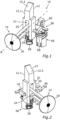
- Fig. 1
- eine perspektivische Vorderansicht eines erfindungsgemäßen Schlosses mit einem in einem Entkopplungszustand befindlichen Koppelelement;
- Fig. 2
- eine weitere perspektivische Vorderansicht des Schlosses von
Fig. 1 ; - Fig. 3
- eine perspektivische Rückansicht des Schlosses von
Fig. 1 ; - Fig. 4
- eine weitere perspektivische Rückansicht des Schlosses von
Fig. 1 ; - Fig. 5
- eine Draufsicht auf das Schloss von
Fig. 1 ; - Fig. 6
- eine Rückansicht des Schlosses von
Fig. 1 ; - Fig. 7
- eine Seitenansicht des Schlosses von
Fig. 1 ; - Fig. 8
- eine Schnittansicht des Schlosses von
Fig. 1 entlang einer Ebene, die durch eine Bewegungsrichtung eines Riegels und eine Betätigungsrichtung eines Betätigungselements definiert ist; - Fig. 9
- eine weitere Schnittansicht des Schlosses von
Fig. 1 entlang einer Ebene, welche durch die Bewegungsrichtung des Riegels und eine Längsachse eines Kopplungsbolzens definiert ist; - Fig. 10
- eine Explosionsansicht des Schlosses von
Fig. 1 ; - Fig. 11A
- eine perspektivische Ansicht eines Riegels des Schlosses von
Fig. 1 ; - Fig. 11B
- eine weitere perspektivische Ansicht des Riegels von
Fig. 11A ; - Fig. 12
- eine perspektivische Ansicht des Koppelelements von
Fig. 1 ; - Fig. 13A
- eine perspektivische Ansicht eines Steuerelements des Schlosses von
Fig. 1 ; - Fig. 13B
- eine Draufsicht auf das Steuerelement von
Fig. 13A ; - Fig. 14
- das Schloss von
Fig. 1 mit im Entkopplungszustand befindlichem Koppelelement, wobei das Koppelelement in die Aktivposition über-führt ist; - Fig. 15.
- das Schloss von
Fig. 1 mit im Kopplungszustand befindlichem Koppelelement, wobei das Koppelelement in die Aktivposition und der Riegel in die Entriegelungsposition überführt ist. - In
Fig. 1 bis 15 ist ein Schloss 10, insbesondere für ein Elektrofahrrad und beispielsweise zum Sichern eines Energiespeichers an dem Elektrofahrrad, dargestellt. Grundsätzlich kann das Schloss jedoch auch zur Verriegelung von Türen, Fenstern, Schubladen, Transportkisten, Containern oder allgemein als Ersatz für ein mechanisches Schloss eingesetzt werden. Das Schloss 10 umfasst einen Verriegelungsmechanismus mit einem Riegel 12, welcher einen Verriegelungsabschnitt 12.1 aufweist. Der Riegel 12 ist zwischen einer inFig. 1 dargestellten Verriegelungsposition und Entriegelungsposition bewegbar (Fig. 15 ). In der Verriegelungsposition kann der Verriegelungsabschnitt 12.1 des Riegels 12 mit einem relativ zu dem Verriegelungsmechanismus bewegbaren Gegenstück, beispielsweise den Energiespeicher (nicht gezeigt), in Eingriff gebracht werden, um dieses in dem Schloss 10 zu sichern, wobei die Entriegelungsposition die Freigabe des Gegenstücks vorgesehen ist. - Zur Bewegung des Riegels von der Verriegelungsposition in die Entriegelungsposition umfasst das Schloss 10 ein manuell betätigbares Betätigungselement 14, das in der gezeigten Ausführungsform eine Handhabe 16 in Form eines Druccknopfes umfasst. Bei einer Betätigung des Druckknopfes wird das Betätigungselement 14 entlang einer Betätigungsachse B in Richtung des Riegels verschoben.
- Das Betätigungselement 14 wirkt nicht unmittelbar auf den Riegel 12 ein, um diesen in die Entriegelungsposition zu bewegen. Stattdessen ist ein Koppelelement 18 vorgesehen, welches mit dem Betätigungselement 14 in Eingriff steht (
Fig. 8 ) und durch dieses von einer Passivposition, wie sie inFig. 1 gezeigt ist (vgl. auchFig. 8 ), in eine Aktivposition, wie sie inFig. 14, 15 gezeigt ist, bewegbar ist. - Das Koppelelement 18 ist parallel zu dem Riegel 12 bewegbar angeordnet. Der Riegel 12 und das Koppelelement 18 weisen eine gemeinsame Längsachse L auf (
Fig. 10 ), die zugleich die Bewegungsrichtung von Riegel 12 und Koppelelement 18 definiert. Das Koppelelement 18 ist in einem durch den Riegel 12 gebildeten Führungsabschnitt 20 geführt, welcher einen zentral innerhalb des Riegels 12 ausgebildeten Führungsschacht 21 umfasst, in dem das Koppelelement 18 gleitend gelagert ist. Der Führungsschacht 21 weist eine laterale Breite S auf, die in etwa einer lateralen Ausdehnung D des Koppelelements 18 entspricht (Fig. 11A, 12 ). - Die Längsachse L des Riegels 12 und des Koppelelements 18 und somit deren Bewegungsrichtung ist senkrecht zu der Bewegungsrichtung des Betätigungselements 14 entlang der Betätigungsachse B orientiert. Um die Betätigungsbewegung des Betätigungselements 14 in die dazu senkrechte Riegelbewegung umzuwandeln, weist das Betätigungselement 14 einen Übertragungsabschnitt 22 auf, der eine erste schräge Steuerfläche 24 aufweist. Dazu korrespondierend weist das Koppelelement 18 eine zweite schräge Steuerfläche 26 auf, entlang derer die erste schräge Steuerfläche 24 des Betätigungselements 14 gleitend in Richtung der Betätigungsachse B bewegbar ist (
Fig. 8 ). - Das Koppelelement 18 ist mittels einer Feder 28 bewegbar gelagert und wird beim Eindrücken des Betätigungselements 14 durch die erste schräge Steuerfläche 24 entgegen der Rückstellkraft der Feder 28 in Richtung seiner Längsachse L in seine Aktivposition gedrängt (
Fig. 14 ). Das Koppelelement 18 weist zur Lagerung auf der Feder 28 eine Lageraussparung 30 auf, in welche die als Spiralfeder ausgebildete Feder 28 eingreifen kann. Durch einen Lagerfortsatz 32 sitzt das Koppelelement 18 stabil auf der Feder 28 (Fig. 12 ). - Mittels derselben Feder 28 ist der Riegel 12 gelagert, sodass er entgegen der Rückstellkraft der Feder 28 aus seiner Verriegelungsposition in die Entriegelungsposition bringbar ist. Der Riegel 12 weist an seinem dem Verriegelungsabschnitt 12.1 abgewandten Ende eine im Wesentlichen ringförmige Lageraussparung 34 zum Eingreifen der Feder 28 auf, wobei ein stabiler Sitz des Riegels auf der Feder durch zwei Lagerzungen 36 sichergestellt ist, die die ringförmige Lageraussparung 34 innenseitig abschnittsweise begrenzen (
Fig. 11A, B ). - Durch die Lagerung des Riegels 12 mittels der Feder 28 kann eine Fallenfunktion des Schlosses 10 realisiert werden. Das Einsetzen eines Gegenstücks in den Verriegelungsmechanismus, beispielsweise des Energiespeichers, kann bei in dem Verriegelungszustand befindlichem Riegel 12 erfolgen, da der Riegel 12 beim Einsetzen des Gegenstücks gegen die Rückstellkraft der Feder 28 zwischenzeitlich in seine Entriegelungsposition gedrückt wird. Dazu ist eine Steuerschräge 12.2 an dem Riegel vorgesehen. Ist das Gegenstück vollständig in das Schloss 10 eingesetzt, wird der Riegel 12 durch die Feder 28 automatisch in seine Verriegelungsposition gedrängt, sodass sofort ein Verlierschutz für das Gegenstück besteht.
- Gemäß
Fig. 1 bis Fig. 9 undFig. 14 befindet sich das Koppelelement 18 in einem Entkopplungszustand, in welchem es relativ zu dem Riegel 12 bewegbar angeordnet ist, sodass eine Bewegung des Betätigungselements 14 und eine dadurch erzeugte Bewegung des Koppelelements 18 von der Passivposition in die Aktivposition ohne Effekt auf den Riegel 12 bleibt (Fig. 14 ). Um mittels des Betätigungselements 14 den Riegel 12 in seine Entriegelungsposition bewegen zu können, kann das Koppelelement 18 in einen Kopplungszustand überführt werden, in welchem es mit dem Riegel 12 gekoppelt ist. In dem Kopplungszustand wird bei einer Betätigung des Betätigungselements 14, das Koppelelement 18 in die Aktivposition überführt und der mit dem Koppelelement 18 gekoppelte Riegel 12 dabei in seine Entriegelungsposition mitgenommen (Fig. 15 ). - Um das Koppelelement 18 in den Kopplungszustand bzw. in den Entkopplungszustand zu überführen, ist ein Steuerelement 38 vorgesehen (
Fig. 13A, B ). In dem gezeigten Ausführungsbeispiel ist das Steuerelement 38 als Steuergabel 40 ausgebildet, welche neben einer Aufhängungsstrebe 42 einen ersten Zinken 44.1 und einen zweiten Zinken 44.2 umfasst. Die Steuergabel 40 umgreift den Riegel 12 an drei Seiten, wobei die durch die Steuergabel 40 umgriffene Fläche 46 in dem Verriegelungszustand des Riegels 12 bzw. in der Passivposition des Koppelelements 18 im Wesentlichen senkrecht zu der Längsachse L des Riegels orientiert ist. - Das Steuerelement 38 weist zudem einen Kopplungsbolzen 48 auf, der sich zwischen dem ersten und zweiten Zinken 44.1, 44.2 erstreckt und dessen Längsachse K senkrecht zu den Zinken 44.1, 44.2 und zu der Bewegungsrichtung und Längsachse L des Riegels 12 und des Koppelelements 18 orientiert ist (
Fig 10 ,13B ). Der Kopplungsbolzen 48 ist an einem der Aufhängungsstrebe 42 gegenüberliegenden Ende der Steuergabel 40 angeordnet und trifft bezüglich der Betätigungsachse B in dem montierten Schloss 10 mittig auf den Riegel 12 und das Koppelelement 18 (Fig. 2 ,7 ). - Um das Steuerelement 38 und insbesondere den Kopplungsbolzen 48 des Steuerelements 38 aufnehmen zu können, weisen das Koppelelement 18 und der Riegel 12 jeweils entsprechende Aussparungen auf. Das Koppelelement 18 weist eine Durchtrittsöffnung 52 auf, deren Durchmesser das Hindurchtreten des Kopplungsbolzens 48 in axialer Richtung erlaubt (
Fig 12 ). Der Riegel 12 weist eine erste Durchtrittsöffnung 54.1 und eine zweite Durchtrittsöffnung 54.2 auf, welche in Bezug auf die Längsachse K des Kopplungsbolzens 48 an gegenüberliegenden Seiten des Riegels 12 angeordnet sind. Durch die gemeinsame Lagerung des Riegels 12 und des Koppelelements 18 mittels der Feder 28 ist sichergestellt, dass in der Passivposition die Durchtrittsöffnungen 52, 54.1, 54.2 des Koppelelements 18 und des Riegels 12 fluchtend miteinander ausgerichtet sind. - Der Kopplungsbolzen 48 ist zweiteilig ausgebildet und umfasst einen ersten Kopplungsbolzenabschnitt 48.1 und einen zweiten Kopplungsbolzenabschnitt 48.2, welche durch eine Lücke 50 getrennt sind. Die Lücke 50 weist entlang der Längsachse K des Kopplungsbolzens 48 in etwa die lateralen Breite S des in dem Riegel 12 angeordneten Führungsschachts 21 auf. Das Koppelelement 18 kann daher in der Lücke 50 derart angeordnet werden, dass es nicht mit dem Kopplungsbolzen 48 in Eingriff gelangt. Dies charakterisiert gerade den Entkopplungszustand gemäß
Fig. 1 bis Fig. 9 undFig. 14 und ist in der Schnittdarstellung durch den Kopplungsbolzen 48 gemäßFig. 9 dargestellt. Das Koppelelement 18 kann daher in dem Entkopplungszustand durch das Betätigungselement 14 unabhängig von dem Steuerelement 38 relativ zu diesem bewegt werden (Fig. 14 ). - In dem Entkopplungszustand gemäß
Fig. 1 bis Fig. 9 undFig. 14 steht der Riegel 12 mit dem Steuerelement 38 mittels des ersten und des zweiten Kopplungsbolzenabschnitts 48.1, 48.2, welche in die erste bzw. zweite Durchtrittsöffnung 54.1, 54.2 eingeführt sind, in Eingriff (Fig. 2 ,9 ). Der erste Zinken 44.1 der Steuergabel 40 befindet sich nahezu in Anlage mit der Seite des Riegels 12, in welcher die erste Durchtrittsöffnung 54.1 angeordnet ist, und der erste Kopplungsbolzenabschnitt 48.1 ist vollständig in der Durchtrittsöffnung 54.1 angeordnet (Fig. 5 ). - Um das Koppelement 18 ausgehend von dem in
Fig. 1 bis Fig. 9 undFig. 14 gezeigten Entkopplungszustand in den Kopplungszustand - und gegebenenfalls umgekehrt - zu überführen, weist das Schloss 10 einen Elektromotor 56 auf, der mit dem Steuerelement 38 über die Aufhängungsstrebe 42 verbunden ist. Die Aufhängungsstrebe 42 weist eine Gelenkrinne 58 auf, welche im gezeigten Ausführungsbeispiel mit einem auf einer Welle 63 des Elektromotors 56 sitzenden Schwenkarm 60 gelenkig verbunden ist, wobei der Schwenkarm 60 in wohldefinierte Stellungen verschwenkt werden kann (Pfeil 65 inFig. 5 ). Eine inFig. 14 gezeigte erste Stellung des Schwenkarms 60 entspricht dem Entkopplungszustand gemäßFig. 1 bis Fig. 9 und eine inFig. 15 gezeigte zweite Stellung des Schwenkarms 60 dem Kopplungszustand des Koppelements 18. - Ein Verschwenken des Schwenkarms 60 von der ersten Stellung gemäß
Fig. 14 in die zweite Stellung gemäßFig. 15 führt zu einer Linearverschiebung des Steuerelements 38 entlang der Längsachse K des Kopplungsbolzens 48, wobei die Richtung 62 der Linearverschiebung inFig. 9 durch einen Pfeil 62 gekennzeichnet ist. Durch die Linearverschiebung wird der erste Kopplungsbolzenabschnitt 48.1 aus der ersten Durchtrittsöffnung 54.1 herausgeschoben und so außer Eingriff mit dem Riegel 12 gebracht. Der zweite Kopplungsbolzenabschnitt 54.2 wird vollständig durch die zweite Durchtrittsöffnung 54.2 hindurch und in die Durchtrittsöffnung 52 des Koppelelements 18 hineingeführt. Auf diese Weise werden der Riegel 12 und das Koppelement 18 durch den Kopplungsbolzen 48 und insbesondere durch den zweiten Kopplungsbolzenabschnitt 48.2 des Steuerelements 38 miteinander gekoppelt, d.h. also das Koppelelement 18 in seinen Kopplungszustand gebracht (Fig. 15 ). - In diesem Kopplungszustand ist das Koppelelement 18 in Bezug auf die Bewegungsrichtung entlang der Längsachse L des Koppelelements 18 starr mit dem Riegel 12 verbunden, sodass dieser bei Betätigung des Betätigungselements 14 durch das Koppelelement 18 in seine Entriegelungsposition mitgenommen wird. Dabei wird auch der Kopplungsbolzen 48 entlang der Längsachse L des Riegels 12 mitgenommen, sodass das Steuerelement 38 rotiert wird, wobei eine Längsachse der Gelenkrinne 58 in Richtung des Riegels 12 verkippt wird (
Fig. 15 ). Die Gelenkrinne 58 ist auf zwei Seiten von abgerundeten Wandabschnitten 64 begrenzt, zwischen denen ein Nockenabschnitt 66 des Schwenkarms 60 aufgenommen ist. Zusätzlich zu der Rotationsbewegung des Steuerelements 38 in Richtung des Riegels 12 kann auch eine Translationsbewegung des Steuerelements 38 in Richtung auf den Riegel 12 zu, insbesondere parallel zu der Betätigungsachse B, vorgesehen sein, durch welche sichergestellt ist, dass der Riegel 12 mit seinen Durchtrittsöffnungen 54.1, 54.2, das Koppelelement 18 mit seiner Durchtrittsöffnung 52 und der Kopplungsbolzen 48 bezüglich der Betätigungsachse B stets miteinander ausgerichtet sind. In der Gesamtbetrachtung wird der Kopplungsbolzen 48 des Steuerelements 38 somit effektiv parallel zu der Längsachse L des Riegels verschoben. Die Wandabschnitte 64 sind derart ausgebildet, dass sie eine sichere Führung des Steuerelements 38 während der Rotationsbewegung sowie der Translationsbewegung bieten. - Der Riegel 12 steht mit dem Steuerelement 38 nicht nur in dem Kopplungszustand, sondern auch in dem Entkopplungszustand in Eingriff (
Fig. 9 ), wobei der Riegel 12 und das Steuerelement 38 miteinander beweglich verbunden sind. Insbesondere ist eine relative Rotation um die Längsachse K des Kopplungsbolzens 48 (Fig. 15 ), sowie eine relative Translation in Richtung des Pfeils 62 bzw. in umgekehrter Richtung möglich (Fig. 9 ). - Das Schloss 10 weist zudem ein Sperrelement 68 auf, das in dem gezeigten Ausführungsbeispiel als Sperrzapfen an dem Steuerelement 38 ausgebildet ist, der sich koaxial mit dem Kopplungsbolzen 48 von dem zweiten Zinken 44.2 zu einer Außenseite der Steuergabel 40 hin erstreckt. Das Sperrelement 68 kann zwischen einer Sperrstellung, in welcher der Riegel 12 durch das Sperrelement 68 in seiner Verriegelungsposition gesperrt ist, und einer Freigabestellung, in welcher der Riegel 12 in seine Entriegelungsposition bewegbar ist, verstellt werden. Um eine Bewegung des Riegels 12 aus seiner Verriegelungsposition heraus zu blockieren, kann das Sperrelement 68 in seiner Sperrstellung mit einer Komponente des Schlosses 10 in Eingriff stehen. Im gezeigten Ausführungsbeispiel ist vorgesehen, dass das Sperrelement 68 in der Sperrstellung mit einem nicht beweglichen Gehäuse des Schlosses 10, konkret mit einer Gehäusewand 70 in Eingriff steht (
Fig. 9 ). In die Gehäusewand 70 ist zu diesem Zweck eine Öffnung 72 eingebracht, die das Sperrelement 68 in seinem Sperrzustand aufnimmt und eine Bewegung des Sperrelements 68 entlang der Längsachse L des Riegels 12 blockiert. - Da das Sperrelement 68 an dem Steuerelement 38 ausgebildet ist, welches mittels des Kopplungsbolzens 48 und konkret mittels des zu dem Sperrelement 68 koaxialen zweiten Kopplungsbolzenabschnitts 48.2 stets mit dem Riegel 12 verbunden ist, ist durch das Festsetzen des Sperrelements 68 in der Sperrstellung auch eine Bewegung des Riegels 12 entlang seiner Längsachse L und somit ein Bewegen in die Entriegelungsposition blockiert.
- Die Verstellung des Sperrelements 68 von der Sperrstellung gemäß
Fig. 9 in die Freigabestellung erfolgt mittels des Elektromotors 56. Indem dieser das Steuerelement 38 entlang der Richtung 62 linear verschiebt (Fig. 9 ), wird das Sperrelement 68 aus der Öffnung 72 der Gehäusewand 70 gelöst und somit eine Bewegung entlang der Längsachse L des Riegels 12 ermöglicht. - Die Bewegung des Sperrelements 68 in die Freigabestellung geht zugleich einher mit einer Überführung des Koppelelements 18 in seinen Kopplungszustand, sodass einerseits die Bewegung des Riegels 12 in die Entriegelungsposition nicht mehr durch das Sperrelement blockiert wird und andererseits eine Betätigung des Betätigungselements 14 tatsächlich ein Verstellen des Riegels 12 in die Entriegelungsposition ermöglicht.
- Andererseits befindet sich gemäß der gezeigten Ausführungsform bei in Sperrstellung befindlichem Sperrelement 68 das Koppelelement 18 zugleich in seinem Entkopplungszustand. Somit wird einerseits das Betätigen des Riegels 12 mittels des Betätigungselements 14 und somit auch die Manipulierbarkeit des Schlosses 10 ausgeschlossen, während durch das Sperrelement 68 ein unbeabsichtigtes Verstellen des Riegels 12 in die Entriegelungsposition zusätzlich verhindert wird.
- Es versteht sich, dass das Sperrelement 68 mit der Öffnung 72 der Gehäusewand ausgerichtet sein muss, damit das Sperrelement 68 mit der Öffnung 72 in Eingriff gebracht werden kann, d.h. also in diese einfahren kann. Mit anderen Worten setzt die Überführung des Sperrelements 68 aus der Freigabestellung zurück in die Sperrstellung voraus, dass sich der Riegel 12 in seiner Verriegelungsposition befindet. Kehrt der Riegel 12 hingegen ausgehend von seiner Entriegelungsposition nicht vollständig in seine Verriegelungsposition zurück, beispielsweise weil der zu sichernde Energiespeicher nicht korrekt eingesetzt wurde, so kann aufgrund der mangelnden Ausrichtung mit der Öffnung 72 der Gehäusewand 70 auch das mit dem Riegel 12 gekoppelte Sperrelement 68 nicht in die Öffnung 72 einfahren und folglich nicht seine Sperrstellung erreichen. Entsprechend erreicht das Koppelelement 18 in diesem Fall nicht seinen Entkopplungszustand, d.h. es wird nicht von dem Riegel 12 entkoppelt.
- Da die Verlagerung des Sperrelements 68 aus der Freigabestellung zurück in die Sperrstellung mittels des Elektromotors 56 erfolgt, kann mittels des Elektromotors 56 überwacht werden, ob das Sperrelement 68 seine Sperrstellung erreicht oder nicht. Beispielsweise kann es sich bei dem Elektromotor 56 um einen Schrittmotor handeln, mit dessen Hilfe detektierbar ist, wie weit sich das Sperrelement 68 tatsächlich bewegen lässt. Alternativ kann aus einer erhöhten Leistungsaufnahme des Elektromotors 68 geschlossen werden, dass das Sperrelement 68 an der Gehäusewand 70 anstößt anstatt in die Öffnung 72 einzufahren.
- Wird mittels des Elektromotors 56 festgestellt, dass das Sperrelement 68 seine Sperrstellung nicht erreichen kann und sich der Riegel 12 somit nicht in seiner Verriegelungsposition befindet, so kann an den Benutzer des Schlosses 10 eine entsprechende Warnung ausgegeben werden, damit der Benutzer den Funktionszustand des Schlosses 10 und/oder die Lage des Energiespeichers überprüfen und gegebenenfalls korrigieren kann. Konkret kann die Warnung, z.B. in Form einer optischen und/oder akustischen Rückmeldung, an einem Bordcomputer des Elektrofahrrads, an einem Mobiltelefon des Benutzers und/oder an dem Schloss 10 selbst ausgegeben werden.
-
- 10
- Schloss
- 12
- Riegel
- 12.1
- Verriegelungsabschnitt
- 12.2
- Steuerschräge
- 14
- Betätigungselement
- 16
- Handhabe
- 18
- Koppelelement
- 20
- Führungsabschnitt
- 21
- Führungsschacht
- 22
- Übertragungsabschnitt
- 24
- erste schräge Steuerfläche
- 26
- zweite schräge Steuerfläche
- 28
- Feder
- 30
- Lageraussparung des Koppelelements
- 32
- Lagerfortsatz des Koppelelements
- 34
- ringförmige Lageraussparung des Riegels
- 36
- Lagerzungen des Riegels
- 38
- Steuerelement
- 40
- Steuergabel
- 42
- Aufhängungsstrebe
- 44.1
- erster Zinken
- 44.2
- zweiter Zinken
- 46
- umgriffene Fläche
- 48
- Kopplungsbolzen
- 48.1
- erster Kopplungsbolzenabschnitt
- 48.2
- zweiter Kopplungsbolzenabschnitt
- 50
- Lücke des Kopplungsbolzens
- 52
- Durchtrittsöffnung des Koppelelements
- 54.1
- erste Durchtrittsöffnung des Riegels
- 54.2
- zweite Durchtrittsöffnung des Riegels
- 56
- Elektromotor
- 58
- Gelenkrinne
- 60
- Schwenkarm
- 62
- Richtung der Linearverschiebung des Steuerelements
- 63
- Welle des Elektromotors
- 64
- abgerundete Wandabschnitte der Gelenkrinne
- 65
- Verschwenkrichtung des Schwenkarms
- 66
- Nockenabschnitt
- 68
- Sperrelement
- 70
- Gehäusewand
- 72
- Öffnung der Gehäusewand
- L
- Längsachse des Riegels und des Koppelelements
- D
- laterale Ausdehnung des Koppelelements
- S
- laterale Breite des Führungsschachts
- B
- Betätigungsachse des Betätigungselements
- K
- Längsachse des Kopplungsbolzens
Claims (15)
- Schloss (10) miteinem Verriegelungsmechanismus, welcher einen Riegel (12) aufweist, der zwischen einer zur Sicherung eines relativ zu dem Verriegelungsmechanismus bewegbaren Gegenstücks vorgesehenen Verriegelungsposition und einer zur Freigabe des Gegenstücks vorgesehenen Entriegelungsposition bewegbar ist, und miteinem Betätigungselement (14) zur manuellen Bewegung des Riegels (12) in die Entriegelungsposition,gekennzeichnet durchein Koppelelement (18), welches zwischen einem Kopplungszustand, in welchem es mit dem Riegel (12) gekoppelt ist, und einem Entkopplungszustand, in welchem es relativ zu dem Riegel (12) bewegbar ist, überführbar und mittels des Betätigungselements (14) von einer Passivposition in eine Aktivposition bewegbar ist,wobei der Riegel (12) durch eine Bewegung des im Kopplungszustand befindlichen Koppelelements (18) von der Passivposition in die Aktivposition durch das Betätigungselement (14) in die Entriegelungsposition bewegbar ist.
- Schloss (10) nach Anspruch 1,dadurch gekennzeichnet, dass das Koppelelement (18) parallel zu dem Riegel (12) bewegbar angeordnet ist; und/oderdadurch gekennzeichnet, dass die Bewegungsrichtung des Betätigungselements (14) zumindest im Wesentlichen senkrecht zu einer Bewegungsrichtung des Riegels (12) und/oder des Koppelelements (18) orientiert ist.
- Schloss (10) nach Anspruch 1 oder 2,
dadurch gekennzeichnet, dass der Riegel (12) einen Führungsabschnitt (20) aufweist, in welchem das Koppelelement (18) geführt ist. - Schloss (10) nach zumindest einem der vorstehenden Ansprüche, gekennzeichnet durch ein Steuerelement (38) zum wahlweisen Überführen des Koppelelements (18) in den Kopplungszustand oder Entkopplungszustand,
insbesondere wobei der Riegel (12) und das Koppelelement (18) in dem Kopplungszustand durch das Steuerelement (38) gekoppelt sind, insbesondere wobei das Steuerelement (38) als Steuergabel (40) ausgebildet ist, welche den Riegel (12) an drei Seiten umgreift, und/oder dass das Steuerelement (38) zumindest einen Kopplungsbolzen (48), insbesondere dessen Längsachse sich senkrecht zu einer Bewegungsrichtung des Riegels (12) erstreckt, zur Kopplung des Riegels (12) und des Koppelelements (18) aufweist. - Schloss (10) nach Anspruch 4,wobei das Koppelelement (18) und der Riegel (12) jeweils zumindest eine Aussparung zur Aufnahme des Steuerelements (38), insbesondere eines Kopplungsbolzens (48) des Steuerelements (38), aufweisen; und/oder wobei das Steuerelement (38) und der Riegel (12) beweglich miteinander verbunden sind; und/oderwobei eine Bewegung des Riegels (12) aus der Verriegelungsposition in die Entriegelungsposition eine Rotationsbewegung des Steuerelements (38) bewirkt.
- Schloss (10) nach zumindest einem der vorstehenden Ansprüche, gekennzeichnet durch ein Sperrelement (68), das zwischen einer Sperrstellung, in welcher der Riegel (12) in seiner Verriegelungsposition gesperrt ist, und einer Freigabestellung verstellbar ist, in welcher der Riegel (12) in seine Entriegelungsposition bewegbar ist, insbesondere wobei das Sperrelement als Stift oder Zapfen ausgebildet ist.
- Schloss (10) nach Anspruch 4 oder 5 und 6,
dadurch gekennzeichnet, dass das Sperrelement (68) an dem Steuerelement (38) ausgebildet ist. - Schloss (10) nach Anspruch 6 oder 7,
dadurch gekennzeichnet, dass das Sperrelement (68) in seiner Sperrstellung mit einer Komponente des Schlosses (10) in Eingriff steht, insbesondere mit einer nicht beweglichen Komponente, wie beispielsweise einem Gehäuse (70), des Schlosses (10). - Schloss (10) nach zumindest einem der vorstehenden Ansprüche,dadurch gekennzeichnet, dass der Riegel (12) entgegen einer Rückstellkraft einer Feder (28) aus der Verriegelungsposition in die Entriegelungsposition bringbar ist, und/oder dass das Koppelelement (18) entgegen der Rückstellkraft einer Feder (28) aus der Passivposition in die Aktivposition bringbar ist,insbesondere wobei der Riegel (12) und das Koppelelement (18) entgegen der Rückstellkraft derselben Feder (28) in die Entriegelungsposition bzw. in die Aktivposition bringbar sind.
- Schloss (10) nach zumindest einem der vorstehenden Ansprüche,
dadurch gekennzeichnet, dass das Schloss (10) zumindest einen Aktor (56) zur Überführung des Koppelelements (18) zwischen dem Kopplungszustand und dem Entkopplungszustand und/oder zur Verstellung eines Sperrelements (68) zwischen seiner Sperrstellung und seiner Freigabestellung umfasst. - Schloss (10) nach zumindest Anspruch 4,
dadurch gekennzeichnet, dass das Schloss (10) zumindest einen Aktor (56) zur Betätigung des Steuerelements (38) umfasst. - Schloss (10) nach zumindest einem der vorstehenden Ansprüche,
gekennzeichnet durch ein Detektionsmittel zur Detektion der Einnahme der Verriegelungsposition durch den Riegel (12). - Schloss (10) nach zumindest Anspruch 12,
dadurch gekennzeichnet, dass das Detektionsmittel einen Aktor (56) zur Verstellung eines Sperrelements (68) umfasst, das zwischen einer Sperrstellung, in welcher der Riegel (12) in seiner Verriegelungsposition gesperrt ist, und einer Freigabestellung verstellbar ist, in welcher der Riegel (12) in seine Entriegelungsposition bewegbar ist. - Schloss (10) mit einem Verriegelungsmechanismus, welcher einen Riegel (12) aufweist, der zwischen einer zur Sicherung eines relativ zu dem Verriegelungsmechanismus bewegbaren Gegenstücks vorgesehenen Verriegelungsposition und einer zur Freigabe des Gegenstücks vorgesehenen Entriegelungsposition bewegbar ist, gekennzeichnet durch ein Detektionsmittel zur Detektion der Einnahme der Verriegelungsposition durch den Riegel (12).
- Schloss (10) nach Anspruch 14,dadurch gekennzeichnet, dass das Detektionsmittel einen Aktor (56) zur Verstellung eines Sperrelements (68) umfasst, das zwischen einer Sperrstellung, in welcher der Riegel (12) in seiner Verriegelungsposition gesperrt ist, und einer Freigabestellung verstellbar ist, in welcher der Riegel (12) in seine Entriegelungsposition bewegbar ist; und/oder gekennzeichnet durch ein Betätigungselement (14) zur manuellen Bewegung des Riegels (12) in die Entriegelungsposition und ein Koppelelement (18), welches zwischen einem Kopplungszustand, in welchem es mit dem Riegel (12) gekoppelt ist, und einem Entkopplungszustand, in welchem es relativ zu dem Riegel (12) bewegbar ist, überführbar und mittels des Betätigungselements (14) von einer Passivposition in eine Aktivposition bewegbar ist, wobei der Riegel (12) durch eine Bewegung des im Kopplungszustand befindlichen Koppelelements (18) von der Passivposition in die Aktivposition durch das Betätigungselement (14) in die Entriegelungsposition bewegbar ist; und/odergekennzeichnet durch wenigstens eines der Merkmale der Ansprüche 2 bis 11.
Priority Applications (3)
| Application Number | Priority Date | Filing Date | Title |
|---|---|---|---|
| TW111132525A TW202314101A (zh) | 2021-09-02 | 2022-08-29 | 鎖 |
| US17/898,500 US12516550B2 (en) | 2021-09-02 | 2022-08-30 | Lock |
| CN202211072449.XA CN115749450A (zh) | 2021-09-02 | 2022-09-02 | 锁 |
Applications Claiming Priority (1)
| Application Number | Priority Date | Filing Date | Title |
|---|---|---|---|
| DE102021122786.0A DE102021122786A1 (de) | 2021-09-02 | 2021-09-02 | Schloss |
Publications (3)
| Publication Number | Publication Date |
|---|---|
| EP4144940A2 true EP4144940A2 (de) | 2023-03-08 |
| EP4144940A3 EP4144940A3 (de) | 2023-06-21 |
| EP4144940B1 EP4144940B1 (de) | 2026-04-29 |
Family
ID=82608417
Family Applications (1)
| Application Number | Title | Priority Date | Filing Date |
|---|---|---|---|
| EP22185026.6A Active EP4144940B1 (de) | 2021-09-02 | 2022-07-14 | Schloss |
Country Status (5)
| Country | Link |
|---|---|
| US (1) | US12516550B2 (de) |
| EP (1) | EP4144940B1 (de) |
| CN (1) | CN115749450A (de) |
| DE (1) | DE102021122786A1 (de) |
| TW (1) | TW202314101A (de) |
Cited By (1)
| Publication number | Priority date | Publication date | Assignee | Title |
|---|---|---|---|---|
| EP4585778A1 (de) * | 2024-01-12 | 2025-07-16 | ABUS August Bremicker Söhne KG | Schloss |
Families Citing this family (1)
| Publication number | Priority date | Publication date | Assignee | Title |
|---|---|---|---|---|
| DE102021105648A1 (de) * | 2021-03-09 | 2022-09-15 | ABUS August Bremicker Söhne Kommanditgesellschaft | Verfahren zum Betreiben eines Fahrzeugschlosses |
Family Cites Families (33)
| Publication number | Priority date | Publication date | Assignee | Title |
|---|---|---|---|---|
| US1169659A (en) * | 1915-10-13 | 1916-01-25 | Clark N Lowell | Lock. |
| US1965939A (en) * | 1931-11-09 | 1934-07-10 | Briggs & Stratton Corp | Compartment lock |
| US1968285A (en) * | 1932-08-20 | 1934-07-31 | John J Egan | Doorlatch |
| US2186666A (en) * | 1938-10-07 | 1940-01-09 | Cereda Jose Aurelio | Mechanism for operating locks, latches, and the like |
| DE803698C (de) * | 1948-10-02 | 1951-04-09 | Ernst Diessl | Griff fuer Verschluesse von Tueren, Fenstern, Klappen u. dgl. |
| US2786706A (en) * | 1952-03-08 | 1957-03-26 | Raymond O Wright | Pressure responsive door latch actuator |
| US2765648A (en) * | 1953-03-13 | 1956-10-09 | Curtis M Hatcher | Electro-magnetic vehicle door lock |
| DE7337299U (de) * | 1972-10-20 | 1976-05-20 | Neiman & Co Kg, 5600 Wuppertal | Druckknopfbetaetigtes riegelschloss |
| AT349929B (de) * | 1976-10-18 | 1979-05-10 | Schuermann Hugo | Fallenriegelschloss |
| US4226451A (en) * | 1978-10-27 | 1980-10-07 | Hilaire Gingras | Safety latch |
| NO143356C (no) * | 1979-07-05 | 1981-04-01 | Elkem Spigerverket As | Anordning ved laas. |
| FR2594877B1 (fr) * | 1986-02-24 | 1991-06-21 | Fichet Bauche | Dispositif de verrouillage et deverrouillage d'un organe quelconque, tel que par exemple une barre comportant des penes |
| US5588318A (en) * | 1992-07-23 | 1996-12-31 | Fireking International, Inc. | Door lock |
| US5943888A (en) * | 1997-12-15 | 1999-08-31 | Lawson; Edward | Keyless entry mechanism |
| WO1999046464A2 (en) | 1998-03-09 | 1999-09-16 | Southco, Inc. | Latch |
| US6318138B1 (en) * | 1999-11-15 | 2001-11-20 | Kurt Mathews | Remotely controlled door lock |
| GB2428733B (en) * | 2005-07-30 | 2010-03-10 | Arvinmeritor Light Vehicle Sys | Vehicle door latch |
| DE102008014488B4 (de) * | 2008-03-17 | 2013-11-07 | Dorma Gmbh + Co. Kg | Türschloss mit ein- und auskoppelbarer Handhabe |
| EP2141664B1 (de) * | 2008-07-02 | 2012-03-14 | Ojmar S.A. | Programmierbare elektronische Sperre |
| US8757675B2 (en) * | 2009-03-31 | 2014-06-24 | The Young Engineers, Inc. | Two assembly parts latch system |
| US8789858B2 (en) * | 2009-03-31 | 2014-07-29 | The Young Engineers, Inc. | Two assembly parts latch system |
| DE102011050495A1 (de) | 2011-05-19 | 2012-11-22 | Dorma Gmbh + Co. Kg | Elektronische Einheit für eine Sperrvorrichtung und Schließsystem |
| DE102012106722B4 (de) | 2012-07-24 | 2017-11-30 | K.A. Schmersal Holding Gmbh & Co. Kg | Zuhaltung für eine Zugangsschutzvorrichtung mit einer Hilfsentriegelung |
| US9784017B2 (en) * | 2014-12-01 | 2017-10-10 | I-Tek Metal Mfg. Co., Ltd | Lock device with a electric locking function |
| DE102015113082A1 (de) * | 2015-08-07 | 2017-02-09 | Trelock Gmbh | Elektronisches Schloss |
| US12276140B2 (en) * | 2017-01-30 | 2025-04-15 | Kiekert Ag | Lock with assisted closing device for a motor vehicle |
| US11808056B2 (en) * | 2017-04-18 | 2023-11-07 | ASSA ABLOY Residential Group, Inc. | Door lock detection systems and methods |
| DE102019113163A1 (de) * | 2019-05-17 | 2020-11-19 | ABUS August Bremicker Söhne Kommanditgesellschaft | Mobiles Schloss |
| NL2023156B1 (en) * | 2019-05-17 | 2020-12-01 | Axa Stenman Nederland B V | Locking device for locking a battery unit, as well as a bicycle and a method for unlocking a battery unit |
| DE202019005536U1 (de) * | 2019-08-29 | 2021-02-10 | Marquardt Gmbh | Fahrzeug |
| DE102021105647A1 (de) * | 2020-03-17 | 2021-09-23 | ABUS August Bremicker Söhne Kommanditgesellschaft | Schloss |
| DE102020113825B4 (de) | 2020-05-22 | 2023-03-02 | Hermat-Metallwaren B. Porst GmbH | Betätigungseinrichtung für ein Schloss sowie Schlosssystem mit einer derartigen Betätigungseinrichtung |
| CN113027237A (zh) * | 2021-02-10 | 2021-06-25 | 北京骑胜科技有限公司 | 用于执行开锁操作的方法、锁具、车辆、服务器和系统 |
-
2021
- 2021-09-02 DE DE102021122786.0A patent/DE102021122786A1/de active Pending
-
2022
- 2022-07-14 EP EP22185026.6A patent/EP4144940B1/de active Active
- 2022-08-29 TW TW111132525A patent/TW202314101A/zh unknown
- 2022-08-30 US US17/898,500 patent/US12516550B2/en active Active
- 2022-09-02 CN CN202211072449.XA patent/CN115749450A/zh active Pending
Cited By (1)
| Publication number | Priority date | Publication date | Assignee | Title |
|---|---|---|---|---|
| EP4585778A1 (de) * | 2024-01-12 | 2025-07-16 | ABUS August Bremicker Söhne KG | Schloss |
Also Published As
| Publication number | Publication date |
|---|---|
| DE102021122786A1 (de) | 2023-03-02 |
| EP4144940B1 (de) | 2026-04-29 |
| US20230061981A1 (en) | 2023-03-02 |
| US12516550B2 (en) | 2026-01-06 |
| TW202314101A (zh) | 2023-04-01 |
| CN115749450A (zh) | 2023-03-07 |
| EP4144940A3 (de) | 2023-06-21 |
Similar Documents
| Publication | Publication Date | Title |
|---|---|---|
| EP1288026B1 (de) | Anhängekupplung | |
| DE102017101418B4 (de) | Türgriffanordnung für eine Fahrzeugtür | |
| EP1557298A1 (de) | Anhängekupplung | |
| EP2543804B1 (de) | Nebenschloss für ein Schloss | |
| EP1218612B1 (de) | Vorrichtung zur betätigung eines elektronischen schliesssystems und/oder eines in einer tür, einer klappe od. dgl. eingebauten schlosses, insbesondere bei einem fahrzeug | |
| WO2013156578A1 (de) | Selbstverriegelnde kompakt-kupplung | |
| DE102007045177A1 (de) | Verriegelungsvorrichtung | |
| EP4144940B1 (de) | Schloss | |
| DE102020113121A1 (de) | Verriegelungseinrichtung zum Verriegeln einer Batterieeinheit sowie ein Fahrrad und ein Verfahren zum Entriegeln einer Batterieeinheit | |
| DE19819603C2 (de) | Zentralgesteuerte Verschlußeinrichtung für einen Kraftfahrzeugtürverschluß | |
| EP2842847B1 (de) | Rahmenschloss | |
| DE4436617C1 (de) | Entriegelungsvorrichtung für einen Kraftfahrzeugtürverschluß | |
| EP2754798B1 (de) | Türschlossvorrichtung für eine Tür mit mindestens einem Türflügel | |
| DE4005641C2 (de) | ||
| EP2842846B1 (de) | Rahmenschloss | |
| EP4585778A1 (de) | Schloss | |
| EP1585880B1 (de) | Schliesshilfe zum schliessen einer tür bzw. klappe | |
| EP3633123A1 (de) | Flächenbündiger betätigungsgriff für eine schliessvorrichtung | |
| EP2626284B1 (de) | Rahmenschloss | |
| DE10339542B4 (de) | Kraftfahrzeugtürverschluss | |
| EP1191171A2 (de) | Kupplungsvorrichtung für Türverriegelungsanlagen | |
| DE3812331C2 (de) | Zentralverriegelungseinrichtung | |
| DE9210719U1 (de) | Türschloß | |
| DE102020213056A1 (de) | Entriegelungssystem | |
| EP1473429B1 (de) | Schloss |
Legal Events
| Date | Code | Title | Description |
|---|---|---|---|
| PUAI | Public reference made under article 153(3) epc to a published international application that has entered the european phase |
Free format text: ORIGINAL CODE: 0009012 |
|
| STAA | Information on the status of an ep patent application or granted ep patent |
Free format text: STATUS: THE APPLICATION HAS BEEN PUBLISHED |
|
| AK | Designated contracting states |
Kind code of ref document: A2 Designated state(s): AL AT BE BG CH CY CZ DE DK EE ES FI FR GB GR HR HU IE IS IT LI LT LU LV MC MK MT NL NO PL PT RO RS SE SI SK SM TR |
|
| PUAL | Search report despatched |
Free format text: ORIGINAL CODE: 0009013 |
|
| AK | Designated contracting states |
Kind code of ref document: A3 Designated state(s): AL AT BE BG CH CY CZ DE DK EE ES FI FR GB GR HR HU IE IS IT LI LT LU LV MC MK MT NL NO PL PT RO RS SE SI SK SM TR |
|
| RIC1 | Information provided on ipc code assigned before grant |
Ipc: B62M 6/90 20100101ALI20230517BHEP Ipc: B62J 43/13 20200101ALI20230517BHEP Ipc: B62H 5/00 20060101ALI20230517BHEP Ipc: E05B 71/00 20060101ALI20230517BHEP Ipc: E05B 55/06 20060101ALI20230517BHEP Ipc: E05B 47/00 20060101ALI20230517BHEP Ipc: E05B 1/00 20060101AFI20230517BHEP |
|
| STAA | Information on the status of an ep patent application or granted ep patent |
Free format text: STATUS: REQUEST FOR EXAMINATION WAS MADE |
|
| 17P | Request for examination filed |
Effective date: 20231221 |
|
| RBV | Designated contracting states (corrected) |
Designated state(s): AL AT BE BG CH CY CZ DE DK EE ES FI FR GB GR HR HU IE IS IT LI LT LU LV MC MK MT NL NO PL PT RO RS SE SI SK SM TR |
|
| REG | Reference to a national code |
Ref legal event code: R079 Ipc: E05B0047060000 Ref country code: DE Ref legal event code: R079 Ref document number: 502022007774 Country of ref document: DE Free format text: PREVIOUS MAIN CLASS: E05B0001000000 Ipc: E05B0047060000 |
|
| RIC1 | Information provided on ipc code assigned before grant |
Ipc: E05B 47/06 20060101AFI20251030BHEP Ipc: E05B 55/12 20060101ALI20251030BHEP Ipc: E05C 1/12 20060101ALI20251030BHEP Ipc: B62H 5/00 20060101ALI20251030BHEP Ipc: E05B 1/00 20060101ALI20251030BHEP Ipc: E05B 47/00 20060101ALI20251030BHEP Ipc: E05B 55/06 20060101ALI20251030BHEP Ipc: E05B 71/00 20060101ALI20251030BHEP |
|
| GRAP | Despatch of communication of intention to grant a patent |
Free format text: ORIGINAL CODE: EPIDOSNIGR1 |
|
| STAA | Information on the status of an ep patent application or granted ep patent |
Free format text: STATUS: GRANT OF PATENT IS INTENDED |
|
| INTG | Intention to grant announced |
Effective date: 20251204 |
|
| GRAS | Grant fee paid |
Free format text: ORIGINAL CODE: EPIDOSNIGR3 |
|
| GRAA | (expected) grant |
Free format text: ORIGINAL CODE: 0009210 |
|
| STAA | Information on the status of an ep patent application or granted ep patent |
Free format text: STATUS: THE PATENT HAS BEEN GRANTED |
|
| AK | Designated contracting states |
Kind code of ref document: B1 Designated state(s): AL AT BE BG CH CY CZ DE DK EE ES FI FR GB GR HR HU IE IS IT LI LT LU LV MC MK MT NL NO PL PT RO RS SE SI SK SM TR |
|
| REG | Reference to a national code |
Ref country code: CH Ref legal event code: F10 Free format text: ST27 STATUS EVENT CODE: U-0-0-F10-F00 (AS PROVIDED BY THE NATIONAL OFFICE) Effective date: 20260429 |
|
| REG | Reference to a national code |
Ref country code: CH Ref legal event code: R17 Free format text: ST27 STATUS EVENT CODE: U-0-0-R10-R17 (AS PROVIDED BY THE NATIONAL OFFICE) Effective date: 20260430 |