EP4144941B1 - Gâche réglable - Google Patents
Gâche réglable Download PDFInfo
- Publication number
- EP4144941B1 EP4144941B1 EP22193210.6A EP22193210A EP4144941B1 EP 4144941 B1 EP4144941 B1 EP 4144941B1 EP 22193210 A EP22193210 A EP 22193210A EP 4144941 B1 EP4144941 B1 EP 4144941B1
- Authority
- EP
- European Patent Office
- Prior art keywords
- flank
- retaining
- teeth
- stop member
- bolt
- Prior art date
- Legal status (The legal status is an assumption and is not a legal conclusion. Google has not performed a legal analysis and makes no representation as to the accuracy of the status listed.)
- Active
Links
Images



Classifications
-
- E—FIXED CONSTRUCTIONS
- E05—LOCKS; KEYS; WINDOW OR DOOR FITTINGS; SAFES
- E05B—LOCKS; ACCESSORIES THEREFOR; HANDCUFFS
- E05B15/00—Other details of locks; Parts for engagement by bolts of fastening devices
- E05B15/02—Striking-plates; Keepers; Bolt staples; Escutcheons
- E05B15/0205—Striking-plates, keepers, staples
- E05B15/024—Striking-plates, keepers, staples adjustable
- E05B15/0245—Movable elements held by friction, cooperating teeth, or the like
-
- E—FIXED CONSTRUCTIONS
- E05—LOCKS; KEYS; WINDOW OR DOOR FITTINGS; SAFES
- E05B—LOCKS; ACCESSORIES THEREFOR; HANDCUFFS
- E05B15/00—Other details of locks; Parts for engagement by bolts of fastening devices
- E05B15/02—Striking-plates; Keepers; Bolt staples; Escutcheons
- E05B15/0205—Striking-plates, keepers, staples
- E05B15/022—Striking-plates, keepers, staples movable, resilient or yieldable
-
- E—FIXED CONSTRUCTIONS
- E05—LOCKS; KEYS; WINDOW OR DOOR FITTINGS; SAFES
- E05B—LOCKS; ACCESSORIES THEREFOR; HANDCUFFS
- E05B17/00—Accessories in connection with locks
- E05B17/0025—Devices for forcing the wing firmly against its seat or to initiate the opening of the wing
Definitions
- the present invention relates to an adjustable striker for a frame capable of receiving a leaf equipped with a mechanism provided with a retractable bolt.
- One area of application envisaged is in particular, but not exclusively, that of anti-panic locks making it possible to easily open in a hurry, a leaf, i.e. a door, from the inside of a building towards the outside, when it is locked from the outside to the inside. Also, such doors, called “emergency doors”, close an opening delimited by a frame.
- Known adjustable strikers comprise a housing having a face intended to be applied against the amount of a frame and to be screwed there.
- the strikers further comprise a substantially prismatic stop member mounted adjustable inside the housing using two suitable screws.
- the stopping member has a front edge and two sides opposite each other with respect to this front edge. Thus, one of the sides of the stopping member is oriented towards the inside, while the other is oriented towards the outside.
- the frame receives the leaf mounted hinged vertically on the other upright of the frame and opposite the adjustable striker. And the leaf is equipped with a locking mechanism provided with a retractable bolt adapted to cooperate with the striker.
- the leaf is for example recalled by a door closer and when the latter causes it to pivot to close the opening, the retractable bolt abuts against one of the sides of the stopping member and it then retracts to allow the leaf to continue its course and come to engage completely inside the frame, while the bolt returns behind the stopping member to come to rest against its opposite side. The leaf is then held in a fixed position inside the frame.
- the striker and more precisely the stopping member, is adjustable inside the housing so as to be able to precisely adjust the relative position of the retractable bolt and the stopping member for optimal locking.
- This adjustment is made when mounting the leaf in the frame and the striker. And it can also be achieved when the frame and the leaf evolve over time and their relative position deviates from the original position. This development may be due to the aging of the building for example, to expansion or frequency of stresses. And it can then cause a locking fault.
- the document EP 0362040 B1 discloses an adjustable shutter lock striker, comprising a housing and a stopping member in the form of a bar comprising teeth which is adjustable mounted inside said housing.
- the position of the closed shutter, relative to a dormant part comprising the striker, is adjusted by exerting sufficient thrust on this shutter, which causes the movement of the stop member in translation following a step-by-step movement.
- a problem which arises and which the present invention aims to resolve is to provide an adjustable striker requiring less monitoring and consequently, which is less costly to operate, in order to be able to obtain the best possible closure of the leaf in the frame.
- an adjustable striker comprising a housing adapted to be mounted on a frame, said frame being capable of receiving a leaf equipped with a mechanism provided with a retractable bolt; and, a stop member mounted adjustable inside said housing, said stop member having a front edge and two sides opposite each other with respect to said front edge, one of said sides being adapted to receive said retractable bolt in abutment to cause the retraction of said bolt and authorize the engagement of said leaf inside said frame, while said bolt comes back to rest against the other side of said two sides to be able to maintain said leaf in a fixed position inside said frame.
- Said housing has inside a bearing face provided with retaining teeth, while said stopping member has hooking teeth extending in said one of said flanks, and said stopping member is adapted to be retracted inside said housing when said bolt abuts against said one of said flanks and then extends from said housing to come into contact with said bolt, while said hooking teeth engage in said retaining teeth to prevent the retraction of said stopping member when said bolt bears against said other side.
- a characteristic of the invention lies in the implementation of a self-adjusting stopping member.
- the stop member adjusts to an optimal position for retaining the retractable bolt. And this, regardless of the relative dimensional changes of the frame and the leaf over time and stress.
- said stopping member retracts inside said housing when said bolt comes to approach it by one of said sides, while the retractable bolt itself retracts inside its mechanism .
- the retractable bolt releases.
- the stopping member also releases and then cooperates with the retractable bolt so that the other side comes into contact with the retractable bolt.
- the retractable bolt then comes, via the leaf, to exert a reverse force on the other side of the stopping member. This causes the hooking teeth and the retaining teeth to engage and therefore block the stop member in the direction of retraction.
- the stopping member extends into the free space which extends between the housing and the retractable bolt until it comes into contact with the latter. And it is thanks to this characteristic that the striker which is the subject of the invention is self-adjusting.
- the adjustable striker comprises a return spring mounted inside said housing to cause the extension of said stop member.
- the stopping member has been retracted inside the housing by the movement of the retractable bolt, it extends outside the housing in the opposite way, thanks to the return spring, since it escapes the reach of the retractable bolt.
- the return spring is stiff predetermined which should be defined according to the effort required to retract the retractable bolt.
- said housing comprises a mounting face and a free edge running along said mounting face and said bearing face, and said retaining teeth have a retaining generator substantially parallel to said free edge.
- the stopping member is movable in translation in a direction perpendicular to the free edge and to the retaining teeth.
- said retaining teeth each have a retaining flank oriented towards the outside of said housing, said retaining flank being inclined along a mean plane close to a plane perpendicular to said bearing face.
- said retaining teeth each have a first sliding flank opposite said retaining flank, said first sliding flank being inclined at a substantially right angle relative to said retaining flank.
- the retaining teeth are asymmetrical. Furthermore, such a geometry of the first sliding sides makes it easier to extend the stopping member towards the outside of the housing.
- said hooking teeth have a hooking generator substantially parallel to said front edge.
- the hooking teeth extend in a direction parallel to the front edge and perpendicular to the direction of translation of the stopping member. In this way, the hooking teeth cooperate perfectly with the retaining teeth. Because in fact, the hooking teeth extend in a transverse direction common to the retaining teeth.
- said hooking teeth each have a hooking side oriented opposite to said front edge, said hooking side being inclined along a mean plane close to a plane perpendicular to said one of said side of said stopping member .
- the hooking side of the hooking teeth comes to apply flat against the retaining side of the retaining teeth, and in addition the joint plane between the hooking sides and the retaining sides are close to perpendicular to the direction translation of the stop member in the housing. In this way, better blocking of the stopping member with respect to the housing is obtained when the retaining teeth and the hooking teeth engage with each other.
- said hooking teeth each have a second sliding side opposite said hooking side, said second sliding side being inclined substantially at a right angle relative to said hooking side.
- the first sliding side of the retaining teeth cooperates with the second sliding side of the hooking teeth when the stopping member is driven towards the outside of the housing. In this way, driving the stopping member is facilitated. Also, during this movement, the stopping member tends to move away from the support face. Furthermore, the stopping member has play in a direction perpendicular to the bearing face of the housing as will be explained below.
- said other side of said stopping member is of cylindrical shape defined by a generatrix parallel to said front edge.
- said housing comprises members for guiding the translation of said stopping member.
- FIG. 1 shows an adjustable striker 10 comprising a housing 12 inside which a stopping member 14 is installed.
- the housing 12 has a support wall 16 opposite a longitudinal covering wall 18 which is substantially parallel.
- the longitudinal covering wall 18 is connected to the support wall 16, via two opposite inclined trapezoidal walls 20, 22 and a rear wall 24, which also joins the two opposite trapezoidal walls 20, 22.
- the housing 12 has an opening 26 located opposite the rear wall 24.
- the opening 26 is delimited in particular by a free edge 25 of the support wall 16.
- the housing 12 has, inside, a support face 28 on which the stopping member 14 rests. And the support wall 16 also defines a support face 29, opposite the face support wall 28. The support wall 16 defines a mean plane and the support face 28 defines another mean plane substantially parallel to the mean plane of the support wall 16.
- the stopping member 14 has a front edge 30 and on one side of the front edge 30, a flat side 32, and on the other opposite side, a cylindrical side 34.
- the flat side 32 extends along the same average plane, up to a heel 35 of the stopping member 14.
- the stop member 14 also has two opposite side faces 36, 38.
- the two opposite side faces 36, 38 join a guide face 45, substantially parallel to the flat side 32 and which extends in the extension of the cylindrical side 34 .
- the stop member 14 is held between two free wings 40, 42 located respectively equidistant from the two trapezoidal walls 20, 22.
- the two free wings 40, 42 extend inside the housing 12 from the wall longitudinal covering 18 and the rear wall 24.
- the two free wings 40, 42 have two guide edges 44, 46 which extend substantially equidistant between the longitudinal covering wall 18 and the support face 28 in a direction substantially parallel to the support face 28.
- the stop member 14 comprises two lateral ribs 48, 50 extending projecting from the two opposite lateral faces 36, 38.
- the two lateral ribs 48, 50 extend substantially parallel to the aforementioned mean plane defined by the flat side 32. Also, the two lateral ribs 48, 50 are adapted to respectively come into sliding support against the guide edges 44, 46.
- the stopping member 14 is movable in translation inside the housing 12 in a direction perpendicular to the support face 28 at a small amplitude which will be specified later.
- the lateral ribs 48, 50 come to rest against the guide edge 44, 46, the flat side 32 is substantially spaced from the support face 28 of the housing 12.
- the guide face 45 is in sliding support against the longitudinal covering wall 18 of the housing 12.
- the housing 12 has two fixing screws 52, 54 located on each side of the stop member 14 and which extend through the support wall 16. The housing 12 is then adapted to be connected to the amount of a frame not shown, the application face 29 of the support wall 16 faces against the frame and the two fixing screws 52, 54 screwed into it.
- a helical spring, 56 extends in a housing 58 provided in the heel 35 of the stop member 14.
- the housing 58 of cylindrical shape, extends inside the stop member 14 parallel to the flat side 32 in a direction substantially perpendicular to the front edge 30.
- the housing 58 has a stopping wall 60 inclined relative to the flat side 32 and against which the helical spring 56 is applied. More precisely, the stopping wall 60 has a normal which intersects the cylindrical side 34. Thus , the helical spring 56 tends to push the stop member 14 towards the outside of the housing 12. In addition, thanks to the inclined stop wall 60, which forms a ramp by cooperating with the helical spring 56, the member stop 14 tends to be spaced substantially from the support face 28, as will be explained below.
- the bearing face 28 comprises a plurality of retaining teeth 62.
- the retaining teeth 62 are defined by a generatrix which extends substantially parallel to the free edge 25 of the bearing wall 16.
- Each of the teeth of retainer 62 has a retaining flank 64 oriented towards the outside of the housing, and a first sliding flank 66, substantially perpendicular to the retaining flank 64.
- the retaining flank 64 and the first sliding flank 66 meet at a peak of retainer 68.
- the retaining flank 64 is inclined along a mean plane close to a plane perpendicular to the bearing face 28.
- the retaining teeth 62 of said plurality of teeth are identical.
- the flat side 32 of the stopping member 14 has a plurality of hooking teeth 70, defined by a generatrix substantially parallel to the front edge 30.
- Each of the hooking teeth 70 has a hooking side 72 oriented opposite the front edge 30, and a second sliding side 74 opposite the hooking side 72.
- the hooking side 72 and the second sliding side 74 meet at a hooking vertex 76.
- the hooking side 72 is inclined along a mean plane close to a plane perpendicular to the flat side 32.
- the second sliding side 74 is substantially perpendicular to the hooking side 72.
- hooking teeth 70 of the plurality of hooking teeth are also identical.
- hooking teeth 70 and the retaining teeth 62 have identical geometry and dimensions so as to be able to interpenetrate with each other as will be explained below.
- the adjustable striker 10 is installed inside 81 on the corresponding frame and not shown either. We find on the [ Fig. 3 ] the stop member 14 extending outside the housing 10.
- the retractable bolt 78 As for the retractable bolt 78, it extends projecting from a headrest 82 and it is pivotally mounted around a pivot axis P located inside the lock 80. As shown in [ Fig. 3 ], the retractable bolt 78 is in its rest position and maximum extension outside the lock 80. In other words, it is blocked from rotating in a clockwise direction.
- pivot axis P of the retractable bolt 78 is oriented in a direction substantially parallel to the pivot axis of the leaf.
- the retractable bolt 78 has a docking face 84 and opposite, a cylindrical retaining surface 86.
- the docking face 84 and the retaining surface cylindrical 86 meet at a crest 88.
- the retractable bolt 78 is on the [ Fig. 3 ] at rest, and the docking face 84 is inclined relative to the headrest 82 by approximately 135°.
- the cylindrical retaining surface 86 joins the docking face 84 at the level of the crest 88 substantially at 90°.
- the lock 80 and consequently the retractable bolt 78 also pivot, and the retractable bolt 78 is driven along a substantially rectilinear trajectory along the arrow F, taking into account the distance which extends between the lock 80 and the pivot axis of the leaf.
- the docking face 84 of the retractable bolt 78 will abut against the flat side 32 of the stopping member 14, in the vicinity of the front edge 30. Consequently, the stopping member 14 is first driven in movement relative to the housing 12, according to a component perpendicular to the bearing face 28 of the housing, so that the ribs 48, 50 of the stopping member 14 as illustrated on the [ Fig. 1 ] come to rest against the guide edge 44, 46 of the two free wings 40, 42. In this way, the flat side 32 of the stopping member 14 moves away from the support face 28, and the plurality of hooking teeth 70 escapes the reach of the plurality of retaining teeth 62.
- the leaf continuing its course, also causes the retractable bolt 78 to pivot towards the inside of the lock 80 around the pivot axis P.
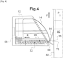
- the retractable bolt 78 while maintaining the stop member 14 away from the bearing face 28 of the housing, causes its retraction along the arrow R inside the housing 12, by compressing the helical spring 56, as shown in [ Fig. 4 ]. It will be observed that the front edge 30 of the stopping member 14 is then in sliding support against the docking face 84.
- the lock 80 continues its movement according to the arrow F.
- the ridge 88 of the retractable bolt 78 then joins the edge front 30 of the stop member 14 which is substantially parallel to it, and the retractable bolt 78 is then retracted to its maximum level. Then then, after the passage of the front edge 30, the retractable bolt 78 can escape the reach of the stopping member 14. And the leaf comes to bear against the elements of the frame which stop its movement.
- the stop member 14 also releases under the action of the helical spring 56 which relaxes. The stop member 14 is then driven towards the outside of the housing 12; and this, until the cylindrical flank 34 abuts against the cylindrical retaining surface 86 of the retractable bolt 78.
- the dimensions of the stopping member 14 and of the housing 12 allow a maximum amplitude of ejection of the stopping member 14, to adapt to the maximum relative deformations that the leaf and the frame can undergo.
- the force E is exerted by the retractable bolt 78 on the cylindrical flank 34 near the guide face 45 of the stopping member 14. And it is exerted towards the support face 28.
- the stopping member 14 is driven in translation inside the housing 12, and the flat side 32 comes to bear against the bearing face 28, while the plurality of hooking teeth 70 comes engaged in the plurality of retaining teeth 62. More precisely, the hooking sides 72 bear against the retaining sides 64.
- the stopping member 14 Since the joint plane between the hooking sides 72 and the retaining sides 64 is inclined in a direction close to a direction perpendicular to the bearing face 28, the stopping member 14 is perfectly blocked in translation in the direction of retraction. Furthermore, thanks to the pressure exerted by the leaf via the retractable bolt 78, the blocking of the stopping member 14 is ensured.
- the leaf is itself immobilized in the closed position thanks to the retractable bolt 78.
- the opening of the leaf can only be done by unlocking the lock 80 and therefore causing the retractable bolt 78 to pivot again towards the inside of the lock 80.
Landscapes
- Lock And Its Accessories (AREA)
- Preliminary Treatment Of Fibers (AREA)
- Seats For Vehicles (AREA)
Description
- La présente invention se rapporte à une gâche réglable pour un dormant apte à recevoir un battant équipé d'un mécanisme muni d'un pêne rétractable.
- Un domaine d'application envisagé est notamment, mais non exclusivement, celui des serrures anti-panique permettant d'ouvrir aisément sous la précipitation, un battant, soit une porte, de l'intérieur d'un bâtiment vers l'extérieur, lorsqu'il est verrouillé de l'extérieur vers l'intérieur. Aussi, de telles portes, dites « portes de secours », viennent refermer une ouverture délimitée par un dormant.
- Des gâches réglables connues comportent un boîtier présentant une face destinée à être appliquée contre le montant d'un dormant et à y être vissée. Les gâches comprennent en outre un organe d'arrêt sensiblement prismatique et monté réglable à l'intérieur du boîtier grâce a deux vis adaptées.
- L'organe d'arrêt présente une arête frontale et deux flancs opposés l'un de l'autre par rapport à cette arête frontale. Ainsi, l'un des flancs de l'organe d'arrêt est orienté vers l'intérieur, tandis que l'autre est orienté vers l'extérieur. Le dormant reçoit le battant monté articulé verticalement sur l'autre montant du dormant et à l'opposé de la gâche réglable. Et le battant est équipé d'un mécanisme de verrouillage muni d'un pêne rétractable adapté à coopérer avec la gâche.
- Le battant est par exemple rappelé par un ferme-porte et lorsque ce dernier l'entraîne en pivotement pour refermer l'ouverture, le pêne rétractable vient en butée contre l'un des flancs de l'organe d'arrêt et il se rétracte alors pour permettre au battant de poursuivre sa course et venir s'engager complètement à l'intérieur du dormant, alors que le pêne revient derrière l'organe d'arrêt pour venir en appui contre son flanc opposé. Le battant est alors maintenu en position fixe à l'intérieur du dormant.
- Aussi, la gâche, et plus précisément l'organe d'arrêt est réglable à l'intérieur du boîtier de manière à pouvoir ajuster précisément la position relative du pêne rétractable et de l'organe d'arrêt pour un verrouillage optimal. Ce réglage est réalisé au montage du battant dans le dormant et de la gâche. Et il peut également être réalisé lorsque le dormant et le battant évoluent au fil du temps et que leur position relative s'écarte de la position originelle. Cette évolution peut être due au vieillissement du bâtiment par exemple, à la dilatation ou à la fréquence des sollicitations. Et elle peut alors occasionner un défaut de verrouillage.
- Il peut alors être nécessaire de régler fréquemment l'organe d'arrêt, ce qui requiert de mettre en place une surveillance des gâches et en conséquence, entraîne des coûts.
- Le document
EP 0362040 B1 divulgue une gâche réglable de serrure pour volet, comprenant un boitier et un organe d'arrêt sous forme d'une barre comportant des dents qui est montée réglable à l'intérieur dudit boitier. La position du volet fermé, par rapport à une partie dormante comportant la gâche, est réglée en exerçant une poussée suffisante sur ce volet, ce qui provoque le déplacement de l'organe d'arrêt en translation suivant un déplacement pas-à-pas. - Partant, un problème qui se pose et que vise à résoudre la présente invention est de fournir une gâche réglable requérant moins de surveillance et par conséquent, qui soit moins coûteuse à exploiter, pour pouvoir obtenir la meilleure fermeture possible du battant dans le dormant.
- Dans ce but, il est proposé une gâche réglable comprenant un boîtier adapté à être monté sur un dormant, ledit dormant étant apte à recevoir un battant équipé d'un mécanisme muni d'un pêne rétractable ; et, un organe d'arrêt monté réglable à l'intérieur dudit boîtier, ledit organe d'arrêt présentant une arête frontale et deux flancs opposés l'un de l'autre par rapport à ladite arête frontale, l'un desdits flancs étant adapté à recevoir ledit pêne rétractable en butée pour provoquer la rétraction dudit pêne et autoriser l'engagement dudit battant à l'intérieur dudit dormant, tandis que ledit pêne revient en appui contre l'autre flanc desdits deux flancs pour pouvoir maintenir ledit battant en position fixe à l'intérieur dudit dormant. Ledit boîtier présente à l'intérieur une face d'appui munie de dents de retenue, tandis que ledit organe d'arrêt présente des dents d'accrochage s'étendant dans ledit un desdits flancs, et ledit organe d'arrêt est adapté à être rétracté à l'intérieur dudit boîtier lorsque ledit pêne vient en butée contre ledit un desdits flancs et à venir ensuite s'étendre dudit boîtier pour venir en contact avec ledit pêne, tandis que lesdites dents d'accrochage viennent en prise dans lesdites dents de retenue pour interdire la rétraction dudit organe d'arrêt lorsque ledit pêne prend appui contre ledit autre flanc.
- Ainsi, une caractéristique de l'invention réside dans la mise en oeuvre d'un organe d'arrêt auto-réglable. De la sorte, à chaque fois que le battant est engagé dans le dormant pour venir obturer l'ouverture dans laquelle est installé le dormant, l'organe d'arrêt vient s'ajuster dans une position optimale pour la retenue du pêne rétractable. Et ce, quelles que soient les évolutions dimensionnelles relatives du dormant et du battant au cours du temps et des sollicitations. Pour ce faire, ledit organe d'arrêt se rétracte à l'intérieur dudit boîtier lorsque ledit pêne vient l'accoster par l'un desdits flancs, tandis que le pêne rétractable, lui-même, se rétracte à l'intérieur de son mécanisme. Après que le pêne rétractable a franchi l'arête frontale, et que le battant vient dans son élan occuper sa position terminale d'obturation, le pêne rétractable se relâche. L'organe d'arrêt, se relâche également et vient alors coopérer avec le pêne rétractable de manière à ce que l'autre flanc vienne en contact avec le pêne rétractable. Le pêne rétractable vient alors, par l'intermédiaire du battant, exercer à l'inverse un effort sur l'autre flanc de l'organe d'arrêt. Cela provoque la mise en prise des dents d'accrochage et des dents de retenue et partant, le blocage de l'organe d'arrêt dans le sens de la rétraction.
- Par ailleurs, lorsque le pêne rétractable vient accoster l'organe d'arrêt, par ledit un desdits flancs, il tend par la même à écarter l'organe d'arrêt de la face d'appui du boîtier et par conséquent à désengager les dents d'accrochage des dents de retenue. La rétraction de l'organe d'arrêt dans le boîtier est alors autorisée.
- Ainsi, quelle que soit la position relative du pêne rétractable et de la gâche, lorsque le battant atteint sa position terminale d'obturation, l'organe d'arrêt vient s'étendre dans l'espace libre qui s'étend entre le boîtier et le pêne rétractable jusqu'à venir au contact de ce dernier. Et c'est grâce à cette caractéristique, que la gâche objet de l'invention est auto-réglable.
- On observera que ce type de gâche réglable peut être mise en oeuvre sur tout type de dormant accueillant des portes traditionnelles et pas seulement, pour les dispositifs anti-panique.
- Selon une caractéristique de l'invention, la gâche réglable comprend un ressort de rappel monté à l'intérieur dudit boîtier pour provoquer l'extension dudit organe d'arrêt. Ainsi, après que l'organe d'arrêt a été rétracté à l'intérieur du boîtier par le mouvement du pêne rétractable, il vient s'étendre en dehors du boîtier à l'inverse, grâce au ressort de rappel, dès lors qu'il échappe à la portée du pêne rétractable. Le ressort de rappel présente une raideur prédéterminée qu'il convient de définir en fonction de l'effort à fournir pour rétracter le pêne rétractable.
- Avantageusement, ledit boîtier comprend une face d'applique et un bord libre longeant ladite face d'applique et ladite face d'appui, et lesdites dents de retenue présentent une génératrice de retenue sensiblement parallèle audit bord libre. Aussi, comme on l'expliquera ci-après, l'organe d'arrêt est mobile en translation selon une direction perpendiculaire au bord libre et aux dents de retenue.
- En outre, lesdites dents de retenue présentent chacune un flanc de retenue orienté vers l'extérieur dudit boîtier, ledit flanc de retenue étant incliné selon un plan moyen voisin d'un plan perpendiculaire à ladite face d'appui. De la sorte, et comme on le comprendra mieux ci-après, les risques de rétraction intempestives de l'organe d'arrêt à l'intérieur du boîtier, lorsque le pêne rétractable est en appui contre lui, sont nuls.
- Aussi, lesdites dents de retenue présentent chacune un premier flanc de glissement opposé audit flanc de retenue, ledit premier flanc de glissement étant incliné d'un angle sensiblement droit par rapport audit flanc de retenue. Ainsi, les dents de retenue sont dissymétriques. Par ailleurs, une telle géométrie des premiers flancs de glissement permet de faciliter l'extension de l'organe d'arrêt vers l'extérieur du boîtier.
- Selon une caractéristique de réalisation de l'invention particulièrement avantageuse, lesdites dents d'accrochage présentent une génératrice d'accrochage sensiblement parallèle à ladite arête frontale. Ainsi, les dents d'accrochage s'étendent selon une direction parallèle à l'arête frontale et perpendiculaire à la direction de translation de l'organe d'arrêt. De la sorte, les dents d'accrochage viennent coopérer parfaitement avec les dents de retenue. Car en effet, les dents d'accrochage s'étendent selon une direction transversale commune aux dents de retenue.
- Préférentiellement, lesdites dents d'accrochage présentent chacune un flanc d'accrochage orienté à l'opposé de ladite arête frontale, ledit flanc d'accrochage étant incliné selon un plan moyen voisin d'un plan perpendiculaire audit un desdits flanc dudit organe d'arrêt. De la sorte, comme on l'expliquera plus en détail ci-après, le flanc d'accrochage des dents d'accrochage vient s'appliquer à plat contre le flanc de retenue des dents de retenue, et de surcroît le plan de joint entre les flancs d'accrochage et les flancs de retenue est proche de la perpendiculaire à la direction de translation de l'organe d'arrêt dans le boîtier. De la sorte, on obtient un meilleur blocage de l'organe d'arrêt vis-à-vis du boîtier lorsque les dents de retenue et les dents d'accrochage sont en prise les unes dans les autres.
- En outre, lesdites dents d'accrochage présentent chacune un second flanc de glissement opposé audit flanc d'accrochage, ledit second flanc de glissement étant incliné sensiblement selon un angle droit par rapport audit flanc d'accrochage. De la sorte, le premier flanc de glissement des dents de retenue vient coopérer avec le second flanc de glissement des dents d'accrochage lorsque l'organe d'arrêt est entraîné vers l'extérieur du boîtier. De la sorte, l'entraînement de l'organe d'arrêt est facilité. Aussi, durant ce mouvement, l'organe d'arrêt tend à s'écarter de la face d'appui. Par ailleurs, l'organe d'arrêt présente un jeu selon une direction perpendiculaire à la face d'appui du boîtier comme on l'expliquera ci-après.
- Selon une variante de réalisation de l'invention particulièrement avantageuse, ledit autre flanc dudit organe d'arrêt est de forme cylindrique définie par une génératrice parallèle à ladite arête frontale. De la sorte, on obtient un meilleur appui du pêne rétractable contre l'organe d'arrêt pour une meilleure coopération des dents d'accrochage et des dents de retenue.
- Aussi, ledit boîtier comprend des organes de guidage en translation dudit organe d'arrêt.
- D'autres particularités et avantages de l'invention ressortiront à la lecture de la description faite ci-après de modes de réalisation particuliers de l'invention, donnés à titre indicatif mais non limitatif, en référence aux dessins annexés sur lesquels :
- [
Fig. 1 ] est une vue schématique en perspective d'une gâche réglable conforme à l'invention ; - [
Fig. 2 ] est une vue schématique en coupe de l'objet de la [Fig. 1 ] selon le plan II-II ; - [
Fig. 3 ] est une vue schématique de côté et en transparence de l'objet de la [Fig. 1 ] selon la flèche III et d'un élément additionnel, dans une première position relative ; - [
Fig. 4 ] est une vue schématique de côté des éléments de la [Fig. 3 ] dans une deuxième position relative ; et, - [
Fig. 5 ] est une vue schématique de côté des éléments de la [Fig. 3 ] dans une troisième position relative. - La [
Fig. 1 ] montre une gâche réglable 10 comportant un boîtier 12 à l'intérieur duquel est installé un organe d'arrêt 14. Le boîtier 12 présente une paroi d'appui 16 opposée à une paroi longitudinale de recouvrement 18 sensiblement parallèle. La paroi longitudinale de recouvrement 18 est reliée à la paroi d'appui 16, par l'intermédiaire de deux parois trapézoïdales opposées inclinées 20, 22 et une paroi arrière 24, laquelle rejoint également les deux parois trapézoïdales opposées 20, 22. - Aussi, le boîtier 12 présente une ouverture 26 située en regard de la paroi arrière 24. L'ouverture 26 est délimitée notamment par un bord libre 25 de la paroi d'appui 16.
- Le boîtier 12 présente, à l'intérieur, une face d'appui 28 sur laquelle vient s'appuyer l'organe d'arrêt 14. Et la paroi d'appui 16 définit également une face d'applique 29, opposée à la face d'appui 28. La paroi d'appui 16 définit un plan moyen et la face d'appui 28 définit un autre plan moyen sensiblement parallèle au plan moyen de la paroi d'appui 16.
- Aussi, l'organe d'arrêt 14 présente une arête frontale 30 et d'un côté de l'arête frontale 30, un flanc plat 32, et de l'autre à l'opposé, un flanc cylindrique 34. Le flanc plat 32 se prolonge selon un même plan moyen, jusqu'à un talon 35 de l'organe d'arrêt 14.
- L'organe d'arrêt 14 présente également deux faces latérales opposées 36, 38. Les deux faces latérales opposées 36, 38 rejoignent une face de guidage 45, sensiblement parallèle au flanc plat 32 et qui s'étend dans le prolongement du flanc cylindrique 34.
- Aussi, l'organe d'arrêt 14 est maintenu entre deux ailes libres 40, 42 situées respectivement à équidistance des deux parois trapézoïdales 20, 22. Les deux ailes libres 40, 42 s'étendent à l'intérieur du boîtier 12 depuis la paroi longitudinale de recouvrement 18 et la paroi arrière 24.
- Aussi, les deux ailes libres 40, 42 présentent deux bords de guidage 44, 46 qui viennent s'étendre sensiblement à équidistance entre la paroi longitudinale de recouvrement 18 et la face d'appui 28 selon une direction sensiblement parallèle à la face d'appui 28.
- Par ailleurs, l'organe d'arrêt 14 comprend deux nervures latérales 48, 50 s'étendant en saillie des deux faces latérales opposées 36, 38. Les deux nervures latérales 48, 50 s'étendent sensiblement parallèlement au plan moyen précité défini par le flanc plat 32. Aussi, les deux nervures latérales 48, 50 sont adaptées à venir respectivement en appui glissant contre les bords de guidage 44, 46.
- On observera que l'organe d'arrêt 14 est mobile en translation à l'intérieur du boîtier 12 selon une direction perpendiculaire à la face d'appui 28 selon une faible amplitude que l'on précisera ensuite. Ainsi, lorsque les nervures latérales 48, 50 viennent en appui contre le bord de guidage 44, 46, le flanc plat 32 est sensiblement écarté de la face d'appui 28 du boîtier 12. Aussi, la face de guidage 45 est en appui glissant contre la paroi longitudinale de recouvrement 18 du boîtier 12.
- En outre, le boîtier 12 présente deux vis de fixation 52, 54 situées de chaque côté de l'organe d'arrêt 14 et qui s'étendent à travers la paroi d'appui 16. Le boîtier 12 est alors adapté à être relié au montant d'un dormant non représenté, la face d'applique 29 de la paroi d'appui 16 en applique contre le dormant et les deux vis de fixation 52, 54 vissées dans celui-ci.
- On se référera à présent sur la [
Fig. 2 ] pour décrire plus en détail le mode de coopération de l'organe d'arrêt 14 et du boîtier 12. - Tout d'abord, entre l'organe d'arrêt 14 et la paroi arrière 24 du boîtier 12, s'étend un ressort hélicoïdal, 56. Ce ressort hélicoïdal 56 s'étend dans un logement 58 ménagé dans le talon 35 de l'organe d'arrêt 14. Le logement 58, de forme cylindrique, s'étend à l'intérieur de l'organe d'arrêt 14 parallèlement au flanc plat 32 selon une direction sensiblement perpendiculaire à l'arête frontale 30.
- Le logement 58 présente une paroi d'arrêt 60 inclinée par rapport au flanc plat 32 et contre laquelle vient s'appliquer le ressort hélicoïdal 56. Plus précisément, la paroi d'arrêt 60 présente une normale qui vient couper le flanc cylindrique 34. Ainsi, le ressort hélicoïdal 56 tend à repousser l'organe d'arrêt 14 vers l'extérieur du boîtier 12. De surcroît, grâce à la paroi d'arrêt inclinée 60, laquelle forme rampe en coopérant avec le ressort hélicoïdal 56, l'organe d'arrêt 14 tend à être écarté sensiblement de la face d'appui 28, comme on va l'expliquer ci-dessous.
- Aussi, la face d'appui 28 comporte une pluralité de dents de retenue 62. Et les dents de retenue 62 sont définies par une génératrice qui s'étend sensiblement parallèlement au bord libre 25 de la paroi d'appui 16. Chacune des dents de retenue 62 présente un flanc de retenue 64 orienté vers l'extérieur du boîtier, et un premier flanc de glissement 66, sensiblement perpendiculaire au flanc de retenue 64. Le flanc de retenue 64 et le premier flanc de glissement 66 se rejoignent à un sommet de retenue 68. Le flanc de retenue 64 est incliné selon un plan moyen proche d'un plan perpendiculaire à la face d'appui 28. Aussi, les dents de retenue 62 de ladite pluralité de dents sont identiques.
- En outre, et en regard, le flanc plat 32 de l'organe d'arrêt 14, présente une pluralité de dents d'accrochage 70, définies par une génératrice sensiblement parallèle à l'arête frontale 30. Chacune des dents d'accrochage 70 présente un flanc d'accrochage 72 orienté à l'opposé de l'arête frontale 30, et un second flanc de glissement 74 opposé au flanc d'accrochage 72. Le flanc d'accrochage 72 et le second flanc de glissement 74 se rejoignent à un sommet d'accrochage 76. Aussi, le flanc d'accrochage 72 est incliné selon un plan moyen proche d'un plan perpendiculaire au flanc plat 32. Et le second flanc de glissement 74 est sensiblement perpendiculaire au flanc d'accrochage 72.
- En outre, les dents d'accrochage 70 de la pluralité de dents d'accrochage, sont également identiques.
- Par ailleurs, les dents d'accrochage 70 et des dents de retenue 62 présentent une géométrie et des dimensions identiques de manière à pouvoir s'interpénétrer les unes dans les autres comme on va l'expliquer ci-après.
- On se référera à présent à la [
Fig. 3 ] pour décrire en détail le mode de fonctionnement de la gâche réglable 10 en coopération avec un pêne rétractable 78 d'une serrure 80 installée sur un battant non représenté. Le battant est destiné à isoler un intérieur 81, vis-à-vis d'un extérieur 83. - La gâche réglable 10 est, elle, installée à l'intérieur 81 sur le dormant correspondant et non représenté non plus. On retrouve sur la [
Fig. 3 ] l'organe d'arrêt 14 en extension en dehors du boîtier 10. - Quant au pêne rétractable 78, il vient s'étendre en saillie d'une têtière 82 et il est monté pivotant autour d'un axe de pivotement P situé à l'intérieur de la serrure 80. Tel que représenté sur la [
Fig. 3 ], le pêne rétractable 78 est dans sa position de repos et d'extension maximale en dehors de la serrure 80. Autrement dit, il est bloqué en rotation dans le sens des aiguilles d'une montre. - En outre, l'axe de pivotement P du pêne rétractable 78 est orienté selon une direction sensiblement parallèle à l'axe de pivotement du battant.
- Aussi, le pêne rétractable 78 présente une face d'accostage 84 et à l'opposé, une surface de retenue cylindrique 86. La face d'accostage 84 et la surface de retenue cylindrique 86 se rejoignent au niveau d'une crête 88. Le pêne rétractable 78 est sur la [
Fig. 3 ] au repos, et la face d'accostage 84 est inclinée par rapport à la têtière 82 d'environ 135°. Et la surface de retenue cylindrique 86 rejoint la face d'accostage 84 au niveau de la crête 88 sensiblement à 90°. - Ainsi, lorsque le battant pivote, la serrure 80 et par conséquent le pêne rétractable 78 pivotent également, et le pêne rétractable 78 est entraîné suivant une trajectoire sensiblement rectiligne selon la flèche F, compte tenu de la distance qui s'étend entre la serrure 80 et l'axe de pivotement du battant.
- Partant, la face d'accostage 84 du pêne rétractable 78 va venir en butée contre le flanc plat 32 de l'organe d'arrêt 14, au voisinage de l'arête frontale 30. En conséquence, l'organe d'arrêt 14 est d'abord entraîné en mouvement par rapport au boîtier 12, selon une composante perpendiculaire à la face d'appui 28 du boîtier, de sorte que les nervures 48, 50 de l'organe d'arrêt 14 telles qu'illustrées sur la [
Fig. 1 ] viennent s'appuyer contre le bord de guidage 44, 46 des deux ailes libres 40, 42. De la sorte, le flanc plat 32 de l'organe d'arrêt 14 s'écarte de la face d'appui 28, et la pluralité de dents d'accrochage 70 échappe à la portée de la pluralité de dents de retenue 62. - On observera que l'amplitude maximale du mouvement de l'organe d'arrêt 14 selon ladite composante perpendiculaire à la face d'appui 28, est sensiblement supérieure à la hauteur des dents de retenue 62 et des dents d'accrochage 70.
- Partant, le battant en poursuivant sa course, provoque également le pivotement du pêne rétractable 78 vers l'intérieur de la serrure 80 autour de l'axe de pivotement P.
- Conséquemment, le pêne rétractable 78, tout en maintenant l'organe d'arrêt 14 écarté de la face d'appui 28 du boîtier, provoque sa rétraction selon la flèche R à l'intérieur du boîtier 12, en comprimant le ressort hélicoïdal 56, comme illustré sur la [
Fig. 4 ]. On observera que l'arête frontale 30 de l'organe d'arrêt 14 est alors en appui glissant contre la face d'accostage 84. - Aussi, si le pêne rétractable 78 provoque la rétraction de l'organe d'arrêt 14 à l'intérieur du boîtier 12, à l'inverse, l'organe d'arrêt 14 induit la rétraction du pêne rétractable en pivotement à l'intérieur de la serrure 80.
- Ensuite, le battant poursuivant sa course, la serrure 80 poursuit son mouvement selon la flèche F. La crête 88 du pêne rétractable 78 rejoint alors l'arête frontale 30 de l'organe d'arrêt 14 qui lui est sensiblement parallèle, et le pêne rétractable 78 est alors rétracté à son niveau maximal. Puis ensuite, après le passage de l'arête frontale 30, le pêne rétractable 78 peut échapper à la portée de l'organe d'arrêt 14. Et le battant vient en appui contre les éléments du dormant qui viennent stopper sa course.
- Aussi, dès que le pêne rétractable 78 se relâche pour retrouver sa position de repos, alors l'organe d'arrêt 14 se relâche également sous l'action du ressort hélicoïdal 56 qui se détend. L'organe d'arrêt 14 est alors entraîné en mouvement vers l'extérieur du boîtier 12 ; et ce, jusqu'à ce que le flanc cylindrique 34 vienne en butée contre la surface de retenue cylindrique 86 du pêne rétractable 78.
- On observera que les dimensions de l'organe d'arrêt 14 et du boîtier 12 permettent une amplitude maximale d'éjection de l'organe d'arrêt 14, pour s'adapter aux déformations relatives maximales que peuvent subir le battant et le dormant.
- Cette éjection de l'organe d'arrêt 14, par l'intermédiaire du ressort hélicoïdal 56, est autorisée, car le flanc plat 32 demeure écarté de la face d'appui 28. Par conséquent, la pluralité de dents d'accrochage 70 n'interfère pas avec la pluralité de dents de retenue 62.
- Néanmoins, s'il y avait une interférence, compte tenu de l'inclinaison respective des premiers flancs de glissement 66 et des seconds flans de glissement 74, respectivement des dents de retenue 62 et des dents d'accrochage 70, dont le plan de joint serait faiblement incliné par rapport au mouvement de translation de l'organe d'arrêt 14 vers l'extérieur du boîtier 12, le mouvement de l'organe d'arrêt 14 ne serait pas entravé.
- En revanche, et comme illustré sur la [
Fig. 5 ], dès lors que le pêne rétractable 78 a retrouvé sa position de repos en extension de la serrure 80, et qu'il est bloqué en rotation dans le sens horaire, tandis que le battant est en butée, et que l'organe d'arrêt 14 est étendu du boîtier 12 de sorte que son flanc cylindrique 34 est en butée contre la surface de retenue cylindrique 86 du pêne rétractable 78, en retour, le pêne rétractable vient exercer par l'intermédiaire du battant, un effort selon la flèche E contre l'organe d'arrêt 14. L'effort est ainsi orienté selon une direction voisine de la perpendiculaire à la face d'appui 28, et vers cette dernière. - L'effort E est exercé par le pêne rétractable 78 sur le flanc cylindrique 34 près de la face de guidage 45 de l'organe d'arrêt 14. Et il s'exerce vers la face d'appui 28. De la sorte, l'organe d'arrêt 14 est entraîné en translation à l'intérieur du boîtier 12, et le flanc plat 32 vient en appui contre la face d'appui 28, tandis que la pluralité de dents d'accrochage 70 vient en prise dans la pluralité de dents de retenue 62. Plus précisément, les flancs d'accrochage 72 viennent en appui contre les flancs de retenue 64.
- Puisque le plan de joint entre les flancs d'accrochage 72 et les flancs de retenue 64 est incliné selon une direction proche d'une direction perpendiculaire à la face d'appui 28, l'organe d'arrêt 14 est parfaitement bloqué en translation dans le sens de la rétraction. Au surplus, grâce à la pression exercée par le battant par l'intermédiaire du pêne rétractable 78, le blocage de l'organe d'arrêt 14 est assuré.
- Partant, le battant est lui-même immobilisé en position de fermeture grâce au pêne rétractable 78.
- Dans la position relative des éléments représentés sur la [
Fig. 5 ], l'ouverture du battant ne peut se faire qu'en déverrouillant la serrure 80 et partant, en provoquant à nouveau le pivotement du pêne rétractable 78 vers l'intérieur de la serrure 80. - Ainsi, si avec le temps ou bien au fil des ouvertures et fermetures, le boîtier 12 et la serrure 80 venaient à s'écarter l'un de l'autre, alors l'excursion de l'organe d'arrêt 14 se ferait avec une plus grande amplitude et la qualité du verrouillage demeurerait.
- À l'inverse, si le boîtier 12 et la serrure 80 venaient à se rapprocher l'un de l'autre, alors l'excursion de l'organe d'arrêt 14 se ferait avec une moins grande amplitude et la qualité du verrouillage serait conservée.
Claims (9)
- Gâche réglable comprenant :- un boîtier (12) adapté à être monté sur un dormant, ledit dormant étant apte à recevoir un battant équipé d'un mécanisme (80) muni d'un pêne rétractable (78) ;- un organe d'arrêt (14) monté réglable à l'intérieur dudit boîtier (12), ledit organe d'arrêt (14) présentant une arête frontale (30) et deux flancs (32, 34) opposés l'un de l'autre par rapport à ladite arête frontale (30), l'un (32) desdits flancs étant adapté à recevoir ledit pêne rétractable (78) en butée pour provoquer la rétraction dudit pêne et autoriser l'engagement dudit battant à l'intérieur dudit dormant, tandis que ledit pêne (78) revient en appui contre l'autre (34) flanc desdits deux flancs pour pouvoir maintenir ledit battant en position fixe à l'intérieur dudit dormant ; etledit boîtier (12) présentant à l'intérieur une face d'appui (28) munie de dents de retenue (62), tandis que ledit organe d'arrêt (14) présente des dents d'accrochage (70) s'étendant dans ledit un (32) desdits flancs,et ledit organe d'arrêt (14) étant adapté à être rétracté à l'intérieur dudit boîtier (12) lorsque ledit pêne (78) vient en butée contre ledit un (32) desdits flancs et à venir ensuite s'étendre dudit boîtier (12) pour venir en contact avec ledit pêne (78), tandis que lesdites dents d'accrochage (70) viennent en prise dans lesdites dents de retenue (62) pour interdire la rétraction dudit organe d'arrêt (14) lorsque ledit pêne (78) prend appui contre ledit autre flanc (34), et ladite gâche comprenant un ressort de rappel (56) monté à l'intérieur dudit boîtier (12) pour provoquer l'extension dudit organe d'arrêt (14).
- Gâche réglable selon la revendication 1, caractérisée en ce que ledit boîtier (12) comprend une face d'applique (29) et un bord libre (25) longeant ladite face d'applique (29) et ladite face d'appui (28), et en ce que lesdites dents de retenue (62) présentent une génératrice de retenue sensiblement parallèle audit bord libre (25).
- Gâche réglable selon l'une quelconque des revendications 1 à 2, caractérisée en ce que lesdites dents de retenue (62) présentent chacune un flanc de retenue (64) orienté vers l'extérieur dudit boîtier (12), ledit flanc de retenue (64) étant incliné selon un plan moyen voisin d'un plan perpendiculaire à ladite face d'appui (28).
- Gâche réglable selon la revendication 3, caractérisée en ce que lesdites dents de retenue (62) présentent chacune un premier flanc de glissement (66) opposé audit flanc de retenue (64), ledit premier flanc de glissement (66) étant incliné d'un angle sensiblement droit par rapport audit flanc de retenue (64).
- Gâche réglable selon l'une quelconque des revendications 1 à 4, caractérisée en ce que lesdites dents d'accrochage (70) présentent une génératrice d'accrochage sensiblement parallèle à ladite arête frontale (30).
- Gâche réglable selon l'une quelconque des revendications 1 à 5, caractérisée en ce que lesdites dents d'accrochage (70) présentent chacune un flanc d'accrochage (72) orienté à l'opposé de ladite arête frontale (30), ledit flanc d'accrochage (72) étant incliné selon un plan moyen voisin d'un plan perpendiculaire audit un desdits flanc (32) dudit organe d'arrêt (14).
- Gâche réglable selon la revendication 6, caractérisée en ce que lesdites dents d'accrochage (70) présentent chacune un second flanc de glissement (74) opposé audit flanc d'accrochage (72), ledit second flanc de glissement (74) étant incliné sensiblement selon un angle droit par rapport audit flanc d'accrochage (72).
- Gâche réglable selon l'une quelconque des revendications 1 à 7, caractérisée en ce que ledit autre flanc (34) dudit organe d'arrêt (14) est de forme cylindrique définie par une génératrice parallèle à ladite arête frontale (30).
- Gâche réglable selon l'une quelconque des revendications 1 à 8, caractérisée en ce que ledit boîtier (12) comprend des organes de guidage (40, 42) en translation dudit organe d'arrêt (14).
Priority Applications (1)
| Application Number | Priority Date | Filing Date | Title |
|---|---|---|---|
| MA62470A MA62470B1 (fr) | 2021-08-31 | 2022-08-31 | Gâche réglable |
Applications Claiming Priority (1)
| Application Number | Priority Date | Filing Date | Title |
|---|---|---|---|
| FR2109079A FR3126437B1 (fr) | 2021-08-31 | 2021-08-31 | Gâche réglable |
Publications (2)
| Publication Number | Publication Date |
|---|---|
| EP4144941A1 EP4144941A1 (fr) | 2023-03-08 |
| EP4144941B1 true EP4144941B1 (fr) | 2024-08-07 |
Family
ID=78049407
Family Applications (1)
| Application Number | Title | Priority Date | Filing Date |
|---|---|---|---|
| EP22193210.6A Active EP4144941B1 (fr) | 2021-08-31 | 2022-08-31 | Gâche réglable |
Country Status (6)
| Country | Link |
|---|---|
| EP (1) | EP4144941B1 (fr) |
| ES (1) | ES2991792T3 (fr) |
| FR (1) | FR3126437B1 (fr) |
| MA (1) | MA62470B1 (fr) |
| PL (1) | PL4144941T3 (fr) |
| PT (1) | PT4144941T (fr) |
Family Cites Families (4)
| Publication number | Priority date | Publication date | Assignee | Title |
|---|---|---|---|---|
| US2904367A (en) * | 1957-04-23 | 1959-09-15 | Bennett Patrick John | Door latch device |
| NL8701748A (nl) * | 1987-07-23 | 1989-02-16 | Buva Bv | Sluitplaat. |
| FR2637002B1 (fr) * | 1988-09-26 | 1990-11-30 | Vachette Sa | Gache reglable de serrure, en particulier pour volet ou portiere de vehicule automobile, et serrure comportant une telle gache |
| DE102007018871B4 (de) * | 2006-05-15 | 2020-04-09 | Kfv Karl Fliether Gmbh & Co. Kg | Gegenschließteil mit schwenkbarer Sperrplatte |
-
2021
- 2021-08-31 FR FR2109079A patent/FR3126437B1/fr active Active
-
2022
- 2022-08-31 EP EP22193210.6A patent/EP4144941B1/fr active Active
- 2022-08-31 MA MA62470A patent/MA62470B1/fr unknown
- 2022-08-31 PL PL22193210.6T patent/PL4144941T3/pl unknown
- 2022-08-31 PT PT221932106T patent/PT4144941T/pt unknown
- 2022-08-31 ES ES22193210T patent/ES2991792T3/es active Active
Also Published As
| Publication number | Publication date |
|---|---|
| FR3126437B1 (fr) | 2023-11-24 |
| EP4144941A1 (fr) | 2023-03-08 |
| PT4144941T (pt) | 2024-10-02 |
| PL4144941T3 (pl) | 2024-12-16 |
| FR3126437A1 (fr) | 2023-03-03 |
| ES2991792T3 (es) | 2024-12-04 |
| MA62470B1 (fr) | 2024-09-30 |
Similar Documents
| Publication | Publication Date | Title |
|---|---|---|
| EP2650460A2 (fr) | Dispositif de fermeture provisoire d'un élément ouvrant sur un élément support | |
| EP4190998A1 (fr) | Dispositif de maintien d'un vantail | |
| EP2415954B1 (fr) | Ferrure en applique comportant une bride de fixation | |
| EP0801196A1 (fr) | Elément de ferrure pour porte, fenêtre ou analogue, notamment une gâche, destiné à être monté sur un profilé en aluminium ou pvc | |
| EP4144941A1 (fr) | Gâche réglable | |
| EP1880072B1 (fr) | Serrure a deux positions de blocage longitudinalement decalees | |
| EP0504044B1 (fr) | Armoire à porte verrouillable et retournable, et système comportant une telle armoire | |
| FR2927644A1 (fr) | Pene demi-tour a organe de contact | |
| EP1808557B1 (fr) | Ferrure de verrouillage | |
| EP1808560B1 (fr) | Dispositif de fermeture de coffret | |
| FR2792362A1 (fr) | Volet roulant comprenant un arbre d'enroulement maintenu par des equerres de fixation | |
| EP3530851B1 (fr) | Système de verrouillage pour une porte sectionnelle à déplacement latéral | |
| FR2699588A1 (fr) | Bloc-porte à montage réversible avec ouverture à droite ou à gauche. | |
| FR2926579A1 (fr) | Serrure de securite renforcee | |
| EP2907947B1 (fr) | Dispositif de verrouillage pour vantail semi-fixe de porte ou fenêtre | |
| EP1475497A1 (fr) | Verrou d'immobilisation pour vantail de porte ou fenêtre | |
| FR2786527A1 (fr) | Dispositif de relevage pour chassis ouvrant de porte, fenetre ou analogue | |
| EP2345785A1 (fr) | Arrêt de vantail | |
| FR3161701A1 (fr) | Dispositif d’ouverture et de fermeture d’une serrure multipoints | |
| EP0805250B1 (fr) | Entrebâilleur pour fenêtre, porte-fenêtre ou analogue | |
| FR2696051A1 (fr) | Armoire à battant de porte équipé d'un détecteur de fermeture. | |
| EP0600785B1 (fr) | Boîtier à verrouillage notamment pour appareil téléphonique public | |
| FR2633968A1 (fr) | Dispositif de fixation et de verrouillage automatique pour barres de securite sur des elements de fermetures du type volets, persiennes, portes et similaires | |
| FR3102435A1 (fr) | Véhicule automobile utilitaire muni d’une cloison de séparation transversale à porte pivotante | |
| EP4105419A1 (fr) | Dispositif perfectionne de fermeture provisoire d'un element ouvrant sur un element de support |
Legal Events
| Date | Code | Title | Description |
|---|---|---|---|
| PUAI | Public reference made under article 153(3) epc to a published international application that has entered the european phase |
Free format text: ORIGINAL CODE: 0009012 |
|
| STAA | Information on the status of an ep patent application or granted ep patent |
Free format text: STATUS: THE APPLICATION HAS BEEN PUBLISHED |
|
| AK | Designated contracting states |
Kind code of ref document: A1 Designated state(s): AL AT BE BG CH CY CZ DE DK EE ES FI FR GB GR HR HU IE IS IT LI LT LU LV MC MK MT NL NO PL PT RO RS SE SI SK SM TR |
|
| STAA | Information on the status of an ep patent application or granted ep patent |
Free format text: STATUS: REQUEST FOR EXAMINATION WAS MADE |
|
| 17P | Request for examination filed |
Effective date: 20230904 |
|
| RAV | Requested validation state of the european patent: fee paid |
Extension state: MA Effective date: 20230904 |
|
| RBV | Designated contracting states (corrected) |
Designated state(s): AL AT BE BG CH CY CZ DE DK EE ES FI FR GB GR HR HU IE IS IT LI LT LU LV MC MK MT NL NO PL PT RO RS SE SI SK SM TR |
|
| GRAP | Despatch of communication of intention to grant a patent |
Free format text: ORIGINAL CODE: EPIDOSNIGR1 |
|
| STAA | Information on the status of an ep patent application or granted ep patent |
Free format text: STATUS: GRANT OF PATENT IS INTENDED |
|
| INTG | Intention to grant announced |
Effective date: 20240311 |
|
| GRAS | Grant fee paid |
Free format text: ORIGINAL CODE: EPIDOSNIGR3 |
|
| GRAA | (expected) grant |
Free format text: ORIGINAL CODE: 0009210 |
|
| STAA | Information on the status of an ep patent application or granted ep patent |
Free format text: STATUS: THE PATENT HAS BEEN GRANTED |
|
| AK | Designated contracting states |
Kind code of ref document: B1 Designated state(s): AL AT BE BG CH CY CZ DE DK EE ES FI FR GB GR HR HU IE IS IT LI LT LU LV MC MK MT NL NO PL PT RO RS SE SI SK SM TR |
|
| REG | Reference to a national code |
Ref country code: GB Ref legal event code: FG4D Free format text: NOT ENGLISH |
|
| REG | Reference to a national code |
Ref country code: CH Ref legal event code: EP |
|
| REG | Reference to a national code |
Ref country code: IE Ref legal event code: FG4D Free format text: LANGUAGE OF EP DOCUMENT: FRENCH |
|
| REG | Reference to a national code |
Ref country code: DE Ref legal event code: R096 Ref document number: 602022005127 Country of ref document: DE |
|
| REG | Reference to a national code |
Ref country code: MA Ref legal event code: VAGR Ref document number: 62470 Country of ref document: MA Kind code of ref document: B1 |
|
| REG | Reference to a national code |
Ref country code: PT Ref legal event code: SC4A Ref document number: 4144941 Country of ref document: PT Date of ref document: 20241002 Kind code of ref document: T Free format text: AVAILABILITY OF NATIONAL TRANSLATION Effective date: 20240926 |
|
| P01 | Opt-out of the competence of the unified patent court (upc) registered |
Free format text: CASE NUMBER: APP_49448/2024 Effective date: 20240830 |
|
| REG | Reference to a national code |
Ref country code: LT Ref legal event code: MG9D |
|
| REG | Reference to a national code |
Ref country code: ES Ref legal event code: FG2A Ref document number: 2991792 Country of ref document: ES Kind code of ref document: T3 Effective date: 20241204 |
|
| REG | Reference to a national code |
Ref country code: NL Ref legal event code: MP Effective date: 20240807 |
|
| PG25 | Lapsed in a contracting state [announced via postgrant information from national office to epo] |
Ref country code: NO Free format text: LAPSE BECAUSE OF FAILURE TO SUBMIT A TRANSLATION OF THE DESCRIPTION OR TO PAY THE FEE WITHIN THE PRESCRIBED TIME-LIMIT Effective date: 20241107 |
|
| REG | Reference to a national code |
Ref country code: AT Ref legal event code: MK05 Ref document number: 1711098 Country of ref document: AT Kind code of ref document: T Effective date: 20240807 |
|
| PG25 | Lapsed in a contracting state [announced via postgrant information from national office to epo] |
Ref country code: GR Free format text: LAPSE BECAUSE OF FAILURE TO SUBMIT A TRANSLATION OF THE DESCRIPTION OR TO PAY THE FEE WITHIN THE PRESCRIBED TIME-LIMIT Effective date: 20241108 Ref country code: FI Free format text: LAPSE BECAUSE OF FAILURE TO SUBMIT A TRANSLATION OF THE DESCRIPTION OR TO PAY THE FEE WITHIN THE PRESCRIBED TIME-LIMIT Effective date: 20240807 Ref country code: NL Free format text: LAPSE BECAUSE OF FAILURE TO SUBMIT A TRANSLATION OF THE DESCRIPTION OR TO PAY THE FEE WITHIN THE PRESCRIBED TIME-LIMIT Effective date: 20240807 |
|
| PG25 | Lapsed in a contracting state [announced via postgrant information from national office to epo] |
Ref country code: BG Free format text: LAPSE BECAUSE OF FAILURE TO SUBMIT A TRANSLATION OF THE DESCRIPTION OR TO PAY THE FEE WITHIN THE PRESCRIBED TIME-LIMIT Effective date: 20240807 |
|
| PG25 | Lapsed in a contracting state [announced via postgrant information from national office to epo] |
Ref country code: LV Free format text: LAPSE BECAUSE OF FAILURE TO SUBMIT A TRANSLATION OF THE DESCRIPTION OR TO PAY THE FEE WITHIN THE PRESCRIBED TIME-LIMIT Effective date: 20240807 |
|
| PG25 | Lapsed in a contracting state [announced via postgrant information from national office to epo] |
Ref country code: AT Free format text: LAPSE BECAUSE OF FAILURE TO SUBMIT A TRANSLATION OF THE DESCRIPTION OR TO PAY THE FEE WITHIN THE PRESCRIBED TIME-LIMIT Effective date: 20240807 Ref country code: IS Free format text: LAPSE BECAUSE OF FAILURE TO SUBMIT A TRANSLATION OF THE DESCRIPTION OR TO PAY THE FEE WITHIN THE PRESCRIBED TIME-LIMIT Effective date: 20241207 |
|
| PG25 | Lapsed in a contracting state [announced via postgrant information from national office to epo] |
Ref country code: HR Free format text: LAPSE BECAUSE OF FAILURE TO SUBMIT A TRANSLATION OF THE DESCRIPTION OR TO PAY THE FEE WITHIN THE PRESCRIBED TIME-LIMIT Effective date: 20240807 |
|
| PG25 | Lapsed in a contracting state [announced via postgrant information from national office to epo] |
Ref country code: RS Free format text: LAPSE BECAUSE OF FAILURE TO SUBMIT A TRANSLATION OF THE DESCRIPTION OR TO PAY THE FEE WITHIN THE PRESCRIBED TIME-LIMIT Effective date: 20241107 |
|
| PG25 | Lapsed in a contracting state [announced via postgrant information from national office to epo] |
Ref country code: RS Free format text: LAPSE BECAUSE OF FAILURE TO SUBMIT A TRANSLATION OF THE DESCRIPTION OR TO PAY THE FEE WITHIN THE PRESCRIBED TIME-LIMIT Effective date: 20241107 Ref country code: NO Free format text: LAPSE BECAUSE OF FAILURE TO SUBMIT A TRANSLATION OF THE DESCRIPTION OR TO PAY THE FEE WITHIN THE PRESCRIBED TIME-LIMIT Effective date: 20241107 Ref country code: NL Free format text: LAPSE BECAUSE OF FAILURE TO SUBMIT A TRANSLATION OF THE DESCRIPTION OR TO PAY THE FEE WITHIN THE PRESCRIBED TIME-LIMIT Effective date: 20240807 Ref country code: LV Free format text: LAPSE BECAUSE OF FAILURE TO SUBMIT A TRANSLATION OF THE DESCRIPTION OR TO PAY THE FEE WITHIN THE PRESCRIBED TIME-LIMIT Effective date: 20240807 Ref country code: IS Free format text: LAPSE BECAUSE OF FAILURE TO SUBMIT A TRANSLATION OF THE DESCRIPTION OR TO PAY THE FEE WITHIN THE PRESCRIBED TIME-LIMIT Effective date: 20241207 Ref country code: HR Free format text: LAPSE BECAUSE OF FAILURE TO SUBMIT A TRANSLATION OF THE DESCRIPTION OR TO PAY THE FEE WITHIN THE PRESCRIBED TIME-LIMIT Effective date: 20240807 Ref country code: GR Free format text: LAPSE BECAUSE OF FAILURE TO SUBMIT A TRANSLATION OF THE DESCRIPTION OR TO PAY THE FEE WITHIN THE PRESCRIBED TIME-LIMIT Effective date: 20241108 Ref country code: FI Free format text: LAPSE BECAUSE OF FAILURE TO SUBMIT A TRANSLATION OF THE DESCRIPTION OR TO PAY THE FEE WITHIN THE PRESCRIBED TIME-LIMIT Effective date: 20240807 Ref country code: BG Free format text: LAPSE BECAUSE OF FAILURE TO SUBMIT A TRANSLATION OF THE DESCRIPTION OR TO PAY THE FEE WITHIN THE PRESCRIBED TIME-LIMIT Effective date: 20240807 Ref country code: AT Free format text: LAPSE BECAUSE OF FAILURE TO SUBMIT A TRANSLATION OF THE DESCRIPTION OR TO PAY THE FEE WITHIN THE PRESCRIBED TIME-LIMIT Effective date: 20240807 |
|
| PG25 | Lapsed in a contracting state [announced via postgrant information from national office to epo] |
Ref country code: SM Free format text: LAPSE BECAUSE OF FAILURE TO SUBMIT A TRANSLATION OF THE DESCRIPTION OR TO PAY THE FEE WITHIN THE PRESCRIBED TIME-LIMIT Effective date: 20240807 Ref country code: DK Free format text: LAPSE BECAUSE OF FAILURE TO SUBMIT A TRANSLATION OF THE DESCRIPTION OR TO PAY THE FEE WITHIN THE PRESCRIBED TIME-LIMIT Effective date: 20240807 |
|
| PG25 | Lapsed in a contracting state [announced via postgrant information from national office to epo] |
Ref country code: LU Free format text: LAPSE BECAUSE OF NON-PAYMENT OF DUE FEES Effective date: 20240831 |
|
| PG25 | Lapsed in a contracting state [announced via postgrant information from national office to epo] |
Ref country code: EE Free format text: LAPSE BECAUSE OF FAILURE TO SUBMIT A TRANSLATION OF THE DESCRIPTION OR TO PAY THE FEE WITHIN THE PRESCRIBED TIME-LIMIT Effective date: 20240807 |
|
| PG25 | Lapsed in a contracting state [announced via postgrant information from national office to epo] |
Ref country code: CZ Free format text: LAPSE BECAUSE OF FAILURE TO SUBMIT A TRANSLATION OF THE DESCRIPTION OR TO PAY THE FEE WITHIN THE PRESCRIBED TIME-LIMIT Effective date: 20240807 |
|
| PG25 | Lapsed in a contracting state [announced via postgrant information from national office to epo] |
Ref country code: SK Free format text: LAPSE BECAUSE OF FAILURE TO SUBMIT A TRANSLATION OF THE DESCRIPTION OR TO PAY THE FEE WITHIN THE PRESCRIBED TIME-LIMIT Effective date: 20240807 |
|
| REG | Reference to a national code |
Ref country code: DE Ref legal event code: R097 Ref document number: 602022005127 Country of ref document: DE |
|
| PLBE | No opposition filed within time limit |
Free format text: ORIGINAL CODE: 0009261 |
|
| STAA | Information on the status of an ep patent application or granted ep patent |
Free format text: STATUS: NO OPPOSITION FILED WITHIN TIME LIMIT |
|
| PG25 | Lapsed in a contracting state [announced via postgrant information from national office to epo] |
Ref country code: MC Free format text: LAPSE BECAUSE OF FAILURE TO SUBMIT A TRANSLATION OF THE DESCRIPTION OR TO PAY THE FEE WITHIN THE PRESCRIBED TIME-LIMIT Effective date: 20240807 |
|
| 26N | No opposition filed |
Effective date: 20250508 |
|
| PGFP | Annual fee paid to national office [announced via postgrant information from national office to epo] |
Ref country code: FR Payment date: 20250526 Year of fee payment: 4 |
|
| PG25 | Lapsed in a contracting state [announced via postgrant information from national office to epo] |
Ref country code: SE Free format text: LAPSE BECAUSE OF FAILURE TO SUBMIT A TRANSLATION OF THE DESCRIPTION OR TO PAY THE FEE WITHIN THE PRESCRIBED TIME-LIMIT Effective date: 20240807 |
|
| PGFP | Annual fee paid to national office [announced via postgrant information from national office to epo] |
Ref country code: ES Payment date: 20250926 Year of fee payment: 4 Ref country code: PT Payment date: 20250821 Year of fee payment: 4 |
|
| PGFP | Annual fee paid to national office [announced via postgrant information from national office to epo] |
Ref country code: DE Payment date: 20250820 Year of fee payment: 4 |
|
| PGFP | Annual fee paid to national office [announced via postgrant information from national office to epo] |
Ref country code: PL Payment date: 20250821 Year of fee payment: 4 |
|
| PGFP | Annual fee paid to national office [announced via postgrant information from national office to epo] |
Ref country code: BE Payment date: 20250820 Year of fee payment: 4 |
|
| PGFP | Annual fee paid to national office [announced via postgrant information from national office to epo] |
Ref country code: CH Payment date: 20250916 Year of fee payment: 4 |
|
| PGFP | Annual fee paid to national office [announced via postgrant information from national office to epo] |
Ref country code: IE Payment date: 20250820 Year of fee payment: 4 |
|
| PG25 | Lapsed in a contracting state [announced via postgrant information from national office to epo] |
Ref country code: RO Free format text: LAPSE BECAUSE OF FAILURE TO SUBMIT A TRANSLATION OF THE DESCRIPTION OR TO PAY THE FEE WITHIN THE PRESCRIBED TIME-LIMIT Effective date: 20240807 |
|
| VSFP | Annual fee paid to validation state [announced via postgrant information from national office to epo] |
Ref country code: MA Payment date: 20250819 Year of fee payment: 4 Ref country code: MA Payment date: 20240919 Year of fee payment: 3 |
|
| PGFP | Annual fee paid to national office [announced via postgrant information from national office to epo] |
Ref country code: IT Payment date: 20250901 Year of fee payment: 4 |
|
| PG25 | Lapsed in a contracting state [announced via postgrant information from national office to epo] |
Ref country code: IT Free format text: LAPSE BECAUSE OF NON-PAYMENT OF DUE FEES Effective date: 20240831 |
|
| PG25 | Lapsed in a contracting state [announced via postgrant information from national office to epo] |
Ref country code: CY Free format text: LAPSE BECAUSE OF FAILURE TO SUBMIT A TRANSLATION OF THE DESCRIPTION OR TO PAY THE FEE WITHIN THE PRESCRIBED TIME-LIMIT; INVALID AB INITIO Effective date: 20220831 |
|
| PG25 | Lapsed in a contracting state [announced via postgrant information from national office to epo] |
Ref country code: HU Free format text: LAPSE BECAUSE OF FAILURE TO SUBMIT A TRANSLATION OF THE DESCRIPTION OR TO PAY THE FEE WITHIN THE PRESCRIBED TIME-LIMIT; INVALID AB INITIO Effective date: 20220831 |