EP4145136A1 - Inkubationsvorrichtung und automatische analysevorrichtung - Google Patents
Inkubationsvorrichtung und automatische analysevorrichtung Download PDFInfo
- Publication number
- EP4145136A1 EP4145136A1 EP20934135.3A EP20934135A EP4145136A1 EP 4145136 A1 EP4145136 A1 EP 4145136A1 EP 20934135 A EP20934135 A EP 20934135A EP 4145136 A1 EP4145136 A1 EP 4145136A1
- Authority
- EP
- European Patent Office
- Prior art keywords
- incubation
- assembly
- pick
- place
- gripper
- Prior art date
- Legal status (The legal status is an assumption and is not a legal conclusion. Google has not performed a legal analysis and makes no representation as to the accuracy of the status listed.)
- Pending
Links
- 238000011534 incubation Methods 0.000 title claims abstract description 428
- 238000004458 analytical method Methods 0.000 title claims abstract description 26
- 238000012546 transfer Methods 0.000 claims abstract description 47
- 239000000376 reactant Substances 0.000 claims abstract description 16
- 238000004140 cleaning Methods 0.000 claims description 125
- 239000003153 chemical reaction reagent Substances 0.000 claims description 90
- 238000000926 separation method Methods 0.000 claims description 81
- 230000005540 biological transmission Effects 0.000 claims description 42
- 230000033001 locomotion Effects 0.000 claims description 18
- 239000007853 buffer solution Substances 0.000 claims description 14
- 239000006249 magnetic particle Substances 0.000 claims description 12
- 230000007246 mechanism Effects 0.000 claims description 11
- 238000005406 washing Methods 0.000 claims description 9
- 238000002347 injection Methods 0.000 claims description 7
- 239000007924 injection Substances 0.000 claims description 7
- 239000000872 buffer Substances 0.000 claims description 5
- 239000011159 matrix material Substances 0.000 claims description 5
- 238000011144 upstream manufacturing Methods 0.000 claims description 2
- 230000003139 buffering effect Effects 0.000 abstract description 2
- 238000000034 method Methods 0.000 description 34
- 238000012360 testing method Methods 0.000 description 31
- 238000003018 immunoassay Methods 0.000 description 14
- 230000003111 delayed effect Effects 0.000 description 9
- 230000003287 optical effect Effects 0.000 description 9
- 230000008569 process Effects 0.000 description 8
- 238000010586 diagram Methods 0.000 description 5
- 239000000203 mixture Substances 0.000 description 5
- 238000010998 test method Methods 0.000 description 5
- 238000005516 engineering process Methods 0.000 description 4
- 239000007788 liquid Substances 0.000 description 4
- 238000003754 machining Methods 0.000 description 3
- 238000004519 manufacturing process Methods 0.000 description 3
- 238000005259 measurement Methods 0.000 description 3
- 230000004907 flux Effects 0.000 description 2
- 230000001900 immune effect Effects 0.000 description 2
- 230000006698 induction Effects 0.000 description 2
- 238000012986 modification Methods 0.000 description 2
- 230000004048 modification Effects 0.000 description 2
- 239000000243 solution Substances 0.000 description 2
- 239000000126 substance Substances 0.000 description 2
- 239000000427 antigen Substances 0.000 description 1
- 102000036639 antigens Human genes 0.000 description 1
- 108091007433 antigens Proteins 0.000 description 1
- 239000008280 blood Substances 0.000 description 1
- 210000004369 blood Anatomy 0.000 description 1
- 238000004891 communication Methods 0.000 description 1
- 238000003745 diagnosis Methods 0.000 description 1
- 238000007599 discharging Methods 0.000 description 1
- 230000014509 gene expression Effects 0.000 description 1
- 230000007274 generation of a signal involved in cell-cell signaling Effects 0.000 description 1
- 230000036046 immunoreaction Effects 0.000 description 1
- 230000006872 improvement Effects 0.000 description 1
- 238000000338 in vitro Methods 0.000 description 1
- 239000012774 insulation material Substances 0.000 description 1
- 230000003993 interaction Effects 0.000 description 1
- 238000004020 luminiscence type Methods 0.000 description 1
- 239000013307 optical fiber Substances 0.000 description 1
- 238000012545 processing Methods 0.000 description 1
- 230000009467 reduction Effects 0.000 description 1
- 230000004044 response Effects 0.000 description 1
- 230000035945 sensitivity Effects 0.000 description 1
- 238000001179 sorption measurement Methods 0.000 description 1
- 239000013076 target substance Substances 0.000 description 1
- 239000002699 waste material Substances 0.000 description 1
Images



Classifications
-
- G—PHYSICS
- G01—MEASURING; TESTING
- G01N—INVESTIGATING OR ANALYSING MATERIALS BY DETERMINING THEIR CHEMICAL OR PHYSICAL PROPERTIES
- G01N33/00—Investigating or analysing materials by specific methods not covered by groups G01N1/00 - G01N31/00
- G01N33/48—Biological material, e.g. blood, urine; Haemocytometers
- G01N33/50—Chemical analysis of biological material, e.g. blood, urine; Testing involving biospecific ligand binding methods; Immunological testing
- G01N33/53—Immunoassay; Biospecific binding assay; Materials therefor
- G01N33/543—Immunoassay; Biospecific binding assay; Materials therefor with an insoluble carrier for immobilising immunochemicals
- G01N33/54366—Apparatus specially adapted for solid-phase testing
-
- G—PHYSICS
- G01—MEASURING; TESTING
- G01N—INVESTIGATING OR ANALYSING MATERIALS BY DETERMINING THEIR CHEMICAL OR PHYSICAL PROPERTIES
- G01N35/00—Automatic analysis not limited to methods or materials provided for in any single one of groups G01N1/00 - G01N33/00; Handling materials therefor
- G01N35/0099—Automatic analysis not limited to methods or materials provided for in any single one of groups G01N1/00 - G01N33/00; Handling materials therefor comprising robots or similar manipulators
-
- G—PHYSICS
- G01—MEASURING; TESTING
- G01N—INVESTIGATING OR ANALYSING MATERIALS BY DETERMINING THEIR CHEMICAL OR PHYSICAL PROPERTIES
- G01N33/00—Investigating or analysing materials by specific methods not covered by groups G01N1/00 - G01N31/00
- G01N33/48—Biological material, e.g. blood, urine; Haemocytometers
- G01N33/50—Chemical analysis of biological material, e.g. blood, urine; Testing involving biospecific ligand binding methods; Immunological testing
- G01N33/53—Immunoassay; Biospecific binding assay; Materials therefor
- G01N33/543—Immunoassay; Biospecific binding assay; Materials therefor with an insoluble carrier for immobilising immunochemicals
- G01N33/551—Immunoassay; Biospecific binding assay; Materials therefor with an insoluble carrier for immobilising immunochemicals the carrier being inorganic
- G01N33/553—Metal or metal coated
-
- G—PHYSICS
- G01—MEASURING; TESTING
- G01N—INVESTIGATING OR ANALYSING MATERIALS BY DETERMINING THEIR CHEMICAL OR PHYSICAL PROPERTIES
- G01N35/00—Automatic analysis not limited to methods or materials provided for in any single one of groups G01N1/00 - G01N33/00; Handling materials therefor
- G01N35/02—Automatic analysis not limited to methods or materials provided for in any single one of groups G01N1/00 - G01N33/00; Handling materials therefor using a plurality of sample containers moved by a conveyor system past one or more treatment or analysis stations
- G01N35/04—Details of the conveyor system
-
- G—PHYSICS
- G01—MEASURING; TESTING
- G01N—INVESTIGATING OR ANALYSING MATERIALS BY DETERMINING THEIR CHEMICAL OR PHYSICAL PROPERTIES
- G01N35/00—Automatic analysis not limited to methods or materials provided for in any single one of groups G01N1/00 - G01N33/00; Handling materials therefor
- G01N2035/00346—Heating or cooling arrangements
- G01N2035/00356—Holding samples at elevated temperature (incubation)
-
- G—PHYSICS
- G01—MEASURING; TESTING
- G01N—INVESTIGATING OR ANALYSING MATERIALS BY DETERMINING THEIR CHEMICAL OR PHYSICAL PROPERTIES
- G01N35/00—Automatic analysis not limited to methods or materials provided for in any single one of groups G01N1/00 - G01N33/00; Handling materials therefor
- G01N2035/00465—Separating and mixing arrangements
-
- G—PHYSICS
- G01—MEASURING; TESTING
- G01N—INVESTIGATING OR ANALYSING MATERIALS BY DETERMINING THEIR CHEMICAL OR PHYSICAL PROPERTIES
- G01N35/00—Automatic analysis not limited to methods or materials provided for in any single one of groups G01N1/00 - G01N33/00; Handling materials therefor
- G01N35/02—Automatic analysis not limited to methods or materials provided for in any single one of groups G01N1/00 - G01N33/00; Handling materials therefor using a plurality of sample containers moved by a conveyor system past one or more treatment or analysis stations
- G01N35/04—Details of the conveyor system
- G01N2035/0439—Rotary sample carriers, i.e. carousels
- G01N2035/0441—Rotary sample carriers, i.e. carousels for samples
Definitions
- the present invention relates to the technical field of in vitro diagnosis of medical devices, in particular to an incubation device and an automatic analysis device.
- an incubation device and an automatic analysis device are provided.
- the incubation unit is configured to incubate reaction containers that contain a reactant.
- the incubation unit includes an incubation assembly and an incubation driving assembly, the incubation driving assembly being connected to the incubation assembly so as to drive the incubation assembly to move linearly along a third direction, and incubation positions configured to place the reaction containers being provided on the incubation assembly.
- the transfer unit is configured to move the reaction containers into or out of the incubation unit.
- the transfer unit includes a pick-and-place assembly and a pick-and-place driving assembly, the pick-and-place driving assembly being connected to the pick-and-place assembly so as to drive the pick-and-place assembly to move along a first direction and a second direction.
- the automatic analysis device includes: An incubation unit, the incubation unit is configured to incubate reaction containers that contain a sample and a reagent, the sample and the reagent being combined after incubation.
- the incubation unit includes an incubation assembly and an incubation driving assembly, the incubation driving assembly being connected to the incubation assembly so as to drive the incubation assembly to move linearly along a third direction, and incubation positions configured to place the reaction containers being provided on the incubation assembly.
- Third switching assembly 111I. Third driving piece; 111F. Third transmission assembly; 112.
- Pick-and-place assembly 112A. First gripper; 112B. Second gripper; 112C. Third gripper; 120. Incubation unit; 121. Incubation assembly; 1211. Incubation position; 122. Incubation driving assembly; 130. Reaction container; 210. Measuring unit; 220. Measuring plate; 310. Cleaning and separation unit; 311. Rotary cleaning plate; 312. Magnetic device; 313. Cleaning and separation position.
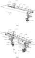
- FIG. 1 is a schematic structural diagram of an incubation device in an embodiment of the present invention.
- the incubation device is configured for an immunoassay test process.
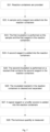
- Fig. 6 is a flowchart of a one-step method of an immunoassay test in an embodiment of the present invention.
- the one-step method mainly includes the following steps.
- reaction containers 130 are provided.
- the sample and the reagent in the reaction containers 130 are incubated. Incubation is generally a process of reacting the sample with the reagent in the reaction containers 130 in a stable temperature environment. Usually, after the reaction, the reaction containers 130 contain a magnetic particle complex formed by the sample and the reagent, and the reaction containers 130 also contain the unreacted sample and reagent. The incubation time is usually 3-60 minutes.
- the luminous quantity is measured.
- a signal reagent or a buffer solution is added into the reaction containers 130.
- Some immunoassay tests require incubation after the addition of the signal reagent. Signal incubation is usually performed in a stable temperature environment for 1-10 minutes. Signal incubation is able to enhance the luminous quantity or prepare for the generation of a light emitting signal.
- the first signal reagent is first added to prepare for signal generation, and then the luminous quantity is measured when the second signal reagent is added in S16.
- the buffer solution is added to recover the cleaned and separated magnetic particle complex, and the recovered magnetic particle complex is moved to a measuring device for measurement.
- the incubation unit 120 includes an incubation assembly 121 and an incubation driving assembly 122, the incubation assembly 121 being connected to the incubation driving assembly122 so as to drive the incubation assembly 121 to move linearly along a third direction 30.
- Incubation positions 1211 are provided on the incubation assembly 121, and the reaction containers 130 are placed in the incubation positions 1211.
- the transfer unit 110 includes a pick-and-place assembly 112 and a pick-and-place driving assembly 111, the pick-and-place driving assembly 111 being connected to the pick-and-place assembly 112, and the pick-and-place driving assembly 111 driving the pick-and-place assembly 112 to move along a first direction 10 and a second direction 20.
- the "and" in which the pick-and-place driving assembly 111 drives the pick-and-place assembly 112 to move along the first direction 10 and the second direction 20 is not a limit in time or order, that is, it does not mean that the two are "at the same time”, but means that the two are "both... and" functionally, that is, the pick-and-place driving assembly 111 drives the pick-and-place assembly112 to move along either the first direction or the second direction 20.
- the pick-and-place driving assembly 111 drive the pick-and-place assembly 112 to move along the first direction 10 first and then along the second direction 20, for example, when the pick-and-place assembly 112 moves one reaction container 130 into the incubation assembly 121; move along the second direction 20 and then along the first direction 10, for example, when the pick-and-place assembly 112 moves one reaction container 130 out of the incubation assembly 121; and move along the first direction 10 and the second direction 20 at the same time, for example, when the pick-and-place driving assembly 111 is reset.
- the application is in the first two cases, that is, the two are executed in sequence.
- the first direction 10, the second direction 20 and the third direction 30 include positive and negative directions, and during specific movement, the assembly able to move along the positive direction or the negative direction of the direction.
- the incubation driving assembly121 drives the incubation assembly 121 to move linearly along the third direction 30, and the incubation driving assembly 121 able to move linearly along the positive direction or the negative direction of the third direction 30.
- the first direction 10 and the third direction 30 are horizontal directions
- the second direction 20 is a vertical direction
- the first direction 10 and the second direction 20 are perpendicular.
- the first direction 10 is an X-axis direction
- the third direction 30 is a Y-axis direction
- the second direction 20 is a Z-axis direction.
- the incubation positions 1211 are arranged in a matrix on the incubation assembly 121 (That is, a multi-row and multi-column arrangement form).
- the incubation assembly 121 is of a cuboid-like block structure.
- a plurality of rows of incubation positions 1211 are arranged along the third direction 30, and a plurality of columns of incubation positions 1211 are arranged along the first direction 10. Further, the difference between the number of rows and the number of columns of the incubation positions 1211 does not exceed 5.
- the incubation assembly 121 and the pick-and-place assembly 112 are more reasonable in division of labor and cooperation, and the problems that the moving travel of one assembly in the movement direction is too long, the moving travel of the other assembly in the movement direction is too short, and the like are avoided, so that the transfer efficiency of the reaction containers 130 is improved on the whole.
- the sizes of the transfer unit 110, the incubation unit 120 and the whole machine are reduced, and the reaction efficiency per unit area is improved.
- the number of the incubation positions 1211 is not smaller than 150, and continuous testing of the incubation device of the application is guaranteed.
- the incubation positions 1211 are uniformly arranged on the incubation assembly 121, and fifteen rows and fifteen columns of incubation positions 1211 are arranged on the incubation assembly 121. Since the incubation positions 1211 are arranged in a matrix on the incubation assembly 121, the incubation positions 1211 are uniformly distributed on the incubation assembly 121.
- At least one access station is provided on the incubation device along the third direction 30 for the transfer unit 110 to move the reaction container 130 into the incubation assembly 121 and move the reaction container 130 out of the incubation assembly 121.
- the access station is an absolute position, configured to identify the absolute coordinate position at which the assembly works or performs a task, and does not move along with the movement of the incubation unit 120 and the transfer unit 110.
- the access station of the incubation device is located on a straight line where a moving trajectory of the pick-and-place assembly 112 along the first direction 10 is located.
- the incubation driving assembly 122 drives the incubation assembly 121 to move linearly along the third direction 30 so as to convey any row of incubation positions 1211 on the incubation assembly 121 to the access station
- the pick-and-place driving assembly 111 drives the pick-and-place assembly 112 to linearly move along the first direction 10 so as to drive the pick-and-place assembly 112 to above a certain row and any column of incubation positions 1211 located on the incubation assembly 121 of the access station, thereby traversing the incubation positions 1211 on the incubation assembly 121.
- the incubation assembly 121 is slidably connected to the incubation driving assembly 122. In this way, the driving load of the incubation driving assembly 122 is reduced to facilitate high speed movement of the incubation assembly 121.
- the incubation driving assembly 122 is located below the incubation assembly 121, which makes full use of the size in the vertical direction, further reduces the size of the incubation device along the horizontal direction, and facilitate reduction of the sizes of the incubation device and the automatic analysis device.
- the incubation driving assembly 122 is located below the incubation assembly 121, the incubation positions 1211 are uniformly distributed on the incubation assembly 121, and the problem that the incubation positions cannot be distributed on the incubation assembly due to the fact that a driving assembly is installed on the incubation assembly in the conventional art is solved.
- the pick-and-place driving assembly 111 drives the pick-and-place assembly 112 to only move along the first direction 10 and the second direction 20 but not along the third direction, so that the transfer structure is simplified, the driving load is reduced, and the reaction container 130 is transferred more efficiently.
- the number of incubation positions 1211 needs to be increased by increasing the size of the incubation disc, but increasing the size of the incubation disc leads to overlarge control load and large difficulty of the driving control technology on one hand, and on the other hand, the incubation positions 1211 of the incubation disc have high machining precision requirements and great machining challenges on the incubation disc.
- the size and precision requirements of an incubation pot wrapping the incubation disc are increased, a large-size pot body is difficult to machine in the existing manufacturing process, and the cost is very high even if the large-size pot body is manufactured.
- the transfer unit 110 only needs to move linearly along the first direction 10 to traverse all the incubation positions 1211 on the incubation assembly 121, and the incubation unit 120 and the transfer unit 110 able to move at a high speed in a coordinated manner, so that the efficiency of traversing all the incubation positions 1211 on the incubation assembly 121 and the reaction containers 130 thereon is improved, and the high-flux testing is realized.
- the incubation assembly 121 moves linearly along the third direction 30 so as to convey a row of incubation positions where an empty incubation position 1211 is located to the access position of the incubation device, the pick-and-place assembly 112 moves linearly along the first direction 10 to above the empty incubation position 1211, and the pick-and-place assembly 112 lifts along the second direction 20 to move the reaction container 130 filled with the sample and the reagent into the empty incubation position 1211.
- the incubation assembly 121 moves linearly along the third direction 30 so as to convey the reaction container 130 that needs to be cleaned and separated after incubation for a set time to the access position of the incubation device, the pick-and-place assembly 112 moves linearly along the first direction 10 to above the incubation position 1211 where the reaction container 130 is located, and the pick-and-place assembly 112 lifts along the second reaction 20 to move the reaction container 130 out.
- the incubation assembly 121 moves linearly along the third direction so as to convey the reaction container 130 that contains the signal reagent and needs to measure the luminous quantity to the access position of the incubation device
- the pick-and-place assembly 112 moves linearly along the first direction 10 to above the incubation position 1211 where the reaction container 130 is located, and the pick-and-place assembly 112 lifts along the second direction 20 to move he reaction container 130 out.
- the incubation assembly 121 moves linearly along the third direction so as to convey the cleaned and separated reaction container 130 that contains the signal reagent or the buffer solution and needs to measure the luminous quantity to the access position of the incubation device, and the transfer unit 110 moves the reaction container 130 out. From the above, for the reaction container 130 that contains the signal reagent or the buffer solution and does not need to be incubated, the incubation assembly 121 is configured to transfer the reaction container 130.
- a sample and a first reagent are added into the reaction container 130.
- different samples and first reagents are correspondingly selected according to different test items.
- some test items also need to uniformly mix the sample and the first reagent in the reaction container 130.
- the second incubation is performed on the reactant that contains the second reagent in the reaction container 130.
- the incubation assembly 121 moves linearly along the third direction 30 so as to convey the empty incubation position 1211 to the access position of the incubation device, and the transfer unit 110 moves the reaction container 130 filled with the sample and the first reagent into the incubation position 1211.
- the incubation assembly 121 moves linearly along the third direction 30 so as to convey the reaction container 130 that needs to be filled with the second reagent to the access position of the incubation device, and the transfer unit 110 moves the reaction container 130 out.
- the incubation assembly 121 moves linearly along the third direction 30 so as to convey the empty incubation position 1211 to the access position of the incubation device, and then the transfer unit 110 moves the reaction container 130 filled with the second reagent into the incubation position 1211.
- the incubation assembly 121 moves linearly along the third direction 30 so as to convey the reaction container 130 that needs to be cleaned and separated after the second incubation for a set time to the access position of the incubation device, and the transfer unit 110 moves the reaction container 130 out.
- the subsequent steps of the delayed one-step test and the role and function of the incubation device in the subsequent steps are the same as or similar to those of the one-step method and will not be elaborated herein.
- Fig. 8 is a flowchart of a two-step method of an immunoassay test in an embodiment of the present invention.
- the two-step method mainly includes the following steps that: the main difference between the two-step method and the aforementioned delayed one-step method is S34-S37 which are briefly introduced below, and the rest of the steps are the same as or similar to those of the one-step method and will not be elaborated herein.
- S34-S37 of the two-step method is as follows.
- a sample and a first reagent in the reaction container 130 are cleaned and separated for the first time.
- a second reagent is added into to the reaction container 130.
- different second reagents are correspondingly selected according to different test items.
- some test items also need to uniformly mix a reactant that contains the second reagent in the reaction container 130.
- the second incubation is performed on the reactant that contains the second reagent in the reaction container 130.
- the second cleaning and separation is performed on the incubated reactant in the reaction container 130.
- the incubation assembly 121 moves linearly along the third direction 30 so as to convey the empty incubation position 1211 to the access position of the incubation device, and the transfer unit 110 moves the reaction container 130 filled with the sample and the first reagent into the incubation position 1211.
- the incubation assembly 121 moves linearly along the third direction 30 so as to convey the reaction container 130 that needs the first cleaning and separation after the incubation for a set time to the access position of the incubation device, and the transfer unit 110 moves the reaction container 130 out.
- the reaction container 130 after the first cleaning and separation is directly transferred by the transfer unit 110 to be filled with the sample and the second reagent.
- the pick-and-place assembly 112 includes at least two grippers, the reaction container 130 that needs to be filled with the second reagent after the first cleaning and separation is buffered and transferred by the incubation assembly 121.
- the incubation assembly 121 When transferring by the incubation assembly 121, the moving travel of each gripper along the first direction 10 is reduced, and the space setting and working time of each gripper is more flexible.
- the incubation assembly 121 moves linearly along the third direction 30 so as to convey the empty incubation position 1211 to the access position of the incubation device, and then one gripper of the transfer unit 110 moves the cleaned reaction container 130 into the incubation position 1211.
- the incubation assembly 121 moves linearly along the third direction of 30 so as to convey the reaction container 130 that needs to be filled with the second reagent on the incubation position 1211 to the access position of the incubation device, and another gripper of the transfer unit 110 moves the reaction container 130 out.
- the incubation assembly 121 moves linearly along the third direction 30 so as to convey the empty incubation position 1211 to the access position of the incubation device, and then the transfer unit 110 moves the reaction container 130 filled with the second reagent into the incubation position 1211. After the second incubation is performed on the reactant in the reaction container 13 for a set time, the incubation assembly 121 moves linearly along the third direction 30 so as to convey the reaction container 130 that needs the second cleaning and separation after incubation for a set time to the access position of the incubation device, and the transfer unit 110 moves the reaction container 130 out.
- the subsequent steps of the two-step test and the role and function of the incubation device in the subsequent steps are the same or similar to those of the delayed one-step method and will not be elaborated herein.
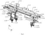
- Figs. 2, 3 , and 4 are schematic structural diagrams of the pick-and-place assembly 112 in three embodiments of the application respectively.
- the pick-and-place assembly 112 includes a first gripper 112A, the pick-and-place driving assembly 111 being connected to the first gripper 112A, and the pick-and-place driving assembly 111 driving the first gripper 112A to move along the first direction 10 and the second direction 20.
- the pick-and-place driving assembly 111 includes a fixed plate 111G, a first guide rail 111C, a first driving piece 111A, a first transmission assembly 111E, a first switching assembly 111H1, a first lifting guide rail 111C1, a first lifting driving assembly 111A1, and a first lifting transmission assembly 111E1.
- the first guide rail 111C is fixedly connected to the fixed plate 111G, the first guide rail 111C extends along the first direction 10, and the first switching assembly 111H1 is slidably connected to the first guide rail 111C.
- the first driving piece 111A is fixedly connected to the fixed plate 111G, and the first driving piece 111A is a motor.
- the first driving assembly 111E is connected to the output end of the first driving assembly 111A and the first switching assembly 111H1 respectively, so that the first driving assembly 111A drives the first switching assembly 111H1 to slide along the first guide rail 111C.
- the first lifting guide rail 111C1 is fixedly connected to the first switching assembly 111H1, the first lifting guide rail 111C1 extends along the second direction 20, and the first gripper 112A is slidably connected to the first lifting guide rail 111C1.
- the first lifting driving piece 111A1 is fixedly connected to the first switching assembly 111H1, and the first lifting driving piece 111A1 is a motor.
- the first lifting transmission assembly 111E1 is arranged on the first switching assembly 111H 1.
- the first lifting driving assembly 111E1 is connected to the output end of the first lifting driving piece 111A1 and the first gripper 112A.
- the pick-and-place assembly 112 includes a first gripper 112A and a second gripper 112B.
- the pick-and-place driving assembly 111 includes a fixed plate 111G, a first guide rail 111C, a first driving piece 111A, a second driving piece 111B, a first transmission assembly 111E, a second transmission assembly 111J, a first switching assembly 111H1, a second switching assembly 111H2, a first lifting guide rail 111C1, a second lifting guide rail 111C2, a first lifting driving piece 111A1, a second lifting driving piece 111A2, a first lifting transmission assembly 111E1, and a second lifting transmission assembly 111E2.
- the first switching assembly 111H1 is slidably connected to the first guide rail 111C, and the second switching assembly 111H2 is also slidably connected to the first guide rail 111C.
- the first transmission assembly 111E is arranged on the fixed plate 111G, and the first transmission assembly 111E is connected to the output end of the first driving piece 111A and the first switching assembly 111H1 respectively, so that the first driving piece 111A drives the first switching assembly 111H1 to slide along the first guide rail 111C.
- the second transmission assembly 111J and the second driving piece 111B are both arranged on the fixed plate 111G, and the second transmission assembly 111J is connected to the output end of the second driving piece 111B and the second switching assembly 111H2 respectively, so that the second driving piece 111B drives the second switching assembly 111H2 to slide along the first guide rail 111C.
- the second lifting guide rail 111C2 is fixedly connected to the second switching assembly 111H2, the second lifting guide rail 111C2 extends along the second direction 20, and the second gripper 112C is slidably connected to the second lifting guide rail 111C2.
- the second lifting driving piece 111A2 is fixedly connected to the second switching assembly 111H2, and the second lifting driving piece 111A2 is a motor.
- the second lifting transmission assembly 111E2 is arranged on the second switching assembly 111H2.
- the second lifting transmission assembly 111E2 is connected to the output end of the second lifting driving piece 111A2 and the second gripper 112B respectively.
- the first switching assembly 111H1 and the second switching assembly 111H2 both slide along the first guide rail 111C with at least one section of overlapped trajectory, so that both first gripper 112A and second gripper 112B able to move to above the incubation assembly 121. Further, there is at least one section of overlapped motion trajectory of the first gripper 112A and the second gripper 112B between the head and tail columns of the incubation positions of the incubation assembly 121. Specifically, as shown in Fig. 1 , the incubation assembly 121 moves along the third direction 30.
- Incubation positions 1211 arranged in a matrix are provided on the incubation assembly 121, that is, the plurality of incubation positions 1211 are arranged along the first direction 10 (called a column), and the plurality of incubation positions 1211 are arranged along the third direction 30 (called a row).
- the incubation assembly 121 moves linearly along the third direction 30, and when the first gripper 112A moves along the first direction 10, same able to move to above all the incubation positions 1211 arranged along the first direction 10 on the incubation assembly 121.
- the incubation assembly 121 moves linearly along the third direction 30, and when the second gripper 112B moves along the first direction 10, same able to move to above all the incubation positions 1211 arranged along the first direction 10 on the incubation assembly 121.
- the straight lines where the trajectories of the first gripper 112A and the second gripper 112B are located coincide. Since the number of access stations of the incubation device is equal to the number of non-coincident motion trajectories of the pick-and-place assembly 112 along the first direction 10, the number of access stations of the incubation device in the embodiment is one. That is, in the embodiment, the incubation device is provided with one access station.
- the incubation device is provided with only one access station, and the incubation assembly 121 does not need to move to a plurality of access stations when moving along the third direction 30, which further reduces the moving travel of the incubation assembly 121, improves the efficiency of the incubation assembly 121 in treating the reaction container 130, saves the operation space of the incubation assembly 121, and reduces the size of the whole machine.
- the second gripper 112B moves the reactor that needs to be filled with the second reagent out of the incubation assembly 121, moves the reaction container that needs to be incubated after being filled with the reagent into the incubation assembly 121, and moves the reactor that needs to be measured after being moved and buffered by the incubation assembly 121 out of the incubation assembly 121.
- the first gripper 112A moves the reaction container 130 in and out and the second gripper 112B moves the reaction container 130 in and out at different times, that is, only one gripper moves the reaction container 130 in and out each time the corresponding incubation assembly 121 moves linearly along the third direction 30 to the access position.
- the pick-and-place assembly 112 includes a first gripper 112A, a second gripper 112B, and a third gripper 112C.
- the pick-and-place driving assembly 111 includes a fixed plate 111G, a first guide rail 111C, a second guide rail 111D, a first driving piece 111A, a second driving piece 111B, a third driving piece 111I, a first transmission assembly 111E, a second transmission assembly 111J, a third transmission assembly 111F, a first switching assembly 111H1, a second switching assembly 111H2, a third switching assembly 111H3, a first lifting guide rail 111C1, a second lifting guide rail 111C2, a third lifting guide rail 111C3, a first lifting driving piece 111A1, a second lifting driving piece 111A2, a third lifting driving piece 111A3, a first lifting transmission assembly 111E1, a second lifting transmission assembly 111E2, and a third lifting transmission transmission
- first guide rail 111C is parallel to the second guide rail 111D.
- the first switching assembly 111H1 is slidably connected to the first guide rail 111C
- the second switching assembly 111H2 is also slidably connected to the first guide rail 111C
- the third switching assembly 111H3 is slidably connected to the second guide rail 111D.
- the first transmission assembly 111E is arranged on the fixed plate 111G, and the first transmission assembly 111E is connected to the output end of the first driving piece 111A and the first switching assembly 111H1 respectively, so that the first driving piece 111A drives the first switching assembly 111H1 to slide along the first guide rail 111C.
- the second transmission assembly 111J and the second driving piece 111B are both arranged on the fixed plate 111G, and the second transmission assembly 111J is connected to the output end of the second driving piece 111B and the second switching assembly 111H2 respectively, so that the second driving piece 111B drives the second switching assembly 111H2 to slide along the first guide rail 111C.
- the third transmission assembly 111F and the third driving piece 111I are both arranged on the fixed plate 111G, and the third transmission assembly 111F is connected to the output end of the third driving piece 111I and the third switching assembly 111H3 respectively, so that the third driving piece 111I drives the third switching assembly 111H3 to slide along the first guide rail 111C.
- the first lifting guide rail 111C1 is fixedly connected to the first switching assembly 111H1, the first lifting guide rail 111C1 extends along the second direction 20, and the first gripper 112A is slidably connected to the first lifting guide rail 111C1.
- the first lifting driving piece 111A1 is fixedly connected to the first switching assembly 111H1, and the first lifting driving piece 111A1 is a motor.
- the first lifting transmission assembly 111E1 is arranged on the first switching assembly 111H1.
- the first lifting driving assembly 111E1 is connected to the output end of the first lifting driving piece 111A1 and the first gripper 112A respectively.
- the first gripper 112A and the second gripper 112B move the reaction container 130 into and out of the incubation assembly 121 at the first access station, and the third gripper 112C moves the reaction container 130 into or out of the incubation assembly 121 at the second access station.
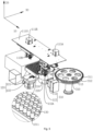
- the automatic analysis device further includes a cleaning and separation unit 310.
- the cleaning and separation unit 310 is non-nested with the incubation unit 120, that is, the cleaning and separation unit 310 and the incubation unit 120 are independently arranged, and the cleaning and separation unit 310 is configured to remove the unbound sample and reagent in the reaction container 130.
- the cleaning and separation unit 310 is configured to clean and separate the reaction container 130 entering the cleaning and separation unit 310 and remove the unbound sample and reagent in the reaction container 130.
- the moving-in station is located upstream of the moving-out station along the rotation direction of the rotary cleaning plate 311. Specifically, along the direction of rotating forward of the cleaning plate 311, the moving-out station is in the front, and the moving-out station is followed by the moving-out station.
- the cleaning plate 311 rotates forward to one cleaning and separation position 313 so as to position the reaction container 130 on the target cleaning and separation position 313 to the moving-out station.
- the pick-and-place assembly 112 moves along the first direction 10 to above the moving-out station so as to move the reaction container 130 on the target cleaning and separation position 313 out at the moving-out station.
- the measuring assembly further includes optical structures such as optical signal collection and calibration.
- the assembly of the measuring unit 210 is connected or installed to the pot body assembly in a general manner, such as directly installed and fixed to the pot body assembly or installed to the pot body assembly through optical fiber connection.
- the position where the measuring assembly is installed on the measuring unit 210 is a signal reading position, and the reaction container that contains the signal reagent completes the reading of the optical signal at the measuring position.
- the measuring unit 210 further includes a temperature control assembly.
- the temperature control assembly includes an insulation material, a heater, a temperature sensor, etc., to provide a stable temperature environment for the measuring unit 210.
- the cleaning and separation unit 310 and the measuring unit 210 are located on the same side of the incubation unit 120. In this way, the space on one side of the incubation unit 120 is fully utilized, which makes the structure of the automatic analysis unit more compact.
- the rotating center of the rotary cleaning plate 311 of the cleaning and separation unit 310 and the rotating center of the rotary measuring plate 220 of the measuring unit 210 are located on both sides of the motion trajectory of the pick-and-place assembly of the transfer unit 110 along the first direction 10 respectively.
- the rotating center of the rotary cleaning plate 311 of the cleaning and separation unit 310 and the rotating center of the rotary measuring plate 220 of the measuring unit 210 are located on both sides of the motion trajectory of the first gripper 112A of the transfer unit 110 along the first direction 10 respectively.
- the moving travel of the transfer unit 110 along the first direction 10 is shorter, and on the other hand, the space on both sides of the first direction 10 is fully utilized, so that the automatic analysis device has a more compact structure and a higher space utilization.
- the pick-and-place assembly 112 includes the first gripper 112A and the second gripper 112B as an example.
- the incubation assembly 121 moves linearly along the third direction 30 to the access station of the incubation device so as to convey the empty incubation position 1211 to the access position of the incubation device.
- the second gripper 112B moves along the first direction 10 to above the incubation assembly 121 (specifically, above the access position of the incubation device, the same below, will not be elaborated), and lifts along the second direction 20 so as to move the reaction container 130 that contains the sample and the first reagent into the incubation position 1211 of the incubation unit 120.
- the first incubation is performed on the sample and the first reagent in the reaction container 130 for a set time on the incubation assembly 121.
- the reaction container 130 contains a magnetic particle complex formed by the binding of the sample and the first reagent.
- the incubation time is usually 3-60 minutes.
- the incubation assembly 121 moves linearly along the third direction 30 to the access station of the incubation device so as to convey the reaction container 130 that needs the first cleaning and separation after the first incubation for a set time to the access station of the incubation device.
- the first gripper 112A moves along the first direction 10 to above the incubation assembly 121, and lifts along the second direction 20 so as to move the reaction container 130 out.
- the first gripper 112A moves along the first direction 10 to above the moving-in station on the cleaning and separation unit 310, the cleaning plate 311 rotates forward one cleaning and separation position 313 so as to position the empty cleaning and separation position 313 to the moving-in station.
- the first gripper 112A lifts along the second direction 20 to move the reaction container 130 into the cleaning and separation position 313.
- the cleaning plate 311 rotates to drive the reaction container 130 forward in the cleaning and separation unit 310, and the first cleaning and separation is performed on the reaction container 130 to remove the unbound sample and reagent in the reaction container 130.
- the cleaning plate 311 rotates to position the reaction container 130 after the first cleaning and separation to the moving-out station on the cleaning and separation unit 310.
- the first gripper 112A moves along the first direction 10 to above the moving-out station on the cleaning and separation unit 310, and moves the reaction container 130 out along the second direction 20.
- the incubation assembly 121 moves linearly along the third direction 30 to the access position of the incubation device so as to convey the empty incubation position 1211 to the access position of the incubation device.
- the first gripper 112A moves along the first direction 10 to above the incubation assembly 121, and lifts along the second direction 20 to move the reaction container 130 after the first cleaning and separation into the incubation position 1211 of the incubation unit 120.
- the reaction container 130 after the first cleaning and separation is buffered on the incubation position 1211 of the incubation unit 120.
- the incubation assembly 121 moves linearly along the third direction 30 to the access position of the incubation device so as to convey the empty incubation position 1211 to the access position of the incubation device.
- the second gripper 112B moves along the first direction 10 to above the incubation assembly 121, and lifts along the second direction 20 to move the reaction container 130 added with the second reagent into the incubation position 1211 of the incubation unit 120.
- the second incubation is performed on the magnetic particle complex after first cleaning and separation of the reaction container 130 and the second reagent in the reaction container 130 for the set time on the incubation assembly 121.
- the new magnetic particle complex is formed by binding in the reaction container 130 after the second reaction.
- the incubation time is usually 3-60 minutes.
- the incubation assembly 121 moves linearly along the third direction 30 to the access position of the incubation device so as to convey the reaction container 130 that needs the second cleaning and separation after the second incubation for a set time to the access position of the incubation device.
- the first gripper 112A moves along the first direction 10 to above the incubation assembly 121, and lifts along the second direction 20 so as to move the reaction container 130 out.
- the first gripper 112A moves along the first direction 10 to above the moving-in station on the cleaning and separation unit 310, and the cleaning plate 311 rotates forward one cleaning and separation position 313 so as to position the empty cleaning and separation position 313 to the moving-in station.
- the first gripper 112A lifts along the second direction 20 to move the reaction container 130 into the cleaning and separation position 313.
- the incubation assembly 121 moves linearly along the third direction 30 to the access position of the incubation device so as to convey the empty incubation position 1211 to the access position of the incubation device.
- the first gripper 112A moves along the first direction 10 to above the incubation assembly 121, and lifts along the second direction 20 to move the reaction container 130 filled with the signal reagent after the second cleaning and separation into the incubation position 1211 of the incubation unit 120.
- the reaction container 130 filled with the signal reagent after the second cleaning and separation is buffered on the incubation position 1211 of the incubation unit 120. If the reaction container 130 requires signal incubation, signal incubation is performed on the incubation position 1211 of the incubation unit 120 for a set time.
- the incubation assembly 121 moves linearly along the third direction 30 to the access position of the incubation device so as to convey the reaction container that needs to be measured after the second cleaning and separation to the access position of the incubation device.
- the second gripper 112B moves along the first direction 10 to above the incubation assembly 121, and lifts along the second direction 20 to move the reaction container 130 out of the incubation position 1211 of the incubation unit 120.
- the second gripper 112B moves along the first direction 10 to above the access position of the measuring unit 210, and lifts along the second direction 20 to move the reaction container 130 into the measuring positions on the measuring plate 220.
- the measuring plate 220 rotates to position the reaction container 130 to a signal reading position, and the measuring assembly reads the optical signal in the reaction container 130.
- the transfer unit 110 of the present invention is configured to move the reaction container 130 into and out of the incubation unit 120, and the incubation unit 120 is configured to incubate the reaction container 130 that contains the reactant or the buffered, cleaned and separated reaction container 130.
- the incubation assembly 121 moves linearly along the third direction 30 so as to convey the target incubation position 1211 to the access position of the incubation device.
- the pick-and-place driving assembly 111 drives the pick-and-place assembly 112 to move along the first direction 10 and the second direction 20 so as to move the reaction container 130 into or out of the incubation position 1211 at the access position of the incubation device.
- the rotating center of the rotary cleaning plate 311 of the cleaning and separation unit 310 and the rotating center of the rotary measuring plate 220 of the measuring unit 210 are located on both sides of the motion trajectory of the first gripper 112A of the transfer unit 110 along the first direction 10 respectively.
- the automatic analysis device of the application is compact in structure, low in manufacturing cost, and efficiently achieve high-flux continuous testing.
- the first feature "on” or “under” the second feature may be direct contact of the first and second features, or the first and second features may be in indirect contact through an intermediate medium.
- the first feature "over”, “above” and “on” the second feature may mean that the first feature is directly above or obliquely above the second feature, or it only means that the level of the first feature is higher than the second feature.
- the first feature “neath”, “below” and “under” the second feature may mean that the first feature is directly below or obliquely below the second feature, or it only means that the level of the first feature is smaller than the second feature.
Landscapes
- Health & Medical Sciences (AREA)
- Life Sciences & Earth Sciences (AREA)
- Immunology (AREA)
- Engineering & Computer Science (AREA)
- Chemical & Material Sciences (AREA)
- Pathology (AREA)
- Analytical Chemistry (AREA)
- Biochemistry (AREA)
- General Health & Medical Sciences (AREA)
- General Physics & Mathematics (AREA)
- Physics & Mathematics (AREA)
- Molecular Biology (AREA)
- Biomedical Technology (AREA)
- Hematology (AREA)
- Urology & Nephrology (AREA)
- Biotechnology (AREA)
- Cell Biology (AREA)
- Microbiology (AREA)
- Food Science & Technology (AREA)
- Medicinal Chemistry (AREA)
- Robotics (AREA)
- Inorganic Chemistry (AREA)
- Automatic Analysis And Handling Materials Therefor (AREA)
Applications Claiming Priority (1)
| Application Number | Priority Date | Filing Date | Title |
|---|---|---|---|
| PCT/CN2020/087568 WO2021217443A1 (zh) | 2020-04-28 | 2020-04-28 | 孵育装置和自动分析装置 |
Publications (2)
| Publication Number | Publication Date |
|---|---|
| EP4145136A1 true EP4145136A1 (de) | 2023-03-08 |
| EP4145136A4 EP4145136A4 (de) | 2023-07-05 |
Family
ID=78331576
Family Applications (1)
| Application Number | Title | Priority Date | Filing Date |
|---|---|---|---|
| EP20934135.3A Pending EP4145136A4 (de) | 2020-04-28 | 2020-04-28 | Inkubationsvorrichtung und automatische analysevorrichtung |
Country Status (3)
| Country | Link |
|---|---|
| US (1) | US20230236180A1 (de) |
| EP (1) | EP4145136A4 (de) |
| WO (1) | WO2021217443A1 (de) |
Family Cites Families (6)
| Publication number | Priority date | Publication date | Assignee | Title |
|---|---|---|---|---|
| EP2413136B1 (de) * | 2003-07-18 | 2013-07-03 | Bio-Rad Laboratories, Inc. | System und Verfahren zur Erkennung mehrerer Analyten |
| ES2614190T3 (es) * | 2014-09-17 | 2017-05-30 | Siemens Healthcare Diagnostics Products Gmbh | Dispositivo de incubación para un aparato de análisis automático |
| CN206339561U (zh) * | 2016-07-05 | 2017-07-18 | 深圳普门科技有限公司 | 小型电化学发光免疫分析仪 |
| CN106841644B (zh) * | 2017-01-06 | 2019-05-31 | 深圳迎凯生物科技有限公司 | 自动分析装置及样本分析方法 |
| CN111373265B (zh) * | 2018-03-26 | 2024-08-16 | 深圳迈瑞生物医疗电子股份有限公司 | 化学发光分析仪及其分析方法 |
| CN109406804B (zh) * | 2018-10-30 | 2022-01-25 | 深圳泰乐德医疗有限公司 | 全自动化学发光测定仪 |
-
2020
- 2020-04-28 US US17/921,994 patent/US20230236180A1/en active Pending
- 2020-04-28 EP EP20934135.3A patent/EP4145136A4/de active Pending
- 2020-04-28 WO PCT/CN2020/087568 patent/WO2021217443A1/zh not_active Ceased
Also Published As
| Publication number | Publication date |
|---|---|
| US20230236180A1 (en) | 2023-07-27 |
| EP4145136A4 (de) | 2023-07-05 |
| WO2021217443A1 (zh) | 2021-11-04 |
Similar Documents
| Publication | Publication Date | Title |
|---|---|---|
| CN207866714U (zh) | 化学发光检测仪 | |
| CN106645765B (zh) | 自动分析装置及样本分析方法 | |
| CN110007099B (zh) | 自动分析装置及样本分析方法 | |
| US11162962B2 (en) | Automatic analysis device and sample analysis method | |
| CN113219193B (zh) | 样本分析方法和样本分析装置 | |
| CN113567691B (zh) | 孵育装置和自动分析装置 | |
| CN114200123B (zh) | 化学发光免疫分析仪 | |
| CN116840499A (zh) | 自动分析装置及其样本分析方法 | |
| CN116047096A (zh) | 样本自动分析装置 | |
| US20170059562A1 (en) | Immune measuring apparatus and immune measuring method | |
| EP4624934A1 (de) | Automatische probenanalysevorrichtung | |
| CN216771753U (zh) | 化学发光免疫分析仪 | |
| EP4083631A1 (de) | Verdünnungsverfahren und verdünnungsvorrichtung | |
| CN115684618A (zh) | 自动分析装置及自动分析方法 | |
| CN113219191B (zh) | 分析装置 | |
| CN113219195B (zh) | 分析装置 | |
| EP4145136A1 (de) | Inkubationsvorrichtung und automatische analysevorrichtung | |
| CN211697837U (zh) | 分析装置 | |
| CN113219194B (zh) | 分析装置 | |
| WO2025190407A1 (zh) | 样本分析装置 | |
| CN101793900A (zh) | 化学发光免疫分析用反应杯自动连续加载装置 | |
| CN218727363U (zh) | 自动分析装置 | |
| CN113219192B (zh) | 反应器转移方法 | |
| CN218675016U (zh) | 自动分析装置 | |
| CN218546775U (zh) | 自动分析装置 |
Legal Events
| Date | Code | Title | Description |
|---|---|---|---|
| STAA | Information on the status of an ep patent application or granted ep patent |
Free format text: STATUS: THE INTERNATIONAL PUBLICATION HAS BEEN MADE |
|
| PUAI | Public reference made under article 153(3) epc to a published international application that has entered the european phase |
Free format text: ORIGINAL CODE: 0009012 |
|
| STAA | Information on the status of an ep patent application or granted ep patent |
Free format text: STATUS: REQUEST FOR EXAMINATION WAS MADE |
|
| 17P | Request for examination filed |
Effective date: 20221118 |
|
| AK | Designated contracting states |
Kind code of ref document: A1 Designated state(s): AL AT BE BG CH CY CZ DE DK EE ES FI FR GB GR HR HU IE IS IT LI LT LU LV MC MK MT NL NO PL PT RO RS SE SI SK SM TR |
|
| A4 | Supplementary search report drawn up and despatched |
Effective date: 20230606 |
|
| RIC1 | Information provided on ipc code assigned before grant |
Ipc: G01N 33/53 20060101ALI20230601BHEP Ipc: G01N 35/04 20060101AFI20230601BHEP |
|
| DAV | Request for validation of the european patent (deleted) | ||
| DAX | Request for extension of the european patent (deleted) | ||
| STAA | Information on the status of an ep patent application or granted ep patent |
Free format text: STATUS: EXAMINATION IS IN PROGRESS |
|
| 17Q | First examination report despatched |
Effective date: 20250317 |