EP4145428A1 - Elektronische vorrichtung - Google Patents
Elektronische vorrichtung Download PDFInfo
- Publication number
- EP4145428A1 EP4145428A1 EP21803031.0A EP21803031A EP4145428A1 EP 4145428 A1 EP4145428 A1 EP 4145428A1 EP 21803031 A EP21803031 A EP 21803031A EP 4145428 A1 EP4145428 A1 EP 4145428A1
- Authority
- EP
- European Patent Office
- Prior art keywords
- magnetic
- housing
- electronic device
- bracket
- elements
- Prior art date
- Legal status (The legal status is an assumption and is not a legal conclusion. Google has not performed a legal analysis and makes no representation as to the accuracy of the status listed.)
- Withdrawn
Links
Images



Classifications
-
- G—PHYSICS
- G06—COMPUTING OR CALCULATING; COUNTING
- G06F—ELECTRIC DIGITAL DATA PROCESSING
- G06F1/00—Details not covered by groups G06F3/00 - G06F13/00 and G06F21/00
- G06F1/16—Constructional details or arrangements
- G06F1/1613—Constructional details or arrangements for portable computers
- G06F1/1633—Constructional details or arrangements of portable computers not specific to the type of enclosures covered by groups G06F1/1615 - G06F1/1626
- G06F1/1637—Details related to the display arrangement, including those related to the mounting of the display in the housing
- G06F1/1641—Details related to the display arrangement, including those related to the mounting of the display in the housing the display being formed by a plurality of foldable display components
-
- H—ELECTRICITY
- H05—ELECTRIC TECHNIQUES NOT OTHERWISE PROVIDED FOR
- H05K—PRINTED CIRCUITS; CASINGS OR CONSTRUCTIONAL DETAILS OF ELECTRIC APPARATUS; MANUFACTURE OF ASSEMBLAGES OF ELECTRICAL COMPONENTS
- H05K5/00—Casings, cabinets or drawers for electric apparatus
- H05K5/02—Details
- H05K5/0217—Mechanical details of casings
- H05K5/0226—Hinges
-
- G—PHYSICS
- G06—COMPUTING OR CALCULATING; COUNTING
- G06F—ELECTRIC DIGITAL DATA PROCESSING
- G06F1/00—Details not covered by groups G06F3/00 - G06F13/00 and G06F21/00
- G06F1/16—Constructional details or arrangements
- G06F1/1613—Constructional details or arrangements for portable computers
- G06F1/1633—Constructional details or arrangements of portable computers not specific to the type of enclosures covered by groups G06F1/1615 - G06F1/1626
- G06F1/1637—Details related to the display arrangement, including those related to the mounting of the display in the housing
- G06F1/1652—Details related to the display arrangement, including those related to the mounting of the display in the housing the display being flexible, e.g. mimicking a sheet of paper, or rollable
-
- G—PHYSICS
- G06—COMPUTING OR CALCULATING; COUNTING
- G06F—ELECTRIC DIGITAL DATA PROCESSING
- G06F1/00—Details not covered by groups G06F3/00 - G06F13/00 and G06F21/00
- G06F1/16—Constructional details or arrangements
- G06F1/1613—Constructional details or arrangements for portable computers
- G06F1/1633—Constructional details or arrangements of portable computers not specific to the type of enclosures covered by groups G06F1/1615 - G06F1/1626
- G06F1/1675—Miscellaneous details related to the relative movement between the different enclosures or enclosure parts
- G06F1/1677—Miscellaneous details related to the relative movement between the different enclosures or enclosure parts for detecting open or closed state or particular intermediate positions assumed by movable parts of the enclosure, e.g. detection of display lid position with respect to main body in a laptop, detection of opening of the cover of battery compartment
-
- G—PHYSICS
- G06—COMPUTING OR CALCULATING; COUNTING
- G06F—ELECTRIC DIGITAL DATA PROCESSING
- G06F1/00—Details not covered by groups G06F3/00 - G06F13/00 and G06F21/00
- G06F1/16—Constructional details or arrangements
- G06F1/1613—Constructional details or arrangements for portable computers
- G06F1/1633—Constructional details or arrangements of portable computers not specific to the type of enclosures covered by groups G06F1/1615 - G06F1/1626
- G06F1/1675—Miscellaneous details related to the relative movement between the different enclosures or enclosure parts
- G06F1/1679—Miscellaneous details related to the relative movement between the different enclosures or enclosure parts for locking or maintaining the movable parts of the enclosure in a fixed position, e.g. latching mechanism at the edge of the display in a laptop or for the screen protective cover of a PDA
-
- H—ELECTRICITY
- H01—ELECTRIC ELEMENTS
- H01F—MAGNETS; INDUCTANCES; TRANSFORMERS; SELECTION OF MATERIALS FOR THEIR MAGNETIC PROPERTIES
- H01F7/00—Magnets
- H01F7/02—Permanent magnets [PM]
-
- H—ELECTRICITY
- H04—ELECTRIC COMMUNICATION TECHNIQUE
- H04M—TELEPHONIC COMMUNICATION
- H04M1/00—Substation equipment, e.g. for use by subscribers
- H04M1/02—Constructional features of telephone sets
- H04M1/0202—Portable telephone sets, e.g. cordless phones, mobile phones or bar type handsets
- H04M1/0206—Portable telephones comprising a plurality of mechanically joined movable body parts, e.g. hinged housings
- H04M1/0208—Portable telephones comprising a plurality of mechanically joined movable body parts, e.g. hinged housings characterized by the relative motions of the body parts
- H04M1/0214—Foldable telephones, i.e. with body parts pivoting to an open position around an axis parallel to the plane they define in closed position
-
- H—ELECTRICITY
- H05—ELECTRIC TECHNIQUES NOT OTHERWISE PROVIDED FOR
- H05K—PRINTED CIRCUITS; CASINGS OR CONSTRUCTIONAL DETAILS OF ELECTRIC APPARATUS; MANUFACTURE OF ASSEMBLAGES OF ELECTRICAL COMPONENTS
- H05K5/00—Casings, cabinets or drawers for electric apparatus
- H05K5/02—Details
- H05K5/0217—Mechanical details of casings
-
- G—PHYSICS
- G09—EDUCATION; CRYPTOGRAPHY; DISPLAY; ADVERTISING; SEALS
- G09F—DISPLAYING; ADVERTISING; SIGNS; LABELS OR NAME-PLATES; SEALS
- G09F9/00—Indicating arrangements for variable information in which the information is built-up on a support by selection or combination of individual elements
- G09F9/30—Indicating arrangements for variable information in which the information is built-up on a support by selection or combination of individual elements in which the desired character or characters are formed by combining individual elements
- G09F9/301—Indicating arrangements for variable information in which the information is built-up on a support by selection or combination of individual elements in which the desired character or characters are formed by combining individual elements flexible foldable or roll-able electronic displays, e.g. thin LCD, OLED
-
- H—ELECTRICITY
- H04—ELECTRIC COMMUNICATION TECHNIQUE
- H04M—TELEPHONIC COMMUNICATION
- H04M1/00—Substation equipment, e.g. for use by subscribers
- H04M1/02—Constructional features of telephone sets
- H04M1/0202—Portable telephone sets, e.g. cordless phones, mobile phones or bar type handsets
- H04M1/026—Details of the structure or mounting of specific components
- H04M1/0266—Details of the structure or mounting of specific components for a display module assembly
- H04M1/0268—Details of the structure or mounting of specific components for a display module assembly including a flexible display panel
Definitions
- the present disclosure relates to the field of electronic technologies, and more particular, to an electronic device.
- Foldable devices are widely favored by users because they can not only meet needs of the users for large-size screens, but also avoid inconvenience of carrying caused by large-sized screens.
- the foldable devices usually require the users to manually unfold or fold.
- An embodiment of the present disclosure provides an electronic device, which can realize automatic unfolding or folding of a foldable electronic device.
- the embodiment of the disclosure provides an electronic device, including:
- An embodiment of the present disclosure provides an electronic device, including:
- the driving mechanism can be used to control the second magnetic mechanism to move to have the first magnetic mechanism and the second magnetic mechanism mutually attracted together or mutually repelled to be separated from each other, which can make the first housing and the second housing rotate relatively to each other to realize the automatic unfolding or folding of the foldable electronic device.
- the first magnetic mechanism includes: at least two first magnetic elements arranged side by side, and magnetic poles of adjacent two of the at least two first magnetic elements are unlike magnetic poles;
- the second magnetic mechanism includes: at least two second magnetic elements arranged side by side, and magnetic poles of adjacent two of the at least two second magnetic elements are unlike magnetic poles;
- the driving mechanism is configured to drive the at least two second magnetic elements to move between a first position and a second position to make the at least two second magnetic elements each correspond to different ones of the at least two first magnetic elements, and thereby magnetic poles of at least some of the at least two second magnetic elements and the first magnetic elements corresponding thereto are unlike magnetic poles when the at least two second magnetic elements are located at the first position, and magnetic poles of at least some of the at least two second magnetic elements and the first magnetic elements corresponding thereto are like magnetic poles when the at least two second magnetic elements are located at the second position.
- a number of the first magnetic elements in the first magnetic mechanism is one more than a number of the second magnetic elements in the second magnetic mechanism.
- adjacent two of the at least two second magnetic elements are abutted against each other; or adjacent two of the at least two second magnetic elements are spaced apart from each other.
- adjacent two of the at least two first magnetic elements are abutted against each other; or adjacent two of the at least two first magnetic elements are spaced apart from each other.
- a thickness of one of the first magnetic elements is the same as a thickness of one of the second magnetic elements.
- the first magnetic mechanism includes: at least two first magnetic elements arranged side by side, and magnetic poles of adjacent two of the at least two first magnetic elements are unlike magnetic poles;
- the second magnetic mechanism includes: one second magnetic element;
- the driving mechanism is configured to drive the second magnetic element to move between a first position and a second position to make the second magnetic element correspond to different ones of the at least two first magnetic elements and thereby a magnetic pole of the second magnetic element and a magnetic pole of the first magnetic element corresponding thereto are unlike magnetic poles when the second magnetic element is located at the first position, and a magnetic pole of the second magnetic element and a magnetic pole of the first magnetic element corresponding thereto are like magnetic poles when the second magnetic element is located at the second position.
- magnetic intensities of the first magnetic elements arranged at different positions are different in the at least two first magnetic elements arranged side by side.
- the driving mechanism includes a bracket and a driving element connected to the bracket, the second magnetic mechanism is disposed on the bracket, and the driving element is configured to drive the bracket to move and thereby to make the second magnetic mechanism move following the bracket.
- the second housing is provided with a limit groove
- the bracket is provided with a limit block
- the limit block is disposed in the limit groove
- the limit groove is configured to cooperate with the limit block to limit a movement track of the bracket.
- the driving mechanism further includes an elastic element, an end of the elastic element is connected to the bracket, another end of the elastic element abuts against the second housing, and the elastic element is configured to generate elastic deformation and thereby to switch between a compressed state and an extended state; the elastic element is deformed to be in the compressed state and the bracket is moved to a preset position when the driving element drives the bracket to move; and the elastic element is switched from the compressed state to the extended state and the bracket moves to an initial position when the driving element does not drive the bracket to move.
- the bracket is connected to the elastic element through a first connection element, and the first connection element is configured to limit a deformation direction of the elastic element.
- the first connection element is disposed on a side wall of the bracket and protrudes from the side wall of the bracket, the elastic element is provided with a first through hole, a portion of the elastic element is sleeved on the first connection element through the first through hole, and another portion of the elastic element is exposed outside.
- a number of each of the first connection element and the elastic element is two, and the two elastic elements are spaced apart from each other and sleeved on the two first connection elements respectively.
- the driving mechanism further includes a towing element connected to the driving element
- the bracket further includes a second connection element
- the second connection element is disposed between the two first connection elements
- the second connection element is connected to the towing element
- the driving element is configured to drive the towing element to tow the bracket to move.
- the towing element is provided with a second through hole, and the second connection element is sleeved in the second through hole.
- the driving mechanism includes a rotating shaft and a driving element, the rotating shaft is connected to the second magnetic mechanism, and the driving element is configured to drive the second magnetic mechanism to rotate around the rotating shaft and thereby make magnetic poles of the second magnetic mechanism and the first magnetic mechanism be switched between unlike magnetic poles and like magnetic poles.
- Another embodiment of the present disclosure relates to an electronic device, and the electronic device includes:
- the first magnetic mechanism includes: at least two first magnetic elements arranged side by side, and magnetic poles of adjacent two of the at least two first magnetic elements are unlike magnetic poles;
- the second magnetic mechanism includes: at least two second magnetic elements arranged side by side, and magnetic poles of adjacent two of the at least two second magnetic elements are unlike magnetic poles;
- the driving mechanism is configured to control, based on the different signals, the driving mechanism to drive the second magnetic mechanism to move between a first position and a second position to make the second magnetic elements each correspond to different ones of the at least two first magnetic elements and thereby magnetic poles of at least some of the at least two second magnetic elements and the first magnetic elements corresponding thereto are unlike magnetic poles when the at least two second magnetic elements are located at the first position, and magnetic poles of at least some of the at least two second magnetic elements and the first magnetic elements corresponding thereto are like magnetic poles when the at least two second magnetic elements are located at the second position.
- the driving mechanism includes a bracket, a driving element and an elastic element connected to one another, the second magnetic mechanism is disposed on the bracket, the driving element is configured to drive the bracket to move and thereby make the second magnetic mechanism move following the bracket; an end of the elastic element is connected to the bracket, another end of the elastic element abuts against the second housing, and the elastic element is configured to generate elastic deformation and thereby switch between a compressed state and an extended state; the processor is configured to: receive a third signal and control based on the third signal the driving element to drive the bracket to move to a first position and press the elastic element to make the elastic element be switched to the compressed state, and thereby an attractive force is generated between the second magnetic mechanism and the first magnetic mechanism 240; receive a fourth signal and control based on the fourth signal the driving element to drive the bracket to move to a second position and thereby make the elastic element be switched to the extended state, and thereby a repulsive force is generated between the second magnetic mechanism and the first magnetic mechanism 240.
- FIG. 1 illustrates a first schematic structural diagram of an electronic device in a folded state according to an embodiment of the present disclosure
- FIG. 2 illustrates a schematic structural diagram of an electronic device in an unfolded state according to an embodiment of the present disclosure.
- An electronic device such as an electronic device 20 illustrated in FIG.
- a computing device such as a laptop, a computer monitor including an embedded computer, a tablet computer, a cellular phone, a media player, a handheld or portable electronic device, a smaller device (such as a wristwatch device, a hanging device, an earphone or earpiece device, a device embedded in glasses or a device worn on a user's head, or one of other wearable and micro devices), a television, a computer display that does not include an embedded computer, a game device, a navigation device, an embedded system (such as a system in which an electronic device with a display is installed in a kiosk or a car), a device that implements the functions of two or more of these devices, or one of other electronic devices.
- a computing device such as a laptop, a computer monitor including an embedded computer, a tablet computer, a cellular phone, a media player, a handheld or portable electronic device, a smaller device (such as a wristwatch device, a hanging device, an earphone or earpiece device, a device
- the electronic device 20 is a portable device, such as a cellular phone, a media player, a tablet computer, or other portable computing devices. Other configurations may be used for the electronic device 20 if desired, and FIG. 1 is illustrative only.
- the electronic device 20 such as that described above may be configured as a foldable device.
- the foldable device may include a foldable housing assembly such as a housing assembly 200, the housing assembly 200 is used to form an outer contour of the foldable device.
- the housing assembly 200 may include a plurality of connected housings, for example, the housing assembly 200 may include a first housing such as a first housing 210 and a second housing such as a second housing 220.
- the second housing 220 is connected to the first housing 210 through a rotating element such as a rotating element 230, and the second housing 220 may rotate around the rotating element 230, thus the first housing 210 and the second housing 220 can be switched between a folded state and an unfolded state.
- the first housing 210 and the second housing 220 When the first housing 210 and the second housing 220 are in the folded state, the first housing 210 and the second housing 220 are mutually attached together (as illustrated in FIG. 1 ), so that an occupied space of the electronic device 20 can be smaller, which facilitates the carrying and storage of the electronic device 20.
- the first housing 210 and the second housing 220 When the first housing 210 and the second housing 220 are in the unfolded state, the first housing 210 and the second housing 220 are far away from each other (as illustrated in FIG. 2 ), which can make the electronic device 20 have a larger display area, thereby facilitating the user's operation of the electronic device 20 and watching.
- the second housing 220 may have one rotating direction, and the electronic device 20 can be folded unidirectionally at this time; or the second housing 220 may have two rotating directions, and the electronic device 20 may be folded in two directions.
- the first housing 210 and the second housing 220 may be formed of plastic, glass, ceramic, fiber composite material, metal (e.g., stainless steel, aluminum, etc.), other suitable materials, or any combination of two or more of these materials.
- the first housing 210 and the second housing 220 may be formed using an integrated configuration in which some or all of the first housing 210 and the second housing 220 are processed or molded into a single structure, or may be formed using a plurality of structures (e.g., an inner frame structure, one or more structures forming an outer housing surface, etc.). It should be noted that structures and manufacturing materials of the first housing 210 and the second housing 220 may be the same or different.
- the first housing 210 may have a regular shape, such as a rounded rectangular structure.
- the first housing 210 may include a plurality of connected sides, for example, the first housing 210 may include a first side 211, a second side 212, a third side 213, and a fourth side 214 that are sequentially connected to one another in that order.
- the first side 211 is opposite to the third side 213, and the second side 212 is opposite to the fourth side 214.
- the first side 211 is located at a top of the electronic device 20
- the third side 213 is located at a bottom of the electronic device 20
- the second side 212 is located at a side (or an edge position of the side) of the electronic device 20
- the fourth side 214 is used to connect to the rotating element 230.
- the second housing 220 may have a regular shape, such as a rounded rectangular structure. Of course, the shape of the second housing 220 may be the same as that of the first housing 210 or may be different from that of the first housing 210.
- the second housing 220 may include a plurality of connected sides, for example, the second housing 220 may include a fifth side 221, a sixth side 222, a seventh side 223, and an eighth side 224 that are sequentially connected to one another in that order.
- the fifth side 221 is opposite to the seventh side 223, and the sixth side 222 is opposite to the eighth side 224.
- the fifth side 221 and the first side 211 are located at the same side of the electronic device 20, that is, the fifth side 221 is also located at the top of the electronic device 20.
- the seventh side 223 and the third side 213 are located at the same side of the electronic device 20, that is, the seventh side 223 is also located at the bottom of the electronic device 20.
- the sixth side 222 is opposite to the second side 212 of the first housing 210, and the sixth side 222 is located at another side of the electronic device.
- the eighth side 224 is connected to the rotating element 230. It can be understood that the rotating element 230 is connected between the eighth side 224 and the fourth side 214 of the first housing 210.
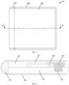
- FIG. 3 illustrates a second schematic structural diagram of an electronic device in a folded state according to an embodiment of the present disclosure
- FIG. 4 illustrates a schematic structural diagram of the electronic device illustrated in FIG. 3 taken along a P-P direction.
- the housing assembly 200 may further include a first magnetic mechanism, such as a first magnetic mechanism 240, and a second magnetic mechanism, such as a second magnetic mechanism 250.
- the first magnetic mechanism 240 may be disposed on the first housing 210, for example, it may be realized by gluing, riveting, screwing, or other methods.
- the second magnetic mechanism 250 may be disposed on the second housing 220.
- a part of a projection of the second magnetic mechanism 250 on the first housing 210 overlaps with the first magnetic mechanism 240.
- the projection of the second magnetic mechanism 250 on the first housing 210 completely overlaps with the first magnetic mechanism 240, at this time, a size of the projection of the second magnetic mechanism 250 on the first housing 210 is the same as a size of the first magnetic mechanism 240; or only a part of the projection of the second magnetic mechanism 250 on the first housing 210 overlaps with the first magnetic mechanism 240.
- the housing assembly 200 may further include a driving mechanism 260, the driving mechanism 260 is connected to the second magnetic mechanism 250, and the driving mechanism 260 may be used to drive the second magnetic mechanism 250 to move to change a position of the second magnetic mechanism 250 and thereby to make the second magnetic mechanism 250 and the first magnetic mechanism 240 switch between a state of attracted together and a state of repelled to be separated from each other.
- a magnetism of the first magnetic mechanism 240 is opposite to that of the second magnetic mechanism 250, at this time, the first magnetic mechanism 240 and the second magnetic mechanism 250 are mutually attracted together, the first housing 210 and the second housing 220 are mutually attached together by an attractive force, and the first housing 210 and the second housing 220 are kept in the folded state.
- the electronic device 20 can control the driving mechanism 260 to drive the second magnetic mechanism 250 to move to change the magnetism of the second magnetic mechanism 250 and the first magnetic mechanism 240 from the same to the opposite, at this time, a repulsive force is generated between the first housing 210 and the second housing 220, therefore the first housing 210 and the second housing 220 are unfolded at a certain angle, which is convenient for the user to separate the first housing 210 and the second housing 220, at this time, the first housing 210 and the second housing 220 are switched from the folded state to the unfolded state.
- the electronic device 20 can control the driving mechanism 260 to drive the second magnetic mechanism 250 to move to change the magnetism of the second magnetic mechanism 250 and the first magnetic mechanism 240 from the opposite to the same, at this time, an attractive force is generated between the first housing 210 and the second housing 220, therefore the first housing 210 and the second housing 220 are mutually attached together and are not easily separated, at this time, the first housing 210 and the second housing 220 are switched from the unfolded state to the folded state.
- the electronic device 20 may further include a processor, the processor is electrically connected to the driving mechanism 260, and the processor may be used to control working states of the driving mechanism 260.
- the processor may be configured to control, based on different signals, the driving mechanism 260 to drive the second magnetic mechanism to move to different positions and thereby to have the first magnetic mechanism 240 and the second magnetic mechanism 250 mutually attracted together or mutually repelled to be separated from each other.
- the processor may receive a first signal and control, based on the first signal, the second magnetic mechanism 250 to move to a first position, at this time, an attractive force can be generated between the second magnetic mechanism 250 and the first magnetic mechanism 240, the second magnetic mechanism 250 and the first magnetic mechanism 240 are mutually attracted together, and the first housing 210 and the second housing 220 rotate relatively to each other in a direction of mutual attachment, and thus the first housing 210 and the second housing 220 are kept in the folded state.
- the processor may receive a second signal and control, based on the second signal, the second magnetic mechanism 250 to move to a second position, at this time, a repulsive force can be generated between the second magnetic mechanism 250 and the first magnetic mechanism 240, the second magnetic mechanism 250 and the first magnetic mechanism 240 are mutually repelled to be separated from each other, and the first housing 210 and the second housing 220 rotate relatively to each other in a direction of mutual separating, and thus the first housing 210 and the second housing 220 may unfolded at a certain angle.
- FIG. 5 illustrates a first schematic structural diagram of a first magnetic mechanism and a second magnetic mechanism mutually attracted together in the electronic device illustrated in FIG. 4
- FIG. 6 illustrates a first schematic structural diagram of the first magnetic mechanism and the second magnetic mechanism mutually repelled to be separated from each other in the electronic device illustrated in FIG. 4
- the first magnetic mechanism 240 may include at least two first magnetic elements 241 arranged side by side. Two adjacent first magnetic elements 241 of the at least two first magnetic elements 241 are adjacent to each other, and magnetic poles of the two adjacent first magnetic elements 241 are unlike magnetic poles, so as to make the two adjacent first magnetic elements 241 be mutually attracted together, i.e., attached to each other.
- the first magnetic mechanism 240 may include a first magnetic element 241a, a first magnetic element 241b, and a first magnetic element 241c arranged side by side.
- the first magnetic element 241a includes a first magnetic pole (such as a S pole illustrated in FIGS. 5 and 6 ) and a second magnetic pole (such as a N pole illustrated in FIGS. 5 and 6 ) with opposite magnetism.
- the first magnetic pole faces toward an outside of the first housing 210 from an inside of the first housing 210
- the second magnetic pole faces toward the inside of the first housing 210 from the outside of the first housing 210.
- the first magnetic element 241b includes a first magnetic pole and a second magnetic pole.
- the second magnetic pole of the first magnetic element 241b and the first magnetic pole of the first magnetic element 241a are adjacent to each other, and the first magnetic pole of the first magnetic element 241b and the second magnetic pole of the first magnetic element 241a are adjacent to each other, which can make the first magnetic element 241a and the first magnetic element 241b be mutually attracted together by an attractive force.
- the first magnetic element 241c includes a first magnetic pole and a second magnetic pole.
- the first magnetic pole of the first magnetic element 241c and the second magnetic pole of the first magnetic element 241b are adjacent to each other, and the second magnetic pole of the first magnetic element 241c and the first magnetic pole of the first magnetic element 241b are adjacent to each other, which can make the first magnetic element 241c and the first magnetic element 241b be mutually attracted together by an attractive force.
- the first magnetic element 241 may be a strip-shaped structure, and the first magnetic element 241 includes two opposite ends, the first magnetic pole may be formed at one of the two opposite ends, and the second magnetic pole may be formed at the other end. It should be noted that the first magnetic element 241 may also have other structures, such as a U-shaped structure.
- the second magnetic mechanism 250 includes at least two second magnetic elements 251 arranged side by side. Two adjacent second magnetic elements 251 of the at least two second magnetic elements 251 are adjacent to each other, and magnetic poles of one second magnetic element 251 and the other second magnetic element 251 in the two adjacent second magnetic elements 251 are unlike magnetic poles to make the two adjacent second magnetic elements 251 be mutually attracted together.
- the embodiment of the present disclosure is exemplified by three second magnetic elements.
- the second magnetic mechanism 250 may include a second magnetic element 251a, a second magnetic element 251b, and a second magnetic element 251c arranged side by side.
- the second magnetic element 251a includes a third magnetic pole (such as a n pole illustrated in FIGS.
- the second magnetic element 251b includes a third magnetic pole and a fourth magnetic pole.
- the fourth magnetic pole of the second magnetic element 251b and the third magnetic pole of the second magnetic element 251a are adjacent to each other, and the third magnetic pole of the second magnetic element 251b and the third magnetic pole of the second magnetic element 251a are adjacent to each other, which can make the second magnetic element 251a and the second magnetic element 251b are mutually attracted together by an attractive force.
- the second magnetic element 251c includes a third magnetic pole and a fourth magnetic pole.
- the third magnetic pole of the second magnetic element 251c and the fourth magnetic pole of the second magnetic element 251b are adjacent to each other, and the fourth magnetic pole of the second magnetic element 251c and the fourth magnetic pole of the second magnetic element 251b are adjacent to each other, which can make the second magnetic element 251c and the second magnetic element 251b be mutually attracted together by an attractive force.
- the second magnetic element 251 may be a strip-shaped structure, the second magnetic element 251 includes two opposite ends, the third magnetic pole may be formed at one of the two opposite ends, and the fourth magnetic pole may be formed at the other end. It should be noted that the second magnetic element 251 may also have other structures, such as a U-shaped structure.
- the structure of the second magnetic element 251 of the second magnetic mechanism 250 may be the same as the structure of the first magnetic element 241 of the first magnetic mechanism 240; or the structures of the second magnetic element 251 and the first magnetic element 241 may be different.
- the number of the second magnetic elements 251 of the second magnetic mechanism 250 may be the same as or different from the number of the first magnetic elements 241 of the first magnetic mechanism 240.
- the number of the first magnetic elements 241 in the first magnetic mechanism 240 is one more than the number of the second magnetic elements 251 in the second magnetic mechanism 250.
- the number of the first magnetic elements 241 in the first magnetic mechanism 240 is four
- the number of the second magnetic elements 251 in the second magnetic mechanism 250 is three.
- the driving mechanism 260 drives the second magnetic mechanism 250 to move left or right in a direction parallel to the second housing 220, it can ensure that all the second magnetic elements 251 in the second magnetic mechanism 250 each have at least one the first magnetic element 241 corresponding thereto, during the movement of the second magnetic mechanism 250, all the second magnetic elements 251 can be in a working state, and the second magnetic elements 251 can be used better.
- the first magnetic elements 241 correspond to at least some of the second magnetic elements 251 one-to-one, magnetic poles of the first magnetic element 241 and the second magnetic element 251 corresponding thereto are unlike magnetic poles, an attractive force can be generated between the first magnetic mechanism 240 and the second magnetic mechanism 250 and thereby the first housing 210 and the second housing 220 are kept in the folded state.
- the electronic device 20 may control the driving mechanism 260 to drive the second magnetic elements 251 to move from the first position to the second position.
- the magnetic poles of the second magnetic element 251 and the first magnetic element 241 corresponding thereto are unlike magnetic poles, and the first magnetic mechanism 240 and the second magnetic mechanism 250 are mutually attracted together.
- the magnetic poles of the second magnetic element 251 and the first magnetic element 241 corresponding thereto are like magnetic poles, at this time, the first magnetic mechanism 240 and the second magnetic mechanism 250 are mutually repelled to be separated from each other.
- the first magnetic element 241a corresponds to the second magnetic element 251a
- the first magnetic element 241b corresponds to the second magnetic element 251b
- the first magnetic element 241c corresponds to the second magnetic element 251c.
- the first magnetic element 241a may correspond to the second magnetic element 251b
- the second magnetic pole of the first magnetic element 241a correspond to the third magnetic pole of the second magnetic element 251b, that is, the second magnetic pole of the first magnetic element 241a and the third magnetic pole of the second magnetic element 251b are like magnetic poles, and a repulsive force can be generated between the like magnetic poles.
- the first magnetic element 241a may correspond to the other second magnetic elements 251.
- the electronic device 20 can control the driving mechanism 260 to drive the second magnetic elements 251 to move from the second position to the first position.
- the first magnetic mechanism 240 and the second magnetic mechanism 250 are switched from the state of being repelled to be separated from each other to the state of being attracted together, an attractive force can be generated between the first housing 210 and the second housing 220 to keep the first housing 210 and the second housing 220 to be attached to each other, which can facilitate the user to store the electronic device 20, and it is also possible to prevent the first housing 210 and the second housing 220 from being unfolded when the user does not need to do that to spoil the user experience.
- the first magnetic element 241a corresponds to the second magnetic element 251b
- the first magnetic element 241c corresponds to the second magnetic element 251c.
- the first magnetic element 241a corresponds to the second magnetic element 251a
- the first magnetic element 241b corresponds to the second magnetic element 251b
- the first magnetic element 241c corresponds to the second magnetic element 251c
- the second magnetic pole of the first magnetic element 241a corresponds to the fourth magnetic pole of the second magnetic element 251a
- the first magnetic pole of the first magnetic element 241b corresponds to the third magnetic pole of the second magnetic element 251b
- the second magnetic pole of the first magnetic element 241c corresponds to the fourth magnetic pole of the second magnetic element 251c
- the second magnetic pole of the first magnetic element 241a and the fourth magnetic pole of the second magnetic element 251a are unlike magnetic poles
- the first magnetic pole of the first magnetic element 241b and the third magnetic pole of the second magnetic element 251b are unlike magnetic poles
- the second magnetic pole of the first magnetic element 241c and the fourth magnetic pole of the second magnetic element 251c are unlike magnetic poles
- the two adjacent first magnetic elements 241 of at least two first magnetic elements 241 may also be spaced apart from each other.
- the two adjacent second magnetic elements 251 of at least two second magnetic elements 251 may also be spaced apart from each other.
- the two adjacent second magnetic elements 251 may be spaced apart from each other by a predetermined distance.
- the two adjacent first magnetic elements 241 of the at least two first magnetic elements 241 may be spaced apart from each other or may be abutted against each other.
- a thickness of the first magnetic element 241 is the same as a thickness of the second magnetic element 251.
- the driving mechanism 260 drives the second magnetic element 250 to move, the second magnetic element 250 can be driven to a position with one width of the second magnetic element 251. It can be understood that when the electronic device 20 needs to be in the folded state, the S pole of the first magnetic element 241 directly faces to the n pole of the second magnetic element 251, the N pole of the first magnetic element 241 directly faces to the s pole of the second magnetic element 251, and thus, the first magnetic mechanism 240 and the second magnetic mechanism 250 generate an attractive force to keep the electronic device 20 in the folded state.
- the electronic device 20 is automatically folded by the attractive force generated by the first magnetic mechanism 240 and the second magnetic mechanism 250.
- the second magnetic mechanism 250 is driven by the driving mechanism 260 to move a position, for example, a position where the second magnetic mechanism 250 can be moved by one width of the second magnetic member 251, thus the S pole of the first magnetic element 241 in the first magnetic mechanism 240 directly faces to the s pole of the second magnetic element 251 in the second magnetic mechanism 250, and the N pole of the first magnetic element 241 in the first magnetic mechanism 240 directly faces to the n pole of the second magnetic element 251 in the second magnetic mechanism 250.
- a repulsive force can be generated between the first magnetic mechanism 240 and the second magnetic mechanism 250 to keep the electronic device 20 unfold at a certain angle, and the user can manually unfold the device.
- the first magnetic mechanism 240 may include at least two first magnetic elements 241
- the second magnetic mechanism 250 may include one second magnetic element 251.
- the driving mechanism 260 may drive the second magnetic element 251 to move between the first position and the second position to have the first magnetic mechanism 240 and the second magnetic mechanism 250 switched between the state of being attracted together and the state of being repelled to be separated from each other.
- the first magnetic mechanism 240 may include a first magnetic element 241a and a first magnetic element 241b
- the second magnetic mechanism 250 may include a second magnetic element 251b.
- the second magnetic element 251b corresponds to the first magnetic element 241b
- the third magnetic pole of the second magnetic element 251b directly faces to the first magnetic pole of the first magnetic element 241b, and an attractive force is generated between the second magnetic element 251b and the first magnetic element 241b to attract the first magnetic mechanism 240 and the second magnetic mechanism together.
- the second magnetic element 251b When the second magnetic element 251b is located at the second position, the second magnetic element 251b corresponds to the first magnetic element 241a, at this time, the third magnetic pole of the second magnetic element 251a directly faces to the second magnetic pole of the first magnetic element 241a, and a repulsive force is generated between the second magnetic element 251a and the first magnetic element 241a to have the first magnetic mechanism 240 and the second magnetic mechanism 240 repelled to be separated from each other.
- the first magnetic mechanism 240 may include three first magnetic elements, namely, the first magnetic element 241a, the first magnetic element 241b, and the first magnetic element 241c as described above.
- the magnetic intensity of the first magnetic element 241a may be greater than that of the first magnetic element 241b and the first magnetic element 241c, and the magnetic intensity of the first magnetic element 241b may be greater than that of the first magnetic element 241c.
- the second magnetic mechanism 250 may include a second magnetic element 251b as described above.
- the electronic device 20 may control the driving mechanism 260 to drive the second magnetic element 251b to different positions to have the second magnetic element 251b faced to the first magnetic elements 241 with different magnetic intensities.
- the processor may control the driving mechanism 260 to drive the second magnetic element 251b to face the first magnetic element 241a or the first magnetic element 241c based on an angle value of the electronic device 20 that needs to be unfolded.
- the processor may control the driving mechanism 260 to drive the second magnetic element 251b to face the first magnetic element 241c.
- the processor may control the driving mechanism 260 to drive the second magnetic element 251b to face the first magnetic element 241a.
- the repulsive force or attractive force generated between the second magnetic element 251 and the first magnetic element 241 corresponding thereto is also different.
- the separating distance and the degree of attaching between the first housing 210 and the second housing 220 are also different, which can make folded modes of the foldable electronic device more diversified.
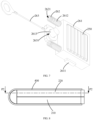
- FIG. 7 illustrates a schematic structural diagram of a driving mechanism and a second magnetic mechanism in the electronic device illustrated in FIG. 4 .
- FIG. 8 illustrates a third schematic structural diagram of an electronic device in a folded state according to an embodiment of the present disclosure.
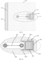
- FIG. 9 illustrates a schematic cross-sectional structural diagram of the electronic device illustrated in FIG. 8 taken along a P2-P2 direction.
- FIG. 10 illustrates a schematic structural diagram of an A area in the electronic device illustrated in FIG. 9 .
- the driving mechanism 260 may include a bracket 261 and a driving element.
- the bracket 261 is connected to the driving element.
- the second magnetic mechanism 250 is disposed on the bracket 261.
- the driving element is used to drive the bracket 261 to move to make the second magnetic mechanism 250 move following the bracket 261.
- the driving element may be a motor, a gear box, an electromagnet, or other mechanism that can provide a driving force.
- the bracket 261 is provided with a limit block such as a limit block 2611, the limit block 2611 cooperates with a limit groove such as a limit groove 225 provided on the second housing 220 to limit a movement direction of the bracket 261.
- the driving element can drive the bracket 261 to move.
- the limit groove 225 cooperates with the limit block 2611 to limit the movement trajectory of the bracket 261, therefore the second magnetic mechanism 250 provided on the bracket 261 can move according to a preset trajectory.
- the driving mechanism 260 may further include an elastic element such as an elastic element 262, an end of the elastic element 262 is connected to the bracket, another end of the elastic element 262 abuts against the second housing 220.
- the second housing 220 may include a case such as a case 226, which is accommodated inside the second housing 220.
- the case 226 is provided with a storage space in which the driving mechanism 260 and the second magnetic mechanism 250 are accommodated.
- the limit groove 225 is provided on the case 226.
- the end of the elastic element 262 is connected to the bracket 261, and another end of the elastic element 262 abuts against a side wall of the case 226.
- the driving element can control the bracket 261 to move in a first direction to a preset position, the second magnetic mechanism 250 moves following the bracket 261 in the first direction.
- the elastic element 262 is pressed, and at this time, the elastic element 262 is pressed to generate an elastic force.
- the electronic device 20 can cut off a power supply of the driving element, at this time, a driving force of the driving element disappears, and the elastic force of the pressed elastic element 262 is released, which can urge the bracket 261 to move to the original position in a second direction, and drive the second magnetic mechanism 250 to return to the original position.
- the structure of the driving mechanism according to the embodiment of the present disclosure can make the driving element work only once to realize the back-and-forth motion of the bracket 261, and can reduce the power consumption of the driving mechanism 260 to the electronic device 20.
- the first direction refers to a direction close to the side wall of the case 226 that abuts against the elastic element 262
- the second direction refers to a direction facing away from the side wall of the case 226 that abuts against the elastic element 262.
- the processor may be configured to control working states of the driving mechanism 260 based on different signals to make the first magnetic mechanism 240 and the second magnetic mechanism 250 be mutually attracted together or be mutually repelled to be separated from each other.
- the processor may receive a third signal and control, based on the third signal, the driving element to work.
- the driving element can drive the bracket 261 to move to the first position and press the elastic element 262, therefore the elastic element 262 is elastically deformed and in a compressed state.
- the processor may also receive a fourth signal and control, based on the fourth signal, the driving mechanism 260 not to work.
- the bracket 261 may be connected to the elastic element 262 through a first connection element such as the first connection element 2612.
- the first connection element 2612 may be provided on the side wall of the bracket 261 and protrude from the side wall of the bracket 261.
- the elastic element 262 may be provided with a first through hole such as the first through hole 2621. A portion of the elastic element 262 is sleeved on the first connection element 2612 through the first through hole 2621, and another portion of the elastic element 262 is exposed outside.
- the first connection element 2612 can limit the deformation direction of the elastic element 262, therefore the elastic element 262 can be deformed along an axial direction of the first connection element 2612 during the deformation, and can avoid the elastic element 262 from being deformed in other directions (such as in a radial direction of the elastic element 262).
- the number of the elastic element 262 in the embodiment of the present disclosure may be two.
- the number of the first connection element 2612 may be the same as the number of the elastic element 262.
- the two elastic elements 262 are spaced apart from each other and sleeved on the two first connection elements 2612 respectively.
- the arrangement of the two elastic elements 262 can equalize the force of the bracket 261, the bracket 261 does not deflect during the movement.
- the number of the elastic element 262 in the embodiment of the present disclosure can also be other values, such as one, three or four, and the embodiment of the present disclosure is not limited to this.
- the bracket 261 may further include a second connection element such as a second connection element 2613, the second connection element 2613 is arranged between the two first connection elements 2612, and the second connection element 2613 is used to connect with a towing element such as a towing element 263, which can generate a towing force under the driving of the driving element to tow the bracket 261 to move.
- the towing element 263 may include a second through hole such as a second through hole 2631, and the second connection element 2613 is sleeved in the second through hole 2631 to connect the towing element 263 with the second connection element 2613.
- FIG. 11 illustrates a second schematic structural diagram of a first magnetic mechanism and a second magnetic mechanism mutually attracted together in the electronic device illustrated in FIG. 4
- FIG. 12 illustrates a second schematic structural diagram of a first magnetic mechanism and a second magnetic mechanism mutually repelled to be separated from each other in the electronic device illustrated in FIG. 4
- the driving mechanism 260 may include a rotating shaft, such as a rotating shaft 264, which is connected to the second magnetic mechanism 250, and the driving element may drive the second magnetic mechanism 250 to rotate around the rotating shaft 264 to change a magnetic pole orientation of the second magnetic mechanism 250.
- the first magnetic pole of the first magnetic mechanism 240 faces toward the outside of the first housing 210 from the inside of the first housing 210
- the second magnetic pole of the first magnetic mechanism 240 faces toward the inside of the first housing 210 from the outside of the first housing 210.
- the driving element can drive the second magnetic mechanism 250 to rotate clockwise around the rotating shaft 264, so as to make the fourth magnetic pole of the second magnetic mechanism 250 be faced to the second magnetic pole of the first magnetic mechanism 240.
- the magnetic poles of the first magnetic mechanism 240 and the second magnetic mechanism 250 are unlike magnetic poles, the first magnetic mechanism 240 and the second magnetic mechanism 250 can generate the attractive force to make the electronic device 20 be kept in the folded state.
- the driving element can drive the second magnetic mechanism 250 to rotate counterclockwise around the rotating shaft 264, so as to make the third magnetic pole of the second magnetic mechanism 250 is faced to the second magnetic pole of the first magnetic mechanism 240.
- the magnetic poles of the first magnetic mechanism 240 and the second magnetic mechanism 250 are like magnetic poles, a repulsive force can be generated between the first magnetic mechanism 240 and the second magnetic mechanism 250 to make the electronic device 20 unfold at a certain angle, which facilitates the user to manually unfold the device.
- the driving element may drive the second magnetic mechanism 250 to rotate counterclockwise around the rotating shaft 264.
- the driving element may drive the second magnetic mechanism 250 to rotate clockwise around the rotating shaft 264.
- a rotating direction of the second magnetic mechanism 250 is not limited in the embodiments of the present disclosure, as long as the corresponding relationship between the magnetic poles of the second magnetic mechanism 250 and the magnetic poles of the first magnetic mechanism 240 can be changed, and thereby the first magnetic mechanism 240 and the second magnetic mechanism 250 can be switched between the state of being attracted together and the state of being repelled to be separated from each other.
- the first magnetic mechanism 240 when the electronic device 20 is in a horizontal folded mode, the first magnetic mechanism 240 may be disposed close to the second side 212, so as to make the first magnetic mechanism 240 be located at the side edge of the electronic device 20, therefore the user can easily unfold or fold the electronic device 20.
- the folded mode of the electronic device 20 may also be a vertical folded mode. If the electronic device 20 is vertically folded, the first magnetic mechanism 240 may be disposed close to the first side 211.
- the horizontal folded mode refers to a mode of folding along a length direction of the electronic device 20
- the vertical folded mode refers to a mode of folding along a width direction of the electronic device 20.
- the magnetic force of the first magnetic mechanism 240 can mainly act on the edge position of the first housing 210.
- the first housing 210 and the second housing 220 can be separated by a greater distance.
- the folded mode of the electronic device 20 is not limited to the horizontal folded mode and the vertical folded mode, for example, it may be a folded mode at any other angle.
- the electronic device 20 may further include a foldable display screen such as a foldable display screen 400, which may adopt a flexible organic light emitting diode (OLED) display screen, a flexible liquid crystal display (LCD), or other types of foldable display screens.
- the foldable display screen 400 is used to show a screen.
- the foldable display screen 400 may have a regular shape, such as a rectangular parallelepiped structure or a rounded rectangular structure, and the foldable display screen 400 may also have an irregular shape.
- the foldable display screen 400 may be exposed outside the first housing 210 and the second housing 220, or may be hidden inside the first housing 210 and the second housing 220.
Landscapes
- Engineering & Computer Science (AREA)
- Theoretical Computer Science (AREA)
- Computer Hardware Design (AREA)
- Physics & Mathematics (AREA)
- General Physics & Mathematics (AREA)
- Human Computer Interaction (AREA)
- General Engineering & Computer Science (AREA)
- Microelectronics & Electronic Packaging (AREA)
- Power Engineering (AREA)
- Electromagnetism (AREA)
- Signal Processing (AREA)
- Telephone Set Structure (AREA)
- Casings For Electric Apparatus (AREA)
Applications Claiming Priority (2)
| Application Number | Priority Date | Filing Date | Title |
|---|---|---|---|
| CN202010398352.2A CN111445802A (zh) | 2020-05-12 | 2020-05-12 | 电子设备 |
| PCT/CN2021/084527 WO2021227689A1 (zh) | 2020-05-12 | 2021-03-31 | 电子设备 |
Publications (2)
| Publication Number | Publication Date |
|---|---|
| EP4145428A1 true EP4145428A1 (de) | 2023-03-08 |
| EP4145428A4 EP4145428A4 (de) | 2023-10-25 |
Family
ID=71652041
Family Applications (1)
| Application Number | Title | Priority Date | Filing Date |
|---|---|---|---|
| EP21803031.0A Withdrawn EP4145428A4 (de) | 2020-05-12 | 2021-03-31 | Elektronische vorrichtung |
Country Status (4)
| Country | Link |
|---|---|
| US (1) | US20230114840A1 (de) |
| EP (1) | EP4145428A4 (de) |
| CN (1) | CN111445802A (de) |
| WO (1) | WO2021227689A1 (de) |
Families Citing this family (13)
| Publication number | Priority date | Publication date | Assignee | Title |
|---|---|---|---|---|
| CN111445802A (zh) * | 2020-05-12 | 2020-07-24 | Oppo广东移动通信有限公司 | 电子设备 |
| CN114384971A (zh) * | 2020-10-19 | 2022-04-22 | 富泰华工业(深圳)有限公司 | 壳体组件及电子装置 |
| CN113539107B (zh) * | 2021-07-23 | 2023-09-19 | 上海天马微电子有限公司 | 一种显示装置 |
| CN115704418B (zh) * | 2021-08-12 | 2025-05-27 | 北京小米移动软件有限公司 | 铰链组件和电子设备 |
| CN114126283B (zh) * | 2021-11-09 | 2024-05-31 | 维沃移动通信有限公司 | 一种电子设备 |
| CN114338870B (zh) * | 2021-12-21 | 2024-12-17 | 维沃移动通信有限公司 | 一种电子设备及其控制方法 |
| CN114285921B (zh) * | 2021-12-30 | 2025-01-24 | 维沃移动通信有限公司 | 电子设备及控制方法 |
| CN114422629B (zh) * | 2022-01-20 | 2025-02-14 | 维沃移动通信有限公司 | 电子设备 |
| CN114206048B (zh) * | 2022-02-10 | 2022-08-12 | 荣耀终端有限公司 | 电子设备 |
| CN114520844A (zh) * | 2022-02-22 | 2022-05-20 | 维沃移动通信有限公司 | 电子设备 |
| CN116581070B (zh) * | 2023-04-14 | 2025-10-03 | 中润新能源(徐州)有限公司 | 硅片智能长寿命输送装置 |
| CN120035065A (zh) * | 2023-11-22 | 2025-05-23 | 华为技术有限公司 | 壳体组件和折叠屏设备 |
| CN119767541B (zh) * | 2025-01-03 | 2025-11-18 | 苏州元脑智能科技有限公司 | 电路板切割装置 |
Family Cites Families (14)
| Publication number | Priority date | Publication date | Assignee | Title |
|---|---|---|---|---|
| CN2760726Y (zh) * | 2004-12-06 | 2006-02-22 | 金宝电子工业股份有限公司 | 可折叠式电子装置的磁性开关与可折叠式电子装置 |
| US7775567B2 (en) * | 2005-12-13 | 2010-08-17 | Apple Inc. | Magnetic latching mechanism |
| US20100283270A1 (en) * | 2009-05-07 | 2010-11-11 | Dell Products L.P. | Magnetic Latch and Method for Manufacture Thereof |
| US8705229B2 (en) * | 2012-04-25 | 2014-04-22 | Hewlett-Packard Development Company, L.P. | Foldable electronic devices including a first and a second magnet |
| CN205193667U (zh) * | 2015-11-18 | 2016-04-27 | 联想(北京)有限公司 | 电子设备 |
| CN107291164B (zh) * | 2017-06-30 | 2020-05-26 | 联想(北京)有限公司 | 启闭组件及电子设备 |
| US10653026B2 (en) * | 2018-01-08 | 2020-05-12 | Intel Corporation | Coupling systems and methods for electronic devices |
| KR102488408B1 (ko) * | 2018-06-22 | 2023-01-16 | 삼성전자주식회사 | 자성체를 포함하는 전자 장치 |
| CN110718145B (zh) * | 2018-07-13 | 2025-03-25 | 北京小米移动软件有限公司 | 屏幕组件及电子设备 |
| CN110718152B (zh) * | 2019-10-21 | 2022-04-12 | Oppo广东移动通信有限公司 | 折叠屏组件和移动终端 |
| CN110913628B (zh) * | 2019-12-06 | 2022-04-15 | Oppo广东移动通信有限公司 | 壳体组件和可折叠电子设备 |
| CN111131568B (zh) * | 2019-12-23 | 2021-07-16 | 华为技术有限公司 | 电子设备 |
| CN111028689B (zh) * | 2019-12-24 | 2022-05-31 | 闻泰通讯股份有限公司 | 折叠控制方法、装置、设备和介质 |
| CN111445802A (zh) * | 2020-05-12 | 2020-07-24 | Oppo广东移动通信有限公司 | 电子设备 |
-
2020
- 2020-05-12 CN CN202010398352.2A patent/CN111445802A/zh active Pending
-
2021
- 2021-03-31 EP EP21803031.0A patent/EP4145428A4/de not_active Withdrawn
- 2021-03-31 WO PCT/CN2021/084527 patent/WO2021227689A1/zh not_active Ceased
-
2022
- 2022-10-31 US US18/051,513 patent/US20230114840A1/en not_active Abandoned
Also Published As
| Publication number | Publication date |
|---|---|
| EP4145428A4 (de) | 2023-10-25 |
| CN111445802A (zh) | 2020-07-24 |
| WO2021227689A1 (zh) | 2021-11-18 |
| US20230114840A1 (en) | 2023-04-13 |
Similar Documents
| Publication | Publication Date | Title |
|---|---|---|
| US20230114840A1 (en) | Electronic device | |
| US11381725B2 (en) | Electronic devices and method for controlling camera module | |
| CN113438402B (zh) | 可伸缩摄像头组件及电子设备 | |
| US11516405B2 (en) | Electronic devices and method for controlling camera module | |
| US10812698B1 (en) | Camera assembly and electronic device | |
| KR102508070B1 (ko) | 힌지 구조 및 접이식 전자 기기 | |
| CN108520701B (zh) | 一种可折叠屏的支撑保护机构及移动终端 | |
| US11500271B2 (en) | Gimbal photographing device | |
| US10057998B1 (en) | Flexible display device | |
| EP3518509B1 (de) | Kameraanordnung und elektronische vorrichtung | |
| CN110149424B (zh) | 电子设备 | |
| CN113489814B (zh) | 电子设备 | |
| CN115643331B (zh) | 折叠机构和电子设备 | |
| US12105556B2 (en) | Terminal device | |
| US12393104B2 (en) | Electronic device and camera module thereof having a driver that drives a slider to move, a lens component rotating with movement of the slider | |
| US8078238B2 (en) | Electronic device | |
| CN115801939A (zh) | 电子设备 | |
| KR20220077929A (ko) | 전자기기 | |
| CN110166656B (zh) | 电子设备 | |
| CN109995905B (zh) | 功能组件、电子装置及电子装置的控制方法 | |
| CN110166658B (zh) | 摄像头组件与电子设备 | |
| US12395579B2 (en) | Display device | |
| KR102569731B1 (ko) | 멀티 폴더블 표시장치 | |
| KR100350663B1 (ko) | 렌티큘러판을 이용한 광고판 | |
| US20250155939A1 (en) | Foldable apparatus and electronic device |
Legal Events
| Date | Code | Title | Description |
|---|---|---|---|
| STAA | Information on the status of an ep patent application or granted ep patent |
Free format text: STATUS: THE INTERNATIONAL PUBLICATION HAS BEEN MADE |
|
| PUAI | Public reference made under article 153(3) epc to a published international application that has entered the european phase |
Free format text: ORIGINAL CODE: 0009012 |
|
| STAA | Information on the status of an ep patent application or granted ep patent |
Free format text: STATUS: REQUEST FOR EXAMINATION WAS MADE |
|
| 17P | Request for examination filed |
Effective date: 20221130 |
|
| AK | Designated contracting states |
Kind code of ref document: A1 Designated state(s): AL AT BE BG CH CY CZ DE DK EE ES FI FR GB GR HR HU IE IS IT LI LT LU LV MC MK MT NL NO PL PT RO RS SE SI SK SM TR |
|
| DAV | Request for validation of the european patent (deleted) | ||
| DAX | Request for extension of the european patent (deleted) | ||
| REG | Reference to a national code |
Ref country code: DE Ref legal event code: R079 Free format text: PREVIOUS MAIN CLASS: G09F0009300000 Ipc: G06F0001160000 |
|
| A4 | Supplementary search report drawn up and despatched |
Effective date: 20230926 |
|
| RIC1 | Information provided on ipc code assigned before grant |
Ipc: H05K 5/02 20060101ALI20230920BHEP Ipc: H04M 1/02 20060101ALI20230920BHEP Ipc: G09F 9/30 20060101ALI20230920BHEP Ipc: G06F 1/16 20060101AFI20230920BHEP |
|
| STAA | Information on the status of an ep patent application or granted ep patent |
Free format text: STATUS: THE APPLICATION HAS BEEN WITHDRAWN |
|
| 18W | Application withdrawn |
Effective date: 20240104 |