EP4145644A1 - Fiche audio - Google Patents
Fiche audio Download PDFInfo
- Publication number
- EP4145644A1 EP4145644A1 EP22193511.7A EP22193511A EP4145644A1 EP 4145644 A1 EP4145644 A1 EP 4145644A1 EP 22193511 A EP22193511 A EP 22193511A EP 4145644 A1 EP4145644 A1 EP 4145644A1
- Authority
- EP
- European Patent Office
- Prior art keywords
- ring
- section
- cables
- diameter
- head
- Prior art date
- Legal status (The legal status is an assumption and is not a legal conclusion. Google has not performed a legal analysis and makes no representation as to the accuracy of the status listed.)
- Granted
Links
Images



Classifications
-
- H—ELECTRICITY
- H01—ELECTRIC ELEMENTS
- H01R—ELECTRICALLY-CONDUCTIVE CONNECTIONS; STRUCTURAL ASSOCIATIONS OF A PLURALITY OF MUTUALLY-INSULATED ELECTRICAL CONNECTING ELEMENTS; COUPLING DEVICES; CURRENT COLLECTORS
- H01R24/00—Two-part coupling devices, or either of their cooperating parts, characterised by their overall structure
- H01R24/58—Contacts spaced along longitudinal axis of engagement
-
- H—ELECTRICITY
- H01—ELECTRIC ELEMENTS
- H01R—ELECTRICALLY-CONDUCTIVE CONNECTIONS; STRUCTURAL ASSOCIATIONS OF A PLURALITY OF MUTUALLY-INSULATED ELECTRICAL CONNECTING ELEMENTS; COUPLING DEVICES; CURRENT COLLECTORS
- H01R13/00—Details of coupling devices of the kinds covered by groups H01R12/70 or H01R24/00 - H01R33/00
- H01R13/56—Means for preventing chafing or fracture of flexible leads at outlet from coupling part
- H01R13/565—Torsion-relieving
-
- H—ELECTRICITY
- H01—ELECTRIC ELEMENTS
- H01R—ELECTRICALLY-CONDUCTIVE CONNECTIONS; STRUCTURAL ASSOCIATIONS OF A PLURALITY OF MUTUALLY-INSULATED ELECTRICAL CONNECTING ELEMENTS; COUPLING DEVICES; CURRENT COLLECTORS
- H01R13/00—Details of coupling devices of the kinds covered by groups H01R12/70 or H01R24/00 - H01R33/00
- H01R13/58—Means for relieving strain on wire connection, e.g. cord grip, for avoiding loosening of connections between wires and terminals within a coupling device terminating a cable
- H01R13/5804—Means for relieving strain on wire connection, e.g. cord grip, for avoiding loosening of connections between wires and terminals within a coupling device terminating a cable comprising a separate cable clamping part
- H01R13/5816—Means for relieving strain on wire connection, e.g. cord grip, for avoiding loosening of connections between wires and terminals within a coupling device terminating a cable comprising a separate cable clamping part for cables passing through an aperture in a housing wall, the separate part being captured between cable and contour of aperture
-
- H—ELECTRICITY
- H01—ELECTRIC ELEMENTS
- H01R—ELECTRICALLY-CONDUCTIVE CONNECTIONS; STRUCTURAL ASSOCIATIONS OF A PLURALITY OF MUTUALLY-INSULATED ELECTRICAL CONNECTING ELEMENTS; COUPLING DEVICES; CURRENT COLLECTORS
- H01R11/00—Individual connecting elements providing two or more spaced connecting locations for conductive members which are, or may be, thereby interconnected, e.g. end pieces for wires or cables supported by the wire or cable and having means for facilitating electrical connection to some other wire, terminal, or conductive member, blocks of binding posts
- H01R11/11—End pieces or tapping pieces for wires, supported by the wire and for facilitating electrical connection to some other wire, terminal or conductive member
-
- H—ELECTRICITY
- H01—ELECTRIC ELEMENTS
- H01R—ELECTRICALLY-CONDUCTIVE CONNECTIONS; STRUCTURAL ASSOCIATIONS OF A PLURALITY OF MUTUALLY-INSULATED ELECTRICAL CONNECTING ELEMENTS; COUPLING DEVICES; CURRENT COLLECTORS
- H01R2105/00—Three poles
-
- H—ELECTRICITY
- H01—ELECTRIC ELEMENTS
- H01R—ELECTRICALLY-CONDUCTIVE CONNECTIONS; STRUCTURAL ASSOCIATIONS OF A PLURALITY OF MUTUALLY-INSULATED ELECTRICAL CONNECTING ELEMENTS; COUPLING DEVICES; CURRENT COLLECTORS
- H01R4/00—Electrically-conductive connections between two or more conductive members in direct contact, i.e. touching one another; Means for effecting or maintaining such contact; Electrically-conductive connections having two or more spaced connecting locations for conductors and using contact members penetrating insulation
- H01R4/02—Soldered or welded connections
- H01R4/021—Soldered or welded connections between two or more cables or wires
-
- H—ELECTRICITY
- H01—ELECTRIC ELEMENTS
- H01R—ELECTRICALLY-CONDUCTIVE CONNECTIONS; STRUCTURAL ASSOCIATIONS OF A PLURALITY OF MUTUALLY-INSULATED ELECTRICAL CONNECTING ELEMENTS; COUPLING DEVICES; CURRENT COLLECTORS
- H01R4/00—Electrically-conductive connections between two or more conductive members in direct contact, i.e. touching one another; Means for effecting or maintaining such contact; Electrically-conductive connections having two or more spaced connecting locations for conductors and using contact members penetrating insulation
- H01R4/02—Soldered or welded connections
- H01R4/023—Soldered or welded connections between cables or wires and terminals
Definitions
- the present invention relates to the audiovisual field, and relates in particular to an audio plug with several cables.
- Audio plugs are widely used in the audiovisual field and in particular for music.
- Audio plugs are application specific. Most of the time, audio plugs allow only one cable to be connected. There are thus audio plugs for mono application, the audio plug having a single mono cable, and audio plugs for stereo application, the audio plug having a single stereo cable. Some audio plugs, however, allow two cables to be connected to a single plug simultaneously for hybrid applications, where an audio plug for stereo application has two mono cables (so-called Y or insert type configuration) connected at the other end to two audio plugs for a mono app.
- the present invention aims to overcome this drawback and relates to an audio plug configured to attach to the end of at least two audio cables, the audio plug comprising a head and a body configured to attach to the head, the head comprising an audio connector part and connection terminals configured to connect the audio connector part to the at least two audio cables, a through opening being formed in a longitudinal direction through the body between the upstream end of the side body head, carrying means for fixing to the head, and the downstream end, the through opening corresponding to the internal surface of the body having a symmetry of revolution around the longitudinal direction and being configured to allow the passage of the at least two cables through the body from the downstream end to the connection terminals at the upstream end, characterized in that a shoulder is further formed on the inner surface of the body to form two rotationally symmetrical sections in the body , a first cylindrical section on the upstream side and a second section with rotational symmetry on the downstream side, the audio plug further comprising a ring whose outer surface has a shoulder to form two adjoining sections, a first cylindrical section
- the audio plug comprises a head and a body configured to be fixed on the head, the head comprising a part forming an audio connector and connection terminals configured to connect the part forming an audio connector to the at least two cables audio, a through-opening being formed in a longitudinal direction through the body between the upstream end of the head-side body, carrying means for attachment to the head, and the downstream end, the through-opening corresponding to the internal surface of the body having rotational symmetry around the longitudinal direction and being configured to allow passage of the at least two cables through the body from the downstream end to the connection terminals at the upstream end, a shoulder being further formed on the inner surface of the body to form two cylindrical sections in the body, a first upstream side cylindrical section and a second cylindrical section c downstream from smaller in diameter than the first cylindrical section on the upstream side, the audio plug further comprising a ring whose outer surface has a shoulder to form two adjoining cylindrical sections, a first section with a diameter corresponding to the diameter of the first cylindrical section on the upstream side
- the body is fixed on the head preferably by screwing.
- the body can also be clipped onto the head, without departing from the scope of the present invention.
- the purpose of the ring according to the invention is to prevent any tendency to torsion (winding up) of the cables one on the other, or even any separation (lateral movements) of the cables during the closing phase of the connector (screwing of the body) or during subsequent handling of the plug and cable assembly. These movements are detrimental to the integrity of the solder points between the cables and the solder terminals of the plug head.
- the blocking member is an oblong opening formed in at least one of the first section and of the second section of the ring, the oblong shape having a major axis and a minor axis, the minor axis corresponding to the diameter of the cables.
- the blocking member may be a triangular-shaped opening, each side of the triangle having a length corresponding substantially to twice the diameter of the cables, or an oblong or slot-like shape having a major axis and a minor axis, the minor axis corresponding to the diameter of the cables, in order to guarantee locking of the three cables in the opening.
- the body is cylindrical.
- the body may however have any other external shape, such as for example a square section, without departing from the scope of the present invention.
- the second section with symmetry of revolution on the downstream side of the body and the second section of the ring are cylindrical.
- the second section with symmetry of revolution on the downstream side of the body comprises a part of constant diameter, smaller than the diameter of the first cylindrical section on the upstream side of the body, and a part with decreasing diameter of the part of constant diameter towards the cable end of the body, the second section the ring correspondingly comprising a constant diameter part and a decreasing diameter part from the constant diameter part towards the end of the ring, at least two openings being further formed in the side wall of the decreasing diameter part to form jaws, such that when the ring is pressed into the body, the inner wall of the decreasing diameter part exerts pressure on the jaws to bring the jaws together.
- claws are formed inside the jaws.
- the audio plug 1 of conventional structure, comprises a cylindrical body 2 to which is attached a head 3 carrying the audio connector, the body 2 making it possible to connect the head 3 to two cables 4a and 4b opposite the head 3 with respect to to the body 2.
- the body 2 carries on its outer face a groove 2c, serving to improve the gripping of the body 2, whether for the operations of mounting the audio plug 1 described later or for gripping the audio plug 1 a times mounted.
- a groove 2c serving to improve the gripping of the body 2, whether for the operations of mounting the audio plug 1 described later or for gripping the audio plug 1 a times mounted.
- Other surface patterns can however be envisaged instead of the groove 2c, such as for example the formation of a surface effect of the knurling type (knurling in English), always with the aim of creating friction with the fingers to better grip.
- the head 3 comprises a sheath 5 carrying a thread 5a configured to fix the sheath 5 by screwing into a corresponding internal thread 2a of the body 2, the body 2 coming into abutment at the end of screwing on the sheath 5 with a collar 5b formed on the sheath 5 attached to the thread 5a, the flange 5b having substantially the same diameter as the body 2.
- a cone 6 In the sheath 5 are assembled, in order from the free end of the head 3 to the left on the Figure 1 , a cone 6; a first insulating ring 7; a cylindrical intermediate ring 8 of the same diameter as the sheath 5; a second insulating ring 9 having a flange 9a on its outer periphery, substantially of the same diameter as the diameter of the sheath 5; a mass 10, the mass 10 being constituted by a washer 10a in which is formed a central hole 10b, a tab 10c extending perpendicularly to the plane of the washer 10a from one edge of the washer 10a, a hole 10d being formed at the end of the tab 10c; a third insulating ring 11, comprising a cylindrical core 11a on which is formed a collar 11b, a cutout 11c of the same width as the tongue 10c being formed on the collar 11b; and a spacer 12 of frustoconical shape in which a cylindrical chamber 12a is formed.
- the sheath 13 and the connector shaft 14 are also mounted in the head 3, the connector shaft 14 comprising a first connection end 14a intended to be connected to the cone 6 and a second connection end 14b intended to be connected to cables 4a and 4b.
- the second connection end 14b of the connector shaft 14 is a cylindrical abutment of larger diameter than the diameter of the connector shaft 14, configured to fit into the cylindrical chamber 12a formed in the spacer 12.
- clamp 13a is formed at one end of sheath 13, comprising two jaws intended to cooperate with first insulating ring 7.
- a tongue 13b extends from the other end of sheath 13, tongue 13b having an oblique recess 13c extending a tab 13d at the end of which a hole 13e is formed.
- the connector pin 14 is introduced by its second connection end 14b into the cylindrical chamber 12a of the spacer 12, then are successively mounted on the connector pin 14, by its first connection end 14a, sleeve 13; the third insulating ring 11; the mass 10, the hole 10b of the washer 10a engaging on the core of the third insulating ring 11 and the tongue 10c of the mass 10 passing in the cutout 11c of the third insulating ring 11 diametrically opposite to the tongue 13b of the sheath 13; the sheath 5; the second insulating ring 9; the intermediate ring 8, the flange 9a of the second insulating ring 9 being interposed between the sheath 5 and the intermediate ring 8; the first insulating ring 7, which hooks with the clamp 13a of the sheath 13; and cone 6.
- the cables 4a and 4b each have two terminals, respectively 4a+, 4a-, 4b+, 4b-, the terminals 4a- and 4b- being respectively connected to the tongue 10c of the mass 10 (acting as a terminal) and to the tab 13d of the scabbard 13 (acting as a terminal), the terminals 4a+ and 4b+ being connected to the connector shaft 14 (also acting as a terminal).
- terminals 4a- and 4b- can be simultaneously connected to tab 10c of ground 10, terminals 4a+ and 4b+ being respectively connected to lug 13d of sheath 13 and to connector shaft 14.
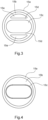
- the anti-torsion element 15 is a ring, described in more detail on the Figures 3 and 4 .
- the anti-torsion element 15 is a ring which comprises two joined cylindrical sections of the same axis formed in one piece, a first section 15a of larger diameter intended, once mounted in the plug 1, to be turned towards the head 3, and a second section 15b, of smaller diameter, intended to be turned towards the cables 4a and 4b once mounted in plug 1.
- a shoulder 2b is formed inside the body 2, such that the diameter of the section 15a corresponds to the internal diameter of the body 2 before the shoulder and the diameter of the section 15b corresponds to the internal diameter of the body 2 after the shoulder, forming a shoulder 15f on the outer surface of the ring 15 between the sections 15a and 15b.
- the body 2 in which the ring 15 is inserted is placed on the cables 4a and 4b before the assembly of the head 3 on the body as indicated above.
- a flange 15c of substantially oblong shape, consisting of two semicircles joined by straight lines, is formed in the second section 15b by two parallel cords 15d, the flange 15c having a width corresponding substantially to twice the section of a cable and a height corresponding substantially to the diameter of a cable in order to wedge the two cables 4a, 4b joined in the flange 15c.
- the ring 15 thus guarantees that the cables 4a, 4b will not move in relation to to the head 3.
- soldering/connecting the cables 4a, 4b are envisaged within the scope of the present invention.
- the slots 15e formed in the second section 15b between the strings 15d and the periphery of the second section 15b allow material savings.
- the shape of the flange 15 in the figures is not intended to limit the scope of the invention. Any cross-sectional shape capable of maintaining the two cables joined together is envisaged within the scope of the present invention. Thus a rectangular shape is envisaged within the scope of the present invention. It is also not necessary for the strings 15d to be complete: lugs projecting in the direction of the strings 15d but not meeting are also envisaged within the scope of the present invention.
- the audio plug 101 comprises a body 102, the sheath 105 and the ring 115.
- the body 102 carries on its external face a groove 102c, serving to improve the gripping of the body 102, whether for the operations of mounting the audio plug 101 or for gripping the audio plug 101 once mounted.
- a groove 102c serving to improve the gripping of the body 102, whether for the operations of mounting the audio plug 101 or for gripping the audio plug 101 once mounted.
- other surface patterns can however be envisaged instead of the groove 102c, such as for example the formation of a surface effect of the knurling type (knurling in English), always with the aim to create friction with the fingers for a better grip.
- the body 102 comprises a shoulder 102b formed on the internal surface of the body 102 to form two cylindrical sections in the body 102, a first cylindrical section 102d on the sleeve 105 side and a second cylindrical section 102e on the downstream side (cables) of smaller diameter than the first cylindrical section 102d on the upstream side.
- a thread 102a is formed on the end of the body 102 on the sleeve 105 side to cooperate by screwing with the thread 105a formed behind the collar 105b formed on the sleeve 105.
- the internal surface of the body 102 in the internal section of smaller diameter 102e, comprises a first part of fixed diameter 102f and a second part 102g of diameter tightening up to the end on the cable side, the internal surface of the body 102 keeping a symmetry of revolution around its longitudinal axis (from left to right on the Figure 5 ).
- Two openings 115i formed on the side surface of part 115h of ring 115 form two jaws 115j, so that when body 102 is screwed onto sleeve 105, with ring 115 inserted into body 102, the internal wall of the part 102e of the body 102 presses lightly on the jaws 115j to tighten them on the cables and thus hold them better.
- this part of the ring could have more openings, to form at this end of the ring a deformable part tightening around the cables under the effect of the tapered part 102g of the internal wall of the body 102.
- Claws 115k can be formed in the jaws 115j to hold the cables even better, increasing the friction with the cables.
- a single claw 115k transverse to the direction of the cables has been represented in the jaws 115j, it is understood that other types of claws are possible.
- any surface increasing the friction for example a textured surface, several parallel transverse claws, discontinuous claws, are possible.
- the claws 115k face each other on the two jaws 115j, but they could also be offset from each other, or be in different numbers and positions on each jaw 115j, without depart from the scope of the present invention.
- a substantially oblong-shaped opening 115c is formed in the part 115b of the ring 115, again to hold the cables once the audio plug 101 has been fitted, the effect of holding the cables being accentuated in the second embodiment by the tightening obtained by the jaws 115j which frame the shape oblong 115c and by claws 115k.
- ribs 115l are formed in the direction of the depth of the ring 115 in the inner surface of the first large diameter part 115a of the ring 115, to save material.
- the ring 15 is preferably made of plastic material, for example polyethylene (PE), polypropylene (PP), polyvinyl chloride (PVC), polycarbonate (PC), nylon, injection molded in one piece. Other materials such as Teflon (registered trademark), metal, in particular aluminum, can also however be envisaged to form the ring 15.
- the body 2 is preferably made of metal (copper, steel, bronze, aluminum) , machined or injection molded in one piece. Other materials, such as plastic materials, can however also be envisaged to form the body 2.
- a ring according to the invention can be adapted to any type of plug on which at least two cables can be connected.
Landscapes
- Details Of Connecting Devices For Male And Female Coupling (AREA)
Abstract
Description
- La présente invention concerne le domaine audiovisuel, et porte en particulier sur une fiche audio à plusieurs câbles.
- Les fiches audio sont très utilisées dans le domaine audiovisuel et en particulier pour la musique.
- Les fiches audio sont spécifiques de l'application. La plupart du temps, les fiches audio ne permettent de connecter qu'un seul câble. Il existe ainsi des fiches audio pour application mono, la fiche audio ayant un seul câble mono, et des fiches audio pour application stéréo, la fiche audio ayant un seul câble stéréo. Certaines fiches audio permettent toutefois de connecter deux câbles à une même fiche simultanément pour des applications hybrides, où une fiche audio pour application stéréo a deux câbles mono (configuration dite de type Y ou insert) connectés à l'autre extrémité à deux fiches audio pour une application mono.
- Avec les fiches audio existantes, dans lesquelles un corps se visse sur une tête de fiche une fois le ou les câbles solidarisés sur la tête de fiche, la présence de plusieurs câbles peut conduire à une désolidarisation du ou des câbles de la tête de fiche, en raison du frottement du corps sur la surface extérieure des câbles lors du vissage du corps sur la tête de fiche, ou tout simplement en raison de mouvements relatifs (torsion, enroulement) des câbles les uns par rapport aux autres résultant de la manipulation ultérieure de l'ensemble fiche et câbles, ce qui conduit soit à une mauvaise connexion, soit à une déconnexion qui impose de dévisser le corps de la tête pour resolidariser le ou les câbles à la tête de fiche.
- La présente invention vise à surmonter cet inconvénient et porte sur une fiche audio configurée pour se raccorder à l'extrémité d'au moins deux câbles audio, la fiche audio comprenant une tête et un corps configuré pour se fixer sur la tête, la tête comprenant une partie formant connecteur audio et des bornes de connexion configurées pour raccorder la partie formant connecteur audio aux au moins deux câbles audio, une ouverture traversante étant formée selon une direction longitudinale à travers le corps entre l'extrémité amont du corps côté tête, portant des moyens de fixation à la tête, et l'extrémité aval, l'ouverture traversante correspondant à la surface interne du corps ayant une symétrie de révolution autour de la direction longitudinale et étant configurée pour permettre le passage des au moins deux câbles à travers le corps de l'extrémité aval jusqu'aux bornes de connexion à l'extrémité amont, caractérisée par le fait qu'un épaulement est en outre formé sur la surface interne du corps pour former deux sections à symétrie de révolution dans le corps, une première section cylindrique côté amont et une deuxième section à symétrie de révolution côté aval, la fiche audio comprenant en outre une bague dont la surface externe présente un épaulement pour former deux sections accolées, une première section cylindrique de diamètre correspondant au diamètre de la première section cylindrique côté amont du corps et une deuxième section de surface externe correspondant à la surface interne de la deuxième section à symétrie de révolution côté aval du corps, la bague présentant une ouverture traversante selon la direction longitudinale, au moins un organe de blocage étant formé sur la surface interne de la bague, ledit au moins un organe de blocage étant configuré pour bloquer les au moins deux câbles par rapport à la bague, la bague étant configurée pour s'insérer dans le corps pour recouvrir les extrémités des câbles raccordés aux bornes de connexion avant fixation du corps sur la tête.
- Selon un mode de réalisation particulier, la fiche audio comprend une tête et un corps configuré pour se fixer sur la tête, la tête comprenant une partie formant connecteur audio et des bornes de connexion configurées pour raccorder la partie formant connecteur audio aux au moins deux câbles audio, une ouverture traversante étant formée selon une direction longitudinale à travers le corps entre l'extrémité amont du corps côté tête, portant des moyens de fixation à la tête, et l'extrémité aval, l'ouverture traversante correspondant à la surface interne du corps ayant une symétrie de révolution autour de la direction longitudinale et étant configurée pour permettre le passage des au moins deux câbles à travers le corps de l'extrémité aval jusqu'aux bornes de connexion à l'extrémité amont, un épaulement étant en outre formé sur la surface interne du corps pour former deux sections cylindriques dans le corps, une première section cylindrique côté amont et une deuxième section cylindrique côté aval de plus petit diamètre que la première section cylindrique côté amont, la fiche audio comprenant en outre une bague dont la surface externe présente un épaulement pour former deux sections cylindriques accolées, une première section de diamètre correspondant au diamètre de la première section cylindrique côté amont du corps et une deuxième section de diamètre correspondant au diamètre de la deuxième section cylindrique côté aval du corps, la bague présentant une ouverture traversante selon la direction longitudinale, au moins un organe de blocage étant formé sur la surface interne de la bague, ledit au moins un organe de blocage étant configuré pour bloquer les au moins deux câbles par rapport à la bague, la bague étant configurée pour s'insérer dans le corps pour recouvrir les extrémités des câbles raccordés aux bornes de connexion avant fixation du corps sur la tête.
- Le corps se fixe sur la tête de préférence par vissage. En variante, le corps peut également se clipser sur la tête, sans s'éloigner du cadre de la présente invention.
- La bague selon l'invention a pour but d'empêcher toute tendance à la torsion (enroulement) des câbles l'un sur l'autre, ou encore toute séparation (mouvements latéraux) des câbles pendant la phase de fermeture du connecteur (vissage du corps) ou durant la manipulation ultérieure de l'ensemble fiche et câbles. Ces mouvements sont préjudiciables à l'intégrité des points de soudures entre les câbles et les cosses de soudure de la tête de fiche.
- Selon un mode de réalisation, l'organe de blocage est une ouverture oblongue formée dans au moins l'une de la première section et de la deuxième section de la bague, la forme oblongue ayant un grand axe et un petit axe, le petit axe correspondant au diamètre des câbles. Dans le cas de trois câbles, l'organe de blocage peut être une ouverture de forme triangulaire, chaque côté du triangle ayant une longueur correspondant sensiblement à deux fois le diamètre des câbles, ou une forme oblongue ou de type fente ayant un grand axe et un petit axe, le petit axe correspondant au diamètre des câbles, afin de garantir un blocage des trois câbles dans l'ouverture.
- Selon un mode de réalisation, le corps est cylindrique. Le corps peut toutefois avoir toute autre forme externe, comme par exemple à section carrée, sans s'éloigner du cadre de la présente invention.
- Selon un mode de réalisation, la deuxième section à symétrie de révolution côté aval du corps et la deuxième section de la bague sont cylindriques.
- Selon un mode de réalisation, la deuxième section à symétrie de révolution côté aval du corps comprend une partie de diamètre constant, inférieur au diamètre de la première section cylindrique côté amont du corps, et une partie à diamètre décroissant de la partie de diamètre constant vers l'extrémité côté câbles du corps, la deuxième section la bague comprenant de manière correspondante une partie à diamètre constant et une partie à diamètre décroissant de la partie à diamètre constant vers l'extrémité de la bague, au moins deux ouvertures étant en outre formées dans la paroi latérale de la partie à diamètre décroissant pour former des mâchoires, de telle sorte que lorsque la bague est enfoncée dans le corps, la paroi interne de la partie à diamètre décroissant exerce une pression sur les mâchoires pour rapprocher les mâchoires.
- Selon un mode de réalisation, des griffes sont formées à l'intérieur des mâchoires.
- Pour mieux illustrer l'objet de la présente invention, un mode de réalisation de celle-ci sera décrit ci-après en référence aux dessins annexés.
- Sur ces dessins :
- [
Fig. 1 ] est une vue en perspective éclatée d'une fiche audio équipée d'un élément anti-torsion selon un premier mode de réalisation de la présente invention ; - [
Fig. 2 ] est une vue en coupe de la fiche audio de laFigure 1 ; - [
Fig. 3 ] est une avant de l'élément anti-torsion du premier mode de réalisation ; - [
Fig. 4 ] est une vue arrière de l'élément anti-torsion du premier mode de réalisation ; - [
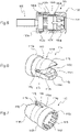
Fig. 5 ] est une vue en coupe analogue à laFigure 2 d'une fiche selon un deuxième mode de réalisation de l'invention ;[Fig. 6 ] est une vue en perspective arrière de l'élément anti-torsion du deuxième mode de réalisation ; - [
Fig. 7 ] est une vue en perspective avant de l'élément anti-torsion du deuxième mode de réalisation ; et - [
Fig. 8 ] est une vue arrière de l'élément anti-torsion du deuxième mode de réalisation . - Si l'on se réfère à la
Figure 1 et à laFigure 2 , on peut voir qu'il y est représenté une fiche audio 1 équipée d'un élément anti-torsion 15 selon un premier mode de réalisation de la présente invention. - La fiche audio 1, de structure classique, comprend un corps 2 cylindrique auquel est fixée une tête 3 portant le connecteur audio, le corps 2 permettant de relier la tête 3 à deux câbles 4a et 4b à l'opposé de la tête 3 par rapport au corps 2.
- Comme représenté, le corps 2 porte sur sa face externe une rainure 2c, servant à améliorer la préhension du corps 2, que ce soit pour les opérations de montage de la fiche audio 1 décrites plus loin ou pour la préhension de la fiche audio 1 une fois montée. D'autres motifs de surface peuvent toutefois être envisagés à la place de la rainure 2c, comme par exemple la formation d'un effet de surface de type moletage (knurling en anglais), toujours dans le but de créer des frottements avec les doigts pour une meilleure préhension.
- La tête 3 comprend un fourreau 5 portant un filetage 5a configuré pour fixer par vissage le fourreau 5 dans un taraudage 2a correspondant du corps 2, le corps 2 venant en butée en fin de vissage sur le fourreau 5 avec une collerette 5b formée sur le fourreau 5 accolée au filetage 5a, la collerette 5b ayant sensiblement le même diamètre que le corps 2.
- Dans le fourreau 5 sont assemblés, dans l'ordre depuis l'extrémité libre de la tête 3 à gauche sur la
Figure 1 , un cône 6 ; une première bague isolante 7 ; une bague intermédiaire 8 cylindrique et de même diamètre que le fourreau 5 ; une deuxième bague isolante 9 présentant une collerette 9a sur sa périphérie externe, sensiblement de même diamètre que le diamètre du fourreau 5 ; une masse 10, la masse 10 étant constituée par une rondelle 10a dans laquelle est formé un trou 10b central, une languette 10c s'étendant perpendiculairement au plan de la rondelle 10a depuis un bord de la rondelle 10a, un trou 10d étant formé à l'extrémité de la languette 10c ; une troisième bague isolante 11, comportant une âme cylindrique 11a sur laquelle est formée une collerette 11b, une découpe 11c de même largeur que la languette 10c étant formée sur la collerette 11b ; et une entretoise 12 de forme tronconique dans laquelle est formée une chambre cylindrique 12a. La première bague isolante 7, la deuxième bague isolante 9, la masse 10, la troisième bague isolante 11 et l'entretoise 12 présentent tous un percement central pour le passage d'un fourreau 13 et d'un axe de connecteur 14 comme cela est décrit ci-après. - Le fourreau 13 et l'axe de connecteur 14 sont en outre montés dans la tête 3, l'axe de connecteur 14 comprenant une première extrémité de connexion 14a destinée à se connecter au cône 6 et une seconde extrémité de connexion 14b destinée à se connecter aux câbles 4a et 4b. La seconde extrémité de connexion 14b de l'axe de connecteur 14 est une butée cylindrique de plus grand diamètre que le diamètre de l'axe de connecteur 14, configurée pour s'emboîter dans la chambre 12a cylindrique formée dans l'entretoise 12. Une pince 13a est formée à une extrémité du fourreau 13, comportant deux mâchoires destinées à coopérer avec la première bague isolante 7. Une languette 13b s'étend depuis l'autre extrémité du fourreau 13, la languette 13b présentant un décrochement oblique 13c se prolongeant par une patte 13d à l'extrémité de laquelle un trou 13e est formé.
- A l'état monté de la tête 3, l'axe de connecteur 14 est introduit par sa seconde extrémité de connexion 14b dans la chambre cylindrique 12a de l'entretoise 12, puis sont successivement montés sur l'axe de connecteur 14, par sa première extrémité de connexion 14a, le fourreau 13 ; la troisième bague isolante 11 ; la masse 10, le trou 10b de la rondelle 10a s'engageant sur l'âme de la troisième bague isolante 11 et la languette 10c de la masse 10 passant dans la découpe 11c de la troisième bague isolante 11 diamétralement opposée à la languette 13b du fourreau 13 ; le fourreau 5 ; la deuxième bague isolante 9 ; la bague intermédiaire 8, la collerette 9a de la deuxième bague isolante 9 s'interposant entre le fourreau 5 et la bague intermédiaire 8 ; la première bague isolante 7, qui s'accroche avec la pince 13a du fourreau 13 ; et le cône 6.
- Les câbles 4a et 4b possèdent chacun deux bornes, respectivement 4a+, 4a-, 4b+, 4b-, les bornes 4a- et 4b- étant respectivement connectées à la languette 10c de la masse 10 (faisant office de cosse) et à la patte 13d du fourreau 13 (faisant office de cosse), les bornes 4a+ et 4b+ étant connectées à l'axe de connecteur 14 (faisant également office de cosse).
- D'autres modes de connexion sont possibles. Par exemple, les bornes 4a- et 4b- peuvent être simultanément connectées à la languette 10c de la masse 10, les bornes 4a+ et 4b+ étant respectivement connectées à la patte 13d du fourreau 13 et à l'axe de connecteur 14.
- L'élément anti-torsion 15 est une bague, décrite plus en détail sur les
Figures 3 et 4 . - L'élément anti-torsion 15 est une bague qui comprend deux sections cylindriques de même axe accolées formées d'un seul tenant, une première section 15a de plus grand diamètre destinée, une fois montée dans la fiche 1, à être tournée vers la tête 3, et une seconde section 15b, de plus petit diamètre, destinée à être tournée vers les câbles 4a et 4b une fois montée dans la fiche 1.
- Comme on peut le voir sur la
Figure 2 , un épaulement 2b est formé à l'intérieur du corps 2, de telle sorte que le diamètre de la section 15a corresponde au diamètre interne du corps 2 avant l'épaulement et que le diamètre de la section 15b corresponde au diamètre interne du corps 2 après l'épaulement, formant un épaulement 15f sur la surface externe de la bague 15 entre les sections 15a et 15b. - En pratique, le corps 2 dans lequel est inséré la bague 15 est placé sur les câbles 4a et 4b avant le montage de la tête 3 sur le corps comme indiqué plus haut.
- La correspondance des diamètres internes du corps 2 et externe de la bague 15 permet, lors du vissage du corps 2, de tourner librement par rapport à la bague 15 coinçant l'ensemble comprenant les câbles 4a, 4b, la bague 15 et la tête 3, évitant ainsi une torsion des câbles 4a, 4b lors du montage de la fiche 1. Une bride 15c de forme sensiblement oblongue, constituée de deux demicercles réunis par des droites, est formée dans la seconde section 15b par deux cordes parallèles 15d, la bride 15c ayant une largeur correspondant sensiblement à deux fois la section d'un câble et une hauteur correspondant sensiblement au diamètre d'un câble afin de coincer les deux câbles 4a, 4b accolés dans la bride 15c.
- Une fois les câbles 4a, 4b soudés à l'axe de connecteur 14 d'une part, et à la masse 10 et au fourreau 13 d'autre part, la bague 15 garantit ainsi que les câbles 4a, 4b ne bougeront pas par rapport à la tête 3. Comme indiqué plus haut, d'autres possibilités de soudure/connexion des câbles 4a, 4b sont envisagées dans le cadre de la présente invention.
- Les lumières 15e formées dans la seconde section 15b entre les cordes 15d et la périphérie de la seconde section 15b permettent une économie de matière.
- Il est bien entendu que la forme de la bride 15 sur les figures n'est pas entendue limiter la portée de l'invention. Toute forme en coupe transversale apte à maintenir les deux câbles accolés est envisagée dans le cadre de la présente invention. Ainsi une forme rectangulaire est envisagée dans le cadre de la présente invention. Il n'est pas non plus nécessaire que les cordes 15d soient complètes : des ergots en saille selon la direction des cordes 15d mais ne se rejoignant pas sont aussi envisagés dans le cadre de la présente invention.
- Si l'on se réfère aux
Figures 5 à 7 , on peut voir que l'on a représenté une fiche 101 selon un deuxième mode de réalisation de la présente invention. - Afin de ne pas alourdir la description de ce deuxième mode de réalisation, seuls les éléments qui diffèrent par rapport au premier mode de réalisation sont décrits et représentés, à savoir le fourreau 105, le corps 102 et la bague 115, les autres éléments s'introduisant dans le fourreau 105 ainsi que les câbles étant identiques au premier mode de réalisation et donc non décrits ou représentés à nouveau.
- Dans ce deuxième mode de réalisation, la fiche audio 101 comprend un corps 102, le fourreau 105 et la bague 115.
- Comme pour le premier mode de réalisation, le corps 102 porte sur sa face externe une rainure 102c, servant à améliorer la préhension du corps 102, que ce soit pour les opérations de montage de la fiche audio 101 ou pour la préhension de la fiche audio 101 une fois montée. Comme dans le premier mode de réalisation, d'autres motifs de surface peuvent toutefois être envisagés à la place de la rainure 102c, comme par exemple la formation d'un effet de surface de type moletage (knurling en anglais), toujours dans le but de créer des frottements avec les doigts pour une meilleure préhension.
- Le corps 102 comprend un épaulement 102b formé sur la surface interne du corps 102 pour former deux sections cylindriques dans le corps 102, une première section cylindrique 102d côté fourreau 105 et une deuxième section cylindrique 102e côté aval (câbles) de plus petit diamètre que la première section cylindrique 102d côté amont.
- Un taraudage 102a est formé sur l'extrémité du corps 102 côté fourreau 105 pour coopérer par vissage avec le filetage 105a formé derrière la collerette 105b formée sur le fourreau 105.
- La principale différence avec le premier mode de réalisation, concernant le corps 102, est que la surface interne du corps 102, dans la section interne de plus petit diamètre 102e, comprend une première partie de diamètre fixe 102f et une seconde partie 102g de diamètre se resserrant jusqu'à l'extrémité côté câbles, la surface interne du corps 102 gardant une symétrie de révolution autour de son axe longitudinal (de gauche à droite sur la
Figure 5 ). - La bague 115 présente de manière correspondante deux parties :
- une première partie de grand diamètre 115a, destinée à se loger dans la première section cylindrique 102d côté fourreau 105 du corps 102, le diamètre externe de la première partie 115a de la bague 115 correspondant au diamètre interne de la première section cylindrique 102d côté fourreau 105 du corps 102, et- une seconde partie de plus petit diamètre 115b, présentant une partie 115g de diamètre fixe, destinée à se loger dans la première partie de diamètre fixe 102f de la seconde section cylindrique 102e côté câbles du corps 102, le diamètre externe de la partie 115g de la bague 115 correspondant au diamètre interne de la première partie de diamètre fixe 102d de la seconde section cylindrique 102e côté câbles du corps 102, et une partie 115h à diamètre décroissant depuis la partie 115g, destinée à venir se loger dans la partie 102g du corps 102, la première partie 115a et la seconde partie 115b étant séparées par un épaulement 115f.
- Deux ouvertures 115i formées sur la surface latérale de la partie 115h de la bague 115 forment deux mâchoires 115j, de telle sorte que lorsque le corps 102 est vissé sur le fourreau 105, avec la bague 115 insérée dans le corps 102, la paroi interne de la partie 102e du corps 102 appuie légèrement sur les mâchoires 115j pour les serrer sur les câbles et ainsi mieux les maintenir.
- Il est bien entendu que cette partie de la bague pourrait comporter plus d'ouvertures, pour former à cette extrémité de la bague une partie déformable se resserrant autour des câbles sous l'effet de la partie 102g effilée de la paroi interne du corps 102.
- Des griffes 115k peuvent être formées dans les mâchoires 115j pour encore mieux maintenir les câbles, en augmentant la friction avec les câbles. Bien qu'une seule griffe 115k transversale à la direction des câbles ait été représentée dans les mâchoires 115j, il est bien entendu que d'autres types de griffes sont envisageables. Ainsi, toute surface augmentant le frottement, par exemple une surface texturée, plusieurs griffes transversales parallèles, des griffes discontinues, sont envisageables.
- De même, les griffes 115k sont en vis-à-vis sur les deux mâchoires 115j, mais elles pourraient également être décalées l'une par rapport à l'autre, ou être en nombres et positions différentes sur chaque mâchoire 115j, sans pour autant s'éloigner du cadre de la présente invention.
- Comme pour le premier mode de réalisation, une ouverture de forme sensiblement oblongue 115c, bien qu'ouverte à ses extrémités longitudinales en raison des ouvertures 115i formées depuis les extrémités de la forme oblongue 115c vers l'extrémité côté câbles de la bague 115, est formée dans la partie 115b de la bague 115, toujours pour maintenir les câbles une fois la fiche audio 101 montée, l'effet de maintien des câbles étant accentué dans le deuxième mode de réalisation par le serrage obtenu par les mâchoires 115j qui encadrent la forme oblongue 115c et par les griffes 115k.
- Enfin, des nervures 115l sont formées dans le sens de la profondeur de la bague 115 dans la surface interne de la première partie de grand diamètre 115a de la bague 115, pour une économie de matière.
- La bague 15 est de préférence en matière plastique, par exemple en polyéthylène (PE), polypropylène (PP), polychlorure de vinyle (PVC), polycarbonate (PC), en nylon, moulée par injection d'un seul tenant. D'autres matières telles que du Téflon (marque enregistrée), du métal, notamment de l'aluminium, peuvent aussi toutefois être envisagées pour former la bague 15. Le corps 2 est de préférence en métal (cuivre, acier, bronze, aluminium), usiné ou moulé par injection d'un seul tenant. D'autres matières, telles que les matières plastiques, peuvent aussi toutefois être envisagées pour former le corps 2.
- L'invention n'est également pas limitée à la fiche particulière décrite en référence aux dessins. Une bague selon l'invention peut s'adapter à tout type de fiche sur laquelle au moins deux câbles peuvent être connectés.
Claims (6)
- - Fiche audio (1 ; 101) configurée pour se raccorder à l'extrémité d'au moins deux câbles audio (4a, 4b), la fiche audio (1 ; 101) comprenant une tête (3) et un corps (2) configuré pour se fixer sur la tête (3), la tête (3) comprenant une partie formant connecteur audio et des bornes de connexion configurées pour raccorder la partie formant connecteur audio aux au moins deux câbles audio (4a, 4b), une ouverture traversante étant formée selon une direction longitudinale à travers le corps (2 ; 102) entre l'extrémité amont du corps (2 ; 102) côté tête, portant des moyens de fixation à la tête (2a ; 102a), et l'extrémité aval, l'ouverture traversante correspondant à la surface interne du corps (2 ; 102) ayant une symétrie de révolution autour de la direction longitudinale et étant configurée pour permettre le passage des au moins deux câbles (4a, 4b) à travers le corps (2 ; 102) de l'extrémité aval jusqu'aux bornes de connexion à l'extrémité amont, caractérisée par le fait qu'un épaulement (2b ; 102b) est en outre formé sur la surface interne du corps (2 ; 102) pour former deux sections à symétrie de révolution dans le corps (2 ; 102), une première section cylindrique côté amont et une deuxième section à symétrie de révolution côté aval, la fiche audio (1 ; 101) comprenant en outre une bague (15 ; 115) dont la surface externe présente un épaulement (15f ; 115f) pour former deux sections accolées (15a, 15b ; 115a, 115b), une première section (15a ; 115a) cylindrique de diamètre correspondant au diamètre de la première section cylindrique côté amont du corps (2 ; 102) et une deuxième section (15b ; 115b) de surface externe correspondant à la surface interne de la deuxième section à symétrie de révolution côté aval du corps (2 ; 102), la bague (15 ; 115) présentant une ouverture traversante selon la direction longitudinale, au moins un organe de blocage (15c ; 115c) étant formé sur la surface interne de la bague (15 ; 115), ledit au moins un organe de blocage (15c ; 115c) étant configuré pour bloquer les au moins deux câbles (4a, 4b) par rapport à la bague (15; 115), la bague (15; 115) étant configurée pour s'insérer dans le corps (2 ; 102) pour recouvrir les extrémités des câbles (4a, 4b) raccordés aux bornes de connexion avant fixation du corps (2 ; 102) sur la tête (3).
- - Fiche audio (1 ; 101) selon la revendication 1, caractérisée par le fait que l'organe de blocage (15c ; 115c) est une ouverture oblongue formée dans au moins l'une de la première section (15a ; 115a) et de la deuxième section (15b ; 115b) de la bague (15 ; 155), la forme oblongue ayant un grand axe et un petit axe, le petit axe correspondant au diamètre des câbles (4a, 4b).
- - Fiche audio (1 ; 101) selon la revendication 2, caractérisée par le fait que le corps (2 ; 102) est cylindrique.
- - Fiche audio (1) selon l'une des revendications 1 à 3, caractérisée par le fait que la deuxième section à symétrie de révolution côté aval du corps (2) et la deuxième section (15b) de la bague sont cylindriques.
- - Fiche audio (101) selon l'une des revendications 1 à 3, caractérisée par le fait que la deuxième section à symétrie de révolution côté aval du corps (102) comprend une partie (102f) de diamètre constant, inférieur au diamètre de la première section cylindrique côté amont du corps (102), et une partie à diamètre décroissant (102g) de la partie (102f) de diamètre constant vers l'extrémité côté câbles du corps (102), la deuxième section (115b) la bague (115) comprenant de manière correspondante une partie à diamètre constant (115g) et une partie à diamètre décroissant (115h) de la partie à diamètre constant (115g) vers l'extrémité de la bague (115), au moins deux ouvertures étant en outre formées dans la paroi latérale de la partie à diamètre décroissant (115h) pour former des mâchoires (115j), de telle sorte que lorsque la bague (115) est enfoncée dans le corps (102), la paroi interne de la partie à diamètre décroissant (102g) exerce une pression sur les mâchoires (115j) pour rapprocher les mâchoires (115j).
- - Fiche audio (101) selon la revendication 5, caractérisée par le fait que des griffes (115k) sont formées à l'intérieur des mâchoires (115j).
Applications Claiming Priority (1)
| Application Number | Priority Date | Filing Date | Title |
|---|---|---|---|
| FR2109359A FR3126807B1 (fr) | 2021-09-07 | 2021-09-07 | Fiche audio |
Publications (3)
| Publication Number | Publication Date |
|---|---|
| EP4145644A1 true EP4145644A1 (fr) | 2023-03-08 |
| EP4145644B1 EP4145644B1 (fr) | 2024-06-12 |
| EP4145644C0 EP4145644C0 (fr) | 2024-06-12 |
Family
ID=78332900
Family Applications (1)
| Application Number | Title | Priority Date | Filing Date |
|---|---|---|---|
| EP22193511.7A Active EP4145644B1 (fr) | 2021-09-07 | 2022-09-01 | Fiche audio |
Country Status (4)
| Country | Link |
|---|---|
| US (1) | US12300947B2 (fr) |
| EP (1) | EP4145644B1 (fr) |
| CN (1) | CN115776016A (fr) |
| FR (1) | FR3126807B1 (fr) |
Families Citing this family (1)
| Publication number | Priority date | Publication date | Assignee | Title |
|---|---|---|---|---|
| DE102023117285A1 (de) * | 2023-06-30 | 2025-01-02 | Turck Holding Gmbh | Elektronische Baugruppe sowie Verfahren zur Herstellung einer elektronischen Baugruppe |
Citations (3)
| Publication number | Priority date | Publication date | Assignee | Title |
|---|---|---|---|---|
| US20140168528A1 (en) * | 2009-03-12 | 2014-06-19 | Samsung Electronics Co., Ltd. | Signal transfer apparatus |
| US20170004907A1 (en) * | 2015-07-02 | 2017-01-05 | Sumitomo Electric Industries, Ltd. | Multi-core cable |
| CN209766700U (zh) * | 2019-04-30 | 2019-12-10 | 吴丰廷 | 音讯接头及音讯传输装置 |
Family Cites Families (6)
| Publication number | Priority date | Publication date | Assignee | Title |
|---|---|---|---|---|
| US3370122A (en) | 1963-05-30 | 1968-02-20 | Ichikawa Mitsuji | Conduit and ground wire connected by a metal strap |
| FR2510311A1 (fr) | 1981-07-24 | 1983-01-28 | Sicame Sa | Raccord de prise de courant sur cable electrique |
| FR2550666B1 (fr) | 1983-08-11 | 1989-04-14 | Schaff Jean Paul | Dispositif de jonction electrique destine aux installations de protection parafoudre |
| US4891018A (en) | 1988-06-16 | 1990-01-02 | Minnesota Mining And Manufacturing Company | Solderless electrical connector |
| CN203631757U (zh) | 2013-10-28 | 2014-06-04 | 广州番禺电缆集团有限公司 | 一种夹持电缆线的方向平行的电缆线夹 |
| CN106099418B (zh) | 2016-07-06 | 2018-06-12 | 国网江西省电力有限公司九江供电分公司 | 一种绝缘穿刺线夹及其专用安装工具 |
-
2021
- 2021-09-07 FR FR2109359A patent/FR3126807B1/fr active Active
-
2022
- 2022-09-01 EP EP22193511.7A patent/EP4145644B1/fr active Active
- 2022-09-05 CN CN202211078995.4A patent/CN115776016A/zh active Pending
- 2022-09-06 US US17/903,162 patent/US12300947B2/en active Active
Patent Citations (3)
| Publication number | Priority date | Publication date | Assignee | Title |
|---|---|---|---|---|
| US20140168528A1 (en) * | 2009-03-12 | 2014-06-19 | Samsung Electronics Co., Ltd. | Signal transfer apparatus |
| US20170004907A1 (en) * | 2015-07-02 | 2017-01-05 | Sumitomo Electric Industries, Ltd. | Multi-core cable |
| CN209766700U (zh) * | 2019-04-30 | 2019-12-10 | 吴丰廷 | 音讯接头及音讯传输装置 |
Also Published As
| Publication number | Publication date |
|---|---|
| CN115776016A (zh) | 2023-03-10 |
| FR3126807B1 (fr) | 2023-07-21 |
| EP4145644B1 (fr) | 2024-06-12 |
| US12300947B2 (en) | 2025-05-13 |
| US20230075477A1 (en) | 2023-03-09 |
| EP4145644C0 (fr) | 2024-06-12 |
| FR3126807A1 (fr) | 2023-03-10 |
Similar Documents
| Publication | Publication Date | Title |
|---|---|---|
| EP0340075B1 (fr) | Borne de dérivation pour le raccordement d'un conducteur d'une ligne aérienne isolée à un conducteur de dérivation isolé | |
| FR2658109A1 (fr) | Dispositif pour assurer l'application d'un couple de rotation predetermine lors du serrage d'une vis ou element similaire. | |
| FR2763437A1 (fr) | Dispositif d'entree de cable | |
| EP2375502B1 (fr) | Dispositif de serrage à tête sécable pour manchon de raccord électrique | |
| EP4145644B1 (fr) | Fiche audio | |
| EP1198684A1 (fr) | Embout de protection pour une extremite de tube | |
| EP0911915B1 (fr) | Borne de raccordement électrique et élément terminal de tube luminescent la comportant | |
| EP0902997B1 (fr) | Dispositif pour le montage d'au moins un cable dans un disque destine a etre positionne dans un manchon de protection d'un raccordement de cables | |
| FR2653202A1 (fr) | Raccord pour tuyau d'evacuation des eaux residuaires des appareils sanitaires. | |
| EP2998208B1 (fr) | Dispositif de maintien d'un fourreau de protection d'une main sur la poignée d'un guidon de motocycle | |
| EP0172779B1 (fr) | Connecteur electrique multipolaire | |
| EP0581678B1 (fr) | Tuyau muni d'un dispositif de serrage radial pour raccordement à une extrémité de tuyau; embout de raccordement comprenant ce tuyau | |
| FR2650051A1 (fr) | Embout de raccordement pour tuyau de matiere synthetique et procede de montage | |
| FR3065498B1 (fr) | Systeme de vis a tete secable et procede de fabrication d'un tel systeme | |
| EP1378975B1 (fr) | Dispositif de connexion électrique insérable dans un trou borgne | |
| WO2024246747A1 (fr) | Connecteur xlr a sortie radiale | |
| EP0232633A1 (fr) | Dispositif de fixation d'un culot de maintien sur l'extremité d'un cable | |
| FR2784247A1 (fr) | Enveloppe, en particulier coffret, a fond presentant au moins un trou obture par un bouchon, notamment pour materiel electrique | |
| FR2629896A3 (fr) | Raccord rapide pour tube | |
| FR2895583A1 (fr) | Dispositif d'enserrement etanche d'au moins un cable electrique | |
| FR2510311A1 (fr) | Raccord de prise de courant sur cable electrique | |
| FR2632458A1 (fr) | Connecteur electrique | |
| EP0421877A1 (fr) | Appareillage électrique à serre-câble extérieur imperdable | |
| FR2852659A1 (fr) | Raccord a compression | |
| BE653620A (fr) |
Legal Events
| Date | Code | Title | Description |
|---|---|---|---|
| PUAI | Public reference made under article 153(3) epc to a published international application that has entered the european phase |
Free format text: ORIGINAL CODE: 0009012 |
|
| STAA | Information on the status of an ep patent application or granted ep patent |
Free format text: STATUS: THE APPLICATION HAS BEEN PUBLISHED |
|
| AK | Designated contracting states |
Kind code of ref document: A1 Designated state(s): AL AT BE BG CH CY CZ DE DK EE ES FI FR GB GR HR HU IE IS IT LI LT LU LV MC MK MT NL NO PL PT RO RS SE SI SK SM TR |
|
| STAA | Information on the status of an ep patent application or granted ep patent |
Free format text: STATUS: REQUEST FOR EXAMINATION WAS MADE |
|
| 17P | Request for examination filed |
Effective date: 20230908 |
|
| RBV | Designated contracting states (corrected) |
Designated state(s): AL AT BE BG CH CY CZ DE DK EE ES FI FR GB GR HR HU IE IS IT LI LT LU LV MC MK MT NL NO PL PT RO RS SE SI SK SM TR |
|
| GRAP | Despatch of communication of intention to grant a patent |
Free format text: ORIGINAL CODE: EPIDOSNIGR1 |
|
| STAA | Information on the status of an ep patent application or granted ep patent |
Free format text: STATUS: GRANT OF PATENT IS INTENDED |
|
| RIC1 | Information provided on ipc code assigned before grant |
Ipc: H01R 11/11 20060101ALN20231218BHEP Ipc: H01R 4/02 20060101ALN20231218BHEP Ipc: H01R 24/58 20110101ALI20231218BHEP Ipc: H01R 13/58 20060101ALI20231218BHEP Ipc: H01R 13/56 20060101AFI20231218BHEP |
|
| INTG | Intention to grant announced |
Effective date: 20240110 |
|
| GRAS | Grant fee paid |
Free format text: ORIGINAL CODE: EPIDOSNIGR3 |
|
| GRAA | (expected) grant |
Free format text: ORIGINAL CODE: 0009210 |
|
| STAA | Information on the status of an ep patent application or granted ep patent |
Free format text: STATUS: THE PATENT HAS BEEN GRANTED |
|
| AK | Designated contracting states |
Kind code of ref document: B1 Designated state(s): AL AT BE BG CH CY CZ DE DK EE ES FI FR GB GR HR HU IE IS IT LI LT LU LV MC MK MT NL NO PL PT RO RS SE SI SK SM TR |
|
| REG | Reference to a national code |
Ref country code: GB Ref legal event code: FG4D Free format text: NOT ENGLISH |
|
| REG | Reference to a national code |
Ref country code: CH Ref legal event code: EP |
|
| REG | Reference to a national code |
Ref country code: DE Ref legal event code: R096 Ref document number: 602022003912 Country of ref document: DE |
|
| REG | Reference to a national code |
Ref country code: IE Ref legal event code: FG4D Free format text: LANGUAGE OF EP DOCUMENT: FRENCH |
|
| U01 | Request for unitary effect filed |
Effective date: 20240702 |
|
| U07 | Unitary effect registered |
Designated state(s): AT BE BG DE DK EE FI FR IT LT LU LV MT NL PT SE SI Effective date: 20240711 |
|
| PG25 | Lapsed in a contracting state [announced via postgrant information from national office to epo] |
Ref country code: HR Free format text: LAPSE BECAUSE OF FAILURE TO SUBMIT A TRANSLATION OF THE DESCRIPTION OR TO PAY THE FEE WITHIN THE PRESCRIBED TIME-LIMIT Effective date: 20240612 |
|
| PG25 | Lapsed in a contracting state [announced via postgrant information from national office to epo] |
Ref country code: GR Free format text: LAPSE BECAUSE OF FAILURE TO SUBMIT A TRANSLATION OF THE DESCRIPTION OR TO PAY THE FEE WITHIN THE PRESCRIBED TIME-LIMIT Effective date: 20240913 |
|
| PG25 | Lapsed in a contracting state [announced via postgrant information from national office to epo] |
Ref country code: ES Free format text: LAPSE BECAUSE OF FAILURE TO SUBMIT A TRANSLATION OF THE DESCRIPTION OR TO PAY THE FEE WITHIN THE PRESCRIBED TIME-LIMIT Effective date: 20240612 |
|
| PG25 | Lapsed in a contracting state [announced via postgrant information from national office to epo] |
Ref country code: NO Free format text: LAPSE BECAUSE OF FAILURE TO SUBMIT A TRANSLATION OF THE DESCRIPTION OR TO PAY THE FEE WITHIN THE PRESCRIBED TIME-LIMIT Effective date: 20240912 Ref country code: HR Free format text: LAPSE BECAUSE OF FAILURE TO SUBMIT A TRANSLATION OF THE DESCRIPTION OR TO PAY THE FEE WITHIN THE PRESCRIBED TIME-LIMIT Effective date: 20240612 Ref country code: GR Free format text: LAPSE BECAUSE OF FAILURE TO SUBMIT A TRANSLATION OF THE DESCRIPTION OR TO PAY THE FEE WITHIN THE PRESCRIBED TIME-LIMIT Effective date: 20240913 Ref country code: ES Free format text: LAPSE BECAUSE OF FAILURE TO SUBMIT A TRANSLATION OF THE DESCRIPTION OR TO PAY THE FEE WITHIN THE PRESCRIBED TIME-LIMIT Effective date: 20240612 Ref country code: RS Free format text: LAPSE BECAUSE OF FAILURE TO SUBMIT A TRANSLATION OF THE DESCRIPTION OR TO PAY THE FEE WITHIN THE PRESCRIBED TIME-LIMIT Effective date: 20240912 |
|
| U20 | Renewal fee for the european patent with unitary effect paid |
Year of fee payment: 3 Effective date: 20240927 |
|
| PG25 | Lapsed in a contracting state [announced via postgrant information from national office to epo] |
Ref country code: PL Free format text: LAPSE BECAUSE OF FAILURE TO SUBMIT A TRANSLATION OF THE DESCRIPTION OR TO PAY THE FEE WITHIN THE PRESCRIBED TIME-LIMIT Effective date: 20240612 |
|
| PG25 | Lapsed in a contracting state [announced via postgrant information from national office to epo] |
Ref country code: IS Free format text: LAPSE BECAUSE OF FAILURE TO SUBMIT A TRANSLATION OF THE DESCRIPTION OR TO PAY THE FEE WITHIN THE PRESCRIBED TIME-LIMIT Effective date: 20241012 |
|
| PG25 | Lapsed in a contracting state [announced via postgrant information from national office to epo] |
Ref country code: CZ Free format text: LAPSE BECAUSE OF FAILURE TO SUBMIT A TRANSLATION OF THE DESCRIPTION OR TO PAY THE FEE WITHIN THE PRESCRIBED TIME-LIMIT Effective date: 20240612 |
|
| PG25 | Lapsed in a contracting state [announced via postgrant information from national office to epo] |
Ref country code: SK Free format text: LAPSE BECAUSE OF FAILURE TO SUBMIT A TRANSLATION OF THE DESCRIPTION OR TO PAY THE FEE WITHIN THE PRESCRIBED TIME-LIMIT Effective date: 20240612 Ref country code: RO Free format text: LAPSE BECAUSE OF FAILURE TO SUBMIT A TRANSLATION OF THE DESCRIPTION OR TO PAY THE FEE WITHIN THE PRESCRIBED TIME-LIMIT Effective date: 20240612 |
|
| PG25 | Lapsed in a contracting state [announced via postgrant information from national office to epo] |
Ref country code: SM Free format text: LAPSE BECAUSE OF FAILURE TO SUBMIT A TRANSLATION OF THE DESCRIPTION OR TO PAY THE FEE WITHIN THE PRESCRIBED TIME-LIMIT Effective date: 20240612 |
|
| PG25 | Lapsed in a contracting state [announced via postgrant information from national office to epo] |
Ref country code: SM Free format text: LAPSE BECAUSE OF FAILURE TO SUBMIT A TRANSLATION OF THE DESCRIPTION OR TO PAY THE FEE WITHIN THE PRESCRIBED TIME-LIMIT Effective date: 20240612 Ref country code: SK Free format text: LAPSE BECAUSE OF FAILURE TO SUBMIT A TRANSLATION OF THE DESCRIPTION OR TO PAY THE FEE WITHIN THE PRESCRIBED TIME-LIMIT Effective date: 20240612 Ref country code: RO Free format text: LAPSE BECAUSE OF FAILURE TO SUBMIT A TRANSLATION OF THE DESCRIPTION OR TO PAY THE FEE WITHIN THE PRESCRIBED TIME-LIMIT Effective date: 20240612 Ref country code: PL Free format text: LAPSE BECAUSE OF FAILURE TO SUBMIT A TRANSLATION OF THE DESCRIPTION OR TO PAY THE FEE WITHIN THE PRESCRIBED TIME-LIMIT Effective date: 20240612 Ref country code: IS Free format text: LAPSE BECAUSE OF FAILURE TO SUBMIT A TRANSLATION OF THE DESCRIPTION OR TO PAY THE FEE WITHIN THE PRESCRIBED TIME-LIMIT Effective date: 20241012 Ref country code: CZ Free format text: LAPSE BECAUSE OF FAILURE TO SUBMIT A TRANSLATION OF THE DESCRIPTION OR TO PAY THE FEE WITHIN THE PRESCRIBED TIME-LIMIT Effective date: 20240612 |
|
| PLBE | No opposition filed within time limit |
Free format text: ORIGINAL CODE: 0009261 |
|
| STAA | Information on the status of an ep patent application or granted ep patent |
Free format text: STATUS: NO OPPOSITION FILED WITHIN TIME LIMIT |
|
| PG25 | Lapsed in a contracting state [announced via postgrant information from national office to epo] |
Ref country code: MC Free format text: LAPSE BECAUSE OF FAILURE TO SUBMIT A TRANSLATION OF THE DESCRIPTION OR TO PAY THE FEE WITHIN THE PRESCRIBED TIME-LIMIT Effective date: 20240612 |
|
| 26N | No opposition filed |
Effective date: 20250313 |
|
| PG25 | Lapsed in a contracting state [announced via postgrant information from national office to epo] |
Ref country code: IE Free format text: LAPSE BECAUSE OF NON-PAYMENT OF DUE FEES Effective date: 20240901 |
|
| REG | Reference to a national code |
Ref country code: CH Ref legal event code: U11 Free format text: ST27 STATUS EVENT CODE: U-0-0-U10-U11 (AS PROVIDED BY THE NATIONAL OFFICE) Effective date: 20251001 |
|
| U20 | Renewal fee for the european patent with unitary effect paid |
Year of fee payment: 4 Effective date: 20250929 |
|
| PGFP | Annual fee paid to national office [announced via postgrant information from national office to epo] |
Ref country code: CH Payment date: 20251001 Year of fee payment: 4 |
|
| PG25 | Lapsed in a contracting state [announced via postgrant information from national office to epo] |
Ref country code: CY Free format text: LAPSE BECAUSE OF FAILURE TO SUBMIT A TRANSLATION OF THE DESCRIPTION OR TO PAY THE FEE WITHIN THE PRESCRIBED TIME-LIMIT; INVALID AB INITIO Effective date: 20220901 |
|
| PG25 | Lapsed in a contracting state [announced via postgrant information from national office to epo] |
Ref country code: HU Free format text: LAPSE BECAUSE OF FAILURE TO SUBMIT A TRANSLATION OF THE DESCRIPTION OR TO PAY THE FEE WITHIN THE PRESCRIBED TIME-LIMIT; INVALID AB INITIO Effective date: 20220901 |