EP4145966A1 - Aussenerfassungsvorrichtung - Google Patents
Aussenerfassungsvorrichtung Download PDFInfo
- Publication number
- EP4145966A1 EP4145966A1 EP21838403.0A EP21838403A EP4145966A1 EP 4145966 A1 EP4145966 A1 EP 4145966A1 EP 21838403 A EP21838403 A EP 21838403A EP 4145966 A1 EP4145966 A1 EP 4145966A1
- Authority
- EP
- European Patent Office
- Prior art keywords
- cover
- inner cover
- sensing device
- bottom wall
- drain hole
- Prior art date
- Legal status (The legal status is an assumption and is not a legal conclusion. Google has not performed a legal analysis and makes no representation as to the accuracy of the status listed.)
- Granted
Links
Images


Classifications
-
- G—PHYSICS
- G08—SIGNALLING
- G08B—SIGNALLING SYSTEMS, e.g. PERSONAL CALLING SYSTEMS; ORDER TELEGRAPHS; ALARM SYSTEMS
- G08B13/00—Burglar, theft or intruder alarms
- G08B13/18—Actuation by interference with heat, light, or radiation of shorter wavelength; Actuation by intruding sources of heat, light, or radiation of shorter wavelength
- G08B13/189—Actuation by interference with heat, light, or radiation of shorter wavelength; Actuation by intruding sources of heat, light, or radiation of shorter wavelength using passive radiation detection systems
- G08B13/194—Actuation by interference with heat, light, or radiation of shorter wavelength; Actuation by intruding sources of heat, light, or radiation of shorter wavelength using passive radiation detection systems using image scanning and comparing systems
- G08B13/196—Actuation by interference with heat, light, or radiation of shorter wavelength; Actuation by intruding sources of heat, light, or radiation of shorter wavelength using passive radiation detection systems using image scanning and comparing systems using television cameras
- G08B13/19617—Surveillance camera constructional details
- G08B13/19619—Details of casing
-
- G—PHYSICS
- G08—SIGNALLING
- G08B—SIGNALLING SYSTEMS, e.g. PERSONAL CALLING SYSTEMS; ORDER TELEGRAPHS; ALARM SYSTEMS
- G08B13/00—Burglar, theft or intruder alarms
- G08B13/18—Actuation by interference with heat, light, or radiation of shorter wavelength; Actuation by intruding sources of heat, light, or radiation of shorter wavelength
- G08B13/189—Actuation by interference with heat, light, or radiation of shorter wavelength; Actuation by intruding sources of heat, light, or radiation of shorter wavelength using passive radiation detection systems
- G08B13/19—Actuation by interference with heat, light, or radiation of shorter wavelength; Actuation by intruding sources of heat, light, or radiation of shorter wavelength using passive radiation detection systems using infrared-radiation detection systems
-
- H—ELECTRICITY
- H05—ELECTRIC TECHNIQUES NOT OTHERWISE PROVIDED FOR
- H05K—PRINTED CIRCUITS; CASINGS OR CONSTRUCTIONAL DETAILS OF ELECTRIC APPARATUS; MANUFACTURE OF ASSEMBLAGES OF ELECTRICAL COMPONENTS
- H05K5/00—Casings, cabinets or drawers for electric apparatus
- H05K5/02—Details
- H05K5/0213—Venting apertures; Constructional details thereof
- H05K5/0214—Venting apertures; Constructional details thereof with means preventing penetration of rain water or dust
Definitions
- the present invention relates to an outdoor sensing device configured to detect an object such as a suspicious person or an intruder in an outdoor environment.
- sensing devices such as crime prevention devices have been used to sense to-be-sensed rays such as infrared rays to detect objects such as suspicious persons and intruders in order to determine the presence or absence of such objects.
- sensing devices that can be used outdoors in order to detect suspicious persons, intruders, or the like early and/or that include a camera so that an image can be taken in conjunction with sensing and be sent and checked.
- a sensing device In the case where a sensing device is used outdoors, the device may be exposed to the elements, so that a liquid such as raindrops or the like (hereinafter, also simply referred to as “water”) from outside of the device could enter through partings or the like between components of a device enclosure or an outer cover (also simply referred to as the “enclosure” or “outer cover” collectively) which is opened and closed for installation and adjustment of the device.
- outdoor sensing devices may experience fluctuations in the internal pressure in their internal space in association with the environmental temperature variation depending on the seasons and on the day and night, so that moisture-laden outside air is sucked in. This in turn causes the devices to be subjected to environmental temperature variation again, possibly causing dew condensation inside the devices.
- Such water ingress and/or dew condensation may cause a failure or malfunction in a sensing element for sensing to-be-sensed rays or a processing circuit for processing signals from the sensing element, or may cause, in devices including a camera, a problem that dews are unintentionally included in a captured image to make the image unclear.
- Outdoor electrical equipment including such devices is required to have performance that meets the IP (Ingress Protection) standards defining dustproof performance and waterproof performance.
- Conventional outdoor electrical equipment is known to include a water drain hole at the lower end of the enclosure, the water drain hole configured to drain the water intruded into the enclosure from outside and/or dew formed inside the enclosure to the outside as described in Patent Document 1.
- Patent Document 1 JP Laid-open Patent Publication No. 2018-113416 SUMMARY OF THE INVENTION
- the outdoor equipment of Patent Document 1 includes a slit having a width of 0.3 to 0.5 mm and having an elongated shape so as to efficiently drain water as a drainage hole.
- a drain hole can prevent entry of foreign objects including insects larger than the size of the slit.
- a mold for forming a slit having a width of 0.3 to 0.5 mm tends to be expensive because high precision is required.
- removal of an enclosure with a slit from a mold must be performed carefully and thus is troublesome.
- Some conventional outdoor sensing devices include a hole in the bottom wall of the outer cover and a ventilation function film (moisture permeable film) attached to the inside of the enclosure so as to cover the hole for the purpose of preventing entry of foreign objects including insects or the like (also called as specific intruding objects).
- this hole only permits discharge of water vapor (gas) through the moisture permeable film and cannot discharge water (liquid). Therefore, it normally permits ventilation for adjusting an air pressure difference between the inside and outside of the device and discharging moisture, whereas ventilation obstruction may occur when water droplets accumulate on the moisture permeable film.
- Some other conventional outdoor sensing devices include, in the bottom wall of the device enclosure, a cover hole through which a rotary member for opening and closing the enclosure is inserted, the rotary member loosely fitted to the cover hole (for example, with a gap (fitting tolerance) of 0.2 mm or smaller for the purpose of preventing entry of specific intruding objects).
- Water inside the device can be discharged from the gap between the rotary member and the cover hole. Since the bottom wall of the device enclosure is flat, however, any water remaining in an area around and away from the cover hole inside the device is less likely to be drained directly, and typically it is not until the water is vaporized that the water is discharged from the gap between the rotary member and the cover hole.
- a possible way to directly discharge the water before vaporization may be, for example, to include a tapered part (inclined part) inclined toward the cover hole as a guide part for guiding water on the bottom wall of the enclosure.
- the external appearance (hereinafter also referred to as "external design” or simply as “design”) of the enclosure or the outer cover also includes a shape corresponding to the tapered shape, so that the external design is affected by the shape of the tapered part for drainage.
- Conventional indoor ceiling-mounted sensors include an inclined part (tapered part) in the base part by which the main body is attached, and an opening for drainage is provided at the tip of the inclination in such a position that dripping onto the main body part is avoided, so as to prevent ingress of water via the wiring from the ceiling space into the main body.
- This structure is intended to be mounted to the ceiling in an indoor environment to prevent such water ingress via the wiring into the main body and cannot be readily adopted into outdoor devices.
- an object of the present invention is to provide an outdoor sensing device having a structure which can prevent ingress of specific intruding objects, directly drain intruded water and dew inside the main body of the device, and further have enhanced freedom in design without limiting the external design in order to solve the above problems of the conventional technology.
- the present invention provides an outdoor sensing device including:
- the outdoor sensing device of the present invention includes the water ingress prevention structure between the functional unit and the optical member and thus can demonstrate adequate performance in terms of waterproofing and the like.
- the inner cover includes, for example, a tapered guide part and the bottom wall of the outer cover defines a predetermined gap with respect to the bottom wall of the inner cover, and the inner cover has a predetermined dimension
- the outdoor sensing device can directly drain water in case of water ingress into a main body of the device (when employing the water ingress prevention structure) as well as dew (including water accumulating in an area around and away from the drain hole) through the drain hole and the drain part, and can prevent ingress of, for example, specific intruding objects.
- the bottom wall of the outer cover defines a predetermined gap with respect to the bottom wall of the inner cover and further the inner cover has a predetermined dimension eliminate the necessity of forming a slit having a width of 0.3 to 0.5 mm. Therefore, there is no need to use a mold designed to form such a slit, so that the manufacturing cost and labor can be reduced as compared with the case where such a mold is used. Further, thanks to use of the double structure cover unit including the inner cover and the outer cover housing the inner cover, the shape of the bottom wall of the outer cover is not affected by, for example, the tapering or the like of the inner cover, and the external design is not limited, enhancing freedom in design.
- the predetermined gap may be smaller than a dimension of a specific intruding object.
- the predetermined dimension may be set such that a gap between the inner cover and the outer cover is smaller than a dimension of a specific intruding object. This makes it possible to prevent ingress of specific intruding objects.
- the guide part configured to guide the water toward the drain hole may be a tapered structure. Thus, the water can be guided toward the drain hole.
- the water ingress prevention structure may be a structure including watertight packing between the inner cover and the functional unit and between the inner cover and the optical member. Thus, waterproofing can be easily achieved.
- the bottom wall of the inner cover may have a shape different from that of the bottom wall of the outer cover. In this way, it is possible to enhance freedom in design without limiting the external design.
- Fig. 1 shows a sensing device DD for outdoor use according to one embodiment of the present invention as viewed from diagonally below.
- the sensing device DD senses, for example, infrared rays as to-be-sensed rays to detect an object such as a suspicious person or an intruder in an outdoor environment.
- the sensing device DD includes an optical system such as a Fresnel lens or optical members L1 (upper) and L2 (lower) as windows for effectively transmitting required light (electromagnetic wave), which are attached to an outer cover 310 of a cover unit 300.
- the sensing device DD also includes, for example, far-infrared sensing elements D1, D2 ( Fig. 5 ) inside the curved optical members L1 and L2.
- the sensing device DD may also include an imaging unit (device) such as a camera and an LED (Light Emitting Diode) which provides supplementary illuminating light for imaging using a camera to take an image of an object such as an intruder and/or detect such an object.
- an imaging unit such as a camera and an LED (Light Emitting Diode) which provides supplementary illuminating light for imaging using a camera to take an image of an object such as an intruder and/or detect such an object.
- the sensing device DD shown in Fig. 1 at least includes: a functional unit 200 including the sensing elements D1, D2 which sense to-be-sensed rays from an object through the optical members L1, L2 and a processing circuit 260 shown in Fig. 5 which processes a signal from the sensing elements; a cover unit 300 fitted to the functional unit 200 and including an inner cover 320 which covers the functional unit (i.e., houses the entirety or a part of the functional unit 200) and an outer cover 310 which houses the entirety or a part of the inner cover; and a base unit 100 to which the functional unit 200 and the cover unit 300 are attached directly or indirectly and which allows the device DD to be installed in an installation position in an outdoor environment, such as a position on a wall surface.
- the sensing device DD includes a camera window W1 and an LED window W2 which are exposed to the outside of the device as described below. As shown in Fig. 1 , the sensing device DD may include, in an upper part thereof, a hood H as illustrated in Fig. 1 only.
- an inner-cover protrusion 324 of the inner cover 320 is exposed to the outside the device from the outer cover 310.
- the inner-cover protrusion 324 has a threaded hole into which a screw N1 is inserted to fasten the functional unit 200 ( Fig. 5 ) and the cover unit 300 with the screw.
- the outer-cover bottom wall 312 has a threaded hole into which a screw N2 is inserted to fasten the functional unit 200 and the cover unit 300 to the base unit 100 with the screw.
- the inner-cover protrusion 324 is loosely fitted into a rectangular hole 313 ( Fig.
- a cover gap 315 including small cover gap portions 316 to 319 is defined between the inner-cover protrusion 324 and the rectangular hole 313 of the outer-cover bottom wall 312 to provide a drain part for draining water from the drain hole 330 of the inner cover 320 as described later to the outside of the sensing device DD.
- the drain hole 330 of the inner cover 320 cannot be seen from the outside of the sensing device DD when viewed from below.
- the outer-cover bottom wall 312 serves as a blind structure which covers the drain hole 330 of the inner cover 320 such that the drain hole 330 cannot be seen from the outside of the sensing device DD when viewed from below.
- Fig. 3 shows the inner side of the cover unit 300 of the sensing device DD, in which the outer cover 310 houses the inner cover 320 therein. That is, the cover unit 300 of the sensing device DD according to the present embodiment has a double structure including the inner cover 320 and the outer cover 310.
- Fig. 4 shows a main, lower inner part of Fig.
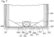
- the drain hole 330 includes a left drain hole portion 331, a rear drain hole portion 332 (illustrated nearer in the figure) and a right drain hole portion 333 in the inner-cover bottom wall 322 of the inner cover 320 and further that a tapered part 340 serving as a guide part for guiding the water toward the drain hole 330 includes a left tapered portion 341, a front tapered portion 342 (illustrated farther in the figure) and a right tapered portion 343.
- the tapered portions 341, 342, 343 are inclined so as to drain water toward the drain hole portions 331, 332, 333. Thus, they can also directly drain, in addition to evaporated water vapor, water accumulating in an area around and somewhat away from the drain hole 330.
- the inner cover 320 has a predetermined dimension so as to define small gaps ⁇ dl, ⁇ dr, etc., between the inner cover and the outer cover 310, the small gaps being smaller than the dimension of a specific intruding object (for example, 0.2 mm or smaller in order to prevent entry of specific intruding objects), and thus is received inside the outer cover 310.
- a predetermined gap ⁇ db smaller than the dimension of a specific intruding object is defined between the outer-cover bottom wall 312 of the outer cover 310 and the inner-cover bottom wall 322 of the inner cover 320.
- the predetermined gap between the respective bottom walls of the inner cover and the outer cover is specifically defined separate from the predetermined dimension, the predetermined gap may be regarded as being included in the predetermined dimension.
- the small gaps and the predetermined gap may have the same size or different sizes.
- Fig. 5 shows an exploded view of the sensing device DD dissembled in the front-to-rear direction and generally illustrates, from the rear to the front, the base unit 100, the functional unit 200, and the inner cover 320 and the outer cover 310 of the cover unit 300 in an exploded manner.
- the functional unit 200 includes a rotary unit R which can be turned to the left and right on the front face of the functional unit and a power supply circuit B such as a battery box and a stepdown circuit on the rear face of the functional unit.
- a power supply circuit B such as a battery box and a stepdown circuit on the rear face of the functional unit.
- On the front face of the rotary unit R are arranged the sensing element D1, the camera 220 of the imaging unit, the LED 240 which provides supplementary illuminating light, and the sensing element D2 in this order from the top to the bottom.
- the processing circuit 260 which processes signals from the sensing elements D1, D2 in response to sensing of to-be-sensed rays from an object through the optical members L1, L2 and signals from the camera 220, and the control circuit (not illustrated) which controls the camera 220 and the LED240, and the like.
- Packing 280 which is a watertight member is arranged between the inner cover 320 and the peripheral part of the rear face of the functional unit 200 at which the functional unit is fitted to the cover unit 300 (more specifically, the inner cover 320).
- the bottom wall 322 of the inner cover 320 including the inclined tapered part 340 has a shape different from that of the substantially flat bottom wall 312 of the outer cover 310.
- the optical members L1, L2 and the watertight packing 351, 352 are shown between the inner cover 320 and the outer cover 310.
- the optical member L1 is received in an opening part 337 of the inner cover 320 for the sensing element D1, with the packing 351 placed therebetween, and is pressed against the inner cover 320 by the outer cover 310.
- the optical member L2 is received in an opening part 338 of the inner cover 320 for the sensing element D2, with the packing 352 placed therebetween, and is pressed against the inner cover 320 by the outer cover 310.
- the inner cover 320 can achieve watertight fitting by the above-described packing 351, 352, the watertight packing 280 and the like and thus has a water ingress prevention structure for preventing water ingress from the outside of the inner cover 320 between the functional unit 200 and the optical members L1, L2.
- the camera window W1 and the lighting window W2 are incorporated in the inner cover 320 and are located in corresponding positions to the camera 220 and the illuminating LED 240, respectively, of the functional unit 200.
- Fig. 6 shows the front face of the inner cover 320 as viewed from diagonally below.
- the inner cover 320 is attached with the optical members L1, L2 and the LED window W2 and includes the camera window W1 in an incorporated manner.
- the shape of the tapered part 340 (tapered portions 341, 342, 343) located inside is seen as the external shape of the inner cover 320.
- the bottom wall 322 includes the drain hole portions 331, 332, 333 which penetrate from the inside to the outside.
- the bottom wall 322 also includes the inner-cover protrusion 324.
- temperature change is most likely to occur in the optical system (optical members) which directly face the outside and is designed to be thin or in the LED window which transmits near-infrared rays and/or far-infrared rays.
- optical system optical members
- These parts are often fitted to the cover in some way. Condensation tends to occur in these locations, and condensation water runs along the inner surface to the bottom surface inside the cover. Therefore, if that water can be quickly discharged to the outside, problems caused by internal condensation can be avoided.
- the sensing device DD for outdoor use can quickly and directly discharge condensation water to the outside and can also quickly and directly discharge a liquid such as raindrops to the outside in the case of ingress of the raindrops from outside of the device.
- the outer cover 310 is loosely fitted to the inner cover 320 having a predetermined dimension so as to define the small gaps ⁇ dl, ⁇ dr as described above.
- the predetermined gap ⁇ db smaller than the dimension of a specific intruding object is defined between the outer-cover bottom wall 312 of the outer cover 310 and the inner-cover bottom wall 322 of the inner cover 320. This makes it possible to quickly drain condensation water and the like to the outside and prevent ingress of specific intruding objects.
- the cover gap 315 including the small cover gap portions 316 to 319, typically having the predetermined gap ⁇ db is defined between the inner-cover protrusion 324 and the rectangular hole 313 ( Fig. 5 ) of the outer-cover bottom wall 312, and the water is drained through these gap portions to the outside of the sensing device DD.
- the sensing device DD is structured such that the outer cover 310 covers and conceals the drain hole 330 (drain hole portions 331, 332, 333) of the inner cover 320 from outside, so that the drain hole 330 of the inner cover 320 cannot be directly seen by an outsider, enhancing reliability of the sensing device which is a crime prevention device or the like.
- the bottom wall 312 of the outer cover 31 defines the predetermined gap ⁇ db with respect to the bottom wall 322 of the inner cover 320, and the inner cover has a predetermined dimension so as to define the small gaps ⁇ dl, ⁇ dr, etc.
- This can reduce the manufacturing cost and labor considering that, for example, a mold for forming slits having a width of 0.3 to 0.5 mm is difficult to produce, and manufacturing by resin molding is difficult because resin molding tends to produce defects such as burr formation due to the slit parts having a small width dimension.
- the double structure cover unit 300 including the inner cover 320 and the outer cover 310 although the shape of the inner-cover bottom wall 322 is affected by the shape of the tapered part 340 for water drainage formed on the bottom wall 322 of the inner cover 320, the shape of the bottom wall 312 of the outer cover is not affected by the shape of the tapered part, so that freedom in design can be enhanced as compared with the case of a single structure cover.
- the protection structure must be reevaluated or reviewed because the outer cover functions as the protection structure.
- the inner cover functions as the protection structure, so that the design of the outer cover can be changed without considering the protection structure. This can eliminate the necessity for reevaluating the protection structure.
- the above configuration of the present embodiment also provides the following secondary effects.
- the double structure cover unit 300 includes the inner cover 320, and the optical member L1 is attached to the inner cover 320 with the packing 351 placed therebetween (that is, waterproofing is provided at an internal part of the optical member L1).
- a jet of a liquid does not directly strike the packing 351. That is, the force of the jet reaching the packing 351 is weakened thanks to the structure.
- the jet from outside passes through the gap between the outer cover 310 and the lens, then flows along the surface of the outer lens 310, bypasses the end face of the outer lens 310 to the opposite face, and then reaches the watertight interface between the lens and the inner cover 320.
- the jet does not directly strike the packing 351.
- the flow path in the present embodiment is more complicated than in the conventional device, so that the force of the jet to pass through the packing can be made weaker, reducing the possibility of water ingress.
Landscapes
- Physics & Mathematics (AREA)
- General Physics & Mathematics (AREA)
- Engineering & Computer Science (AREA)
- Microelectronics & Electronic Packaging (AREA)
- Casings For Electric Apparatus (AREA)
- Burglar Alarm Systems (AREA)
- Investigating Or Analysing Materials By Optical Means (AREA)
- Other Air-Conditioning Systems (AREA)
Applications Claiming Priority (2)
| Application Number | Priority Date | Filing Date | Title |
|---|---|---|---|
| JP2020117793A JP7464979B2 (ja) | 2020-07-08 | 2020-07-08 | 屋外用検知装置 |
| PCT/JP2021/020816 WO2022009562A1 (ja) | 2020-07-08 | 2021-06-01 | 屋外用検知装置 |
Publications (4)
| Publication Number | Publication Date |
|---|---|
| EP4145966A1 true EP4145966A1 (de) | 2023-03-08 |
| EP4145966A4 EP4145966A4 (de) | 2023-10-11 |
| EP4145966B1 EP4145966B1 (de) | 2024-04-24 |
| EP4145966C0 EP4145966C0 (de) | 2024-04-24 |
Family
ID=79552338
Family Applications (1)
| Application Number | Title | Priority Date | Filing Date |
|---|---|---|---|
| EP21838403.0A Active EP4145966B1 (de) | 2020-07-08 | 2021-06-01 | Aussenerfassungsvorrichtung |
Country Status (7)
| Country | Link |
|---|---|
| EP (1) | EP4145966B1 (de) |
| JP (1) | JP7464979B2 (de) |
| BR (1) | BR112022024199A2 (de) |
| CL (1) | CL2022003352A1 (de) |
| ES (1) | ES2982049T3 (de) |
| PE (1) | PE20231756A1 (de) |
| WO (1) | WO2022009562A1 (de) |
Family Cites Families (6)
| Publication number | Priority date | Publication date | Assignee | Title |
|---|---|---|---|---|
| US5377076A (en) * | 1993-12-14 | 1994-12-27 | Wen; Hung-Sheng | Water proof structure for housing an outdoor sensor device |
| JP3285324B2 (ja) * | 1998-04-28 | 2002-05-27 | 矢崎総業株式会社 | 防水ケース |
| JP2005276656A (ja) * | 2004-03-25 | 2005-10-06 | Optex Co Ltd | タンパースイッチ構造及びそのタンパースイッチ構造を備えた防犯用センサ |
| JP4766670B2 (ja) | 2005-10-05 | 2011-09-07 | ホーチキ株式会社 | 防災防犯機器の防水構造 |
| JP6873708B2 (ja) | 2017-01-13 | 2021-05-19 | 新コスモス電機株式会社 | 通信機 |
| CN209357195U (zh) * | 2019-01-24 | 2019-09-06 | 北京富奥星电子技术有限公司 | 一种入侵探测器壳体 |
-
2020
- 2020-07-08 JP JP2020117793A patent/JP7464979B2/ja active Active
-
2021
- 2021-06-01 ES ES21838403T patent/ES2982049T3/es active Active
- 2021-06-01 WO PCT/JP2021/020816 patent/WO2022009562A1/ja not_active Ceased
- 2021-06-01 PE PE2022002789A patent/PE20231756A1/es unknown
- 2021-06-01 EP EP21838403.0A patent/EP4145966B1/de active Active
- 2021-06-01 BR BR112022024199A patent/BR112022024199A2/pt not_active Application Discontinuation
-
2022
- 2022-11-28 CL CL2022003352A patent/CL2022003352A1/es unknown
Also Published As
| Publication number | Publication date |
|---|---|
| ES2982049T3 (es) | 2024-10-14 |
| CL2022003352A1 (es) | 2023-05-12 |
| EP4145966B1 (de) | 2024-04-24 |
| PE20231756A1 (es) | 2023-11-06 |
| EP4145966A4 (de) | 2023-10-11 |
| BR112022024199A2 (pt) | 2023-01-17 |
| JP7464979B2 (ja) | 2024-04-10 |
| EP4145966C0 (de) | 2024-04-24 |
| JP2022015131A (ja) | 2022-01-21 |
| WO2022009562A1 (ja) | 2022-01-13 |
Similar Documents
| Publication | Publication Date | Title |
|---|---|---|
| US8249444B2 (en) | Covert camera with a fixed lens | |
| US20060162254A1 (en) | Sensor device for automatic door assembly | |
| US7782618B2 (en) | Electronic equipment | |
| JP2005276656A (ja) | タンパースイッチ構造及びそのタンパースイッチ構造を備えた防犯用センサ | |
| KR20130044371A (ko) | 차량용 카메라 장치 및 차량 내에 카메라 장치의 설치 방법 | |
| ATE284473T1 (de) | Türterminal mit not-auf-taster und anzeigemodul | |
| US6747275B2 (en) | Motion sensing system having short range capability | |
| EP4145966B1 (de) | Aussenerfassungsvorrichtung | |
| JP2003504671A (ja) | 環境覆い | |
| KR101692363B1 (ko) | 배전반 내부를 감시하기 위한 투시창 구조 | |
| JP4766670B2 (ja) | 防災防犯機器の防水構造 | |
| JP2000138469A (ja) | 呼吸孔の防水構造 | |
| KR200448216Y1 (ko) | 감시 카메라 및 이의 마이크 장착 구조 | |
| JP3747805B2 (ja) | 浴室内監視装置 | |
| KR20060098496A (ko) | 적외선 조명 감시 카메라 장치 | |
| KR101851185B1 (ko) | 해충에 의한 렌즈오염 방지 기술이 적용된 led 보안등 | |
| DK202200021U3 (da) | Et vindue eller en dør til installation i en bygning, og overvågningssystem omfattende en dør- eller vinduesføler | |
| KR200422158Y1 (ko) | 렌즈조절이 용이한 감시카메라 | |
| KR200423225Y1 (ko) | 방수형 cctv 외함장치 | |
| JPH0537357Y2 (de) | ||
| KR200421008Y1 (ko) | 적외선 감시카메라 | |
| EP3467444B1 (de) | Wasserdichtigkeit von sensoren | |
| KR200452657Y1 (ko) | Osd조절모듈이 케이블에 일체로 구비된 감시카메라 | |
| JP2022071093A (ja) | 火災感知器用遮蔽板の設置方法 | |
| US20090072127A1 (en) | Adjustable shroud for adjusting a detection field associated with a detector |
Legal Events
| Date | Code | Title | Description |
|---|---|---|---|
| STAA | Information on the status of an ep patent application or granted ep patent |
Free format text: STATUS: THE INTERNATIONAL PUBLICATION HAS BEEN MADE |
|
| PUAI | Public reference made under article 153(3) epc to a published international application that has entered the european phase |
Free format text: ORIGINAL CODE: 0009012 |
|
| STAA | Information on the status of an ep patent application or granted ep patent |
Free format text: STATUS: REQUEST FOR EXAMINATION WAS MADE |
|
| 17P | Request for examination filed |
Effective date: 20221129 |
|
| AK | Designated contracting states |
Kind code of ref document: A1 Designated state(s): AL AT BE BG CH CY CZ DE DK EE ES FI FR GB GR HR HU IE IS IT LI LT LU LV MC MK MT NL NO PL PT RO RS SE SI SK SM TR |
|
| REG | Reference to a national code |
Ref country code: DE Ref legal event code: R079 Ipc: G08B0013190000 Ref country code: DE Ref legal event code: R079 Ref document number: 602021012417 Country of ref document: DE Free format text: PREVIOUS MAIN CLASS: H05K0005020000 Ipc: G08B0013190000 |
|
| A4 | Supplementary search report drawn up and despatched |
Effective date: 20230908 |
|
| RIC1 | Information provided on ipc code assigned before grant |
Ipc: H05K 5/06 20060101ALI20230904BHEP Ipc: H05K 5/02 20060101ALI20230904BHEP Ipc: G08B 13/19 20060101AFI20230904BHEP |
|
| DAV | Request for validation of the european patent (deleted) | ||
| DAX | Request for extension of the european patent (deleted) | ||
| RIC1 | Information provided on ipc code assigned before grant |
Ipc: H05K 5/06 20060101ALI20231214BHEP Ipc: H05K 5/02 20060101ALI20231214BHEP Ipc: G08B 13/19 20060101AFI20231214BHEP |
|
| GRAP | Despatch of communication of intention to grant a patent |
Free format text: ORIGINAL CODE: EPIDOSNIGR1 |
|
| STAA | Information on the status of an ep patent application or granted ep patent |
Free format text: STATUS: GRANT OF PATENT IS INTENDED |
|
| INTG | Intention to grant announced |
Effective date: 20240119 |
|
| GRAS | Grant fee paid |
Free format text: ORIGINAL CODE: EPIDOSNIGR3 |
|
| GRAA | (expected) grant |
Free format text: ORIGINAL CODE: 0009210 |
|
| STAA | Information on the status of an ep patent application or granted ep patent |
Free format text: STATUS: THE PATENT HAS BEEN GRANTED |
|
| AK | Designated contracting states |
Kind code of ref document: B1 Designated state(s): AL AT BE BG CH CY CZ DE DK EE ES FI FR GB GR HR HU IE IS IT LI LT LU LV MC MK MT NL NO PL PT RO RS SE SI SK SM TR |
|
| REG | Reference to a national code |
Ref country code: GB Ref legal event code: FG4D |
|
| REG | Reference to a national code |
Ref country code: CH Ref legal event code: EP |
|
| REG | Reference to a national code |
Ref country code: DE Ref legal event code: R096 Ref document number: 602021012417 Country of ref document: DE |
|
| REG | Reference to a national code |
Ref country code: IE Ref legal event code: FG4D |
|
| U01 | Request for unitary effect filed |
Effective date: 20240515 |
|
| U07 | Unitary effect registered |
Designated state(s): AT BE BG DE DK EE FI FR IT LT LU LV MT NL PT SE SI Effective date: 20240527 |
|
| U20 | Renewal fee for the european patent with unitary effect paid |
Year of fee payment: 4 Effective date: 20240625 |
|
| PG25 | Lapsed in a contracting state [announced via postgrant information from national office to epo] |
Ref country code: IS Free format text: LAPSE BECAUSE OF FAILURE TO SUBMIT A TRANSLATION OF THE DESCRIPTION OR TO PAY THE FEE WITHIN THE PRESCRIBED TIME-LIMIT Effective date: 20240824 |
|
| PG25 | Lapsed in a contracting state [announced via postgrant information from national office to epo] |
Ref country code: HR Free format text: LAPSE BECAUSE OF FAILURE TO SUBMIT A TRANSLATION OF THE DESCRIPTION OR TO PAY THE FEE WITHIN THE PRESCRIBED TIME-LIMIT Effective date: 20240424 |
|
| PG25 | Lapsed in a contracting state [announced via postgrant information from national office to epo] |
Ref country code: GR Free format text: LAPSE BECAUSE OF FAILURE TO SUBMIT A TRANSLATION OF THE DESCRIPTION OR TO PAY THE FEE WITHIN THE PRESCRIBED TIME-LIMIT Effective date: 20240725 |
|
| REG | Reference to a national code |
Ref country code: ES Ref legal event code: FG2A Ref document number: 2982049 Country of ref document: ES Kind code of ref document: T3 Effective date: 20241014 |
|
| PG25 | Lapsed in a contracting state [announced via postgrant information from national office to epo] |
Ref country code: PL Free format text: LAPSE BECAUSE OF FAILURE TO SUBMIT A TRANSLATION OF THE DESCRIPTION OR TO PAY THE FEE WITHIN THE PRESCRIBED TIME-LIMIT Effective date: 20240424 |
|
| PG25 | Lapsed in a contracting state [announced via postgrant information from national office to epo] |
Ref country code: PL Free format text: LAPSE BECAUSE OF FAILURE TO SUBMIT A TRANSLATION OF THE DESCRIPTION OR TO PAY THE FEE WITHIN THE PRESCRIBED TIME-LIMIT Effective date: 20240424 Ref country code: NO Free format text: LAPSE BECAUSE OF FAILURE TO SUBMIT A TRANSLATION OF THE DESCRIPTION OR TO PAY THE FEE WITHIN THE PRESCRIBED TIME-LIMIT Effective date: 20240724 Ref country code: IS Free format text: LAPSE BECAUSE OF FAILURE TO SUBMIT A TRANSLATION OF THE DESCRIPTION OR TO PAY THE FEE WITHIN THE PRESCRIBED TIME-LIMIT Effective date: 20240824 Ref country code: HR Free format text: LAPSE BECAUSE OF FAILURE TO SUBMIT A TRANSLATION OF THE DESCRIPTION OR TO PAY THE FEE WITHIN THE PRESCRIBED TIME-LIMIT Effective date: 20240424 Ref country code: GR Free format text: LAPSE BECAUSE OF FAILURE TO SUBMIT A TRANSLATION OF THE DESCRIPTION OR TO PAY THE FEE WITHIN THE PRESCRIBED TIME-LIMIT Effective date: 20240725 Ref country code: RS Free format text: LAPSE BECAUSE OF FAILURE TO SUBMIT A TRANSLATION OF THE DESCRIPTION OR TO PAY THE FEE WITHIN THE PRESCRIBED TIME-LIMIT Effective date: 20240724 |
|
| PG25 | Lapsed in a contracting state [announced via postgrant information from national office to epo] |
Ref country code: CZ Free format text: LAPSE BECAUSE OF FAILURE TO SUBMIT A TRANSLATION OF THE DESCRIPTION OR TO PAY THE FEE WITHIN THE PRESCRIBED TIME-LIMIT Effective date: 20240424 |
|
| PG25 | Lapsed in a contracting state [announced via postgrant information from national office to epo] |
Ref country code: RO Free format text: LAPSE BECAUSE OF FAILURE TO SUBMIT A TRANSLATION OF THE DESCRIPTION OR TO PAY THE FEE WITHIN THE PRESCRIBED TIME-LIMIT Effective date: 20240424 Ref country code: SK Free format text: LAPSE BECAUSE OF FAILURE TO SUBMIT A TRANSLATION OF THE DESCRIPTION OR TO PAY THE FEE WITHIN THE PRESCRIBED TIME-LIMIT Effective date: 20240424 |
|
| REG | Reference to a national code |
Ref country code: DE Ref legal event code: R097 Ref document number: 602021012417 Country of ref document: DE |
|
| PG25 | Lapsed in a contracting state [announced via postgrant information from national office to epo] |
Ref country code: SM Free format text: LAPSE BECAUSE OF FAILURE TO SUBMIT A TRANSLATION OF THE DESCRIPTION OR TO PAY THE FEE WITHIN THE PRESCRIBED TIME-LIMIT Effective date: 20240424 |
|
| PG25 | Lapsed in a contracting state [announced via postgrant information from national office to epo] |
Ref country code: SM Free format text: LAPSE BECAUSE OF FAILURE TO SUBMIT A TRANSLATION OF THE DESCRIPTION OR TO PAY THE FEE WITHIN THE PRESCRIBED TIME-LIMIT Effective date: 20240424 Ref country code: SK Free format text: LAPSE BECAUSE OF FAILURE TO SUBMIT A TRANSLATION OF THE DESCRIPTION OR TO PAY THE FEE WITHIN THE PRESCRIBED TIME-LIMIT Effective date: 20240424 Ref country code: RO Free format text: LAPSE BECAUSE OF FAILURE TO SUBMIT A TRANSLATION OF THE DESCRIPTION OR TO PAY THE FEE WITHIN THE PRESCRIBED TIME-LIMIT Effective date: 20240424 Ref country code: CZ Free format text: LAPSE BECAUSE OF FAILURE TO SUBMIT A TRANSLATION OF THE DESCRIPTION OR TO PAY THE FEE WITHIN THE PRESCRIBED TIME-LIMIT Effective date: 20240424 Ref country code: MC Free format text: LAPSE BECAUSE OF FAILURE TO SUBMIT A TRANSLATION OF THE DESCRIPTION OR TO PAY THE FEE WITHIN THE PRESCRIBED TIME-LIMIT Effective date: 20240424 |
|
| REG | Reference to a national code |
Ref country code: CH Ref legal event code: PL |
|
| PLBE | No opposition filed within time limit |
Free format text: ORIGINAL CODE: 0009261 |
|
| STAA | Information on the status of an ep patent application or granted ep patent |
Free format text: STATUS: NO OPPOSITION FILED WITHIN TIME LIMIT |
|
| 26N | No opposition filed |
Effective date: 20250127 |
|
| PG25 | Lapsed in a contracting state [announced via postgrant information from national office to epo] |
Ref country code: IE Free format text: LAPSE BECAUSE OF NON-PAYMENT OF DUE FEES Effective date: 20240601 |
|
| PG25 | Lapsed in a contracting state [announced via postgrant information from national office to epo] |
Ref country code: CH Free format text: LAPSE BECAUSE OF NON-PAYMENT OF DUE FEES Effective date: 20240630 |
|
| U20 | Renewal fee for the european patent with unitary effect paid |
Year of fee payment: 5 Effective date: 20250627 |
|
| PG25 | Lapsed in a contracting state [announced via postgrant information from national office to epo] |
Ref country code: CY Free format text: LAPSE BECAUSE OF FAILURE TO SUBMIT A TRANSLATION OF THE DESCRIPTION OR TO PAY THE FEE WITHIN THE PRESCRIBED TIME-LIMIT; INVALID AB INITIO Effective date: 20210601 |
|
| PGFP | Annual fee paid to national office [announced via postgrant information from national office to epo] |
Ref country code: ES Payment date: 20250731 Year of fee payment: 5 |
|
| GBPC | Gb: european patent ceased through non-payment of renewal fee |
Effective date: 20250601 |
|
| PG25 | Lapsed in a contracting state [announced via postgrant information from national office to epo] |
Ref country code: HU Free format text: LAPSE BECAUSE OF FAILURE TO SUBMIT A TRANSLATION OF THE DESCRIPTION OR TO PAY THE FEE WITHIN THE PRESCRIBED TIME-LIMIT; INVALID AB INITIO Effective date: 20210601 |
|
| PG25 | Lapsed in a contracting state [announced via postgrant information from national office to epo] |
Ref country code: GB Free format text: LAPSE BECAUSE OF NON-PAYMENT OF DUE FEES Effective date: 20250601 |