EP4145988B1 - Autonomes fahrzeug, fütterungssystem und verfahren zum füttern von tieren - Google Patents
Autonomes fahrzeug, fütterungssystem und verfahren zum füttern von tieren Download PDFInfo
- Publication number
- EP4145988B1 EP4145988B1 EP21723932.6A EP21723932A EP4145988B1 EP 4145988 B1 EP4145988 B1 EP 4145988B1 EP 21723932 A EP21723932 A EP 21723932A EP 4145988 B1 EP4145988 B1 EP 4145988B1
- Authority
- EP
- European Patent Office
- Prior art keywords
- phase motor
- auger
- frequency controller
- animal feed
- control system
- Prior art date
- Legal status (The legal status is an assumption and is not a legal conclusion. Google has not performed a legal analysis and makes no representation as to the accuracy of the status listed.)
- Active
Links
Images

Classifications
-
- A—HUMAN NECESSITIES
- A01—AGRICULTURE; FORESTRY; ANIMAL HUSBANDRY; HUNTING; TRAPPING; FISHING
- A01K—ANIMAL HUSBANDRY; AVICULTURE; APICULTURE; PISCICULTURE; FISHING; REARING OR BREEDING ANIMALS, NOT OTHERWISE PROVIDED FOR; NEW BREEDS OF ANIMALS
- A01K5/00—Feeding devices for stock or game ; Feeding wagons; Feeding stacks
- A01K5/001—Fodder distributors with mixer or shredder
-
- A—HUMAN NECESSITIES
- A01—AGRICULTURE; FORESTRY; ANIMAL HUSBANDRY; HUNTING; TRAPPING; FISHING
- A01K—ANIMAL HUSBANDRY; AVICULTURE; APICULTURE; PISCICULTURE; FISHING; REARING OR BREEDING ANIMALS, NOT OTHERWISE PROVIDED FOR; NEW BREEDS OF ANIMALS
- A01K1/00—Housing animals; Equipment therefor
- A01K1/10—Feed racks
- A01K1/105—Movable feed barriers
-
- A—HUMAN NECESSITIES
- A01—AGRICULTURE; FORESTRY; ANIMAL HUSBANDRY; HUNTING; TRAPPING; FISHING
- A01K—ANIMAL HUSBANDRY; AVICULTURE; APICULTURE; PISCICULTURE; FISHING; REARING OR BREEDING ANIMALS, NOT OTHERWISE PROVIDED FOR; NEW BREEDS OF ANIMALS
- A01K5/00—Feeding devices for stock or game ; Feeding wagons; Feeding stacks
- A01K5/001—Fodder distributors with mixer or shredder
- A01K5/004—Fodder distributors with mixer or shredder with mixing or shredding element rotating on vertical axis
-
- A—HUMAN NECESSITIES
- A01—AGRICULTURE; FORESTRY; ANIMAL HUSBANDRY; HUNTING; TRAPPING; FISHING
- A01K—ANIMAL HUSBANDRY; AVICULTURE; APICULTURE; PISCICULTURE; FISHING; REARING OR BREEDING ANIMALS, NOT OTHERWISE PROVIDED FOR; NEW BREEDS OF ANIMALS
- A01K5/00—Feeding devices for stock or game ; Feeding wagons; Feeding stacks
- A01K5/02—Automatic devices
- A01K5/0266—Automatic devices with stable trolleys, e.g. suspended
-
- B—PERFORMING OPERATIONS; TRANSPORTING
- B01—PHYSICAL OR CHEMICAL PROCESSES OR APPARATUS IN GENERAL
- B01F—MIXING, e.g. DISSOLVING, EMULSIFYING OR DISPERSING
- B01F27/00—Mixers with rotary stirring devices in fixed receptacles; Kneaders
- B01F27/80—Mixers with rotary stirring devices in fixed receptacles; Kneaders with stirrers rotating about a substantially vertical axis
- B01F27/808—Mixers with rotary stirring devices in fixed receptacles; Kneaders with stirrers rotating about a substantially vertical axis with stirrers driven from the bottom of the receptacle
-
- B—PERFORMING OPERATIONS; TRANSPORTING
- B01—PHYSICAL OR CHEMICAL PROCESSES OR APPARATUS IN GENERAL
- B01F—MIXING, e.g. DISSOLVING, EMULSIFYING OR DISPERSING
- B01F27/00—Mixers with rotary stirring devices in fixed receptacles; Kneaders
- B01F27/80—Mixers with rotary stirring devices in fixed receptacles; Kneaders with stirrers rotating about a substantially vertical axis
- B01F27/92—Mixers with rotary stirring devices in fixed receptacles; Kneaders with stirrers rotating about a substantially vertical axis with helices or screws
- B01F27/921—Mixers with rotary stirring devices in fixed receptacles; Kneaders with stirrers rotating about a substantially vertical axis with helices or screws with helices centrally mounted in the receptacle
-
- B—PERFORMING OPERATIONS; TRANSPORTING
- B01—PHYSICAL OR CHEMICAL PROCESSES OR APPARATUS IN GENERAL
- B01F—MIXING, e.g. DISSOLVING, EMULSIFYING OR DISPERSING
- B01F33/00—Other mixers; Mixing plants; Combinations of mixers
- B01F33/50—Movable or transportable mixing devices or plants
- B01F33/502—Vehicle-mounted mixing devices
- B01F33/5021—Vehicle-mounted mixing devices the vehicle being self-propelled, e.g. truck mounted, provided with a motor, driven by tracks
-
- B—PERFORMING OPERATIONS; TRANSPORTING
- B01—PHYSICAL OR CHEMICAL PROCESSES OR APPARATUS IN GENERAL
- B01F—MIXING, e.g. DISSOLVING, EMULSIFYING OR DISPERSING
- B01F35/00—Accessories for mixers; Auxiliary operations or auxiliary devices; Parts or details of general application
- B01F35/20—Measuring; Control or regulation
- B01F35/22—Control or regulation
- B01F35/221—Control or regulation of operational parameters, e.g. level of material in the mixer, temperature or pressure
- B01F35/2214—Speed during the operation
- B01F35/22142—Speed of the mixing device during the operation
-
- B—PERFORMING OPERATIONS; TRANSPORTING
- B01—PHYSICAL OR CHEMICAL PROCESSES OR APPARATUS IN GENERAL
- B01F—MIXING, e.g. DISSOLVING, EMULSIFYING OR DISPERSING
- B01F35/00—Accessories for mixers; Auxiliary operations or auxiliary devices; Parts or details of general application
- B01F35/30—Driving arrangements; Transmissions; Couplings; Brakes
- B01F35/32—Driving arrangements
- B01F35/32005—Type of drive
- B01F35/32025—Battery driven
-
- H—ELECTRICITY
- H02—GENERATION; CONVERSION OR DISTRIBUTION OF ELECTRIC POWER
- H02P—CONTROL OR REGULATION OF ELECTRIC MOTORS, ELECTRIC GENERATORS OR DYNAMO-ELECTRIC CONVERTERS; CONTROLLING TRANSFORMERS, REACTORS OR CHOKE COILS
- H02P25/00—Arrangements or methods for the control of AC motors characterised by the kind of AC motor or by structural details
- H02P25/16—Arrangements or methods for the control of AC motors characterised by the kind of AC motor or by structural details characterised by the circuit arrangement or by the kind of wiring
- H02P25/18—Arrangements or methods for the control of AC motors characterised by the kind of AC motor or by structural details characterised by the circuit arrangement or by the kind of wiring with arrangements for switching the windings, e.g. with mechanical switches or relays
- H02P25/184—Arrangements or methods for the control of AC motors characterised by the kind of AC motor or by structural details characterised by the circuit arrangement or by the kind of wiring with arrangements for switching the windings, e.g. with mechanical switches or relays wherein the motor speed is changed by switching from a delta to a star, e.g. wye, connection of its windings, or vice versa
Definitions
- the present invention relates to an autonomous vehicle for use in feeding animals, in particular cows, such as dairy cows or beef cows, wherein the vehicle comprises a frame, in particular an undercarriage, displacement means for moving the frame, a container arranged on the frame for holding animal feed, and with a dispensing opening for dispensing the held animal feed from the container, a rotatable auger arranged in the container for mixing and/or chopping the held animal feed, an auger drive for rotating the auger, with a three-phase motor, and with a frequency controller or variable-frequency drive (VFD) for controlling the three-phase motor, in particular for setting a motor speed of the three-phase motor, wherein the three-phase motor is connectable, in particular via the frequency controller, to a three-phase power supply network (400 V), a battery power supply for the three-phase motor, which is configured to be charged by means of the three-phase power supply network, a sensor, which is configured to determine a signal that is related to the amount of animal feed in the container,
- the Lely Vector ® system is thus known, with an autonomously driving mixing and feeding robot with a mixing auger in a container for holding a batch of animal feed, and feed dosing means for dispensing animal feed from the container.
- the known autonomous feeding device mostly works adequately, it is not always fully able to remove the leftover feed from the auger and/or from the container at the end of feeding, in particular when the animal feed is sticky. This is undesirable because the composition of the leftover feed that remains on the auger may be different from the composition of a subsequent batch of feed that is to be loaded into the container. The composition of this subsequent batch of feed is then less accurate.
- US 2019/021278 A1 discloses an autonomous vehicle according to the preamble of claim 1, and livestock feeding system with a feed preparation area containing at least one storage, a livestock stable which is connected via driving routes to the feed preparation area, and a robot which comprises a variable speed electric drive controllable by a frequency transformer and a battery.
- the present invention aims to improve the known device so that the autonomous vehicle is better able to remove the leftover feed without worsening, in particular even while improving, the other functionalities such as adequate mixing and/or chopping of the animal feed in the container.
- Another aim of the present invention is to provide an autonomous vehicle for mixing and dispensing animal feed that is flexibly employable with respect to the power supply.
- the invention achieves this aim with a vehicle according to Claim 1, in particular an autonomous vehicle for use in feeding animals, in particular cows, such as dairy cows or beef cows, wherein the vehicle comprises a frame, in particular an undercarriage, displacement means for moving the frame, a container arranged on the frame for holding animal feed, and with a dispensing opening for dispensing the held animal feed from the container, a rotatable auger arranged in the container for mixing and/or chopping the held animal feed, an auger drive for rotating the auger, with a three-phase motor, in particular a 230 V/400 V three-phase motor, and with a frequency controller or variable-frequency drive (VFD) for controlling the three-phase motor, in particular for setting a motor speed of the three-phase motor, wherein the three-phase motor is connectable, in particular via the frequency controller, to a three-phase power supply network (400 V), a battery power supply for the three-phase motor, which is configured to be charged by means of the three-phase power supply network
- This vehicle can be connected to a three-phase power supply network, and can therefore use (maximum) 400 V AC voltage as power supply.
- the three-phase motor has three coils.
- the 400 V AC voltage is converted into 560 V DC voltage for the frequency controller.
- the frequency controller subsequently converts this DC voltage into a variable three-phase voltage for the three-phase motor, which may be between 0 and 400 V.
- the frequency controller adjusts the voltage as required to the right voltage for the coils of the three-phase motor.
- the value of this voltage is dependent on the set frequency.
- the vehicle can thus operate at high power and torque, notably in order to be able to chop and/or mix feed, such as relatively long-stemmed silage.
- the 400 V three-phase power supply network is disconnected, and just the battery power supply of the vehicle remains available.
- This delivers 48 V DC voltage for example, which can be converted into a DC voltage of 325 V for the frequency controller.
- the frequency controller is configured to deliver a variable three-phase voltage of between 0 and 230 V to the three-phase motor. Normally, a motor would be connected in delta configuration with such an AC voltage. However, the three-phase motor is unable to deliver sufficient torque in delta configuration, because the maximum current is limited by the frequency controller, unless a larger frequency controller is chosen which requires more installation space than is desirable or available.
- the three-phase motor is located in a central, tubular motor housing, which is arranged in the container of the vehicle.
- control system according to the invention is configured to leave the three-phase motor in star configuration, so that, at a low speed, a higher torque can be delivered, in particular in order to start the auger up from standstill in a container filled with animal feed and to start distributing the animal feed. In this case the speed is lower, but still sufficient to be able to dispense the animal feed.
- the auger especially the bottommost flatter portion thereof, has to be cleared of leftover feed, and the speed of the auger has to be increased substantially, for example from about 20 to 25 rpm to about 50 rpm.
- these numbers depend on the dimensions, in particular the cross section, of the auger.
- the three-phase motor will now be connected in delta configuration.
- the motor can then rotate faster, fast enough to be able to generate the required speed of rotation.
- the delivered torque is lower, but it is still sufficient to rotate the auger in the near-empty container.
- the vehicle is well able to remove the remaining animal feed, without the other functionalities, such as adequate mixing and/or chopping of the animal feed in the container, being negatively affected, with only limited installation space being required for the three-phase motor and frequency controller for this.
- the known star/delta configuration intended for starting up large electric motors, is different.
- the aim is different: namely, it is that of preventing large inrush currents from standstill
- the control is completely different: namely, it comprises starting up from standstill in star configuration, and subsequently, once a timer has elapsed or upon reaching a certain speed, switching to delta configuration, and then speeding up further until reaching operating speed.
- this does not take place when speeding up in one and the same operation, but only when moving to another operating state, or functionality, namely that of cleaning by rotation instead of mixing/chopping/dosing.
- the control for switching from star to delta is therefore not based on a timer or a speed, but based on a signal that is related to the amount of animal feed in the container. Furthermore, in practice, it is in principle necessary, after mixing and dispensing the feed, to first stop the three-phase motor, to change the settings for the frequency controller and to have the two relay groups switch from star to delta, and then to start the three-phase motor back up from standstill. Because in this case the switching effect is in practice already effectively suppressed by the frequency controller which is present, a star/delta switch is not needed for that purpose. It is therefore clear that the aim of the present invention is different.
- a feed-mixing wagon is known from EP1721520 , in which the augers are driven by a drive shaft, which is driven by a combustion engine of a tractor via an automatic gearbox with a plurality of gears.
- a weighing sensor measures the weight of the feed in the container. The measured weight is compared with a threshold value for a higher gear. When the measured weight falls below this threshold value, the gearbox changes automatically to a higher gear.
- this feed-mixing wagon does not have an electric motor that is switched between star and delta. Instead of driving the output shaft of the motor faster in order to increase the auger speed, the transmission ratio of the automatic gearbox is changed. This amounts to an entirely different solution.
- the control system is configured, in the case when the three-phase motor is disconnected from the three-phase power supply network after mixing and/or chopping held animal feed, to temporarily switch off the three-phase motor, and the control system is further configured, at a later point in time with animal feed held in the container, to start the three-phase motor back up while the three-phase motor is/stays connected to the frequency controller in star configuration, in particular by means of the still correspondingly switched first and second relay group, in order to dispense held animal feed from the container via the dispensing opening, wherein the control system is further configured, in the case when subsequently, after dispensing the held animal feed, the control system gives the "empty" indicator on the basis of the signal received from the sensor, to switch the first and second relay group from star to delta so that the three-phase motor is connected to the frequency controller in delta configuration, in particular in order to increase the maximum motor speed with which the torque for rotating the auger can be delivered and/or to increase the auger speed.
- the relatively small three-phase motor has a relatively high torque and low speed when starting up the auger in the container filled with animal feed, i.e. with the three-phase motor still in star configuration, while after switching to delta configuration, the three-phase motor can reach sufficient rotational speed to remove leftover feed from the auger by centrifugal effect.
- the desired functionality is achieved with a relatively small and inexpensive three-phase motor and relatively compact frequency controller.
- control system is configured, in the case when the control system does not give the "empty" indicator on the basis of the signal received from the sensor, to switch the first and second relay group so that the three-phase motor is connected to the frequency controller in star configuration. If the three-phase motor were connected in delta configuration to operate on the 400 V three-phase power supply network, in which case the frequency controller adjusts the voltage on the coils down to a correct, usable voltage, in which case it is even possible to momentarily overload the motor, i.e.
- the 400 V three-phase power supply network is disconnected, and then just the battery power supply is available.
- This delivers 48 V DC voltage for example, and can deliver, after conversion/inversion, an AC voltage with variable frequency and a variable three-phase voltage from 0 V to at most 230 V.
- the control system is configured to leave the three-phase motor in star configuration in this case, so that a relatively high torque can be exerted on the auger in order to set the auger in motion from standstill in the container filled with animal feed.
- the three-phase motor is switched from star to delta, so that the three-phase motor can drive the auger to a sufficiently high speed to clean the auger by rotation.
- the auger drive is configured to rotate the auger by means of the three-phase motor which is connected to the frequency controller in star configuration when chopping and/or mixing at a maximum auger speed of RPM max , wherein the auger drive is configured to increase the maximum auger speed to at least 2RPM max when the three-phase motor is connected to the frequency controller in delta configuration.
- Such an increase in the auger speed is sufficient to practically completely remove the remaining amount of feed.
- the frame comprises an undercarriage with wheels, wherein the vehicle is provided with navigation means that are connected to the control system in order to autonomously drive the vehicle over a surface, such as a floor in an animal shed or yard of a farm.
- a vehicle such as the mixing and feeding robot of the Lely-Vector ® system, which then has to be modified according to the present invention, i.e. the power supply cable to the three-phase motor now comprises, according to the invention, six wires instead of three wires, which are connected to the first and second relay groups added for the invention via connection terminals, and the software of the control system is adapted to operate the relay groups according to the invention.
- the displacement means comprise a rail system, on which rail system the frame is arranged, and along which rail system the frame is movably arranged.
- the vehicle is then guided by the rail system.
- the frame with the container is, for example, suspended from a rail system or drivable on a rail system, to achieve the same advantages according to the invention.
- the navigation means are then limited to a measurement of the position along the rails or of the covered distance, for example.
- the senor comprises a weighing sensor, which is configured to determine a weight of animal feed held in the container.
- the signal from the weighing sensor forms the signal that is related to the amount of animal feed in the container.
- the control system is configured to determine a variable that is representative of the decrease in the weight of animal feed held in the container, in particular when dispensing same from the container, and to give the "empty" indicator in the case when the control system determines, on the basis of this variable, that this decrease in the weight is substantially no longer or hardly changing with time, i.e. for example has become equal to or fallen below a threshold value, for example as an amount of feed (kg) or a percentage (%), in particular over a predetermined period.
- a threshold value for example as an amount of feed (kg) or a percentage (%)
- the threshold value may be 0 or almost 0.
- the control system gives the "empty" indicator, although there may still be a remaining amount of feed in the container, for example because feed is stuck to the auger.
- the measured weight is tracked over time. Then, once the measured weight has stopped, or practically stopped, changing, the control system switches the three-phase motor from star to delta in order to allow the output shaft to rotate faster. This affords a significant advantage with respect to the comparison of the measured weight with a threshold value as known from document EP1721520 cited above. Suppose that the threshold value is 30 kg and the auger will rotate faster once the measured weight has fallen below this threshold value.
- the three-phase motor comprises an output shaft
- the auger drive comprises a transmission device with a fixed transmission ratio, in particular a gearbox, with an input shaft that is connected to the output shaft of the three-phase motor, and with an output shaft that is connected to the auger.
- the transmission device decreases the speed of the three-phase motor to the desired speed of the auger.
- the transmission ratio is constant, so that the gearbox is robust and durable.
- control system is configured to disconnect the battery power supply from the three-phase motor when the three-phase motor is connected, in particular via the frequency controller, to the three-phase power supply network. While the three-phase motor is connected to the three-phase power supply network in order to mix and/or chop the animal feed in the container and the battery power supply is being charged from the three-phase power supply network via one or more battery chargers, the battery power supply is disconnected from the three-phase motor by the control system.
- the control system controls the battery power supply so as to supply the three-phase motor with power only once the three-phase power supply network has been disconnected from the three-phase motor. This guarantees reliable operation.
- the invention also relates to a feeding system for automatically, in particular fully automatically, feeding animals, in particular cows, such as dairy cows or beef cows, with animal feed at at least one feeding place, wherein the feeding system comprises a vehicle as described above.
- the feeding system may then comprise a charging device, in particular a charging station, that is configured to be connected to a three-phase power supply network (400 V), wherein the vehicle is provided with a connecting device that is configured to be connected to the charging device in order to charge the battery power supply of the vehicle and in order to supply, in particular via the frequency controller, the three-phase motor with power when mixing and/or chopping held animal feed.
- a charging device in particular a charging station
- a connecting device that is configured to be connected to the charging device in order to charge the battery power supply of the vehicle and in order to supply, in particular via the frequency controller, the three-phase motor with power when mixing and/or chopping held animal feed.
- the feeding system prefferably be provided with a feeding fence, in particular in an animal shed space for holding animals, and a feeding alley that extends along the feeding fence, in particular on the side of the feeding fence opposite the animal shed space, and wherein the vehicle is configured to autonomously drive through the feeding alley and to dispense animal feed along the feeding fence.
- the invention also relates to a method for automatically feeding animals, in particular cows, such as dairy cows or beef cows, by means of a vehicle as described above. This method affords the same advantages as described above for the autonomous vehicle.
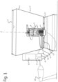
- the feeding system comprises a vehicle 1, which is provided with a frame or undercarriage 2 on which is arranged a container 3 with a filling opening 4 for animal feed with which it is to be filled.
- a container 3 Located within the container 3 is an auger 5 with a bottommost, flatter portion 6, which extends with only a small angle with respect to the horizontal.
- the auger 5 is rotatable about an axis of rotation A.
- Reference numeral 9 denotes an interior of a switch box, provided with a frequency controller or variable-frequency drive (VFD) 11.
- VFD variable-frequency drive
- Reference numeral 12 denotes a control system
- reference numeral 13 denotes a weighing sensor.
- the vehicle comprises a battery power supply 10.
- the battery power supply 10 is schematically illustrated in the switch box, the battery power supply 10 is in practice, for example, arranged on the undercarriage 2 beneath the container 3.
- the battery power supply 10 can be connected to a charging device 19, in this exemplary embodiment a charging station, by means of a connecting device 20.
- the charging device 19 is connected to a three-phase power supply network (400 V), i.e. when the vehicle 1 is connected to the charging device 19 by means of the connecting device 20, the battery power supply 10 is charged by means of battery chargers and 400 V from the three-phase power supply network is available.
- a three-phase power supply network 400 V
- the vehicle 1 is an autonomously driveable vehicle for feeding animals such as dairy cattle.
- the undercarriage 2 is provided with displacement means (not shown separately here), for example in the form of wheels or caterpillar tracks.
- the displacement means are driveable using one or more motors, thereby allowing the vehicle 1 to move.
- navigation means may be provided, which may be connected to the control system 12, for autonomous navigation.
- the container 3 is configured to be filled with animal feed via the filling opening 4. This happens from a feed kitchen or silo, for example.
- the animal feed may comprise, for example, silage, grass, hay, silage maize, etc.
- the animal feed needs to be chopped in many cases, and to be mixed in virtually all cases.
- the auger 5 is provided for that purpose, on which one or more blades (not shown in any more detail) are arranged if required.
- the flatter portion 6 of the auger 5 ensures that the food in the container 3 is picked up in an optimal manner, while guaranteeing that no, or at least little, feed remains between the auger 5 and the bottom of the container 3. However, the flatter nature of this portion 6 means that feed may remain on it.
- the container 3 further comprises means for dispensing the chopped and/or mixed animal feed, such as an openable and closable door or other opening, and optionally a discharge roller, discharge conveyor or the like.
- means for dispensing the chopped and/or mixed animal feed such as an openable and closable door or other opening, and optionally a discharge roller, discharge conveyor or the like.
- the weighing sensor 13 which is configured to determine the weight of the animal feed in the container 3, may in this case serve to determine whether the container 3 is practically “empty", for example because the measured weight is no longer decreasing.
- the control system 12 which is operationally connected to the weighing sensor 13 determines that the container 3 is "empty".
- the control system 12 then gives the "empty" indicator, i.e. a signal that is related to the "empty" state of the container 3.
- the weighing sensor 13 may also serve to weigh the animal feed on introduction into the container 3, so that the ration can be determined accurately.
- the auger 5 is driven using an auger drive, which comprises an auger motor 7 in the form of a three-phase motor, and a transmission device 8.
- the latter has, for example, a fixed transmission ratio of 80:1 or 75:1, and serves to make the auger 5 rotate about the axis of rotation A at a lower speed than the motor, and with a correspondingly higher torque, in order to be able to chop and/or mix.
- the three-phase motor 7 is an electric motor, in particular a 230 V/400 V three-phase motor, with three coils 14-1, 14-2 and 14-3, which are connectable to the frequency controller 11 by means of a first relay group 15 and a second relay group 16.
- first relay group 15 When the first relay group 15 is closed and the second relay group 16 is open, then the coils 14-1, 14-2, 14-3 of the motor 7 are in star configuration, and in the case when the first relay group 15 is open and the second relay group 16 is closed, then the coils 14-1, 14-2, 14-3 are in delta configuration.
- the nominal specifications of the motor 7 are 5.5 kW and 1500 rpm at 50 Hz and 230 V coil voltage.
- the frequency controller 11 is sized for 400 V and for 7.5 kW. Of course, other numbers are also possible in both cases.
- the motor 7 is running at 1500 rpm nominal, the auger rotates at 20 rpm nominal, for example. In principle, this is possible both in star and in delta configuration. The situation of the delta configuration and the connection to the three-phase power supply network (400 V) is now considered.
- the frequency controller could then adjust the voltage down (in principle) to 230 V nominal coil voltage, at 50 Hz, i.e. 1500 rpm. In the event of (heavy) loading, the frequency controller 11 may overload the motor 7 for a certain time. However, in many cases the torque will be insufficient for cutting through a large amount of silage loaded into the container, or to rotate the auger from standstill, because the frequency controller 11 is limited in current, and cannot then deliver the corresponding current.
- the motor 7 is connected in star configuration by actuating the first and second relay groups 15 and 16 in such a way that the first relay group 15 is closed and the second relay group 16 is open. A significantly higher torque is now generated for the same motor current. Therefore, the vehicle 1 is in principle operated with the motor 7 in star configuration.
- the control system determines, from the indication given by the weighing sensor 13 that the decrease in weight is no longer or hardly changing, the auger 5 in particular, and more particularly the bottommost flatter portion 6, still has to be cleaned, i.e. to be cleared of animal feed on and/or stuck to it.
- the auger 5 has to be rotated at a much higher speed, so that the remaining animal feed is removed by centrifugal effect.
- a speed of, or example, two to three times as high is found to be effective, which in the present case is thus about 50 rpm. Of course, this speed is dependent on the dimensions of the auger, and even on the type of animal feed.
- the frequency controller has to generate a correspondingly higher frequency. In this case approximately 120 Hz instead of 50 Hz nominal, for example.
- the corresponding speed of rotation of the motor which is then at close to 4000 rpm for example, and the resulting impedance properties of the coils, the coil voltage of the motor in star configuration is too low to still be able to deliver the torque required for rotation.
- the control system 12 then switches the first and second relay groups 15 and 16, so that the motor 7 is in delta configuration.
- the maximum coil voltage is now higher, namely 230 V instead of 132 V, and as a result the motor can deliver enough torque to rotate, and, with the set speed of rotation, to clean the auger 5 by rotation.
- a compact auger motor and frequency controller are thus provided which can deliver both a high torque (at low speed) for chopping and mixing, and a high speed (with low torque) for cleaning the auger.
- Both the motor and the frequency controller are suitable for operating on a 400 V three-phase power supply network and a battery power supply, which can be converted into a three-phase voltage between 0 and maximum 230 V.
Landscapes
- Life Sciences & Earth Sciences (AREA)
- Environmental Sciences (AREA)
- Chemical & Material Sciences (AREA)
- Chemical Kinetics & Catalysis (AREA)
- Animal Husbandry (AREA)
- Biodiversity & Conservation Biology (AREA)
- Birds (AREA)
- Zoology (AREA)
- Engineering & Computer Science (AREA)
- Power Engineering (AREA)
- Feeding And Watering For Cattle Raising And Animal Husbandry (AREA)
Claims (14)
- Autonomes Fahrzeug (1) zur Verwendung zum Füttern von Tieren, insbesondere Kühen, wie etwa Milchkühen oder Rindfleischkühen, wobei das Fahrzeug Folgendes umfasst:- einen Rahmen (2), insbesondere einen Unterwagen,- Verschiebemittel zum Bewegen des Rahmens (2),- einen Behälter (3), der zum Enthalten von Tierfutter am Rahmen angeordnet ist und zum Ausgeben des enthaltenen Tierfutters aus dem Behälter (3) eine Ausgabeöffnung umfasst,- eine drehbare Schnecke (5), die zum Mischen und/oder Hacken des enthaltenen Tierfutters im Behälter angeordnet ist,- einen Schneckenantrieb zum Drehen der Schnecke (5) mit einem Dreiphasenmotor (7) und mit einer Frequenzsteuerung (11) zum Steuern des Dreiphasenmotors (7), insbesondere zum Einstellen einer Motordrehzahl des Dreiphasenmotors (7), wobei der Dreiphasenmotor (7) mit einem Dreiphasenstromversorgungsnetzwerk (400 V), insbesondere via die Frequenzsteuerung (11), verbindbar ist,- eine Batteriestromversorgung (10) für den Dreiphasenmotor (7), die dazu ausgelegt ist, mittels des Dreiphasenstromversorgungsnetzwerks geladen zu werden,- einen Sensor (13), der dazu ausgelegt ist, ein Signal zu bestimmen, das die Menge von Tierfutter im Behälter (3) betrifft, und- ein Steuersystem (12) zum Steuern der Frequenzsteuerung (11), wobei das Steuersystem (12) mit dem Sensor (13) verbunden ist, um das Signal vom Sensor (13) zu empfangen,dadurch gekennzeichnet, dass der Dreiphasenmotor (7) via eine erste Relaisgruppe (15) mit der Frequenzsteuerung (11) verbunden ist, um in Sternauslegung verbindbar zu sein, und via eine zweite Relaisgruppe (16) mit der Frequenzsteuerung (11) verbunden ist, um in Dreieckauslegung verbindbar zu sein, und das Steuersystem (12) dazu ausgelegt ist, die erste und die zweite Relaisgruppe (15, 16) umzuschalten, derart, dass der Dreiphasenmotor (7) mit der Frequenzsteuerung (11) in Sternauslegung verbunden ist, wenn der Dreiphasenmotor (7) insbesondere via die Frequenzsteuerung (11) mit dem Dreiphasenstromversorgungsnetzwerk verbunden ist, um enthaltenes Tierfutter zu mischen und/oder zu hacken, und ferner dazu ausgelegt ist, in dem Fall, in dem der Dreiphasenmotor (7) von der Batteriestromversorgung (10) mit Strom versorgt wird, ohne mit dem Dreiphasenstromversorgungsnetzwerk verbunden zu sein, und das Steuersystem (12) eine "Leer"-Anzeige auf Basis des vom Sensor (13) empfangenen Signals ausgibt, die erste und die zweite Relaisgruppe (15, 16) umzuschalten, derart, dass der Dreiphasenmotor (7) in Dreieckauslegung mit der Frequenzsteuerung (11) verbunden ist, insbesondere um die maximale Motordrehzahl, mit der das Drehmoment zum Drehen der Schnecke geliefert werden kann, zu erhöhen.
- Fahrzeug nach Anspruch 1, wobei das Steuersystem (12) dazu ausgelegt ist, in dem Fall, in dem der Dreiphasenmotor (7) vom Dreiphasenstromversorgungsnetzwerk getrennt ist, nachdem enthaltenes Tierfutter gemischt und/oder gehackt wurde, den Dreiphasenmotor (7) vorübergehend auszuschalten, und das Steuersystem (12) ferner dazu ausgelegt ist, zu einem späteren Zeitpunkt, wenn sich Tierfutter im Behälter (3) befindet, das Dreiphasenmotor(7) wieder zu starten, während der Dreiphasenmotor (7) mit der Frequenzsteuerung (11) in Sternauslegung verbunden ist, um im Behälter (3) enthaltenes Tierfutter via die Ausgabeöffnung auszugeben, und wobei das Steuersystem (12) ferner dazu ausgelegt ist, in dem Fall, in dem nach Ausgeben des enthaltenen Tierfutters das Steuersystem (12) nachfolgend die "Leer"-Anzeige auf Basis des vom Sensor (13) empfangenen Signals gibt, die erste und die zweite Relaisgruppe (15, 16) von Stern in Dreieck umzuschalten, derart, dass der Dreiphasenmotor (7) mit der Frequenzsteuerung (11) in Dreieckauslegung verbunden ist, insbesondere um die maximale Motordrehzahl, mit der das Drehmoment zum Drehen der Schnecke geliefert werden kann, zu erhöhen.
- Fahrzeug nach Anspruch 1 oder 2, wobei in dem Fall, in dem das Steuersystem (12) die "Leer"-Anzeige auf Basis des vom Sensor (13) empfangenen Signals nicht gibt, das Steuersystem (12) dazu ausgelegt ist, die erste und die zweite Relaisgruppe (15, 16) umzuschalten, derart, dass der Dreiphasenmotor (7) in Sternauslegung mit der Frequenzsteuerung (11) verbunden ist.
- Fahrzeug nach einem oder mehreren der vorhergehenden Ansprüche, wobei der Schneckenantrieb dazu ausgelegt ist, die Schnecke (5) mittels des Dreiphasenmotors (7), der mit der Frequenzsteuerung (11) in Sternauslegung verbunden ist, zu drehen, wenn mit einer maximalen Schneckendrehzahl von RPMmax gehackt und/oder gemischt wird, und wobei der Schneckenantrieb dazu ausgelegt ist, die maximale Schneckendrehzahl auf mindestens 2 RPMmax zu erhöhen, wenn der Dreiphasenmotor (7) mit der Frequenzsteuerung (11) in Dreieckauslegung verbunden ist.
- Fahrzeug nach einem oder mehreren der vorhergehenden Ansprüche, wobei der Rahmen (2) mit einem Unterwagen mit Rädern versehen ist und wobei das Fahrzeug (1) mit Navigationsmitteln versehen ist, die mit dem Steuersystem (12) verbunden sind, um das Fahrzeug (1) autonom über eine Fläche zu fahren, wie etwa einen Boden in einem Tierstall oder einen Hof einer Farm.
- Fahrzeug nach einem oder mehreren der vorhergehenden Ansprüche, wobei die Verschiebemittel ein Schienensystem umfassen, wobei der Rahmen (2) auf dem Schienensystem angeordnet ist und wobei der Rahmen (2) entlang des Schienensystems bewegbar angeordnet ist.
- Fahrzeug nach einem oder mehreren der vorhergehenden Ansprüche, wobei der Sensor einen Wägesensor (13) umfasst, der dazu ausgelegt ist, ein Gewicht von im Behälter (3) enthaltenem Tierfutter zu bestimmen.
- Fahrzeug nach Anspruch 7, wobei das Steuersystem (12) dazu ausgelegt ist, eine Variable zu bestimmen, die für die Verringerung des Gewichts von im Behälter (3) enthaltenem Tierfutter repräsentativ ist, insbesondere beim Ausgeben desselben aus dem Behälter (3), und die "Leer"-Anzeige in dem Fall zu geben, in dem das Steuersystem (12) auf Basis der Variable bestimmt, dass sich die Verringerung des Gewichts über die Zeit im Wesentlichen nicht oder kaum ändert, insbesondere gleich einem Schwellwert geworden ist oder unter denselben abgefallen ist, insbesondere über eine vorbestimmte Periode.
- Fahrzeug nach einem oder mehreren der vorhergehenden Ansprüche, wobei der Dreiphasenmotor (7) eine Abtriebswelle umfasst und wobei der Schneckenantrieb eine Getriebevorrichtung (8) mit einem festen Übersetzungsverhältnis umfasst, mit einer Antriebswelle, die mit der Abtriebswelle des Dreiphasenmotors (7) verbunden ist, und mit einer Abtriebswelle, die mit der Schnecke (5) verbunden ist.
- Fahrzeug nach einem oder mehreren der vorhergehenden Ansprüche, wobei das Steuersystem (12) dazu ausgelegt ist, die Batteriestromversorgung (10) vom Dreiphasenmotor (7) zu trennen, wenn der Dreiphasenmotor (7), insbesondere via die Frequenzsteuerung (11), mit dem Dreiphasenstromversorgungsnetzwerk verbunden ist.
- Fütterungssystem zum automatischen Füttern von Tieren, insbesondere Kühen, wie etwa Milchkühen oder Rindfleischkühen, mit Tierfutter an mindestens einem Fütterungsort, wobei das Fütterungssystem ein autonomes Fahrzeug (1) nach einem oder mehreren der vorhergehenden Ansprüche umfasst.
- Fütterungssystem nach Anspruch 11, wobei das Fütterungssystem mit einer Ladevorrichtung (19) versehen ist, die dazu ausgelegt ist, mit einem Dreiphasenstromversorgungsnetzwerk (400 V) verbunden zu sein, wobei das Fahrzeug (1) mit einer Verbindungsvorrichtung (20) versehen ist, die dazu ausgelegt ist, mit der Ladevorrichtung (19) verbunden zu sein, um die Batteriestromversorgung (10) des Fahrzeugs (1) zu laden und um den Dreiphasenmotor (7), insbesondere via die Frequenzsteuerung (11), mit Strom zu versorgen, wenn enthaltenes Tierfutter gemischt und/oder gehackt wird.
- Fütterungssystem nach Anspruch 11 oder 12, wobei das Fütterungssystem mit einem Fütterungszaun, insbesondere in einen Tierstall zum Enthalten von Tieren, und einem Fütterungsgang, der sich entlang des Fütterungszauns erstreckt, insbesondere auf der Seite des Fütterungszauns gegenüber dem Tierstallraum, versehen ist und wobei das Fahrzeug (1) dazu ausgelegt ist, autonom durch den Fütterungsgang zu fahren und Tierfutter entlang des Fütterungszauns auszugeben.
- Verfahren zum automatischen Füttern von Tieren, insbesondere Kühen, wie etwa Milchkühen oder Rindfleischkühen, mittels eines Fahrzeugs (1) nach einem oder mehreren der Ansprüche 1 bis 10.
Applications Claiming Priority (2)
| Application Number | Priority Date | Filing Date | Title |
|---|---|---|---|
| NL2025498A NL2025498B1 (nl) | 2020-05-04 | 2020-05-04 | Autonoom voertuig, voersysteem, alsmede werkwijze voor het voeren van dieren |
| PCT/NL2021/050263 WO2021225434A1 (en) | 2020-05-04 | 2021-04-22 | Autonomous vehicle, feeding system, and method for feeding animals |
Publications (3)
| Publication Number | Publication Date |
|---|---|
| EP4145988A1 EP4145988A1 (de) | 2023-03-15 |
| EP4145988B1 true EP4145988B1 (de) | 2024-06-05 |
| EP4145988C0 EP4145988C0 (de) | 2024-06-05 |
Family
ID=70805189
Family Applications (1)
| Application Number | Title | Priority Date | Filing Date |
|---|---|---|---|
| EP21723932.6A Active EP4145988B1 (de) | 2020-05-04 | 2021-04-22 | Autonomes fahrzeug, fütterungssystem und verfahren zum füttern von tieren |
Country Status (4)
| Country | Link |
|---|---|
| EP (1) | EP4145988B1 (de) |
| CN (1) | CN115460913A (de) |
| NL (1) | NL2025498B1 (de) |
| WO (1) | WO2021225434A1 (de) |
Families Citing this family (3)
| Publication number | Priority date | Publication date | Assignee | Title |
|---|---|---|---|---|
| CN115024236A (zh) * | 2022-08-11 | 2022-09-09 | 山东胜伟牧业有限公司 | 规模化肉牛养殖自动化喂料设备 |
| CN115318147B (zh) * | 2022-08-29 | 2024-02-02 | 天津太平洋制药有限公司 | 一种药材混合装置 |
| CN116637548B (zh) * | 2023-07-27 | 2023-10-20 | 浙江汉信科技有限公司 | 一种电池浆料搅拌方法及搅拌装置 |
Family Cites Families (11)
| Publication number | Priority date | Publication date | Assignee | Title |
|---|---|---|---|---|
| JPH0666451A (ja) * | 1992-06-30 | 1994-03-08 | Nepon Kk | 温風暖房機の送風機制御方法 |
| DE102005021851A1 (de) | 2005-05-11 | 2006-11-16 | Trioliet Mullos B.V. | Futtermischer |
| NL1033349C2 (nl) * | 2007-02-06 | 2008-08-07 | Maasland Nv | Voerwagen voor het voeren van dieren zoals koeien. |
| WO2009070089A1 (en) * | 2007-11-29 | 2009-06-04 | Joensson Ragnar | Method and system for controlling an electric ac motor |
| CN101304225A (zh) * | 2008-06-04 | 2008-11-12 | 沈阳天成自动化工程有限公司 | 电动机节能转换控制器及控制方法 |
| US8657485B2 (en) * | 2010-07-12 | 2014-02-25 | Roto-Mix, Llc | Agricultural mixer with hydraulic drive system including jam detection and resolution features and method of using same |
| US10693408B2 (en) * | 2014-07-29 | 2020-06-23 | Dana Tm4 Inc. | Multiple phase electric machine, drive and control |
| CN204669266U (zh) * | 2015-05-15 | 2015-09-23 | 徐昌平 | 一种电动机驱动电路、电动机和离心机 |
| CN204891677U (zh) * | 2015-05-20 | 2015-12-23 | 江苏雷利电机股份有限公司 | 采用分体式直驱电机的搅拌机 |
| DE202016106837U1 (de) * | 2016-12-08 | 2018-03-09 | Trioliet B. V. | Futtermischwagen |
| DE202017104377U1 (de) * | 2017-07-21 | 2018-10-23 | Trioliet B. V. | Anlage zur Viehfütterung und Roboter |
-
2020
- 2020-05-04 NL NL2025498A patent/NL2025498B1/nl not_active IP Right Cessation
-
2021
- 2021-04-22 CN CN202180032011.6A patent/CN115460913A/zh active Pending
- 2021-04-22 EP EP21723932.6A patent/EP4145988B1/de active Active
- 2021-04-22 WO PCT/NL2021/050263 patent/WO2021225434A1/en not_active Ceased
Also Published As
| Publication number | Publication date |
|---|---|
| NL2025498B1 (nl) | 2021-11-18 |
| EP4145988A1 (de) | 2023-03-15 |
| EP4145988C0 (de) | 2024-06-05 |
| CN115460913A (zh) | 2022-12-09 |
| WO2021225434A1 (en) | 2021-11-11 |
Similar Documents
| Publication | Publication Date | Title |
|---|---|---|
| EP4145988B1 (de) | Autonomes fahrzeug, fütterungssystem und verfahren zum füttern von tieren | |
| US20100326363A1 (en) | Feed wagon for feeding animals such as cows | |
| EP3145300B1 (de) | Verfahren zum verteilen von futter über mehrere separater fütterungsorte und fütterungssystem dafür | |
| WO2015178763A1 (en) | A method for distributing feed over a plurality of separate feeding locations and a feeding system therefor | |
| NL2011148C2 (nl) | Voermengwagen. | |
| NL2011147C2 (nl) | Voermengwagen. | |
| US20230033258A1 (en) | Feeding system and method for feeding animals | |
| EP4075958B1 (de) | Fütterungssystem und verfahren zur fütterung von tieren | |
| EP2633768A1 (de) | Vorrichtung zum Mischen von Material und Verfahren zum Betreiben einer solchen Vorrichtung | |
| US20070113792A1 (en) | Feeding installation | |
| EP0721732B1 (de) | Aufbau für das Fördern von Tierfutter | |
| RU227844U1 (ru) | Робот-кормораздатчик | |
| EP3958667B1 (de) | Fütterungssystem und verfahren zum füttern von tieren und futtergreifer | |
| EP4601461A1 (de) | Fütterungssystem und verfahren zum füttern von tieren und kombiniertes stall zum halten von tieren und solch ein fütterungssystem | |
| WO2024134399A2 (en) | Feeding system and method for feeding animals, and, in combination, an animal shed for keeping animals and such a feeding system | |
| WO2025122020A1 (en) | Autonomous feed preparation vehicle and feed preparation system with the use of the autonomous feed preparation vehicle |
Legal Events
| Date | Code | Title | Description |
|---|---|---|---|
| STAA | Information on the status of an ep patent application or granted ep patent |
Free format text: STATUS: UNKNOWN |
|
| STAA | Information on the status of an ep patent application or granted ep patent |
Free format text: STATUS: THE INTERNATIONAL PUBLICATION HAS BEEN MADE |
|
| PUAI | Public reference made under article 153(3) epc to a published international application that has entered the european phase |
Free format text: ORIGINAL CODE: 0009012 |
|
| STAA | Information on the status of an ep patent application or granted ep patent |
Free format text: STATUS: REQUEST FOR EXAMINATION WAS MADE |
|
| 17P | Request for examination filed |
Effective date: 20221205 |
|
| AK | Designated contracting states |
Kind code of ref document: A1 Designated state(s): AL AT BE BG CH CY CZ DE DK EE ES FI FR GB GR HR HU IE IS IT LI LT LU LV MC MK MT NL NO PL PT RO RS SE SI SK SM TR |
|
| DAV | Request for validation of the european patent (deleted) | ||
| DAX | Request for extension of the european patent (deleted) | ||
| GRAP | Despatch of communication of intention to grant a patent |
Free format text: ORIGINAL CODE: EPIDOSNIGR1 |
|
| STAA | Information on the status of an ep patent application or granted ep patent |
Free format text: STATUS: GRANT OF PATENT IS INTENDED |
|
| RIC1 | Information provided on ipc code assigned before grant |
Ipc: H02P 25/18 20060101ALI20231109BHEP Ipc: A01K 5/02 20060101ALI20231109BHEP Ipc: A01K 5/00 20060101AFI20231109BHEP |
|
| RIC1 | Information provided on ipc code assigned before grant |
Ipc: A01K 5/00 20060101AFI20231205BHEP |
|
| INTG | Intention to grant announced |
Effective date: 20231218 |
|
| GRAS | Grant fee paid |
Free format text: ORIGINAL CODE: EPIDOSNIGR3 |
|
| GRAA | (expected) grant |
Free format text: ORIGINAL CODE: 0009210 |
|
| STAA | Information on the status of an ep patent application or granted ep patent |
Free format text: STATUS: THE PATENT HAS BEEN GRANTED |
|
| AK | Designated contracting states |
Kind code of ref document: B1 Designated state(s): AL AT BE BG CH CY CZ DE DK EE ES FI FR GB GR HR HU IE IS IT LI LT LU LV MC MK MT NL NO PL PT RO RS SE SI SK SM TR |
|
| REG | Reference to a national code |
Ref country code: CH Ref legal event code: EP |
|
| REG | Reference to a national code |
Ref country code: DE Ref legal event code: R096 Ref document number: 602021014107 Country of ref document: DE |
|
| REG | Reference to a national code |
Ref country code: IE Ref legal event code: FG4D |
|
| U01 | Request for unitary effect filed |
Effective date: 20240701 |
|
| U07 | Unitary effect registered |
Designated state(s): AT BE BG DE DK EE FI FR IT LT LU LV MT NL PT SE SI Effective date: 20240708 |
|
| PG25 | Lapsed in a contracting state [announced via postgrant information from national office to epo] |
Ref country code: HR Free format text: LAPSE BECAUSE OF FAILURE TO SUBMIT A TRANSLATION OF THE DESCRIPTION OR TO PAY THE FEE WITHIN THE PRESCRIBED TIME-LIMIT Effective date: 20240605 |
|
| PG25 | Lapsed in a contracting state [announced via postgrant information from national office to epo] |
Ref country code: GR Free format text: LAPSE BECAUSE OF FAILURE TO SUBMIT A TRANSLATION OF THE DESCRIPTION OR TO PAY THE FEE WITHIN THE PRESCRIBED TIME-LIMIT Effective date: 20240906 |
|
| PG25 | Lapsed in a contracting state [announced via postgrant information from national office to epo] |
Ref country code: ES Free format text: LAPSE BECAUSE OF FAILURE TO SUBMIT A TRANSLATION OF THE DESCRIPTION OR TO PAY THE FEE WITHIN THE PRESCRIBED TIME-LIMIT Effective date: 20240605 |
|
| PG25 | Lapsed in a contracting state [announced via postgrant information from national office to epo] |
Ref country code: NO Free format text: LAPSE BECAUSE OF FAILURE TO SUBMIT A TRANSLATION OF THE DESCRIPTION OR TO PAY THE FEE WITHIN THE PRESCRIBED TIME-LIMIT Effective date: 20240905 Ref country code: HR Free format text: LAPSE BECAUSE OF FAILURE TO SUBMIT A TRANSLATION OF THE DESCRIPTION OR TO PAY THE FEE WITHIN THE PRESCRIBED TIME-LIMIT Effective date: 20240605 Ref country code: GR Free format text: LAPSE BECAUSE OF FAILURE TO SUBMIT A TRANSLATION OF THE DESCRIPTION OR TO PAY THE FEE WITHIN THE PRESCRIBED TIME-LIMIT Effective date: 20240906 Ref country code: ES Free format text: LAPSE BECAUSE OF FAILURE TO SUBMIT A TRANSLATION OF THE DESCRIPTION OR TO PAY THE FEE WITHIN THE PRESCRIBED TIME-LIMIT Effective date: 20240605 Ref country code: RS Free format text: LAPSE BECAUSE OF FAILURE TO SUBMIT A TRANSLATION OF THE DESCRIPTION OR TO PAY THE FEE WITHIN THE PRESCRIBED TIME-LIMIT Effective date: 20240905 |
|
| PG25 | Lapsed in a contracting state [announced via postgrant information from national office to epo] |
Ref country code: PL Free format text: LAPSE BECAUSE OF FAILURE TO SUBMIT A TRANSLATION OF THE DESCRIPTION OR TO PAY THE FEE WITHIN THE PRESCRIBED TIME-LIMIT Effective date: 20240605 |
|
| PG25 | Lapsed in a contracting state [announced via postgrant information from national office to epo] |
Ref country code: IS Free format text: LAPSE BECAUSE OF FAILURE TO SUBMIT A TRANSLATION OF THE DESCRIPTION OR TO PAY THE FEE WITHIN THE PRESCRIBED TIME-LIMIT Effective date: 20241005 |
|
| PG25 | Lapsed in a contracting state [announced via postgrant information from national office to epo] |
Ref country code: CZ Free format text: LAPSE BECAUSE OF FAILURE TO SUBMIT A TRANSLATION OF THE DESCRIPTION OR TO PAY THE FEE WITHIN THE PRESCRIBED TIME-LIMIT Effective date: 20240605 |
|
| PG25 | Lapsed in a contracting state [announced via postgrant information from national office to epo] |
Ref country code: RO Free format text: LAPSE BECAUSE OF FAILURE TO SUBMIT A TRANSLATION OF THE DESCRIPTION OR TO PAY THE FEE WITHIN THE PRESCRIBED TIME-LIMIT Effective date: 20240605 Ref country code: SK Free format text: LAPSE BECAUSE OF FAILURE TO SUBMIT A TRANSLATION OF THE DESCRIPTION OR TO PAY THE FEE WITHIN THE PRESCRIBED TIME-LIMIT Effective date: 20240605 |
|
| PG25 | Lapsed in a contracting state [announced via postgrant information from national office to epo] |
Ref country code: SM Free format text: LAPSE BECAUSE OF FAILURE TO SUBMIT A TRANSLATION OF THE DESCRIPTION OR TO PAY THE FEE WITHIN THE PRESCRIBED TIME-LIMIT Effective date: 20240605 |
|
| PG25 | Lapsed in a contracting state [announced via postgrant information from national office to epo] |
Ref country code: SM Free format text: LAPSE BECAUSE OF FAILURE TO SUBMIT A TRANSLATION OF THE DESCRIPTION OR TO PAY THE FEE WITHIN THE PRESCRIBED TIME-LIMIT Effective date: 20240605 Ref country code: SK Free format text: LAPSE BECAUSE OF FAILURE TO SUBMIT A TRANSLATION OF THE DESCRIPTION OR TO PAY THE FEE WITHIN THE PRESCRIBED TIME-LIMIT Effective date: 20240605 Ref country code: RO Free format text: LAPSE BECAUSE OF FAILURE TO SUBMIT A TRANSLATION OF THE DESCRIPTION OR TO PAY THE FEE WITHIN THE PRESCRIBED TIME-LIMIT Effective date: 20240605 Ref country code: PL Free format text: LAPSE BECAUSE OF FAILURE TO SUBMIT A TRANSLATION OF THE DESCRIPTION OR TO PAY THE FEE WITHIN THE PRESCRIBED TIME-LIMIT Effective date: 20240605 Ref country code: IS Free format text: LAPSE BECAUSE OF FAILURE TO SUBMIT A TRANSLATION OF THE DESCRIPTION OR TO PAY THE FEE WITHIN THE PRESCRIBED TIME-LIMIT Effective date: 20241005 Ref country code: CZ Free format text: LAPSE BECAUSE OF FAILURE TO SUBMIT A TRANSLATION OF THE DESCRIPTION OR TO PAY THE FEE WITHIN THE PRESCRIBED TIME-LIMIT Effective date: 20240605 |
|
| PLBE | No opposition filed within time limit |
Free format text: ORIGINAL CODE: 0009261 |
|
| STAA | Information on the status of an ep patent application or granted ep patent |
Free format text: STATUS: NO OPPOSITION FILED WITHIN TIME LIMIT |
|
| 26N | No opposition filed |
Effective date: 20250306 |
|
| U20 | Renewal fee for the european patent with unitary effect paid |
Year of fee payment: 5 Effective date: 20250430 |
|
| PGFP | Annual fee paid to national office [announced via postgrant information from national office to epo] |
Ref country code: GB Payment date: 20250428 Year of fee payment: 5 |
|
| REG | Reference to a national code |
Ref country code: CH Ref legal event code: H13 Free format text: ST27 STATUS EVENT CODE: U-0-0-H10-H13 (AS PROVIDED BY THE NATIONAL OFFICE) Effective date: 20251125 |
|
| PG25 | Lapsed in a contracting state [announced via postgrant information from national office to epo] |
Ref country code: MC Free format text: LAPSE BECAUSE OF FAILURE TO SUBMIT A TRANSLATION OF THE DESCRIPTION OR TO PAY THE FEE WITHIN THE PRESCRIBED TIME-LIMIT Effective date: 20240605 |
|
| PG25 | Lapsed in a contracting state [announced via postgrant information from national office to epo] |
Ref country code: CH Free format text: LAPSE BECAUSE OF NON-PAYMENT OF DUE FEES Effective date: 20250430 |
|
| PG25 | Lapsed in a contracting state [announced via postgrant information from national office to epo] |
Ref country code: IE Free format text: LAPSE BECAUSE OF NON-PAYMENT OF DUE FEES Effective date: 20250422 |