EP4146135B1 - Fluidische gruppe und zugehörige vorrichtung zur arzneimittelherstellung - Google Patents
Fluidische gruppe und zugehörige vorrichtung zur arzneimittelherstellung Download PDFInfo
- Publication number
- EP4146135B1 EP4146135B1 EP21729931.2A EP21729931A EP4146135B1 EP 4146135 B1 EP4146135 B1 EP 4146135B1 EP 21729931 A EP21729931 A EP 21729931A EP 4146135 B1 EP4146135 B1 EP 4146135B1
- Authority
- EP
- European Patent Office
- Prior art keywords
- container
- fluidic
- valve
- chamber
- group
- Prior art date
- Legal status (The legal status is an assumption and is not a legal conclusion. Google has not performed a legal analysis and makes no representation as to the accuracy of the status listed.)
- Active
Links
Images

Classifications
-
- A—HUMAN NECESSITIES
- A61—MEDICAL OR VETERINARY SCIENCE; HYGIENE
- A61J—CONTAINERS SPECIALLY ADAPTED FOR MEDICAL OR PHARMACEUTICAL PURPOSES; DEVICES OR METHODS SPECIALLY ADAPTED FOR BRINGING PHARMACEUTICAL PRODUCTS INTO PARTICULAR PHYSICAL OR ADMINISTERING FORMS; DEVICES FOR ADMINISTERING FOOD OR MEDICINES ORALLY; BABY COMFORTERS; DEVICES FOR RECEIVING SPITTLE
- A61J1/00—Containers specially adapted for medical or pharmaceutical purposes
- A61J1/14—Details; Accessories therefor
- A61J1/20—Arrangements for transferring or mixing fluids, e.g. from vial to syringe
- A61J1/2003—Accessories used in combination with means for transfer or mixing of fluids, e.g. for activating fluid flow, separating fluids, filtering fluid or venting
- A61J1/2048—Connecting means
- A61J1/2055—Connecting means having gripping means
-
- A—HUMAN NECESSITIES
- A61—MEDICAL OR VETERINARY SCIENCE; HYGIENE
- A61J—CONTAINERS SPECIALLY ADAPTED FOR MEDICAL OR PHARMACEUTICAL PURPOSES; DEVICES OR METHODS SPECIALLY ADAPTED FOR BRINGING PHARMACEUTICAL PRODUCTS INTO PARTICULAR PHYSICAL OR ADMINISTERING FORMS; DEVICES FOR ADMINISTERING FOOD OR MEDICINES ORALLY; BABY COMFORTERS; DEVICES FOR RECEIVING SPITTLE
- A61J1/00—Containers specially adapted for medical or pharmaceutical purposes
- A61J1/14—Details; Accessories therefor
- A61J1/20—Arrangements for transferring or mixing fluids, e.g. from vial to syringe
- A61J1/2089—Containers or vials which are to be joined to each other in order to mix their contents
-
- A—HUMAN NECESSITIES
- A61—MEDICAL OR VETERINARY SCIENCE; HYGIENE
- A61J—CONTAINERS SPECIALLY ADAPTED FOR MEDICAL OR PHARMACEUTICAL PURPOSES; DEVICES OR METHODS SPECIALLY ADAPTED FOR BRINGING PHARMACEUTICAL PRODUCTS INTO PARTICULAR PHYSICAL OR ADMINISTERING FORMS; DEVICES FOR ADMINISTERING FOOD OR MEDICINES ORALLY; BABY COMFORTERS; DEVICES FOR RECEIVING SPITTLE
- A61J1/00—Containers specially adapted for medical or pharmaceutical purposes
- A61J1/14—Details; Accessories therefor
- A61J1/20—Arrangements for transferring or mixing fluids, e.g. from vial to syringe
- A61J1/2096—Combination of a vial and a syringe for transferring or mixing their contents
-
- A—HUMAN NECESSITIES
- A61—MEDICAL OR VETERINARY SCIENCE; HYGIENE
- A61M—DEVICES FOR INTRODUCING MEDIA INTO, OR ONTO, THE BODY; DEVICES FOR TRANSDUCING BODY MEDIA OR FOR TAKING MEDIA FROM THE BODY; DEVICES FOR PRODUCING OR ENDING SLEEP OR STUPOR
- A61M5/00—Devices for bringing media into the body in a subcutaneous, intra-vascular or intramuscular way; Accessories therefor, e.g. filling or cleaning devices, arm-rests
- A61M5/14—Infusion devices, e.g. infusing by gravity; Blood infusion; Accessories therefor
- A61M5/1414—Hanging-up devices
- A61M5/1415—Stands, brackets or the like for supporting infusion accessories
-
- A—HUMAN NECESSITIES
- A61—MEDICAL OR VETERINARY SCIENCE; HYGIENE
- A61M—DEVICES FOR INTRODUCING MEDIA INTO, OR ONTO, THE BODY; DEVICES FOR TRANSDUCING BODY MEDIA OR FOR TAKING MEDIA FROM THE BODY; DEVICES FOR PRODUCING OR ENDING SLEEP OR STUPOR
- A61M5/00—Devices for bringing media into the body in a subcutaneous, intra-vascular or intramuscular way; Accessories therefor, e.g. filling or cleaning devices, arm-rests
- A61M5/14—Infusion devices, e.g. infusing by gravity; Blood infusion; Accessories therefor
- A61M5/1414—Hanging-up devices
- A61M5/1417—Holders or handles for hanging up infusion containers
-
- A—HUMAN NECESSITIES
- A61—MEDICAL OR VETERINARY SCIENCE; HYGIENE
- A61M—DEVICES FOR INTRODUCING MEDIA INTO, OR ONTO, THE BODY; DEVICES FOR TRANSDUCING BODY MEDIA OR FOR TAKING MEDIA FROM THE BODY; DEVICES FOR PRODUCING OR ENDING SLEEP OR STUPOR
- A61M5/00—Devices for bringing media into the body in a subcutaneous, intra-vascular or intramuscular way; Accessories therefor, e.g. filling or cleaning devices, arm-rests
- A61M5/178—Syringes
- A61M5/1782—Devices aiding filling of syringes in situ
-
- A—HUMAN NECESSITIES
- A61—MEDICAL OR VETERINARY SCIENCE; HYGIENE
- A61M—DEVICES FOR INTRODUCING MEDIA INTO, OR ONTO, THE BODY; DEVICES FOR TRANSDUCING BODY MEDIA OR FOR TAKING MEDIA FROM THE BODY; DEVICES FOR PRODUCING OR ENDING SLEEP OR STUPOR
- A61M39/00—Tubes, tube connectors, tube couplings, valves, access sites or the like, specially adapted for medical use
- A61M39/22—Valves or arrangement of valves
- A61M39/24—Check- or non-return valves
- A61M2039/242—Check- or non-return valves designed to open when a predetermined pressure or flow rate has been reached, e.g. check valve actuated by fluid
-
- A—HUMAN NECESSITIES
- A61—MEDICAL OR VETERINARY SCIENCE; HYGIENE
- A61M—DEVICES FOR INTRODUCING MEDIA INTO, OR ONTO, THE BODY; DEVICES FOR TRANSDUCING BODY MEDIA OR FOR TAKING MEDIA FROM THE BODY; DEVICES FOR PRODUCING OR ENDING SLEEP OR STUPOR
- A61M2205/00—General characteristics of the apparatus
- A61M2205/50—General characteristics of the apparatus with microprocessors or computers
-
- A—HUMAN NECESSITIES
- A61—MEDICAL OR VETERINARY SCIENCE; HYGIENE
- A61M—DEVICES FOR INTRODUCING MEDIA INTO, OR ONTO, THE BODY; DEVICES FOR TRANSDUCING BODY MEDIA OR FOR TAKING MEDIA FROM THE BODY; DEVICES FOR PRODUCING OR ENDING SLEEP OR STUPOR
- A61M2209/00—Ancillary equipment
- A61M2209/08—Supports for equipment
- A61M2209/084—Supporting bases, stands for equipment
Definitions
- the present invention relates to a fluidic group and related apparatus for drug preparation.
- chemotherapy drugs used in cancer therapies can generate significant toxic effects, since they have a very narrow window of effective therapeutic concentration (or therapeutic range).
- the main critical elements include the following:
- Document US 2015/283322 A1 relates generally to medical fluid systems, and specifically to systems for providing IV fluid to patients.
- Document WO 2017/096072 A1 relates generally to medical fluid transfer systems, methods, and components: and specifically to electronically controlled medical fluid transfer systems, methods, and components.
- Document WO 2007/122209 A1 relates to the preparation and administration of a product and, more particularly, to the injection of the same into a living organism, for example, a human body.
- Document WO 2014/204894 A2 generally relates to devices and methods for administering the contents of vials and more specifically to a disposable one-time use apparatus and method that transfers and mixes the contents of one or more vials into a disposable injection device for administration into a subject such as a human being.
- Document WO 2015/071852 A2 relates in general to medical devices, in particular medical devices for the treatment and/or control of fluids, such as biological liquids and tissues in the fluid state.
- Aim of the present invention is to provide a fluidic group and related apparatus for drug preparation which solve the disadvantages of the known art.
- the figures are shown with reference to the triaxial Cartesian system XYZ defined by an X axis, a Y axis and a Z axis, orthogonal to each other.
- a gravity acceleration acting along the Z axis is considered.
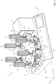
- Figures 1 , 1A and 1B show an apparatus for preparation of chemotherapy drugs (hereafter referred to as "apparatus” and indicated by reference number 1).
- the apparatus 1 includes a base 3 configured to be placed on a support (not shown, such as a table, a piece of furniture or a platform), and in particular on a surface (not shown) of the support extending in a horizontal XY plane defined by the axes X and Y.
- the base 3 has an upper surface 3a and a lower surface 3b opposite each other along the Z axis, and extending substantially parallel to each other and parallel to the XY plane.
- a first rotor 9 and a second rotor 11 are carried by the base 3 and have a substantially flat shape.
- the first and the second rotor 9, 11 have a main extension in the XY plane and have a substantially flat circular shape in the XY plane.
- the rotors 9, 11 are arranged superimposed one upon the other, are coaxial to each other and are coupled to the base 3 by means of a central stator 13 fixed to the upper surface 3a, extending perpendicularly to said surface 3a and arranged centrally to the rotors 9, 11.
- the stator 13 of rectilinear shape has main extension along a rotation axis 15 parallel to the Z axis and includes for example a rod.
- the stator 13 has a first lower end (not shown) and a second upper end 13b, opposite each other along the Z axis, and is fixed to the base 3 by the first lower end.
- the rotors 9, 11 are coupled to the stator 13 in a per se known manner, for example by means of respective bearings (not shown), and are configured to rotate with respect to the stator 13.
- the stator 13 is arranged centrally with respect to the rotors 9, 11 which rotate, in respective rotation planes (parallel to the XY plane), with respect to the rotation axis 15 (orthogonal to the rotation planes).
- the rotors 9, 11 are therefore placed at different levels along the Z axis, and in particular the first (lower) rotor 9 faces the upper surface 3a of the base 3 and is at a distance from said upper surface 3a, along the Z axis, a distance which is less than the distance shown by the second (upper) rotor 11.
- the first lower rotor 9 is interposed, along the Z axis, between the base 3 and the second upper rotor 11.
- the first rotor 9 includes a plurality of first seats 17 each configured to house a respective fluidic device 21, better described below.
- Each fluidic device 21 is coupled to a respective first fluidic container 22 (hereinafter, first container 22).
- each first container 22 - of known type - includes a first body 22a (e.g., bottle, vial, ampoule) defining a first internal volume and having a through opening closed by a first cap 22b (e.g., of silicone).
- Each first container 22 is adapted to contain a respective ingredient, and is releasably coupled (e.g., by interlocking) to the respective fluidic device 21 at the cap 22b, as better described below.
- the first containers 22 and the respective fluidic devices 21 are arranged, angularly equally spaced apart between them, at an outer edge of the first rotor 9.
- the second rotor 11 includes a plurality of second seats 19 configured to house a respective plurality of supports 23.
- each support 23 is releasably coupled to the respective second seat 19.
- Each support 23 includes a first surface 23a and a second surface 23b ( Figure 5A ) opposite to each other along the Z axis, and includes a respective second portion (extending at the second surface 23b) shaped so as to releasably fit into the respective second seat 19, for example by interlocking in order to fix the support 23 to the respective second seat 19.
- the second surfaces 23b of the supports 23 thus face the second rotor 11.
- Each support 23 is releasably coupled to a respective second fluid container 24 (hereinafter, second container 24) also of known type.
- each second container 24 includes a second body 24a (e.g., bottle, vial, ampoule) defining a second internal volume and having a through opening closed by a second cap 24b (e.g., of silicone).
- Each second container 24 is adapted to contain a respective chemotherapeutic drug to be administered to a respective patient.
- Each second container 24 is releasably coupled (e.g., by interlocking) to the respective support 23 at the cap 22b.
- each cap 22b faces the first surface 23a of the respective support 23.
- the second containers 24 and the respective supports 23 are arranged, angularly equally spaced apart between them, at an outer edge of the second rotor 11.
- the second rotor 11 has a larger diameter than the respective diameter of the first rotor 9.
- An operating device 5 is coupled (in particular, fixed) to the upper surface 3a of the base 3.
- the operating device 5 has a side wall 5a facing the rotors 9, 11.
- the operating device 5 comprises first operating means (not shown), of a type known per se and configured to allow rotation of the rotors 9, 11 with respect to the stator 13.
- the first operating means extend starting from the side wall 5a.
- Each rotor 9, 11 is independently operated such that the rotors 9, 11 can rotate independently of each other, with different speeds and/or with opposite angular directions (e.g., clockwise and counterclockwise in the top view of Figure 1B ) and with different angular speeds.
- the first operating means 27 comprise a first and a second motorised gear (not shown, such as gear wheels).
- the first motorised gear is configured to engage a first toothing fixed to the first rotor 9 (e.g., fixed to a perimeter surface of the first rotor 9); the second motorised gear is configured to engage a second toothing fixed to the second rotor 11 (e.g., fixed to a perimeter surface of the second rotor 11).
- the first operating means 27 comprise a first and second belt drive configured to cooperate frictionally with the first and, respectively, second rotor 9, 11 (e.g., with the side surfaces of the rotors 9, 11).
- the first operating means 27 exploit, in a per se known manner, electromagnetic fields to move the rotors 9, 11.
- the first operating means 27 are included in the base 3 and the stator 13 includes respective drive means to actuate the rotors 9, 11.
- the first operating means 27 are based on direct drive technologies.
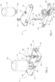
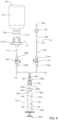
- Figures 2-4 show one of the fluidic devices 21 in detail.
- the fluidic device 21 includes a main body 59 shaped so as to releasably couple with (e.g., fit into) the respective first seat 17, for example by interlocking so as to releasably fix the fluidic device 21 to the respective first seat 17.
- the fluidic device 21 comprises a fluidic connection means 25 fixed to the main body 59 and adapted to fluidically connect the first container 22 with the second container 24.
- the fluidic connection means 25 includes a first hollow needle 60 (hereinafter, also referred to as first needle 60 and having a first and second end 60a, 60b) and a first tubular element 62 (e.g., of plastic material and having a first and second end 62a, 62b).
- the first needle 60 is configured to be coupled to (e.g., inserted into) the second cap 24b through the first end 60a, as better described below.
- the first tubular element 62 is flexible, is coupled to the main body 59 through the first end 62a and is coupled, through the second end 62b, to the second end 60b of the first needle 60.
- the first tubular element 62 and the first needle 60 are coupled to each other so as to allow a passage of fluid from the main body 59 through the first tubular element 62 and the first needle 60.
- the first tubular element 62 has a first through opening defined between the ends 62a, 62b
- the first needle 60 has a second through opening defined between the ends 60a, 60b.
- the first and second cavity face each other at the second ends 60b, 62b.
- the first needle 60 is supported, in a releasable manner, by a first support portion 152 of the main body 59, and is movable, as shown below, with respect to the main body 59.
- the first support portion 152 extends starting from, and perpendicularly to, a surface 59' of the main body 59, said surface 59' being facing the containers 22, 24 when the latter are coupled to the main body 59.
- the first support portion 152 supports the first needle 60 so that the second end 60b of the first needle 60 is facing the main body 59 (at the surface 59'), and so that the first end 60a of the first needle 60 is facing the first container 22.
- the fluidic device 21 and the support 23 considered are mutually arranged so that the first needle 60 is facing the second cap 24b along the Z axis.
- the main body 59 has a housing cavity 59a in which a syringe 154 comprising a hollow body 156 is housed (in detail, inclusive).
- the body 156 defines a cavity 158 having a polygonal (e.g. circular) cross-section.
- the body 156 includes an end 156a having a through opening 160.
- a plunger (or piston) 150 Internally to the cavity 158 there is a plunger (or piston) 150, movable (e.g., cooperating with sliding) with respect to the body 156 and operable so as to generate a pressure gradient (e.g., at the through opening 160).
- the piston 150 is movable, longitudinally to the body 156, in the cavity 158 and has a first and second end 150a, 150b opposite each other.
- the piston 150 comprises, at the first end 150a, a seal element 150' sliding in a fluid-tight manner in the body 156 (in detail, it slides along an internal surface of the body 156, facing said cavity) thus defining a first and a second chamber 162a, 162b having a variable volume in the cavity 158.
- the chambers 162a, 162b are fluid-tightly separated from each other by the seal element 150' and have respective volumes that are variable as a function the axial position assumed by the piston 150 with respect to the body 156.
- the first chamber 162a is in fluid communication with the outside of the syringe 154 via the through opening 160 located at the end 156a.
- the piston 150 is movable from a first position (of compression of the first chamber 162a) to a second position (of expansion of the first chamber 162a): in the first position, the seal element 150' is at the end 156a and the piston 150 is almost completely housed in the cavity 158, and therefore the first chamber 162a has a volume smaller than the volume of the second chamber 162b (in other words, the seal element 150' has a first distance D 1 from the end 156a of the body 156, and the first chamber 162a has a first volume); and in the second position, only the seal element 150' is in the cavity 158 and the piston 150 is almost completely outside the body 156, and therefore the first chamber 162a has a volume greater than the volume of the second chamber 162b (in other words, the seal element 150' has a second distance D 2 from the end 156a of the body 156, and the first chamber 162a has a second volume, the second distance D 2 being greater than the first distance D 1 and the second chamber being greater
- the syringe 154 is coupled to the first container 22 by means of a forking element 166 and a first one-way (non-return, or check) valve 168 (hereinafter, first valve 168), that are also arranged in the housing cavity 59a.
- the first valve 168 has a first and a second end 168a, 168b opposite to each other, and is operable in an opening state and, alternatively, in a closing state as a function of a first force caused by a first pressure difference between said ends 168a, 168b.
- the first pressure difference is a function of a first pressure gradient present at the first valve 168, which in turn is related to said pressure gradient in the through opening 160.
- the forking element 166 and the first valve 168 are in pneumatic communication with the through opening 160 of the syringe 154.
- the first valve 168 In a rest condition, the first valve 168 is in the closing state; when, on the other hand, the pressure gradient in the through opening 160 is directed towards the cavity 158 (i.e.
- the first valve 168 passes from the closing state to the opening state, allowing a passage of fluid only from the first container 22 towards the syringe 154 (thus preventing a passage of fluid from the syringe 154 towards the first container 22), and then returns to the closing state when the pressure gradient in the through opening 160 is exhausted.
- the forking element 166 allows the passage of fluid, coming from the syringe 154, along a first and a second fluidic path, as better described below.
- the forking element 166 has a first and second end 166a, 166b opposite each other. At the second end 166b, the forking element 166 has a first and second fluidic channel 166', 166'' and, at the first end 166a, the forking element 166 has a third fluidic channel 166'''.
- the fluidic channels 166', 166'', 166′′′ have a Y-arrangement between them (i.e. they are joined and fluidically connected to each other in a connection portion).
- the through opening 160 of the syringe 154 is coupled to (e.g., fixed to, and in fluid communication with) the first end 166a of the forking element 166 (in detail, to the third fluidic channel 166''').
- the syringe 154 and the forking element 166 are coupled to each other directly or through a further tubular element (not shown and analogous to the first tubular element 62) .
- first fluidic channel 166' of the second end 166b is coupled to (e.g., fixed to, and in fluid communication with) the second end 168b of the first valve 168 through a second tubular element 170 (analogous to the first tubular element 62).
- the first end 168a of the first valve 168 is coupled to (e.g., fixed to, and in fluid communication with) the first cap 22b.
- the first end 168a is coupled to (e.g., fixed to, and in fluid communication with; e.g., directly or through a third tubular element 172 analogous to the first tubular element 62) an interface means 171 that is releasably couplable to the first container 22.
- the interface means 171 is placed, at least partially, externally to the housing cavity 59a and includes a second support portion 171b.
- the second support portion 171b is fixed to the main body 59, is external to the housing cavity 59a and, when the first container 22 is coupled to the fluidic device 21, is releasably fixed to the second cap 22b so as to physically support and sustain the first container 22.
- the second support portion 171b includes a second hollow needle 171a (hereinafter, second needle 171, analogous to the first needle 60) configured to be coupled to (e.g., inserted into) the first cap 22b.
- second needle 171a analogous to the first needle 60
- the forking element 166, the second tubular element 170, the first valve 168, the interface means 171 and, if any, the third tubular element 172 define the first fluidic path, which therefore crosses the first and third fluidic channel 166', 166′′′ to fluidically connect the first internal volume and the first chamber 162a with each other.
- a second one-way (non-return, or check) valve 176 (hereinafter, second valve 176) is interposed between the fluidic connection means 25 and the forking element 166.
- the second valve 176 has a first and a second end 176a, 176b opposite each other, and is operable in an opening state and, alternatively, in a closing state as a function of a second force caused by a second pressure difference between said ends 176a, 176b.
- the second pressure difference is a function of a second pressure gradient present at the second valve 176, which in turn is related to said pressure gradient in the through opening 160.
- the forking element 166 and the second valve 176 are in pneumatic communication with the through opening 160 of the syringe 154.
- the second valve 176 In a rest condition, the second valve 176 is in the closing state; when, however, the pressure gradient in the through opening 160 is directed towards the forking element 166 (i.e., towards the outside of the syringe 154) and has an absolute value greater than a second threshold (e.g., equal to the first threshold; in other words, when the second force acting on the second valve 176 is greater than a further threshold force), the second valve 176 passes from the closing state to the opening state, allowing a passage of fluid only from the syringe 154 towards the first needle 60, and therefore towards the second container 24 (thus preventing a passage of fluid from the second container 24 towards the syringe 154), to then return to the closing state when the pressure gradient in the through opening 160 is exhausted.
- a second threshold e.g., equal to the first threshold; in other words, when the second force acting on the second valve 176 is greater than a further threshold force
- the second fluidic channel 166' ' of the second end 166b is coupled to (e.g., fixed to, and in fluid communication with) the second end 176b of the second valve 176 through a fourth tubular element 178 (analogous to the first tubular element 62).
- the first end 176a of the second valve 176 is coupled to (e.g., fixed to, and in fluid communication with) the first end 62a of the first tubular element 62.
- the second valve 176 and the fourth tubular element 178 are also included in the housing cavity 59a.
- the forking element 166, the fourth tubular element 178, the second valve 176 and the fluidic connection means 25 define the second fluidic path, which therefore crosses the second and the third fluidic channels 166'', 166′′′ to fluidically connect the first chamber 162a and the second internal volume with each other.
- the fluidic device 21 comprises the following elements, which are assembled together (e.g. by gluing) so as to form a single group adapted to transfer liquids without leakage:
- the operating device 5 further comprises second operating means 70, configured to move the first needle 60 by displacing it upwards (thus towards the rotor 11 along the Z axis) so as to couple the first needle 60 of the fluidic device 21 with the second cap 24b of the second container 24 considered.
- the second operating means 70 extend starting from the side wall 5a, and include a first translation means 72 and a first gripping means 74, operatively coupled to each other.
- the first gripping means 74 is configured to couple to the first needle 60, allowing for the aforesaid movement.
- the first gripping means 74 includes two arms 74' having respective end portions 74".
- the arms 74' have main extension parallel to the X axis, are arranged so that the first needle 60 is placed, parallel to the Y axis, between these end portions 74", and the arms 74' can be operated so that they are closed around the needle 60 and allow it to be seized.
- the end portions 74" are decoupled from each other (they are arranged with each other along the Y axis at a first distance D 1 ); and in a second operating condition, the end portions 74" are coupled with each other (they are arranged with each other along the Y axis at a second distance D 2 less than the first distance D 1 ).
- the end portions 74" abut with the first needle 60, which is therefore integral with the end portions 74" by friction and/or interlocking with the latter.
- the arms 74' are operated in a manner per se known (e.g., by means of gears, by means of a motor, e.g., a stepper type, or by means of at least one translation means defining a respective path parallel to the Y axis and analogous to the first translation means 72 described below).
- the first translation means 72 is configured to displace the first needle 60 with respect to the main body 59 towards the second rotor 11.
- the first translation means 72 comprises a first guide element 73 and a first movable element 75, which are movable between them (e.g., cooperating with each other by sliding).
- the first guide element 73 is fixed to the side wall 5a and has main extension parallel to the Z axis.
- the first guide element 73 defines a first path along which the first movable element 75 is constrained to move, said first path being linear and parallel to the Z axis.
- the first guide element 73 extends, along the Z axis, from the level of the first needle 60 to the level of the cap 24b.
- the first movable element 75 is moved in the first guide element 73 by means of first motor means (not shown).
- first motor means are fixed to the side wall 5a or to the first guide element 73, and are coupled to the first movable element 75 so as to allow it to be displaced in the first guide element 73 from a rest position to an activation position.
- the first motor means include a first stepper motor, or linear actuators based on geared motors, or actuators of the pneumatic or hydraulic type.
- the subsequent actions of the first gripping means 74 and the first translation means 72 thus make it possible to seize the first needle 60 arranged in the rest position and, subsequently, to displace it parallel to the Z axis until bringing it into the activation position in which the first needle 60 is inserted into the second cap 24b, thus allowing a fluidic connection between the first container 22 and the second container 24.
- the operating device 5 further comprises third operating means 80 (or pumping means), configured to operate the fluidic device 21 so as to allow a passage of fluid between the first container 22 and the first needle 60.
- the third operating means 80 are controllable to operate the piston 150 in order to pump fluid from the first container 22 to the second container 24.
- the third operating means 80 extend starting from the side wall 5a, and include a second translation means 272 and a second gripping means 274, operatively coupled to each other.
- the second gripping means 274 is configured to couple to the piston 150 at the second end 150b.
- the second gripping means 274 includes two respective arms 274' having respective end portions 274".
- the arms 274' have main extension parallel to the X axis, are available such that the second end 150b of the piston 150 is available, parallel to the Y axis, between these end portions 274", and the arms 274' can be operated so that they are closed around the piston 150 and allow it to be seized.
- the end portions 274" are decoupled from each other (e.g., they are arranged with each other along the Y axis at a third distance D 3 ); and in a second operating condition, the end portions 274" are coupled with each other (e.g., they are arranged with each other along the Y axis at a fourth distance D 4 less than the third distance D 3 ).
- the end portions 274" abut with the second end 150b of the piston 150, which is therefore integral with the end portions 274" by friction and/or interlocking with the latter.
- the arms 274' are operated in a manner per se known (e.g., by means of gears, by means of a motor, e.g., a stepper type, or by means of at least one translation means defining a respective path parallel to the Y axis and analogous to the first translation means 72).
- the second translation means 272 is configured to displace the piston 150 with respect to the main body 59; this displacement of the piston 150 occurs, alternately, towards the side wall 5a and towards the main body 59.
- the second translation means 272 comprises a second guide element 273 and a second movable element 275, which are movable between them (e.g., cooperating with each other by sliding).
- the second guide element 273 is fixed to the side wall 5a and has main extension parallel to the X axis.
- the second guide element 273 defines a second path along which the second movable element 275 is constrained to move, said second path being linear and parallel to the X axis.
- the second movable element 275 is moved in the second guide element 273 by means of second motor means (not shown) .
- the second operating means are fixed to the side wall 5a or to the second guide element 273, and are coupled to the second movable element 275 so as to allow it to be displaced in the second guide element 273 from a first position (e.g., in which the piston 150 is in the compression position of the first chamber 162a) to a second position (e.g., in which the piston 150 is in the expansion position of the first chamber 162a), and vice versa.
- the third motor means include a third stepper motor, or linear actuators based on geared motors, or actuators of the pneumatic or hydraulic type.
- the subsequent actions of the second gripping means 274 and the second translation means 272 thus make it possible to seize the piston 150 arranged in the compression position of the first chamber 162a and, subsequently, to displace it parallel to the X axis until it is brought into the expansion position of the first chamber 162a, and vice versa.
- This makes it possible to create said pressure gradients, to actuate the valves 168, 176 and to transfer part of the ingredient from the first container 22 to the second container 24, as better described below.
- a control unit 83 (such as a processor, ASIC, PCB, or dedicated controller) is also operatively coupled to the apparatus 1 and is configured to command the apparatus 1, and in particular to command the first operating means 27, the second operating means 70, and the third operating means 80.
- the apparatus 1 includes the control unit 83 (e.g., the control unit 83 is included in the base 3 or in the operating device 5).
- the apparatus 1 further comprises first interface means 85', for example including at least one between a display device (such as a screen, also of the touch screen type) and a plurality of buttons.
- first interface means 85' are included in the base 3 or in the operating device 5.
- the apparatus 1 may also be operatively coupled (e.g., wired, via the Internet or electromagnetically) to second interface means 85" (not shown), such as external electronic devices (e.g., computer, smartphone, keyboard or mouse).
- the second interface means 85" may include a printing apparatus, such as a label printer.
- the first interface means 85' and the second interface means 85" are operatively coupled to the control unit 83.
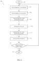
- the operating method 100 starts at step 102. Initially, the supports 23, the fluidic devices 21 and the containers 22, 24 are not coupled to the apparatus 1.
- the device 1 is turned on and acquires prescription data which are entered, either by the operator or in an automated manner, via the first interface means 85' and/or second interface means 85" (e.g., a server of a hospital facility comprising an archive with patient data).
- the prescription data are indicative of the prescription to be followed, i.e. the chemotherapy drug to be prepared for the patient under consideration.
- the prescription data include:
- a set-up of the apparatus 1 is also performed, for example performed in a controlled atmosphere (e.g., under a hood) and including:
- said assembly of the supports 23, of the fluidic devices 21 and of the containers 22, 24 to the apparatus 1 is performed by the operator or in an automated manner, and allows loading all the materials and/or objects necessary for the preparation of the specific chemotherapeutic drug.
- the supports 23, the fluidic devices 21 and the containers 22, 24 are identified by reading respective identification codes associated therewith.
- the supports 23, the fluidic devices 21 and the containers 22, 24 have either respective labels glued thereto and including respective barcodes, or respective radio frequency identification (“RFID”) labels, suitable for identifying them.
- RFID radio frequency identification
- the fluidic devices 21 and the first containers 22 are releasably fixed to each other, and then the fluidic devices 21 carrying the first containers 22 are coupled to the first rotor 9, as previously described.
- the supports 23 and the second containers 24 are releasably fixed to each other, and then the supports 23 carrying the second containers 24 are coupled to the second rotor 11, as previously described.
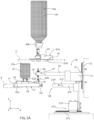
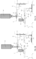
- step 104 by a positioning of the rotors 9, 11, shown in Figure 5A .
- the second rotor 11 rotates, by means of the first operating means 27, so as to bring the second selected container 24 closer to the operating device 5, said second container 24 being adapted to contain the chemotherapeutic drug of the patient under consideration.
- the first rotor 9 rotates, by means of the first operating means 27, so as to bring the selected first container 22 closer to the operating means 5, said first container 22 containing the ingredient to be inserted into the second container 24 to make the chemotherapeutic drug for the patient under consideration.
- the selected containers 22, 24 are therefore overlapping and at least partially aligned with each other parallel to the Z axis and face the side wall 5a of the operating device 5.
- the second operating means 70 couple the first needle 60 of the selected fluidic device 21 with the second selected container 24, said first needle 60 is used to achieve fluidic communication between the containers 22, 24 that have been selected.
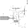
- step 108 consecutive to step 106, the third operating means 80 are coupled to the fluidic device 21, as further described below.
- step 110 consecutive to step 108, fluid is transferred from the first container 22 to the second container 24, as better described below.
- step 112 consecutive to step 110, the third operating means 80 are decoupled from the fluidic device 21, performing a reverse movement to that described with reference to step 108 and, hereinafter, Figure 5C .
- step 114 consecutive to step 112, the second operating means 70 displace the first needle 60 downwards (i.e. in the direction of the base 3 along the Z axis) and decouple the first needle 60 from the second container 24, interrupting fluidic communication between the containers 22, 24. In other words, a reverse movement to that described with reference to step 106 is made.
- step 116 consecutive to step 114, a condition on the composition of the chemotherapeutic drug to be prepared is verified. In particular, it is determined whether other ingredients (located in respective first containers 22 other than the previously considered first container 22) need to be added to the second container 24 to obtain the chemotherapeutic drug.
- step 116 If further ingredients are needed for the preparation of the chemotherapeutic drug (output "S" from step 116), the positioning of the rotors 9, 11 is performed again, thus returning to step 104. In particular, the first rotor 9 is operated to select the first container 22 of interest.
- the operating method 100 ends at a step 118, wherein, for example, the device 1 is turned off or will be awaiting a further order for a different preparation.
- a disassembly of the supports 23, of the fluidic devices 21 and of the containers 22, 24 from the apparatus 1 may be performed by the operator or in an automated manner, in order to prepare the apparatus 1 to perform step 102 again.
- an identification label for the second container 24 may be generated, for example, by means of said printing apparatus (included in the second interface means 85" and operatively coupled to the control unit 83).
- a label may include, for example, a barcode label or an RFID label.
- Such a label is adapted to be coupled (e.g., glued or fixed) to the second container 24, and is indicative of data such as the nature of the chemotherapeutic drug contained in the second container 24 (e.g., chemical composition and/or active substance contained) and/or an identifier of the patient to whom said chemotherapeutic drug is to be administered.
- the third operating means 80 are in a position decoupled from the piston 150, and are therefore in a rest position.
- the third operating means 80 are coupled to the piston 150 (step 108).
- the second translation means 272 translates along the X axis the second gripping means 274 so that the second end 150b of the piston 150 is interposed, parallel to the Y axis, between the end portions 274".
- the second gripping means 274 is coupled to the piston 150, placing the end portions 274" in the second operating condition so that they are releasably fixed to the second end 150b of the piston 150.
- the third operating means 80 cause part of the ingredient to be transferred from the first container 22 to the syringe 154.
- the second translation means 272 translates along the X axis the second gripping means 274 and the piston 150, thus moving the first end 150a of the piston 150 away from the end 156a of the body 156. In other words, it passes from the compression position of the first chamber 162a to the extension position of the first chamber 162a.
- This generates the first pressure gradient (and thus lower pressure at the second ends 168b, 176b than at the first ends 168a, 176a) which brings, when the first force is greater than the threshold force, the first valve 168 into the opening state (while the second valve 176 remains in the closing state).
- the first pressure gradient causes, together with the force of gravity, the transfer of the ingredient from the first container 22 to the first chamber 162a of the syringe 154.
- a movement (not shown) of the third operating means 80 opposite to that shown in Figure 5D causes the transfer of part of the ingredient from the syringe 154 to the second container 24.
- the second translation means 272 translates again along the X axis the second gripping means 274 and the piston 150 in the opposite direction with respect to the moment described with reference to Figure 5D , thus bringing the first end 150a of the piston 150 closer to the end 156a of the body 156.
- the second pressure gradient causes the transfer of the ingredient from the first chamber 162a of the syringe 154 to the second container 24.
- the expansion and compression movements of the first chamber 162a operated by the third operating means 80 allow the transfer of the ingredient from the first container 22 to the second container 24 (step 110).
- the apparatus 1 is an automated system for the preparation of anticancer drugs, capable of overcoming the critical elements connected with the manual preparation thereof and of ensuring a substantial increase in the quality of cancer therapies.
- the apparatus 1 allows a significant increase in formulation accuracy, a significant reduction of chemical contamination of the environments intended for the preparation of such drugs and a drastic reduction of the professional risk for the healthcare workers assigned thereto.
- the apparatus 1 implements, via the control unit 83, a computerised procedure for managing chemotherapy preparations, for use for example by hospital pharmacies.
- This computerised procedure can be interfaced with a hospital information system (if any) through standard communication protocols.
- the apparatus 1 is an automated table-top device, which can be easily inserted into a laminar flow hood for chemotherapy.
- the apparatus 1 may be operated under a vertical laminar flow hood of ISO class 5, which in turn is placed in an ISO class 8 air-controlled environment.
- the communication between the control unit 83 and the second interface means 85" takes place in wireless mode, in order to eliminate any wired connection between a sterile interior of the hood in which the apparatus 1 is positioned and the external environment.
- the apparatus 1 allows the adoption of a closed circuit fluidic system able to guarantee sterility during the transfer of the chemotherapeutic drug from the first container 22 to the second container 24, and the absence of contamination of the surrounding environment.
- the fluidic device 21 is made of low-cost plastic materials for medical use, such as polystyrene, polycarbonate, polyurethane or PVC and has a structure that is easy to manufacture. This ensures reduced manufacturing costs and allows for single use, of the disposable type. In other words, the fluidic device 21 is coupled only once to the respective first container 22, and after the transfer of the respective ingredient it is thrown away. This significantly reduces the risk of contamination for patients and healthcare workers.
- the fluidic device 21 is a standardised interface allowing the coupling of different types of first containers 22 to the first rotor 9.
- the chemotherapy drug is dosed directly into the second containers 24, which are the final containers intended for administration to the patient. This avoids the need for further and subsequent handling, which could be a source of further contamination.
- Each second container 24 is identified by a code (e.g. QR) with the details of the chemotherapy drug preparation and of the patient for whom it is intended. This information is therefore verifiable at the time of administration in order to prevent possible accidental exchange of drugs.
- QR a code
- the fluidic group 21 allows the connection, commanded by the second operating means 70 of the apparatus 1, between the first container 22 (i.e. the bottle with the selected ingredient) and the second container 24 (or final container of the drug, i.e. bag, syringe, etc.), aimed at transferring the ingredient itself in the predetermined quantity controlled by the apparatus 1.
- this connection with the fluidic group 21 is permanent and is consequent to the perforation of the first cap 22b by the interface means 171 and to the engagement of the metal capsule of the first cap 22b by a ring nut (e.g., of plastic) of the interface means 171.
- this connection with the fluidic unit 21 is made by means of the second operating means 70, which provide for the insertion of the first needle 60 (i.e., a non-valved male luer-slip connector) into a female luer-lock connector (valved) previously coupled to the second container 24 (in detail, inserted into the second cap 24b).
- the first needle 60 i.e., a non-valved male luer-slip connector
- valved previously coupled to the second container 24 (in detail, inserted into the second cap 24b).
- the first needle 60 makes it possible to use the fluidic device 21 in the automated apparatus 1.
- the first operating means 27 may also be arranged in the base 3 instead of in the operating means 5.
- the second rotor 11 may be replaced by a support structure (not shown) fixed to the base 3 (therefore not rotatable) in the event that only a second container 24 can be coupled to the apparatus 1.
- a support structure not shown
- said second container 24 is removed and replaced, automatically or manually, with a further second container 24 to proceed to a further preparation of chemotherapeutic drug.
- the apparatus 1 may also be used in the preparation of drugs other than chemotherapeutic drugs, for example injectable drugs such as monoclonal antibodies, cytotoxics, hormones and hormone antagonists, antimitotics, alkylating agents, antibiotics.
- injectable drugs such as monoclonal antibodies, cytotoxics, hormones and hormone antagonists, antimitotics, alkylating agents, antibiotics.
Landscapes
- Health & Medical Sciences (AREA)
- Life Sciences & Earth Sciences (AREA)
- Animal Behavior & Ethology (AREA)
- General Health & Medical Sciences (AREA)
- Public Health (AREA)
- Veterinary Medicine (AREA)
- Pharmacology & Pharmacy (AREA)
- Biomedical Technology (AREA)
- Vascular Medicine (AREA)
- Engineering & Computer Science (AREA)
- Anesthesiology (AREA)
- Heart & Thoracic Surgery (AREA)
- Hematology (AREA)
- Fluid Mechanics (AREA)
- Physics & Mathematics (AREA)
- Infusion, Injection, And Reservoir Apparatuses (AREA)
- Medicinal Preparation (AREA)
Claims (16)
- Fluidgruppe (21), die an einen ersten Behälter (24) koppelbar ist, der ein erstes Innenvolumen definiert, das geeignet ist, ein Arzneimittel zu enthalten, und an einen zweiten Behälter (22)koppelbar ist, der ein zweites Innenvolumen definiert, das geeignet ist, einen Inhaltsstoff zum Vorbereiten des Arzneimittels zu enthalten, wobei die Fluidgruppe einen ersten Körper (59) umfasst, der einen ersten Hohlraum (59a) definiert und umfassend:- eine Spritze (154), die einen zweiten Körper (156) umfasst, der einen zweiten Hohlraum (158) definiert, der einen Kolben (150) aufnimmt, der in dem zweiten Körper (156) beweglich ist und mit dem zweiten Körper (156) eine Kammer (162a) definiert, die ein veränderliches Volumen nach einer Position des Kolbens (150) in dem zweiten Hohlraum (158) aufweist;- eine erste Kupplungsgruppe (171, 172), die sich teilweise außerhalb des ersten Hohlraums (59a) erstreckt und lösbar an dem zweiten Behälter (22) befestigt werden kann, sodass sie in Fluidverbindung mit dem zweiten Innenvolumen steht;- eine zweite Kupplungsgruppe (25), die sich teilweise außerhalb des ersten Hohlraums (59a) erstreckt und lösbar an dem ersten Behälter (24) befestigt werden kann, sodass sie in Fluidverbindung mit dem ersten Innenvolumen steht;- ein Gabelungselement (166) aufweisen einen ersten (166') und einen zweiten (166") Einlass, die in Fluidverbindung mit der ersten Kupplungsgruppe (171, 172) und bzw. mit der zweiten Kupplungsgruppe (25) angeordnet sind, und ferner aufweisend einen dritten Einlass (166‴) in Fluidverbindung mit der Kammer (162a), wobei der dritte Einlass ferner mit dem ersten und dem zweiten Einlass kommuniziert, um einen ersten Fluidweg zwischen dem zweiten Innenvolumen und der Kammer (162a) und einen zweiten Fluidweg zwischen der Kammer (162a) und dem ersten Innenvolumen zu schaffen;- ein erstes Einwegventil (168), das entlang des ersten Fluidwegs zwischen der ersten Kupplungsgruppe (171, 172) und dem Gabelungselement (166) angeordnet ist und nach einem ersten Druckgradienten, der durch eine Bewegung des Kolbens (150) in dem Hohlraum (158) verursacht wird, gesteuert werden kann, um den Durchgang des Inhaltsstoffs von dem zweiten Behälter (22) zu der Kammer (162a) der Spritze (154) zu ermöglichen; und- ein zweites Einwegventil (176), das entlang des zweiten Fluidwegs zwischen der zweiten Kupplungsgruppe (25) und dem Gabelungselement (166) angeordnet ist und nach einem zweiten Druckgradienten, der dem ersten Druckgradienten entgegengesetzt ist, gesteuert werden kann, um den Durchgang von der Kammer (162a) zu dem ersten Behälter (24) des aus dem zweiten Behälter (22) in die Kammer (162a) der Spritze (154) übertragenen Inhaltsstoff zu ermöglichen.
- Fluidgruppe nach Anspruch 1, wobei der zweite Körper (156) einen ersten (156a) und einen zweiten (156b) Endabschnitt aufweist, die einander gegenüberliegen, wobei die Kammer (162a) mit dem dritten Einlass (166‴) an dem ersten Endabschnitt (156a) in Fluidverbindung steht,wobei der Kolben (150) ein Dichtungselement (150') umfasst, das mit dem zweiten Körper (156) die Kammer (162a) definiert und das in den zweiten Körper (156) zwischen einer ersten Position und einer zweiten Position in Bezug auf den zweiten Körper (156) fluiddicht gleitet,wobei, wenn sich das Dichtungselement (150') in der ersten Position befindet, das Dichtungselement (150') einen ersten Abstand von dem ersten Endabschnitt (156a) des zweiten Körpers (156) aufweist und die Kammer (162a) ein erstes Volumen aufweist,und wobei, wenn sich das Dichtungselement (150') in der zweiten Position befindet, das Dichtungselement (150') einen zweiten Abstand von dem ersten Endabschnitt (156a) des zweiten Körpers (156) aufweist und die Kammer (162a) ein zweites Volumen aufweist, wobei der zweite Abstand größer als der erste Abstand ist und das zweite Volumen größer als das erste Volumen ist.
- Fluidgruppe nach einem der vorhergehenden Ansprüche, wobei Pumpenmittel (80) lösbar mit dem Kolben (150) koppelbar sind und wobei sie betätigbar sind, um den ersten Druckgradienten oder den zweiten Druckgradienten durch Bewegen des Kolbens (150) in dem zweiten Hohlraum (158) erzeugen zu können.
- Fluidgruppe nach Anspruch 2 und Anspruch 3, wobei das erste Ventil (168) betätigbar ist, um von einem ersten Schließzustand zu einem ersten Öffnungszustand überzugehen, und das zweite Ventil (176) betätigbar ist, um von einem zweiten Schließzustand zu einem zweiten Öffnungszustand überzugehen,und wobei, wenn das Dichtungselement (150') durch die Pumpenmittel (80) von der ersten Position in die zweite Position bewegt wird, der erste Druckgradient eine Kraft ausübt, sodass sich das erste Ventil (168) in dem ersten Öffnungszustand und sich das zweite Ventil (176) in dem zweiten Schließzustand befindet,und wenn das Dichtungselement (150') durch die Pumpenmittel (80) von der zweiten Position in die erste Position bewegt wird, der zweite Druckgradient eine weitere Kraft ausübt, sodass sich das erste Ventil (168) in dem ersten Schließzustand befindet und sich das zweite Ventil (176) in dem zweiten Öffnungszustand befindet.
- Fluidgruppe nach einem der vorhergehenden Ansprüche, wobei die zweite Kupplungsgruppe (25) ein erstes flexibles Rohrelement (62) und eine erste Hohlnadel (60) umfasst, die über das erste Rohrelement (62) mit dem zweiten Ventil (176) in Fluidkopplung steht,
wobei die erste Hohlnadel (60) in Bezug auf den ersten Körper (59) beweglich ist und in eine erste Kappe (24b) des ersten Behälters (24) eingeführt werden kann, um die Fluidverbindung zwischen der Kammer (162a) der Spritze (154) und dem ersten Innenvolumen zu ermöglichen. - Fluidgruppe nach Anspruch 5, wobei der erste Körper (59) eine erste Oberfläche (59') aufweist, die dem zweiten Behälter (22) zugewandt werden kann,wobei die erste Hohlnadel (60) durch einen ersten Stützabschnitt (152) des ersten Körpers (59), der sich ausgehend von und senkrecht zu der ersten Oberfläche (59') erstreckt, lösbar gestützt wird,wobei die erste Hohlnadel (60) ein erstes (60a) und ein zweites (60b) Ende aufweist, die einander gegenüberliegen, wobei das zweite Ende (60b) an dem ersten Rohrelement (62) befestigt wird,und wobei die erste Hohlnadel (60) von dem ersten Stützabschnitt (152) gestützt wird, sodass das zweite Ende (60b) der ersten Oberfläche (59') zugewandt werden kann und das erste Ende (60a) der ersten Kappe (24b) des ersten Behälters (24) zugewandt werden kann.
- Fluidgruppe nach einem der vorhergehenden Ansprüche, wobei die erste Kupplungsgruppe (171, 172) einen zweiten Stützabschnitt (171b) umfasst, der an dem ersten Körper (59) befestigt ist, der sich außerhalb des ersten Hohlraums (59a) erstreckt und der konfiguriert ist, den zweiten Behälter (22) zu stützen,
der zweite Stützabschnitt (171b) eine zweite Hohlnadel (171a) umfasst, die in Fluidverbindung mit dem ersten Einlass (166') durch das erste Ventil (168) steht, wobei die zweite Hohlnadel (171a) in eine zweite Kappe (22b) des zweiten Behälters (22) eingeführt werden kann, um die Fluidverbindung zwischen dem zweiten Innenvolumen und der Kammer (162a) der Spritze (154) zu ermöglichen. - Apparat (1) zum Vorbereiten von Arzneimitteln aus mindestens einem Inhaltsstoff, wobei der Apparat (1) dadurch gekennzeichnet ist, dass er umfasst:- ein erstes Stützelement (11), das konfiguriert ist, mindestens einen ersten Behälter (24) zu stützen, der geeignet ist, das Arzneimittel zu enthalten, und der lösbar auf dem ersten Stützelement (11) angeordnet werden kann;- mindestens eine Fluidgruppe (21) nach Anspruch 1;- ein zweites Stützelement (9), das die mindestens eine Fluidgruppe (21) stützt, wobei die mindestens eine Fluidgruppe (21) lösbar auf dem zweiten Stützelement (9) angeordnet ist und lösbar mit einem jeweiligen zweiten Behälter (22) koppelbar ist, der geeignet ist, einen jeweiligen Inhaltsstoff zu enthalten;- eine Steuereinheit (83);- Verbindungsmittel (70), die mit dem ersten Behälter (24) und dem zweiten Behälter (22) koppelbar sind und operativ mit der Steuereinheit (83) gekoppelt sind, wobei die Verbindungsmittel (70) durch die Steuereinheit (83) steuerbar sind, um die zweite Kopplungsgruppe (25) mit dem ersten Behälter (24) zu koppeln, um den zweiten Behälter (22) mit dem ersten Behälter (24) in Fluidverbindung zu bringen; und- Pumpenmittel (80), die mit der Fluidgruppe (21) gekoppelt sind und operativ mit der Steuereinheit (83) gekoppelt sind, wobei die Pumpenmittel (80) durch die Steuereinheit (83) steuerbar sind, um das Inhaltsstoff zumindest teilweise aus dem zweiten Behälter (22) in den ersten Behälter (24) zu übertragen.
- Apparat nach Anspruch 8, ferner umfassend eine Basis (3) aufweisend eine zweite Oberfläche (3a), an die das erste Stützelement (11) und das zweite Stützelement (9) gekoppelt sind,wobei das erste Stützelement (11) und das zweite Stützelement (9) sich parallel zu der zweiten Fläche (3a) erstrecken und koaxial zueinander in Bezug auf eine Drehachse (15) senkrecht zu der zweiten Fläche (3a) angeordnet sind,das zweite Stützelement (9) in Bezug auf die Drehachse (15)axial zwischen dem ersten Stützelement (11) und der zweiten Fläche (3a) angeordnet ist und in Bezug auf die Basis (3) um die Drehachse (15) drehbar ist
- Apparat nach Anspruch 9, wobei das zweite Stützelement (9) in Bezug auf die Basis (3) um die Drehachse (15) drehbar ist und konfiguriert ist, den zweiten Behälter (22) mittels der Fluidgruppe (21) und mindestens einen weiteren zweiten Behälter (22) mittels einer weiteren Fluidgruppe (21) lösbar zu stützen.
- Apparat nach Anspruch 9 oder Anspruch 10, wobei das erste Stützelement (11) in Bezug auf die Basis (3) um die Drehachse (15) drehbar ist und konfiguriert ist, den ersten Behälter (24) und mindestens einen weiteren ersten Behälter (24) lösbar zu stützen.
- Apparat nach Anspruch 10 und Anspruch 11 ferner umfassend erste Betätigungsmittel (27), die durch die Steuereinheit (83) steuerbar sind und konfiguriert sind, das erste Stützelement (11) und das zweite Stützelement (9) unabhängig voneinander in Bezug auf die Basis (3) um die Drehachse (15) zu drehen, so dass ein erster ausgewählter Behälter (24) und ein zweiter ausgewählter Behälter (22) in jeweiligen Winkelpositionen angeordnet werden können, so dass sie den Verbindungsmitteln (70) und den Pumpenmitteln (80) zugewandt sind.
- Apparat nach einem der Ansprüche 9 bis 12, wobei die Verbindungsmittel (70) umfassen:ein erstes Führungselement (73), das an der Basis (3) befestigt wird und einen ersten Weg definiert, der sich parallel zu einer ersten Achse (Z) erstreckt;ein erstes bewegliches Element (75), das mit dem ersten Führungselement (73) gekoppelt ist, sodass es sich entlang des ersten Weges bewegt; undein erstes Greifmittel (74), das an dem ersten beweglichen Element (75) befestigt wird und durch die Steuereinheit (83) steuerbar ist, um lösbar mit der zweiten Kupplungsgruppe (25) zu koppeln,wobei die Verbindungsmittel (70) durch die Steuereinheit (83) steuerbar sind, um über die ersten Greifmittel (74) mit der zweiten Kupplungsgruppe (25) zu koppeln und anschließend die zweite Kupplungsgruppe (25) entlang des ersten Weges zu bewegen, um die zweite Kupplungsgruppe (25) mit dem ersten Behälter (24) zu koppeln, wodurch eine Verbindung mit einem Fluid-Durchgang geschaffen wird.
- Apparat nach Anspruch 13, wobei die Pumpenmittel (80) umfassen:- ein zweites Führungselement (273), das an der Basis (3) befestigt wird und einen zweiten Weg definiert, der sich parallel zu einer zweiten Achse (X) orthogonal zur ersten Achse (Z) erstreckt;- ein zweites bewegliches Element (275), das mit dem zweiten Führungselement (273) gekoppelt ist, sodass es sich entlang des zweiten Weges bewegt; und- ein zweites Greifmittel (274), das an dem zweiten beweglichen Element (275) befestigt wird und durch die Steuereinheit (83) steuerbar ist kann, um mit dem Kolben (150) lösbar zu koppeln,wobei die Pumpenmittel (80) durch die Steuereinheit (83) steuerbar sind, um mittels des zweiten Greifmittels (274) mit dem Kolben (150) zu koppeln und anschließend das zweite bewegliche Element (275) in Bezug auf das zweite Führungselement (273) entlang des zweiten Weges zu bewegen, wodurch der Kolben (150) in dem zweiten Hohlraum (158) bewegt wird und der erste Druckgradient oder der zweite Druckgradient erzeugt wird.
- Apparat nach Anspruch 14 und Anspruch 2, wobei das erste Ventil (168) betätigbar ist, um von einem ersten Schließzustand zu einem ersten Öffnungszustand überzugehen, und das zweite Ventil (176) betätigbar ist, um von einem zweiten Schließzustand zu einem zweiten Öffnungszustand überzugehen,wobei die Pumpenmittel (80) durch die Steuereinheit (83) steuerbar sind, um das Dichtungselement (150') von der ersten Position in die zweite Position zu bewegen, wobei der erste Druckgradient eine Kraft ausübt, sodass sich das erste Ventil (168) in dem ersten Öffnungszustand befindet und sich das zweite Ventil (176) in dem zweiten Schließzustand befindet, um den Durchgang des Inhaltsstoffs aus dem zweiten Behälter (22) in die Kammer (162a) der Spritze (154) zu ermöglichen,und wobei die Pumpenmittel (80) durch die Steuereinheit (83) steuerbar sind, um das Dichtungselement (150') von der zweiten Position in die erste Position zu bewegen, wobei der zweite Druckgradient eine Kraft ausübt, so dass sich das erste Ventil (168) in dem ersten Schließzustand befindet und sich das zweite Ventil (176) in dem zweiten Öffnungszustand befindet, um den Durchgang des aus dem zweiten Behälter (22) in die Kammer (162a) übertragenen Inhaltsstoffes von der Kammer (162a) der Spritze (154) zu dem ersten Behälter (24) zu ermöglichen.
- Apparat nach einem der Ansprüche 8 bis 15, wobei die Steuereinheit (83) operativ mit einem Druckapparat (85") gekoppelt ist, der durch die Steuereinheit (83) steuerbar ist, um ein Schild zu erzeugen, das eingerichtet ist, mit dem ersten Behälter (24) gekoppelt zu werden und das das Arzneimittel identifiziert.
Applications Claiming Priority (2)
| Application Number | Priority Date | Filing Date | Title |
|---|---|---|---|
| IT102020000009751A IT202000009751A1 (it) | 2020-05-04 | 2020-05-04 | Gruppo fluidico e relativo apparecchio per la preparazione di farmaci |
| PCT/IB2021/053733 WO2021224791A1 (en) | 2020-05-04 | 2021-05-04 | Fluidic group and related apparatus for drug preparation |
Publications (3)
| Publication Number | Publication Date |
|---|---|
| EP4146135A1 EP4146135A1 (de) | 2023-03-15 |
| EP4146135C0 EP4146135C0 (de) | 2025-01-29 |
| EP4146135B1 true EP4146135B1 (de) | 2025-01-29 |
Family
ID=71784405
Family Applications (1)
| Application Number | Title | Priority Date | Filing Date |
|---|---|---|---|
| EP21729931.2A Active EP4146135B1 (de) | 2020-05-04 | 2021-05-04 | Fluidische gruppe und zugehörige vorrichtung zur arzneimittelherstellung |
Country Status (6)
| Country | Link |
|---|---|
| US (1) | US12396926B2 (de) |
| EP (1) | EP4146135B1 (de) |
| CN (1) | CN115768392A (de) |
| ES (1) | ES3011482T3 (de) |
| IT (1) | IT202000009751A1 (de) |
| WO (1) | WO2021224791A1 (de) |
Family Cites Families (15)
| Publication number | Priority date | Publication date | Assignee | Title |
|---|---|---|---|---|
| EP2012735A1 (de) * | 2006-04-24 | 2009-01-14 | Novo Nordisk A/S | Transfersystem zur bildung einer arzneilösung aus einem lyophilisierten arzneimittel |
| JP5449373B2 (ja) * | 2008-10-15 | 2014-03-19 | ノボ ノルディスク ヘルス ケア アーゲー | 粉末状薬剤の復元のためのシステム |
| US9399095B2 (en) * | 2009-05-27 | 2016-07-26 | David R. Duncan | Compact non-electric medicament infuser |
| JP5794517B2 (ja) * | 2010-12-28 | 2015-10-14 | 株式会社タカゾノテクノロジー | 水剤供給装置 |
| KR101221483B1 (ko) * | 2011-05-13 | 2013-01-16 | 서강대학교산학협력단 | F-18 표지 방사성의약품 합성 장치 및 방법 |
| ITMO20120219A1 (it) * | 2012-09-17 | 2014-03-18 | Giuseppe Maffei | Apparecchiatura per il trasferimento di fluidi biomedicali tra recipienti ospedalieri |
| EP4144390A3 (de) * | 2013-06-18 | 2023-07-12 | Enable Injections, Inc. | Phiolenübertragungs- und -injektionsvorrichtung und -verfahren |
| CA2920835A1 (en) * | 2013-08-20 | 2015-02-26 | Anutra Medical, Inc. | Syringe fill system and method |
| ITTO20130925A1 (it) * | 2013-11-14 | 2015-05-15 | Eltek Spa | Dispositivo medicale, in particolare per la separazione di un fluido |
| AU2014353184B2 (en) * | 2013-11-25 | 2017-08-17 | Icu Medical, Inc. | Methods and system for filling IV bags with therapeutic fluid |
| IL239366B (en) * | 2015-06-11 | 2018-07-31 | Kriheli Marino | Components of a fluid transfer apparatus |
| US10925808B2 (en) * | 2015-12-04 | 2021-02-23 | Carefusion 303, Inc. | Tube management structures for automatic drug compounder |
| WO2017096072A1 (en) * | 2015-12-04 | 2017-06-08 | Icu Medical, Inc. | Systems methods and components for transferring medical fluids |
| KR102776224B1 (ko) * | 2018-05-11 | 2025-03-10 | 브리스톨-마이어스 스큅 컴퍼니 | 조합 치료법의 전달을 위한 장치 및 시스템 |
| EP4037633A4 (de) * | 2019-09-30 | 2023-10-04 | Becton, Dickinson and Company | Medikamentenabfüllsystem |
-
2020
- 2020-05-04 IT IT102020000009751A patent/IT202000009751A1/it unknown
-
2021
- 2021-05-04 US US17/922,649 patent/US12396926B2/en active Active
- 2021-05-04 WO PCT/IB2021/053733 patent/WO2021224791A1/en not_active Ceased
- 2021-05-04 CN CN202180036085.7A patent/CN115768392A/zh active Pending
- 2021-05-04 ES ES21729931T patent/ES3011482T3/es active Active
- 2021-05-04 EP EP21729931.2A patent/EP4146135B1/de active Active
Also Published As
| Publication number | Publication date |
|---|---|
| EP4146135C0 (de) | 2025-01-29 |
| WO2021224791A1 (en) | 2021-11-11 |
| US12396926B2 (en) | 2025-08-26 |
| ES3011482T3 (en) | 2025-04-07 |
| EP4146135A1 (de) | 2023-03-15 |
| CN115768392A (zh) | 2023-03-07 |
| IT202000009751A1 (it) | 2021-11-04 |
| US20230165754A1 (en) | 2023-06-01 |
Similar Documents
| Publication | Publication Date | Title |
|---|---|---|
| JP7299402B2 (ja) | 調合デバイス、システム、キット、ソフトウエア、および方法 | |
| ES2384193T5 (es) | Aparato para la preparación automática de un medicamento y correspondiente procedimiento de preparación | |
| EP2258333B1 (de) | Vorrichtung zum Befüllen eines flexiblen Behälters | |
| ES2856339T3 (es) | Sistema robótico para la composición de medicamentos | |
| EP2437715B1 (de) | Transfer- und ausbringungsvorrichtung für mehrere container | |
| EP3027162B1 (de) | Compoundierungssysteme und verfahren für sicheren medikamententransport | |
| EP2661290B1 (de) | Integriertes pumpmodul | |
| JP7616776B2 (ja) | 注射剤調剤キット及びこれを含む注射剤調剤システム | |
| US20160114109A1 (en) | System and method for preparing and delivering a medicament | |
| JP7720459B2 (ja) | 直列接続可能な薬剤モジュールの代替流体経路 | |
| KR20130100060A (ko) | 다중 용기 유체 이송 및 공급 장치 | |
| CN109715122B (zh) | 用于iv流体的复溶装置及使用方法 | |
| EP4146135B1 (de) | Fluidische gruppe und zugehörige vorrichtung zur arzneimittelherstellung | |
| US10835881B2 (en) | Mixing device and methods thereof | |
| EP4121140B1 (de) | Abgabevorrichtung zur verabreichung eines medikaments | |
| EP3431121A1 (de) | Medizinisches flüssigkeitsübertragungssystem und verfahren zur verwendung | |
| EP4146136B1 (de) | Vorrichtung zur arzneimittelherstellung, in der vorrichtung enthaltene wiegevorrichtung und verfahren zur arzneimittelherstellung | |
| CN114727905B (zh) | 用于组合药物递送装置的可串联连接的药物模块的活塞阀 | |
| JP2009530363A (ja) | 抗芽球薬の希釈および調合の装置および方法 | |
| KR20230058943A (ko) | 주사제 조제 장치 | |
| EP4438500A1 (de) | Vorrichtung zur übertragung einer medizinischen flüssigkeit |
Legal Events
| Date | Code | Title | Description |
|---|---|---|---|
| STAA | Information on the status of an ep patent application or granted ep patent |
Free format text: STATUS: UNKNOWN |
|
| STAA | Information on the status of an ep patent application or granted ep patent |
Free format text: STATUS: THE INTERNATIONAL PUBLICATION HAS BEEN MADE |
|
| PUAI | Public reference made under article 153(3) epc to a published international application that has entered the european phase |
Free format text: ORIGINAL CODE: 0009012 |
|
| STAA | Information on the status of an ep patent application or granted ep patent |
Free format text: STATUS: REQUEST FOR EXAMINATION WAS MADE |
|
| 17P | Request for examination filed |
Effective date: 20221128 |
|
| AK | Designated contracting states |
Kind code of ref document: A1 Designated state(s): AL AT BE BG CH CY CZ DE DK EE ES FI FR GB GR HR HU IE IS IT LI LT LU LV MC MK MT NL NO PL PT RO RS SE SI SK SM TR |
|
| RAV | Requested validation state of the european patent: fee paid |
Extension state: MD Effective date: 20221128 |
|
| GRAP | Despatch of communication of intention to grant a patent |
Free format text: ORIGINAL CODE: EPIDOSNIGR1 |
|
| STAA | Information on the status of an ep patent application or granted ep patent |
Free format text: STATUS: GRANT OF PATENT IS INTENDED |
|
| INTG | Intention to grant announced |
Effective date: 20240820 |
|
| GRAS | Grant fee paid |
Free format text: ORIGINAL CODE: EPIDOSNIGR3 |
|
| GRAA | (expected) grant |
Free format text: ORIGINAL CODE: 0009210 |
|
| STAA | Information on the status of an ep patent application or granted ep patent |
Free format text: STATUS: THE PATENT HAS BEEN GRANTED |
|
| AK | Designated contracting states |
Kind code of ref document: B1 Designated state(s): AL AT BE BG CH CY CZ DE DK EE ES FI FR GB GR HR HU IE IS IT LI LT LU LV MC MK MT NL NO PL PT RO RS SE SI SK SM TR |
|
| REG | Reference to a national code |
Ref country code: GB Ref legal event code: FG4D |
|
| REG | Reference to a national code |
Ref country code: CH Ref legal event code: EP |
|
| REG | Reference to a national code |
Ref country code: DE Ref legal event code: R096 Ref document number: 602021025405 Country of ref document: DE |
|
| REG | Reference to a national code |
Ref country code: IE Ref legal event code: FG4D |
|
| U01 | Request for unitary effect filed |
Effective date: 20250129 |
|
| U07 | Unitary effect registered |
Designated state(s): AT BE BG DE DK EE FI FR IT LT LU LV MT NL PT RO SE SI Effective date: 20250205 |
|
| REG | Reference to a national code |
Ref country code: ES Ref legal event code: FG2A Ref document number: 3011482 Country of ref document: ES Kind code of ref document: T3 Effective date: 20250407 |
|
| U20 | Renewal fee for the european patent with unitary effect paid |
Year of fee payment: 5 Effective date: 20250422 |
|
| PG25 | Lapsed in a contracting state [announced via postgrant information from national office to epo] |
Ref country code: RS Free format text: LAPSE BECAUSE OF FAILURE TO SUBMIT A TRANSLATION OF THE DESCRIPTION OR TO PAY THE FEE WITHIN THE PRESCRIBED TIME-LIMIT Effective date: 20250429 |
|
| PG25 | Lapsed in a contracting state [announced via postgrant information from national office to epo] |
Ref country code: PL Free format text: LAPSE BECAUSE OF FAILURE TO SUBMIT A TRANSLATION OF THE DESCRIPTION OR TO PAY THE FEE WITHIN THE PRESCRIBED TIME-LIMIT Effective date: 20250129 |
|
| PGFP | Annual fee paid to national office [announced via postgrant information from national office to epo] |
Ref country code: ES Payment date: 20250611 Year of fee payment: 5 |
|
| PG25 | Lapsed in a contracting state [announced via postgrant information from national office to epo] |
Ref country code: NO Free format text: LAPSE BECAUSE OF FAILURE TO SUBMIT A TRANSLATION OF THE DESCRIPTION OR TO PAY THE FEE WITHIN THE PRESCRIBED TIME-LIMIT Effective date: 20250429 Ref country code: IS Free format text: LAPSE BECAUSE OF FAILURE TO SUBMIT A TRANSLATION OF THE DESCRIPTION OR TO PAY THE FEE WITHIN THE PRESCRIBED TIME-LIMIT Effective date: 20250529 |
|
| PG25 | Lapsed in a contracting state [announced via postgrant information from national office to epo] |
Ref country code: HR Free format text: LAPSE BECAUSE OF FAILURE TO SUBMIT A TRANSLATION OF THE DESCRIPTION OR TO PAY THE FEE WITHIN THE PRESCRIBED TIME-LIMIT Effective date: 20250129 |
|
| PG25 | Lapsed in a contracting state [announced via postgrant information from national office to epo] |
Ref country code: GR Free format text: LAPSE BECAUSE OF FAILURE TO SUBMIT A TRANSLATION OF THE DESCRIPTION OR TO PAY THE FEE WITHIN THE PRESCRIBED TIME-LIMIT Effective date: 20250430 |
|
| PGFP | Annual fee paid to national office [announced via postgrant information from national office to epo] |
Ref country code: CH Payment date: 20250601 Year of fee payment: 5 |
|
| PGFP | Annual fee paid to national office [announced via postgrant information from national office to epo] |
Ref country code: IE Payment date: 20250520 Year of fee payment: 5 |
|
| PG25 | Lapsed in a contracting state [announced via postgrant information from national office to epo] |
Ref country code: SM Free format text: LAPSE BECAUSE OF FAILURE TO SUBMIT A TRANSLATION OF THE DESCRIPTION OR TO PAY THE FEE WITHIN THE PRESCRIBED TIME-LIMIT Effective date: 20250129 |
|
| VS25 | Lapsed in a validation state [announced via postgrant information from nat. office to epo] |
Ref country code: MD Free format text: LAPSE BECAUSE OF FAILURE TO SUBMIT A TRANSLATION OF THE DESCRIPTION OR TO PAY THE FEE WITHIN THE PRESCRIBED TIME-LIMIT Effective date: 20250129 |
|
| PG25 | Lapsed in a contracting state [announced via postgrant information from national office to epo] |
Ref country code: CZ Free format text: LAPSE BECAUSE OF FAILURE TO SUBMIT A TRANSLATION OF THE DESCRIPTION OR TO PAY THE FEE WITHIN THE PRESCRIBED TIME-LIMIT Effective date: 20250129 |
|
| PG25 | Lapsed in a contracting state [announced via postgrant information from national office to epo] |
Ref country code: SK Free format text: LAPSE BECAUSE OF FAILURE TO SUBMIT A TRANSLATION OF THE DESCRIPTION OR TO PAY THE FEE WITHIN THE PRESCRIBED TIME-LIMIT Effective date: 20250129 |
|
| PLBE | No opposition filed within time limit |
Free format text: ORIGINAL CODE: 0009261 |
|
| STAA | Information on the status of an ep patent application or granted ep patent |
Free format text: STATUS: NO OPPOSITION FILED WITHIN TIME LIMIT |
|
| 26N | No opposition filed |
Effective date: 20251030 |
|
| GBPC | Gb: european patent ceased through non-payment of renewal fee |
Effective date: 20250504 |
|
| PG25 | Lapsed in a contracting state [announced via postgrant information from national office to epo] |
Ref country code: MC Free format text: LAPSE BECAUSE OF FAILURE TO SUBMIT A TRANSLATION OF THE DESCRIPTION OR TO PAY THE FEE WITHIN THE PRESCRIBED TIME-LIMIT Effective date: 20250129 |
|
| PG25 | Lapsed in a contracting state [announced via postgrant information from national office to epo] |
Ref country code: GB Free format text: LAPSE BECAUSE OF NON-PAYMENT OF DUE FEES Effective date: 20250504 |