EP4146453B1 - Procédé de production d'une bande de fixation - Google Patents
Procédé de production d'une bande de fixation Download PDFInfo
- Publication number
- EP4146453B1 EP4146453B1 EP21735859.7A EP21735859A EP4146453B1 EP 4146453 B1 EP4146453 B1 EP 4146453B1 EP 21735859 A EP21735859 A EP 21735859A EP 4146453 B1 EP4146453 B1 EP 4146453B1
- Authority
- EP
- European Patent Office
- Prior art keywords
- strip
- embossing
- structured
- panel
- embossed
- Prior art date
- Legal status (The legal status is an assumption and is not a legal conclusion. Google has not performed a legal analysis and makes no representation as to the accuracy of the status listed.)
- Active
Links
Images


Classifications
-
- B—PERFORMING OPERATIONS; TRANSPORTING
- B29—WORKING OF PLASTICS; WORKING OF SUBSTANCES IN A PLASTIC STATE IN GENERAL
- B29C—SHAPING OR JOINING OF PLASTICS; SHAPING OF MATERIAL IN A PLASTIC STATE, NOT OTHERWISE PROVIDED FOR; AFTER-TREATMENT OF THE SHAPED PRODUCTS, e.g. REPAIRING
- B29C63/00—Lining or sheathing, i.e. applying preformed layers or sheathings of plastics; Apparatus therefor
- B29C63/0026—Lining or sheathing, i.e. applying preformed layers or sheathings of plastics; Apparatus therefor an edge face with strip material, e.g. a panel edge
-
- B—PERFORMING OPERATIONS; TRANSPORTING
- B29—WORKING OF PLASTICS; WORKING OF SUBSTANCES IN A PLASTIC STATE IN GENERAL
- B29C—SHAPING OR JOINING OF PLASTICS; SHAPING OF MATERIAL IN A PLASTIC STATE, NOT OTHERWISE PROVIDED FOR; AFTER-TREATMENT OF THE SHAPED PRODUCTS, e.g. REPAIRING
- B29C59/00—Surface shaping of articles, e.g. embossing; Apparatus therefor
- B29C59/02—Surface shaping of articles, e.g. embossing; Apparatus therefor by mechanical means, e.g. pressing
- B29C59/021—Surface shaping of articles, e.g. embossing; Apparatus therefor by mechanical means, e.g. pressing of profiled articles, e.g. hollow or tubular articles, beams
-
- B—PERFORMING OPERATIONS; TRANSPORTING
- B29—WORKING OF PLASTICS; WORKING OF SUBSTANCES IN A PLASTIC STATE IN GENERAL
- B29C—SHAPING OR JOINING OF PLASTICS; SHAPING OF MATERIAL IN A PLASTIC STATE, NOT OTHERWISE PROVIDED FOR; AFTER-TREATMENT OF THE SHAPED PRODUCTS, e.g. REPAIRING
- B29C59/00—Surface shaping of articles, e.g. embossing; Apparatus therefor
- B29C59/02—Surface shaping of articles, e.g. embossing; Apparatus therefor by mechanical means, e.g. pressing
- B29C59/04—Surface shaping of articles, e.g. embossing; Apparatus therefor by mechanical means, e.g. pressing using rollers or endless belts
- B29C59/043—Surface shaping of articles, e.g. embossing; Apparatus therefor by mechanical means, e.g. pressing using rollers or endless belts for profiled articles
Definitions
- the attachment strip is preferably an edge strip, i.e. the invention preferably relates to a method for producing an edge strip with a structured surface for the narrow surface coating of a furniture panel or the same panel.
- Such an edge strip is also referred to as an edge band or simply as an edge or furniture edge.
- It is preferably made of thermoplastic and is produced, for example, by extrusion. It is preferably used to coat the narrow surfaces or end faces of material panels, i.e. panel-shaped workpieces such as furniture panels or worktops (e.g. kitchen worktops).
- material panels are designed, for example, as wood panels or wood-based panels (e.g. chipboard, fiberboard or the like) or as composite panels. They can also be laminates or laminate panels such as CPL (Continuous Pressure Laminate) or HPL (High Pressure Laminate).
- the panels e.g. furniture panels or the like, are usually provided (on the top and/or bottom) with a surface decoration and/or a surface structure, which serves, for example, to replicate various types of decoration, e.g. real wood decors, stone decors or the like.
- a surface structure e.g. embossed papers (release papers) are used in practice to provide the structure.
- the panels are produced in a press or processed in a press and during the pressing process a structure is embossed into the surface of the panel using the embossed papers.
- Structuring ranges from the micro (e.g. gloss/matt effects, anti-fingerprint) to the macro area (e.g. wood structures, reliefs or symmetrical shapes or depressions).
- structuring essentially determines the feel or the effect of the decors, e.g. the naturalness of wood or stone surfaces reproduced in plastic.
- a furniture panel consists of various technical materials that are manufactured and processed in different processes.
- the surfaces of the furniture panel consist essentially of decorative films (e.g. paper-based) that are impregnated or coated with resins or other harder, reactive polymers to improve their properties and durability and are decoratively finished by printing.
- decorative films e.g. paper-based
- resins or other harder, reactive polymers to improve their properties and durability and are decoratively finished by printing.
- the surrounding narrow surfaces or front surfaces or narrow sides of a furniture panel are closed with special edge strips that act as Narrow surface coating materials are made from plastic, melamine paper or veneer.
- a method for producing a plate with a structured surface using a structural sheet is known, for example, from EP 2 121 198 B1 known. This involves coating a wood-based panel, in particular a real wood panel, a veneer panel or a parquet panel, with a flowable plastic material. First, the plastic material is applied as a single layer to the wood-based panel and then a material sheet with a structured surface is provided on the layer of plastic material in order to provide the layer of plastic material with a structure. The layer of plastic material is then dried and/or hardened and finally the structural sheet is removed. This process is therefore A structure is introduced into the surface of a specially manufactured wood-based panel.
- a method for producing a decorative, structured surface is also known, wherein the structuring is carried out with a structuring element which can be designed as an embossing roller and/or digital printing head.
- JP 2014-4696 A well-known process from the field of nanoprinting technology.
- the DE 2250 046 A a heat-activated decorative material with a carrier layer and a transfer material applied to one side of the same.
- the carrier layer is a heat-resistant, flexible, foldable sheet material.
- the focus is on the decoration of surfaces and in particular table tops, wall panels and cupboard doors.
- the decoration is printed on webs that are applied to the surfaces, using a relatively complex multi-layer structure that is provided with a structure in an inner relief layer. The entire composite is pressed onto a substrate and after transferring to the substrate, part of the layer structure is removed so that the structured surface is exposed.
- the EN 2111 141 describes a laminated board with a weather-resistant surface layer. For this purpose, individual strips or layers are prepared for pressing so that the board material can be pressed in a single operation.
- the desired surface structures on the surface of the glass fiber reinforced polyester resin layer can be created by using a release agent and inserting a suitably structured embossing sheet or embossing paper during pressing, which leaves an impression in the polyester resin layer.
- WO 2008/061765 A1 a process for direct printing on wood-based panels.
- the invention is based on the object of creating a method that enables the economical production of a structured add-on strip, e.g. edge strip, which is characterized by a particularly uniform appearance in the decorative combination with the panel surface.
- a structured add-on strip e.g. edge strip
- the invention teaches in a generic method for producing a decorative add-on strip that a (web-shaped and/or strip-shaped) structural strip is used as the embossing means, which is provided with a structured embossing surface and with which the structure is embossed into the strip surface, preferably without relative movement between the strip surface to be embossed and the structural strip.
- a structured paper is particularly preferably used as the structural strip. This consists of a base paper or carrier paper that is coated with a structural layer.
- the structural strip e.g. the structured paper, is available as a roll, for example, and is optionally reusable, i.e. can be used multiple times.
- the invention is based on the knowledge that the known methods for embossing strip-shaped products, e.g. edge strips for narrow surface coating, are simple and economical to carry out, but have disadvantages with regard to the desired decorative combination.
- embossing rollers or calender technology the substrate to be embossed is guided in the plastic state through an embossing gap formed by two rollers (embossing roller and counter roller) under pressure.
- embossing pressure is created as line pressure only at the embossing gap.
- the embossed substrate strip cools either freely or with a small contact distance on the embossing roller.
- the main disadvantage is that - depending on the process - the embossed structure can relax until it cools down and thus loses contour and embossing depth. Moreover, it is very difficult to reproduce a given structural surface of the plate with such an embossing method using an embossing roller. reproduce, since the structuring of the product-specific components is shaped using different processes.
- the same embossing means are used to structure the strip surface of a decorative add-on strip as are used to emboss the panel surfaces, namely basically known structural webs or structural papers, which are also referred to as release papers. Consequently, web-shaped structure providers are used both for producing the panel surface and for producing the strip surface, i.e. the basically known structure providers are used both for structuring the panel surface (e.g. CPL, HPL or direct lamination) and for structuring the edge bands made of thermoplastics.
- the same embossing technology and the same structure providers are used, although the production of the panels on the one hand and the thermoplastic edge strips on the other hand differ greatly from one another. Tests have confirmed that structured structural webs, e.g.
- structured papers or release papers which in practice have so far only been used for structuring the (upper or lower) panel surfaces, can also be used excellently as structure providers for embossing thermoplastic plastic strips, e.g. edge bands, which are manufactured, for example, in an extrusion process or by injection molding.
- One advantage is that by using identical structure generators, an identical structure is embossed into the respective components, thus achieving an optimal decorative bond.
- Another advantage is that the disadvantages that arise when embossing with embossing rollers on thermoplastic edge strips can be easily avoided by using structure tapes or structure papers.
- the embossed pressure is created Not just as a line pressure on the embossing gap, but to emboss the strip surface, the structural sheet is pressed against the strip surface over a certain length and thus a contact or effective distance of e.g. at least 20 cm, preferably at least 30 cm, preferably without relative movement between the structural sheet and the strip surface.
- the embossing pressure is therefore embossed into the plastic strip over a sufficient dwell time until sufficient solidification is achieved with the structural sheet, so that the undesirable relaxation effects that were observed when embossing with an embossing roller are avoided.
- the strip body can be produced by extrusion, for example, and the structure can be embossed inline, i.e. immediately after extrusion, into the strip body while it is still in a hot, plastic state.
- the strip body can first be produced in an offline process, e.g. by extrusion, and this prefabricated (cold) strip body is then reheated and the structure embossed into the (subsequently) heated surface of the strip body using the structural web.
- embossing always takes place continuously into the moving strip body by moving the structural web along with the moving strip body at the same speed, so that a sufficient contact distance of at least 20 cm, preferably at least 30 cm, e.g. 20 cm to 80 cm, e.g. 30 cm to 60 cm, is achieved.
- the strip body can be guided over or around several rollers together with the structural web to emboss the structure, for example.
- these rollers are not designed as embossing rollers themselves and therefore do not generate line pressure.
- the structural web guided around the rollers is used as the embossing means, so that the described extended installation path is realized.
- the structural web can be guided around several pressure rollers or calender rollers or smoothing rollers, for example. Solidification or cooling ensures that the embossing line has a sufficient dwell time with the polymer substrate, which is determined by the application time or length of the contact time or distance.
- the application time or distance can be shortened by hydrophobization by additional water exposure. Very good embossing results are achieved with an application distance of 30 cm to 60 cm and an extrusion line speed of 18 to 25 m/min.
- the strip body by injection molding and to emboss the structure (directly) into the strip surface during the injection process using the structural track arranged in the injection mold. Both the strip body and the embossing agent are at rest in this process, so that here too there is no relative movement between the embossing agent and the strip body.
- this process also involves embossing over a sufficient dwell time and contact distance, so that the relaxation observed in conventional processes is avoided.
- a particular advantage of the invention is that basically known structural webs, e.g. structural papers or release papers, can be used, which, however, have so far only been used for the production of surface structures on the plate surfaces.
- the structured webs preferably have a thickness (including structure) of 100 ⁇ m to 500 ⁇ m, e.g. 100 ⁇ m to 300 ⁇ m, preferably 120 ⁇ m to 250 ⁇ m.
- the structured embossed surface of the structured web or the structured paper has elevations that have a height or depth of up to 200 ⁇ m, preferably up to 150 ⁇ m.
- Such structured embossed surfaces can have elevations with a height of at least 50 ⁇ m, preferably at least 100 ⁇ m.
- the structured web which is preferably designed as structured paper, is equipped, for example, with an embossed surface which is formed by a structured lacquer layer and which is consequently produced by applying lacquer to a base paper or carrier paper.
- the structural sheet prefferably to be designed not only to provide structure, but also to provide gloss, for example by having the embossed surface formed by a satin finish or being equipped with a satin finish.
- structured webs or structured papers with different structures and different degrees of gloss can be used. It is advantageous if the structured web is provided with a release layer on the embossing surface and/or on the back opposite the embossing surface, e.g. with a surface coating or a release or lubricant layer.
- the embossing paper can therefore preferably be hydrophobicized on the rear, non-structured side. The hydrophobization is carried out using conventional temperature-resistant release and lubricant agents. By hydrophobizing the unprotected back of the embossed paper, the cooling effect of the pressure roller is increased on the one hand through better heat conduction, and it also creates the possibility of significantly improving the web cooling using a water bath or a water shower.
- the strip body to be embossed or the mounting strip itself is made of thermoplastic, preferably from the group: ABS, PP, PE, PC, PMMA, PVC, PS, PET, TPU or the like.
- the process according to the invention is characterized by uniform and good applicability to different polymers or polymer groups with good results.
- the strips or strip bodies to be structured can be those with a multi-layer structure, which are produced, for example, by coextrusion.
- coextruded edge strips can be structured which, on the one hand, have a strip body made of a thermoplastic material with the strip surface forming the visible side and, on the other hand, a rear (thermoplastic) melt layer or functional layer which serves to attach the strip to the narrow surface of the panel.
- the invention also relates to a method for producing a decorative panel, in particular a furniture panel, in which a panel body is provided with a surface structure by means of an embossing agent and in which an attachment strip of the type described is attached to the panel body, e.g. to a narrow surface of a furniture panel.
- This method is characterized in that structural webs with an identical structure and structure are used for embossing the surface structure of the panel (i.e. top and/or bottom of the panel) on the one hand and for embossing the strip structure of the attachment strip on the other.
- the same structural papers are therefore used for structuring the strip surface as for the conventional structuring of the panel surfaces.
- the structure providers used therefore do not differ in their structure and structure.
- structural webs of different widths can be used, since larger widths are naturally required for embossing the panel surfaces than for embossing the significantly narrower edge strips, even if the edge strips are optionally initially produced in larger widths and the edge strips are made from a thermoplastic pre-product by It is particularly advantageous to cut the structural strips required for structuring the panel surface on the one hand and for structuring the strip surface on the other hand from one and the same master roll, so that a particularly good decorative bond is achieved.
- the invention makes it possible to produce decorative panels that are characterized by absolute uniformity or a high degree of uniformity of the surface structure and the narrow surface structure (decorative composite), while at the same time increasing the cost-effectiveness of production by reducing the embossing roller set-up times and roller costs.
- embossing papers is also possible in production systems without a smoothing unit.
- the use of separating embossing papers is possible with polar and non-polar thermoplastics. By hydrophobizing the embossing paper carrier structure made of cellulose, it is possible to improve web cooling by using water.
- substrate thickness there are no restrictions on substrate thickness, so that, for example, strip bodies with a thickness of 0.4 mm to 4 mm can be produced perfectly. Furthermore, production is possible at high production speeds.
- the attachment strip is preferably an edge strip.
- other attachment strips or parts in the form of profiles, strips, piping, plinths, panels for panels, e.g. laminate panels in the structural composite are also included.
- the mounting strip 1 can in particular be an edge strip 1 for the narrow surface coating of a panel 2, e.g. a furniture panel.
- a furniture panel according to Fig.5 has on the one hand one or more decorative surfaces 2a and on the other hand the front narrow surfaces or front surfaces 2b.
- the surfaces 2a are usually provided with a decoration and with a surface structure 3, e.g. as furniture panels, laminate panels or the like.
- the edge strips 1 attached to the front are also structured and consequently provided with a strip structure 5 in the area of the strip surface.
- the production of such a strip 1 with a structured strip surface is described in the Figures 1 to 4 shown.
- a strip body 6 is always produced from a thermoplastic material and a strip structure 5 is embossed into the surface of the strip body 6 using an embossing agent.
- a web-shaped or strip-shaped structural web 7 is used as the embossing agent, which is provided with a structured embossing surface 8 and with which the structure is embossed into the surface of the strip.
- the Figures 1 to 3 Embodiments in which the structural web 7, which is designed as a structured paper 7 or release paper, for example, is carried along with the moving strip body 6 and in the course of the movement the strip structure 6 is continuously embossed into the surface of the strip body 6.
- the strip body 6 itself is in the embodiment according to the Figures 1 to 3 usually produced by extrusion.
- Fig.4 a modified variant in which the strip body 6 is produced by injection molding and the structure is embossed into the strip surface during the injection process with the structural web 7 arranged in the injection molding tool, without the structural web 7 and the strip body 6 being moved or transported.
- the strip body 6 is produced by extrusion with the aid of an extruder 9 (only indicated) and the structuring is embossed with the aid of the structured paper 7 into the strip body 6, which is still in the hot, plastic state, using an embossing device 10.
- the structured paper 7 is guided over a first pressure roller 11 and a second pressure roller 12 and is thus pressed against the strip body 6 over a contact path A of a predetermined length, thus embossing the strip structure 5 into the strip surface.
- the strip body 6 is supported on two pressure counter rollers 13, 14.
- the structured web 7 is not guided in circulation, but is unwound from an unwinding roller 15, guided around the pressure rollers 11, 12 and wound up with a winding roller 16. Both the winding roller 16 and the unwinding roller 15 as well as the pressure rollers 11, 12 and the Counter rollers 13, 14 can preferably be driven.
- the pressure rollers 11, 12 and the pressure counter rollers 13, 14 themselves are not structured, but the structuring is in the structured paper 7, so that the structuring is embossed into the surface of the strip body over a relatively long contact path A or effective path of e.g. 30 to 80 cm.
- the strip body 6 emerging from the extruder 9 is then provided with the structuring, so that the strip 1 with the structured surface is produced in a (quasi) endless process in continuous flow.
- the pressure rollers 11, 12 and/or the pressure counter rollers 13, 14 can be temperature-controlled.
- a cooling device 17 can be provided for cooling the structured web 7, e.g. a water cooling system that acts on the non-structured back of the structured web 7. It can be arranged between the pressure rollers 11, 12 in the area of the contact section A.
- Fig.1 a structuring in an inline process immediately after extrusion is shown in Fig. 2 an offline process is shown, in which a prefabricated strip body 6 is initially provided and supplied in a cold state, for example.
- the strip body 6 can be produced beforehand by extrusion and stored temporarily, for example.
- the strip body 6 is then initially subjected to a heating device 18, ie the surface of the plastic sheet or the strip body 6 is subjected to heat and thereby melted and consequently put into a plastic state.
- the strip structure 5 is then embossed into the strip body 6 melted or partially melted in this way, using an embossing device 10 which is identical to the embossing device 10 according to Fig.1 so that a strip body 1 with a structured strip surface emerges from the embossing device 10.
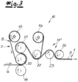
- Fig.3 A modified embodiment is shown in which the surface structure is embossed into the strip body 6 by means of a smoothing unit or a calendering unit.
- the embossing device 10 is therefore designed as a smoothing unit or a calendering unit.
- the strip body 6 can initially - as in Fig.1 - produced with the aid of an extruder 9 and run into the embossing device 10 while still hot and plastic and then pass through a smoothing unit or a calender with a smoothing unit lower roller 19, a smoothing unit middle roller 20 and a smoothing unit upper roller 21, each of which is tempered and has a smooth roller surface.
- the embossing gap between the smoothing unit middle roller 20 and the smoothing unit lower roller 19 is preferably adjustable.
- the structural web 7 is guided through this smoothing unit together with the strip body 6.
- the structural web 7 is unwound from an unwinding roller 15 and guided through the smoothing unit with the strip body 6, thus embossing the surface structure into the strip surface.
- the strip provided with the embossed surface structure is guided after leaving the smoothing unit through a cooling device 17', which can consist of several cooling rollers, a first cooling roller 22, a second cooling roller 23 and a third cooling roller 24.
- the structural web 7 is wound up with a winding roller 16, which is arranged downstream of the first cooling roller, so that the structural web is separated from the strip body 6 after the first cooling roller 22.
- the cooling device shown in Fig.3 The embossing device 10 shown is used in an inline process, ie the smoothing unit is arranged directly downstream of an extrusion device 9. In principle, however, it is also possible to install the embossing device 10 after Fig.3 in an offline process according to Fig.2 to use.
- the strip body 6 is manufactured by injection molding.
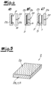
- a structural sheet 7 or a release paper of a predetermined length is inserted into the cavity of an injection molding tool 25 (cf. Fig. 4A ).
- the injection molding tool 25 is closed with the upper tool part 26, which is equipped with the sprue system 27, and the polymer mass is injected into the cavity to form the strip body 6 (cf. Fig. 4B ).
- the surface of the strip is embossed using the structural strip 7.
- the injection molding tool 25 is then opened and the strip 1 with the structured surface is removed, separating it from the structural strip 7 (cf. Fig. 4C ).
- structural track 7 is used as part of the processes according to Figures 1 to 4 always such structural webs can be used which are also used in identical form for the production of the structured plate surfaces 2a, so that the same structural papers 7 are used for the embossing of the plate surfaces 2a and the embossing of the edge strips 1 of the end faces 2b and thus identical or almost identical surface structures are produced.
- Fig.5 shown, because Fig.5 shows a finished, decorative plate 2 with structurally identical embossing of all surface elements.
- the plate according to Fig.5 which is designed as a furniture board, for example, has a wood material core or a wood material board or a structured laminate (CPL or HPL), which is provided with a surface structure in the area of the upper surface 2a and possibly also in the area of the lower (not shown) surface with the help of a structure sheet 7 as a structure provider.
- the edge strips 1 are attached, which are eg made using a process of Figures 1 to 4 and which are consequently provided with an identical strip structure 5.
- structural strips 7 with an identical structure and design are preferably used, which can be cut from one and the same master roll, for example.
Landscapes
- Engineering & Computer Science (AREA)
- Mechanical Engineering (AREA)
- Manufacturing & Machinery (AREA)
- Laminated Bodies (AREA)
- Shaping Of Tube Ends By Bending Or Straightening (AREA)
Claims (16)
- Procédé de fabrication d'une baguette rapportée (1) pour fixation à une plaque décorative (2), par exemple une baguette de bord pour le revêtement de surface étroite d'une plaque de meuble ou similaire, ayant une surface structurée comme face visible,dans lequel un corps de baguette (6) en plastique thermoplastique est fabriqué et, dans la surface de baguette du corps de baguette (6), à l'aide d'au moins un moyen de gravure, une structure de baguette (5) est gravée,caractérisé en ce qu'on utilise comme moyen de gravure une bande structurée (7) qui est pourvue d'une surface gravée structurée (8) et avec laquelle la structure (5) est gravée dans la surface de baguette.
- Procédé selon la revendication 1, caractérisé en ce qu'on utilise comme bande structurée (7) un papier structuré.
- Procédé selon la revendication 1 ou 2, caractérisé en ce qu'est utilisée une bande structurée (7) qui est employée avec une constitution identique et une structure identique également pour la fabrication d'une structure superficielle d'une surface de plaque de la plaque.
- Procédé selon une des revendications 1 à 3, caractérisé en ce que, pour graver la structure de baguette (5), la bande structurée (7) est comprimée sur une distance de l'installation (A) sur une longueur d'au moins 20 cm, de préférence au moins 30 cm, contre la surface de baguette, et ce de préférence sans mouvement relatif entre la bande structurée (7) et la surface de baguette.
- Procédé selon une des revendications 1 à 4, caractérisé en ce que le corps de baguette (6) est fabriqué par extrusion et que la structure (5) est gravée en ligne, c'est-à-dire directement après l'extrusion, dans le corps de baguette (6) se trouvant encore en état plastique chaud.
- Procédé selon une des revendications 1 à 4, caractérisé en ce que le corps de baguette (6) préfabriqué par exemple par extrusion est chauffé et que la structure (5) est gravée dans la surface du corps de baguette (6) réchauffée ultérieurement.
- Procédé selon une des revendications 1 à 6, caractérisé en ce que la structure (15) est gravée en fonctionnement continu dans le corps de baguette en mouvement (6), par exemple après l'extrusion, par le fait que la bande structurée (7) est guidée à la même vitesse que le corps de baguette (6).
- Procédé selon la revendication 7, caractérisé en ce que le corps de baguette (6) est guidé, pour graver la structure (5) en même temps que la bande structurée (7) sur ou autour de plusieurs rouleaux, par exemple des rouleaux de compression (11, 12), des contres-rouleaux (13, 14) et/ou des rouleaux de calandre ou des rouleaux d'unité de lissage (19, 20, 21).
- Procédé selon une des revendications 1 à 4, caractérisé en ce que le corps de baguette (6) est fabriqué par moulage par injection et que la structure (5) est gravée pendant le processus d'injection avec la bande structurée (7) disposée dans l'outil d'injection (25) dans la surface de baguette.
- Procédé selon une des revendications 1 à 9, caractérisé en ce que la bande structurée (7) subit un traitement hydrophobe sur la surface de gravure et/ou sur la face arrière opposée à la surface de gravure, par exemple par une couche de séparation, par exemple un vernissage superficiel et/ou une couche de séparation ou d'agent lubrifiant.
- Procédé selon une des revendications 1 à 10, caractérisé en ce que la surface gravée structurée (8) de la bande structurée (7) est constituée par une couche de vernis structurée.
- Procédé selon une des revendications 1 à 11, caractérisé en ce que la bande structurée (7) présente une épaisseur de 100 pm à 500 pm, de préférence 100 µm à 500 µm, par exemple 120 µm à 250 µm.
- Procédé selon une des revendications 1 à 12, caractérisé en ce que la surface gravée structurée (8) de la bande structurée (7) est présente des proéminences de jusqu'à 200 µm, de préférence jusqu'à 150 µm, et/ou que la surface gravée structurée présente des proéminences d'une hauteur d'au moins 50 µm, par exemple au moins 100 µm.
- Procédé selon une des revendications 1 à 13, caractérisé en ce que la bande structurée (7) est réalisée aussi bien comme élément de structuration que comme élément de brillance, par exemple grâce à une surface gravée satinée.
- Procédé de fabrication d'une plaque décorative (2), en particulier d'une plaque de meuble,dans laquelle un corps de plaque est pourvu au moyen d'au moins un moyen de gravure d'une structure superficielle etétant prévue une baguette rapportée qui est fabriquée par un procédé selon une des revendications 1 à 14 et à laquelle un corps de plaque est fixé, par exemple sur une surface étroite de la plaque,caractérisé en ce que, pour la gravure de la structure superficielle de la plaque et pour la gravure de la structure de baguette (5) de la baguette (1), des bandes structurées (7) ayant la même constitution et une structure identique sont utilisées.
- Procédé selon la revendication 15, caractérisé en ce que les bandes structurées (7) destinées à la surface de plaque (2a) d'une part et à la surface de baguette (2b) d'autre part sont découpées dans le seul et même rouleau mère d'une bande structurée (7).
Applications Claiming Priority (2)
| Application Number | Priority Date | Filing Date | Title |
|---|---|---|---|
| DE102020120395.0A DE102020120395A1 (de) | 2020-08-03 | 2020-08-03 | Verfahren zum Herstellen einer Anbauleiste |
| PCT/EP2021/065974 WO2022028758A1 (fr) | 2020-08-03 | 2021-06-14 | Procédé de production d'une bande de fixation |
Publications (3)
| Publication Number | Publication Date |
|---|---|
| EP4146453A1 EP4146453A1 (fr) | 2023-03-15 |
| EP4146453B1 true EP4146453B1 (fr) | 2024-09-18 |
| EP4146453C0 EP4146453C0 (fr) | 2024-09-18 |
Family
ID=76695694
Family Applications (1)
| Application Number | Title | Priority Date | Filing Date |
|---|---|---|---|
| EP21735859.7A Active EP4146453B1 (fr) | 2020-08-03 | 2021-06-14 | Procédé de production d'une bande de fixation |
Country Status (5)
| Country | Link |
|---|---|
| EP (1) | EP4146453B1 (fr) |
| BR (1) | BR112023001914A2 (fr) |
| DE (1) | DE102020120395A1 (fr) |
| MX (1) | MX2023001326A (fr) |
| WO (1) | WO2022028758A1 (fr) |
Family Cites Families (9)
| Publication number | Priority date | Publication date | Assignee | Title |
|---|---|---|---|---|
| DE2111141A1 (de) | 1971-03-09 | 1972-09-14 | Westag & Getalit Ag | Schichtpressstoffplatte mit witterungsbestaendiger Oberflaechenschicht und Verfahren zu ihrer Herstellung |
| US3666516A (en) | 1971-10-12 | 1972-05-30 | Richard E Dunning | Hot stamp tape |
| WO2008061765A1 (fr) | 2006-11-23 | 2008-05-29 | S.D. Warren Company, D/B/A | Procédé d'impression directe de plaques en matériau à base de bois |
| US9296146B1 (en) * | 2012-03-09 | 2016-03-29 | Rambus Delaware Llc | Extrusion-to-sheet production line and method |
| JP5779550B2 (ja) | 2012-06-21 | 2015-09-16 | 株式会社日立産機システム | 微細構造転写装置 |
| PL2818292T3 (pl) | 2013-06-25 | 2018-09-28 | Faurecia Innenraum Systeme Gmbh | Sposób formowania elementu wykończenia mającego warstwę materiału drzewnego i wygrawerowany wzór |
| NL2016215B1 (en) | 2016-02-03 | 2017-08-11 | Trespa Int Bv | A method for manufacturing a registered embossed decorative panel |
| PL3415316T3 (pl) | 2017-06-13 | 2020-10-05 | Hymmen GmbH Maschinen- und Anlagenbau | Sposób i urządzenie do wytwarzania strukturyzowanej powierzchni |
| CN107263852A (zh) * | 2017-06-27 | 2017-10-20 | 东莞市华立实业股份有限公司 | 一种平板封边条压纹机 |
-
2020
- 2020-08-03 DE DE102020120395.0A patent/DE102020120395A1/de not_active Withdrawn
-
2021
- 2021-06-14 WO PCT/EP2021/065974 patent/WO2022028758A1/fr not_active Ceased
- 2021-06-14 BR BR112023001914A patent/BR112023001914A2/pt unknown
- 2021-06-14 EP EP21735859.7A patent/EP4146453B1/fr active Active
- 2021-06-14 MX MX2023001326A patent/MX2023001326A/es unknown
Also Published As
| Publication number | Publication date |
|---|---|
| DE102020120395A1 (de) | 2022-02-03 |
| EP4146453C0 (fr) | 2024-09-18 |
| WO2022028758A1 (fr) | 2022-02-10 |
| EP4146453A1 (fr) | 2023-03-15 |
| BR112023001914A2 (pt) | 2023-03-07 |
| MX2023001326A (es) | 2023-03-06 |
Similar Documents
| Publication | Publication Date | Title |
|---|---|---|
| DE4446255C2 (de) | Dekorationsfolie zum Dekorieren von dreidimensionalen Substratoberflächen | |
| EP2065217B1 (fr) | Dispositif et procédé destinés à l'échantillonnage d'une pièce à usiner utilisant des matériaux en bandes | |
| DE102005006084B4 (de) | Verfahren und Vorrichtung zum Erzeugen einer strukturierten Lackoberfläche sowie Paneel mit einer strukturierten Lackoberfläche | |
| EP3181372B1 (fr) | Procédé de transformation d'une plaque en bois | |
| DE3010060C2 (fr) | ||
| EP2223800B1 (fr) | Produit décoratif, procédé de fabrication d'un produit décoratif et utilisation d'un produit décoratif pour fabriquer une surface de support décorée | |
| EP2315668A1 (fr) | Procédé de laminage de surfaces à haut brillant | |
| WO2017198550A1 (fr) | Procédé de fabrication d'un profilé de chant et partie de meuble | |
| EP1984191B1 (fr) | Procede de fabrication d'une languette profilee | |
| WO2012034548A1 (fr) | Élément de construction intérieur destiné au revêtement et procédé de fabrication d'un élément de construction intérieur | |
| EP4146453B1 (fr) | Procédé de production d'une bande de fixation | |
| DE10133813A1 (de) | Verfahren zur Herstellung von Teilen, teilweise bestehend aus Kunststoffschaum | |
| EP1700714B1 (fr) | Procédé et dispositif de fabrication des corps profilés décorés d'un élément flexible | |
| DE102009041928B4 (de) | Verfahren zur Oberflächenglättung und Vorrichtung zur Flächenkaschierung | |
| DE202006002835U1 (de) | Fahrzeuginnenraumdekorteil | |
| DD206102B1 (de) | Verfahren zur herstellung von formteilen aus lagerwerkstoffen | |
| DE102007003746B4 (de) | Verfahren und Vorrichtung zum beidseitigen Beschichten einer Platte | |
| EP3999358B1 (fr) | Procédé de fabrication d'une structure sur une surface | |
| EP2065186A1 (fr) | Procédé destiné à la fabrication d'un panneau de construction léger et dispositif d'exécution du procédé | |
| EP1965973A1 (fr) | Procede de fabrication de feuilles multicolores | |
| DE102012102996B4 (de) | Verfahren zur Strukturierung der Oberfläche eines Dekorformteils aus Kunststofffolie | |
| DE19916565A1 (de) | Verfahren und Vorrichtung zum dreidimensionalen Kaschieren von plattenförmigen Werkstücken | |
| DE102012111809B4 (de) | Dekoratives Oberflächenmaterial für Fußböden und Möbel sowie Verfahren zu dessen Herstellung | |
| EP4729304A1 (fr) | Procédé de fabrication d'un composant et utilisation d'un film dans un procédé de fabrication d'un composant pour la réduction d'impuretés | |
| DE102014104355B4 (de) | Verfahren zur Herstellung einer aus einem Holzwerkstoff bestehenden, mit einer Musterung versehenen Türen-Deckplatte sowie eine nach diesem Verfahren hergestellte Türen-Deckplatte |
Legal Events
| Date | Code | Title | Description |
|---|---|---|---|
| STAA | Information on the status of an ep patent application or granted ep patent |
Free format text: STATUS: UNKNOWN |
|
| STAA | Information on the status of an ep patent application or granted ep patent |
Free format text: STATUS: THE INTERNATIONAL PUBLICATION HAS BEEN MADE |
|
| PUAI | Public reference made under article 153(3) epc to a published international application that has entered the european phase |
Free format text: ORIGINAL CODE: 0009012 |
|
| STAA | Information on the status of an ep patent application or granted ep patent |
Free format text: STATUS: REQUEST FOR EXAMINATION WAS MADE |
|
| 17P | Request for examination filed |
Effective date: 20221207 |
|
| AK | Designated contracting states |
Kind code of ref document: A1 Designated state(s): AL AT BE BG CH CY CZ DE DK EE ES FI FR GB GR HR HU IE IS IT LI LT LU LV MC MK MT NL NO PL PT RO RS SE SI SK SM TR |
|
| DAV | Request for validation of the european patent (deleted) | ||
| DAX | Request for extension of the european patent (deleted) | ||
| GRAP | Despatch of communication of intention to grant a patent |
Free format text: ORIGINAL CODE: EPIDOSNIGR1 |
|
| STAA | Information on the status of an ep patent application or granted ep patent |
Free format text: STATUS: GRANT OF PATENT IS INTENDED |
|
| GRAS | Grant fee paid |
Free format text: ORIGINAL CODE: EPIDOSNIGR3 |
|
| INTG | Intention to grant announced |
Effective date: 20240625 |
|
| GRAA | (expected) grant |
Free format text: ORIGINAL CODE: 0009210 |
|
| STAA | Information on the status of an ep patent application or granted ep patent |
Free format text: STATUS: THE PATENT HAS BEEN GRANTED |
|
| AK | Designated contracting states |
Kind code of ref document: B1 Designated state(s): AL AT BE BG CH CY CZ DE DK EE ES FI FR GB GR HR HU IE IS IT LI LT LU LV MC MK MT NL NO PL PT RO RS SE SI SK SM TR |
|
| REG | Reference to a national code |
Ref country code: GB Ref legal event code: FG4D Free format text: NOT ENGLISH |
|
| REG | Reference to a national code |
Ref country code: CH Ref legal event code: EP |
|
| REG | Reference to a national code |
Ref country code: IE Ref legal event code: FG4D Free format text: LANGUAGE OF EP DOCUMENT: GERMAN |
|
| REG | Reference to a national code |
Ref country code: DE Ref legal event code: R096 Ref document number: 502021005191 Country of ref document: DE |
|
| U01 | Request for unitary effect filed |
Effective date: 20241004 |
|
| U07 | Unitary effect registered |
Designated state(s): AT BE BG DE DK EE FI FR IT LT LU LV MT NL PT RO SE SI Effective date: 20241025 |
|
| PG25 | Lapsed in a contracting state [announced via postgrant information from national office to epo] |
Ref country code: NO Free format text: LAPSE BECAUSE OF FAILURE TO SUBMIT A TRANSLATION OF THE DESCRIPTION OR TO PAY THE FEE WITHIN THE PRESCRIBED TIME-LIMIT Effective date: 20241218 |
|
| PG25 | Lapsed in a contracting state [announced via postgrant information from national office to epo] |
Ref country code: GR Free format text: LAPSE BECAUSE OF FAILURE TO SUBMIT A TRANSLATION OF THE DESCRIPTION OR TO PAY THE FEE WITHIN THE PRESCRIBED TIME-LIMIT Effective date: 20241219 |
|
| PG25 | Lapsed in a contracting state [announced via postgrant information from national office to epo] |
Ref country code: HR Free format text: LAPSE BECAUSE OF FAILURE TO SUBMIT A TRANSLATION OF THE DESCRIPTION OR TO PAY THE FEE WITHIN THE PRESCRIBED TIME-LIMIT Effective date: 20240918 |
|
| PG25 | Lapsed in a contracting state [announced via postgrant information from national office to epo] |
Ref country code: RS Free format text: LAPSE BECAUSE OF FAILURE TO SUBMIT A TRANSLATION OF THE DESCRIPTION OR TO PAY THE FEE WITHIN THE PRESCRIBED TIME-LIMIT Effective date: 20241218 |
|
| PG25 | Lapsed in a contracting state [announced via postgrant information from national office to epo] |
Ref country code: RS Free format text: LAPSE BECAUSE OF FAILURE TO SUBMIT A TRANSLATION OF THE DESCRIPTION OR TO PAY THE FEE WITHIN THE PRESCRIBED TIME-LIMIT Effective date: 20241218 Ref country code: NO Free format text: LAPSE BECAUSE OF FAILURE TO SUBMIT A TRANSLATION OF THE DESCRIPTION OR TO PAY THE FEE WITHIN THE PRESCRIBED TIME-LIMIT Effective date: 20241218 Ref country code: HR Free format text: LAPSE BECAUSE OF FAILURE TO SUBMIT A TRANSLATION OF THE DESCRIPTION OR TO PAY THE FEE WITHIN THE PRESCRIBED TIME-LIMIT Effective date: 20240918 Ref country code: GR Free format text: LAPSE BECAUSE OF FAILURE TO SUBMIT A TRANSLATION OF THE DESCRIPTION OR TO PAY THE FEE WITHIN THE PRESCRIBED TIME-LIMIT Effective date: 20241219 |
|
| PG25 | Lapsed in a contracting state [announced via postgrant information from national office to epo] |
Ref country code: IS Free format text: LAPSE BECAUSE OF FAILURE TO SUBMIT A TRANSLATION OF THE DESCRIPTION OR TO PAY THE FEE WITHIN THE PRESCRIBED TIME-LIMIT Effective date: 20250118 |
|
| PG25 | Lapsed in a contracting state [announced via postgrant information from national office to epo] |
Ref country code: SM Free format text: LAPSE BECAUSE OF FAILURE TO SUBMIT A TRANSLATION OF THE DESCRIPTION OR TO PAY THE FEE WITHIN THE PRESCRIBED TIME-LIMIT Effective date: 20240918 |
|
| PG25 | Lapsed in a contracting state [announced via postgrant information from national office to epo] |
Ref country code: ES Free format text: LAPSE BECAUSE OF FAILURE TO SUBMIT A TRANSLATION OF THE DESCRIPTION OR TO PAY THE FEE WITHIN THE PRESCRIBED TIME-LIMIT Effective date: 20240918 |
|
| PG25 | Lapsed in a contracting state [announced via postgrant information from national office to epo] |
Ref country code: CZ Free format text: LAPSE BECAUSE OF FAILURE TO SUBMIT A TRANSLATION OF THE DESCRIPTION OR TO PAY THE FEE WITHIN THE PRESCRIBED TIME-LIMIT Effective date: 20240918 Ref country code: PL Free format text: LAPSE BECAUSE OF FAILURE TO SUBMIT A TRANSLATION OF THE DESCRIPTION OR TO PAY THE FEE WITHIN THE PRESCRIBED TIME-LIMIT Effective date: 20240918 |
|
| PG25 | Lapsed in a contracting state [announced via postgrant information from national office to epo] |
Ref country code: SK Free format text: LAPSE BECAUSE OF FAILURE TO SUBMIT A TRANSLATION OF THE DESCRIPTION OR TO PAY THE FEE WITHIN THE PRESCRIBED TIME-LIMIT Effective date: 20240918 |
|
| U20 | Renewal fee for the european patent with unitary effect paid |
Year of fee payment: 5 Effective date: 20250515 |
|
| PLBE | No opposition filed within time limit |
Free format text: ORIGINAL CODE: 0009261 |
|
| STAA | Information on the status of an ep patent application or granted ep patent |
Free format text: STATUS: NO OPPOSITION FILED WITHIN TIME LIMIT |
|
| 26N | No opposition filed |
Effective date: 20250619 |
|
| REG | Reference to a national code |
Ref country code: CH Ref legal event code: H13 Free format text: ST27 STATUS EVENT CODE: U-0-0-H10-H13 (AS PROVIDED BY THE NATIONAL OFFICE) Effective date: 20260127 |
|
| PG25 | Lapsed in a contracting state [announced via postgrant information from national office to epo] |
Ref country code: MC Free format text: LAPSE BECAUSE OF FAILURE TO SUBMIT A TRANSLATION OF THE DESCRIPTION OR TO PAY THE FEE WITHIN THE PRESCRIBED TIME-LIMIT Effective date: 20240918 |
|
| GBPC | Gb: european patent ceased through non-payment of renewal fee |
Effective date: 20250614 |
|
| PG25 | Lapsed in a contracting state [announced via postgrant information from national office to epo] |
Ref country code: GB Free format text: LAPSE BECAUSE OF NON-PAYMENT OF DUE FEES Effective date: 20250614 |
|
| PG25 | Lapsed in a contracting state [announced via postgrant information from national office to epo] |
Ref country code: IE Free format text: LAPSE BECAUSE OF NON-PAYMENT OF DUE FEES Effective date: 20250614 |
|
| PG25 | Lapsed in a contracting state [announced via postgrant information from national office to epo] |
Ref country code: CH Free format text: LAPSE BECAUSE OF NON-PAYMENT OF DUE FEES Effective date: 20250630 |