EP4147155B1 - System zur identifizierung, lokalisierung und lagerung von histologiekassetten und -objektträgern - Google Patents
System zur identifizierung, lokalisierung und lagerung von histologiekassetten und -objektträgern Download PDFInfo
- Publication number
- EP4147155B1 EP4147155B1 EP21727556.9A EP21727556A EP4147155B1 EP 4147155 B1 EP4147155 B1 EP 4147155B1 EP 21727556 A EP21727556 A EP 21727556A EP 4147155 B1 EP4147155 B1 EP 4147155B1
- Authority
- EP
- European Patent Office
- Prior art keywords
- rfid
- demultiplexer
- tray
- antenna
- antennas
- Prior art date
- Legal status (The legal status is an assumption and is not a legal conclusion. Google has not performed a legal analysis and makes no representation as to the accuracy of the status listed.)
- Active
Links
Images


Classifications
-
- G—PHYSICS
- G06—COMPUTING OR CALCULATING; COUNTING
- G06K—GRAPHICAL DATA READING; PRESENTATION OF DATA; RECORD CARRIERS; HANDLING RECORD CARRIERS
- G06K7/00—Methods or arrangements for sensing record carriers, e.g. for reading patterns
- G06K7/10—Methods or arrangements for sensing record carriers, e.g. for reading patterns by electromagnetic radiation, e.g. optical sensing; by corpuscular radiation
-
- G—PHYSICS
- G06—COMPUTING OR CALCULATING; COUNTING
- G06K—GRAPHICAL DATA READING; PRESENTATION OF DATA; RECORD CARRIERS; HANDLING RECORD CARRIERS
- G06K19/00—Record carriers for use with machines and with at least a part designed to carry digital markings
- G06K19/06—Record carriers for use with machines and with at least a part designed to carry digital markings characterised by the kind of the digital marking, e.g. shape, nature, code
- G06K19/067—Record carriers with conductive marks, printed circuits or semiconductor circuit elements, e.g. credit or identity cards also with resonating or responding marks without active components
- G06K19/07—Record carriers with conductive marks, printed circuits or semiconductor circuit elements, e.g. credit or identity cards also with resonating or responding marks without active components with integrated circuit chips
- G06K19/077—Constructional details, e.g. mounting of circuits in the carrier
- G06K19/07749—Constructional details, e.g. mounting of circuits in the carrier the record carrier being capable of non-contact communication, e.g. constructional details of the antenna of a non-contact smart card
- G06K19/07758—Constructional details, e.g. mounting of circuits in the carrier the record carrier being capable of non-contact communication, e.g. constructional details of the antenna of a non-contact smart card arrangements for adhering the record carrier to further objects or living beings, functioning as an identification tag
-
- B—PERFORMING OPERATIONS; TRANSPORTING
- B01—PHYSICAL OR CHEMICAL PROCESSES OR APPARATUS IN GENERAL
- B01L—CHEMICAL OR PHYSICAL LABORATORY APPARATUS FOR GENERAL USE
- B01L3/00—Containers or dishes for laboratory use, e.g. laboratory glassware; Droppers
- B01L3/54—Labware with identification means
- B01L3/545—Labware with identification means for laboratory containers
-
- B—PERFORMING OPERATIONS; TRANSPORTING
- B01—PHYSICAL OR CHEMICAL PROCESSES OR APPARATUS IN GENERAL
- B01L—CHEMICAL OR PHYSICAL LABORATORY APPARATUS FOR GENERAL USE
- B01L9/00—Supporting devices; Holding devices
- B01L9/52—Supports specially adapted for flat sample carriers, e.g. for plates, slides, chips
- B01L9/523—Supports specially adapted for flat sample carriers, e.g. for plates, slides, chips for multisample carriers, e.g. used for microtitration plates
-
- G—PHYSICS
- G06—COMPUTING OR CALCULATING; COUNTING
- G06K—GRAPHICAL DATA READING; PRESENTATION OF DATA; RECORD CARRIERS; HANDLING RECORD CARRIERS
- G06K19/00—Record carriers for use with machines and with at least a part designed to carry digital markings
- G06K19/06—Record carriers for use with machines and with at least a part designed to carry digital markings characterised by the kind of the digital marking, e.g. shape, nature, code
- G06K19/067—Record carriers with conductive marks, printed circuits or semiconductor circuit elements, e.g. credit or identity cards also with resonating or responding marks without active components
- G06K19/07—Record carriers with conductive marks, printed circuits or semiconductor circuit elements, e.g. credit or identity cards also with resonating or responding marks without active components with integrated circuit chips
- G06K19/077—Constructional details, e.g. mounting of circuits in the carrier
- G06K19/07701—Constructional details, e.g. mounting of circuits in the carrier the record carrier comprising an interface suitable for human interaction
- G06K19/07713—Constructional details, e.g. mounting of circuits in the carrier the record carrier comprising an interface suitable for human interaction the interface, upon reception of an interrogation signal, being capable of signaling to indicate its position to a user or a detection device
-
- G—PHYSICS
- G06—COMPUTING OR CALCULATING; COUNTING
- G06K—GRAPHICAL DATA READING; PRESENTATION OF DATA; RECORD CARRIERS; HANDLING RECORD CARRIERS
- G06K7/00—Methods or arrangements for sensing record carriers, e.g. for reading patterns
- G06K7/10—Methods or arrangements for sensing record carriers, e.g. for reading patterns by electromagnetic radiation, e.g. optical sensing; by corpuscular radiation
- G06K7/10009—Methods or arrangements for sensing record carriers, e.g. for reading patterns by electromagnetic radiation, e.g. optical sensing; by corpuscular radiation sensing by radiation using wavelengths larger than 0.1 mm, e.g. radio-waves or microwaves
- G06K7/10316—Methods or arrangements for sensing record carriers, e.g. for reading patterns by electromagnetic radiation, e.g. optical sensing; by corpuscular radiation sensing by radiation using wavelengths larger than 0.1 mm, e.g. radio-waves or microwaves using at least one antenna particularly designed for interrogating the wireless record carriers
- G06K7/10356—Methods or arrangements for sensing record carriers, e.g. for reading patterns by electromagnetic radiation, e.g. optical sensing; by corpuscular radiation sensing by radiation using wavelengths larger than 0.1 mm, e.g. radio-waves or microwaves using at least one antenna particularly designed for interrogating the wireless record carriers using a plurality of antennas, e.g. configurations including means to resolve interference between the plurality of antennas
-
- B—PERFORMING OPERATIONS; TRANSPORTING
- B01—PHYSICAL OR CHEMICAL PROCESSES OR APPARATUS IN GENERAL
- B01L—CHEMICAL OR PHYSICAL LABORATORY APPARATUS FOR GENERAL USE
- B01L1/00—Enclosures; Chambers
- B01L1/04—Dust-free rooms or enclosures
-
- B—PERFORMING OPERATIONS; TRANSPORTING
- B01—PHYSICAL OR CHEMICAL PROCESSES OR APPARATUS IN GENERAL
- B01L—CHEMICAL OR PHYSICAL LABORATORY APPARATUS FOR GENERAL USE
- B01L2300/00—Additional constructional details
- B01L2300/02—Identification, exchange or storage of information
- B01L2300/021—Identification, e.g. bar codes
- B01L2300/022—Transponder chips
Definitions
- the present invention relates to the field of the storage of biological samples, in particular histology samples, more in particular biological tissue samples.
- the invention relates to a system which allows identifying, localize and trace the supports, in particular histology cassettes or slides, for the samples and therefore the samples themselves.
- tissue samples may be used for histological analyses.
- the tissue samples undergo fixation, washing and dehydration procedures. They are then embedded in paraffin to preserve the chemical properties of the sample. Thereby, the samples are preserved so as to be processed in the future, even after years.
- the samples are placed in cassettes of a standard shape and size, typically made of acetal resin.
- cassettes are also known as histology cassettes or tissue embedding cassettes.
- the tissue samples in paraffin are cut with the microtome so as to obtain sections thereof of a few microns, which are penetrable by light and therefore observable under the microscope following staining with stains or with reagents adapted to highlight the presence of molecular markers and verify the integrity of the tissue structures.
- the cut sections are fixed on laboratory slides.
- the procedure is therefore slow and subject to human error.
- each sample and the traceability (tracing) thereof are a set of critical operations extremely important in the healthcare practice, whose automation would be advantageous, with a view to optimize processes and computerize clinical risk management.
- Document JP2005339507A describes a system wherein laboratory test tubes are provided with a Radio Frequency IDentification tag (RFID), and wherein a reader provided with antennas for the RFID tags of the tubes is provided.
- RFID Radio Frequency IDentification tag
- JP2005339507A is not suitable for processing a very large number of biological samples.
- JP2005339507A is not energy efficient, is expensive to make and has many components subject to breakage.
- each antenna is disadvantageously provided with a respective impedance matching network (each impedance matching network comprising a capacitor and other elements) which is arranged between the switch and the body of the antenna.
- the number of impedance matching networks is equal to the number of antennas.
- an (active) antenna is brought to the same resonant frequency, called the first resonant frequency, as the RFID tag, while all the other antennas are brought to a second resonant frequency, which is different from said first resonant frequency.
- all the other antennas are at the second resonant frequency, except one antenna which is at the first resonant frequency equal to the resonant frequency of the RFID tag.
- the RFID tag should only communicate with the antenna which is at the same resonant frequency thereof.
- the present invention achieves at least one of such objects and other objects which will become apparent in light of the present description, by means of a system according to claim 1
- Ahistobgy cassette provided with an RFID tag is disclosed in present description.
- a tray configured to hold histology cassettes or slides provided with an RFID tag is disclosed in the present description.
- the invention also relates to a cabinet according to claim 15.
- the system allows identifying and localizing samples even in the presence of debris, for example paraffin, which may possibly hide numbered labels, for example on the sample support or tray.
- debris for example paraffin
- the system allows identifying and localizing samples even in the presence of debris, for example paraffin, which may possibly hide numbered labels, for example on the sample support or tray.
- the system allows identifying and localizing samples very quickly and reliably inside trays.
- the identification and localization of about 250 samples in a tray can be performed in about 20 seconds.
- the system does not require an extremely precise positioning of the support in the respective seat of the tray.
- the system does not require moving mechanical parts to identify and localize the samples.
- the RFID reading occurs sequentially on different RFID antennas, allowing the system, in addition to perform normal identification, to know the position of an RFID tag, and therefore of a biological sample, in particular an histology sample, on the tray.
- the system offers the possibility of querying the single RFID antennas, arranged, in particular, according to a dense matrix, without interfering with the adjacent antennas.
- said one or more demultiplexers capable of sequentially activating a unique transmission line for each RFID antenna, in particular, so that only one antenna at a time is electrically connected to the RFID interrogator, while the other RFID antennas are electrically disconnected from the RFID interrogator. Reading errors and interference between antennas are therefore drastically reduced.
- the system is capable of reliably reading the RFID tags, both of the supports and of the tray, even in the event of: poor lighting conditions; presence of paraffin or other substances on the sample support surface and/or on the tray; imperfect positioning of the sample support; wear or corrosion of the surfaces involved in the reading process.
- the RFID antennas are, in particular, designed to have a limited reading volume.
- the RFID antennas are capable of reading the data contained in an RFID tag, in particular, the identification serial number of the tag. Every single RFID antenna may be queried by the RFID reader by using one or more demultiplexers.
- the RFID interrogator may be connected to the input, in particular to the single input, of the demultiplexer and the RFID antennas may be connected to the outputs of the demultiplexer.
- each tray is provided with a respective RFID tag.
- an IT system for example a computer, which is capable of storing the data received.
- each tray is provided with a respective RFID tag.
- An advantage of this feature is given by the fact that the tray can be identified, for example, inside a tray-holder cabinet.
- the cabinet is also provided with an RFID tag.
- a plurality of cabinets may be provided, each provided with a respective RFID tag.
- the system of the invention is the optimal solution for tracing histology cassettes and slides for histology samples, by means of the recognition of the ID, and for accessing the data relating to the patient (without however managing the personal data thereof, but operating by means of an association with the relevant case ID).
- Any information managed by the system database can be made available to all other applications and equipment involved in the process.
- cassette and slide management in particular, in terms of position within a single tray and trays, for example, within a single cabinet, as well as within the hospital, both during the exchange between hospitals and during conservation.
- the system of the invention allows the unique identification and the traceability of the samples throughout the cycle, from collection to processing, to storage.
- biological samples collected in operating theaters and specialist clinics may be accompanied by a large set of information to be sent to the pathological anatomy department.
- the pathological anatomy report is returned to the doctor treating the patient and the sample is archived.
- the ID of the single sample is associated with the histopathological data of the patient. Since the samples originate from a variety of different sources, it is necessary for the information to be correctly associated with the samples, so as to reduce clinical risk.
- the pathological anatomy laboratory must be capable of tracing each step of the process in detail, ensuring that it is completed in the correct sequence.
- the system allows tracing histology cassettes and tissue slides with the aid of RFID technology.
- the two-dimensional code is printed on the histology cassette by means of particular printers which may be thermal transfer or laser printers. In both cases, the printer prints directly onto the plastic of the cassette. Slides may be coded in a similar manner. The scanner simply reads the code that the laser or thermal transfer printer has printed directly on the cassette.
- the code is unreadable by the scanner, in particular because it has been printed ineffectively and/or due to the presence of paraffin debris.
- the code is unreadable by the scanner because it is poorly printed, sometimes half-printed.
- the code is unreadable by the scanner due to uncleaned paraffin debris on the cassette, in particular, on the side of the printed part, therefore, although being visible to the human eye, in the photo taken by the scanner, the reflection effect of the paraffin prevents the reading of the code.
- the reading system allows, after having associated the case ID, which was generated at the acceptance of the operating piece, with the RFID tag associated with the cassette or slide, to simultaneously archive a multitude of cassettes or slides (and, therefore, of samples), tracing the position thereof and associating them with a tray and preferably with the cabinet in which they are stored.
- the invention therefore allows facilitating and speeding up the routine work of the technical staff and the pathologists, greatly reducing the possibility of human error.
- Another laboratory process for the analysis of biological samples is the subdivision of a single sample into several sub-samples. By means of the system of the invention, it is possible to keep track of the origin of the generated sub-samples, which, for example, are arranged on slides.
- the system allows reading, in an efficient and reliable manner, information relating to histology cassettes or slides where tissue samples embedded in paraffin are arranged, and information relating to the tray containing the histology cassettes or the slides.
- information relating to the tray containing the histology cassettes or the slides is arranged, and information relating to the tray containing the histology cassettes or the slides.
- the system may be equipped with a simple and intuitive user interface. Further features and advantages of the invention will become more apparent in light of the detailed description of non-exclusive embodiments.
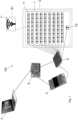
- the system 100 is used in particular for storing, identifying and localizing biological samples, in particular, histology samples.
- the system 100 is used for storing, identifying and localizing histology cassettes 20 containing tissue samples embedded in paraffin or slides 21 on which tissue samples embedded in paraffin are arranged.
- the system 100 comprises
- the histology cassettes 20 are, in particular, cassettes for histological inclusions and are also referred to as tissue embedding cassettes.
- the histology cassettes 20 may also be referred to as cassettes 20.
- each cassette 20 has a conventional size and/or a conventional shape.
- each cassette 20 has a width from about 28 to 53 mm; a length from about 48 to 71 mm, and a thickness from about 6 to 19 mm.
- a cassette 20 may have a size of about 28.5mm ⁇ 41mm ⁇ 6mm, or about 52.5mm ⁇ 75mm ⁇ 18.3mm, or about 52.3mm ⁇ 75mm ⁇ 9.5mm.
- each cassette 20 is formed by a perforated grid 29 ( Figure 7 ).
- the slides 21 are in particular histology slides, or laboratory slides.
- Each slide 21 preferably has a size (length x width) of about 76 x 26 mm or 76 x 52 mm.
- each tray 1 has a width from 30 to 50 cm; a length from 20 to 40 cm; and preferably a thickness from 2 to 10 cm.
- the supports are the aforesaid cassettes or slides.
- the seats 11 are arranged according to a matrix or grid.
- the tray 1 may comprise a number of seats 11 from 2 to 4096 or from 100 to 4096 or from 100 to 600 or from 200 to 300.
- the seats 11, in particular, are in positions which facilitate the reading of the RFID tags 201 by means of the RFID antennas 31, 32, 33.
- the seats 11 may, for example, be housings.
- a tray 1 comprises a plurality of internal walls 110 ( Figure 6 ) which are parallel and spaced apart, provided with a plurality of grooves 111; and wherein each pair of grooves 111 facing each other defines at least part of a seat 11 for a support 20, 21, for example, for a histology cassette 20.
- Each support 20, 21 is configured to be inserted in a pair of grooves 111 facing each other.
- the supports 20, 21 may be positioned at, in particular inside, the respective seat 11 and may be removed from the tray 1.
- the RFID tag 201 is preferably arranged at the part of the support 20, 21 destined to be rested on the tray 1.
- each RFID tag 201 is fixed to a respective support 20, 21.
- each RFID tag 201 is preferably incorporated in a respective cassette 20, in particular in the part of the respective cassette 20 destined to be resting on the tray 1.
- the RFID tag 201 may be incorporated in a wall, for example a base, of the cassette 20.
- the respective RFID tag 201 may be fixed thereto, and the RFID tag 201 may substantially be, for example, a label.
- the tray 1 may, for example, be configured to be arranged inside a cabinet 8, the latter being preferably provided with an own RFID tag 801 thereof.
- the system 100 preferably further comprises an RFID antenna for reading the RFID tag 801 of the cabinet 8.
- the system comprises a plurality of trays 1.
- each tray 1 is provided with a respective RFID tag 101 and the system 100 comprises at least one RFID antenna 10, preferably a single RFID antenna 10, for reading the RFID tag 101 of the tray 1, connected to said RFID interrogator 4 by means of said one or more demultiplexers 5.
- each tray 1 and the respective antenna 10 allow, in particular, identifying a set of supports 20, 21 (and relative samples), in particular, a set of supports 20, 21 to be analyzed.
- an RFID antenna 10 is provided for each component 3 with which the system 100 may be provided.
- the RFID antenna 10 is distinct from the RFID antennas 31, 32, 33.
- the RFID tags 101, 201 are of the passive type, although they may also be of the active type.
- the RFID antennas 31, 32, 33 are used, in particular, for identifying and localizing the supports 20, 21, in particular, the unique RFID tag 201 associated with each support 20, 21.
- the RFID antenna 10 is used, in particular, for identifying and localizing each tray 1, in particular the unique RFID tag 101 associated with each tray 1.
- the RFID antennas 10, 31, 32 33 are Near Field Communication (NFC) antennas.
- NFC Near Field Communication
- the RFID tag 201 of each support 20, 21 is an NFC tag; the RFID tag 101 of each tray 1 is an NFC tag; said at least one RFID interrogator 4 is an NFC interrogator; and said RFID antennas 10, 31, 32, 33 of said plurality of RFID antennas are NFC antennas.
- each RFID antenna 10, 31, 32, 33 has a thickness from 20 ⁇ m to 2 cm, or from 0.4 mm to 3.2 mm.
- each component 3, in addition to the RFID antennas 31, 32, 33 further comprises at least one RFID antenna 10, preferably a single RFID antenna 10, to read the RFID tag 101 of a tray 1, for example, of a respective tray 1.
- each component 3 further comprises one or more demultiplexers 5.
- the component 3 is in particular an electronic component, for example a printed circuit or electronic board.
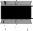
- the component 3 is arranged below the resting surface 18 ( Figures 4 , 5 ), or base surface, of the tray 1.
- the RFID antennas 10, 31, 32, 33 are arranged below the resting surface 18 of the respective tray 1.
- the resting surface 18 of the tray 1 is preferably flat.
- the RFID antennas 10, 31, 32, 33 are arranged on the same surface or on several surfaces, distinct from one another, preferably parallel to one another.
- the surface where the RFID antennas 10, 31, 32, 33 are arranged may be flat or curved.
- the surface where the RFID antennas 10, 31, 32, 33 are arranged is flat, the surface is preferably parallel to the resting surface 18 of the tray 1.
- the RFID antennas 31, 32, 33 are arranged so that the distance, in particular the center-center distance, between the RFID antennas 31, 32, 33 is from 3 to 300 mm or from 5 to 15 mm.
- a structure is provided, for example a cabinet 8 or a trolley, where, in particular, the tray/s 1 and the component/s 3 may be arranged.
- an RFID antenna 31 is provided for each support 20, 21, i.e., an RFID antenna 31 is provided for each seat 11.
- each RFID antenna 31 is provided for each possible position for a support 20, 21. Therefore, there is a bijection (one-to-one correspondence) between each RFID antenna 31 activated by a demultiplexer 5 and the respective support 20, 21 in question.
- the RFID antennas 31 are arranged according to a matrix or grid, in particular, as the seats 11.
- each RFID antenna 31 may be arranged at a respective seat 11 of the tray 1.
- each RFID antenna 31 corresponds to a respective possible position for a support 20, 21.
- each RFID antenna 31-seat 11 pair is crossed by the same respective axis, said axis being, in particular, perpendicular to the resting surface 18 of the tray 1.
- the RFID tag 201 is also preferably crossed by said axis.
- the RFID antenna 10 and the RFID tag 101 of the tray 1 are preferably adapted to be arranged at each other, i.e., substantially aligned with each other.
- the RFID antennas 31 are preferably arranged on the same surface.
- each RFID antenna 31 has a width from 1 to 100 mm or from 4 to 40 mm or from 15 to 35 mm, and/or a length from 1 to 200 mm or from 4 to 40 mm or from 3 to 10 mm.
- a specific support 20, 21 may be identified, for example, the support diagrammatically shown as a star in Figure 2 .
- the RFID tag 101 of the tray 1 is read and, in particular, identified.
- the RFID antennas 32, 33 are provided, which define the rows and columns of a grid, so that at each seat 11 two RFID antennas 32, 33 are provided.
- the RFID antennas 32 define the rows of the grid
- the RFID antennas 33 define the columns of the grid.
- the RFID antennas 32 and the RFID antennas 33 extend at more than one seat 11.
- the intersection areas, i.e., the overlapping areas, between the RFID antennas 32 and the RFID antennas 33 are at a respective seat 11.
- the RFID antennas 32 are arranged on the same surface and the RFID antennas 33 are arranged on the same surface, arranged above or below the surface on which the RFID antennas 32 are arranged.
- the RFID antennas 32 and the RFID antennas 33 may be part of the same component 3 or of two different components 3.
- Each antenna 32 is capable of identifying the row on which a support 20, 21 is positioned, and each antenna 33 is capable of identifying the column on which a support 20, 21 is positioned.
- a specific support 20, 21 may be identified, for example, the support diagrammatically shown as a star in Figure 3 .
- the RFID tag 101 of the tray 1 is read and, in particular, identified.
- the position of the support 20, 21 arranged at a respective seat 11 is identified, in particular, by crossing the obtained detection data.
- each RFID antenna 32, 33 has a width from 5 mm to 1 m or from 10 mm to 500 mm, and/or a length from 5 mm to 1 m or from 10 mm to 500 mm.
- each RFID interrogator 4 is preferably also capable of writing the RFID tags 101, 201.
- more than one RFID interrogator 4 may be provided.
- an RFID interrogator 4 may be provided for each column of a certain number of RFID antennas 31, for example, of ten RFID antennas 31; or, for example, an RFID interrogator 4, adapted to read a part (for example, half) of the RFID antennas 31, 32, 33, and another RFID interrogator 4, adapted to read another part (for example half) of the RFID antennas 31, 32, 33, may be provided.
- the electronic control unit 6 may be connected to a computer 7.
- the computer 7 is in particular provided with or adapted to be connected to an electronic memory, where information relating to the RFID tags 101, 201 may be stored.
- a component 3, the electronic control unit 6, the one or more RFID interrogators 4 and the one or more demultiplexers 5 are part, in particular, of a reading apparatus or system.
- the trays 1 may also be numbered in addition to being provided with a respective RFID tag 101.
- each tray 1 where the samples are arranged is read and the information is saved in a database, for example the memory of the computer 7.
- the tray 1 is then placed, for example, in a cabinet 8.
- the software will indicate the number of the tray 1 and the position of the sample inside the tray 1, and possibly also the number of the cabinet 8.
- the system 100 may be controlled by means of a blockchain.
- the data preferably anonymized, may be recorded in a blockchain.
- the system preferably by means of a big data logic and/or by means of artificial intelligence and/or predictive tools, allows processing data related to the health of the population, and a unique support for research may be provided.
- the anonymous information collected may be made available for research purposes to be used to improve the Precision Medicine Initiative (PMI).
- PMI Precision Medicine Initiative
- each RFID antenna 31, and preferably also each RFID antenna 10 has a Q factor greater than 10, preferably between 10 and 60, preferably between 20 and 40.
- a Q factor greater than 10, i.e., a high Q factor, is particularly advantageous to obtain a limited reading volume and therefore to limit the interference between the antennas 10, 31 as much as possible.
- an example of antenna 31 having a Q factor equal to 29 has the following features.
- the antenna 31 comprises an electrically conductive track, for example made of copper, provided with a plurality of coils.
- the coils are rectangular or substantially rectangular.
- the number of coils is equal to 8.
- the pitch p between the coils is equal to or about equal to 0.5 mm, where the pitch is, in particular, the distance between corresponding points between consecutive coils.
- the maximum width is indicated with reference W M , the maximum width being the width of the outermost coil; the minimum width is indicated with reference W m , the minimum width being the width of the innermost coil; the maximum height is indicated with reference h M , the maximum height being the height of the outermost coil; and the minimum height is indicated with reference h m , the minimum height being the height of the innermost coil.
- the width of the conductive track is indicated with reference s.
- Niwa's formula has been implemented in a Matlab script, by virtue of which it has been possible to design a planar inductor having an inductance > 1 ⁇ H, and a maximum size substantially equal to the size of a cassette 20 increased by 2 mm to accommodate the traces of the coils, and therefore having a maximum width W M of 30 mm and a maximum height h M of 10 mm.
- Figures 9a, 9b, 9c show the result of a finite element numerical simulation (by means of the commercial software package Comsol Multiphysics) based on the particular example of antenna just described.
- the generated magnetic field has been evaluated, in particular, the magnetic induction vector B has been considered.
- the magnetic field generated by the antenna 31 assumes the maximum value in the region of space above the antenna 31 and becomes negligible when moving away from the area delimited by the coils of the inductor (see plane xy). Rising from the antenna plane, at a distance of about 12 mm, the field drastically decays (see plane zy).
- the graph shows that the shape of the field is regular, and it does not show intensity variations or distortions in the reading region.
- the center-center distance between the antennas 31 is equal to about 11 mm.
- antennas 10, 31 having a high Q factor, having features, in particular geometric features, different from those just described.
- each demultiplexer 5, 5', 5", 5" is provided with a single input and a plurality of outputs distinct from one another.
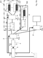
- the antennas 31 for reading the RFID tags 201 of the supports 20, 21 which are connected, in particular directly, to a respective output (distinct from one another) of the same demultiplexer 5, 5" of said one or more demultiplexers 5, 5', 5", 5′′′, have (i.e., are connected to) the same and unique impedance matching network 9, 9';
- said same demultiplexer 5, 5" is the first demultiplexer which is connected upstream of the antennas 31 which are connected to the outputs of the same demultiplexer 5, 5".
- each single antenna 31 does not have a respective impedance matching network thereof, exclusively dedicated to a single antenna 31, by means of which each antenna may be connected to the demultiplexer.
- each antenna may be connected to the demultiplexer.
- no impedance matching networks are present downstream of said same demultiplexer 5, 5".
- the antenna 10 destined for reading, and optionally also for writing, the tag 101 of the tray 1 may include an impedance matching network 9" dedicated thereto, in particular exclusively thereto, so as to provide a particularly reliable reading of the tag 101 of the tray 1.
- the antenna 10 for reading the RFID tag 101 of the tray 1 is connected to an impedance matching network 9", comprising or consisting of one or more resistors 91 and one or more capacitors 92, distinct from the impedance matching network 9, 9' for the antennas 31 for reading the RFID tags 201 of the supports 20, 21.
- the system comprises
- the system further comprises a second group of components 302 which comprises, connected to one another, a second impedance matching network 9", distinct from the first impedance matching network 9' (or from each first impedance matching network 9'), and an antenna 10 for reading the RFID tag 101 of the tray 1; wherein said second impedance matching network 9" comprises or consists of one or more resistors 91 and one or more capacitors 92.
- said second group of components 302 is connected to a second output, distinct from each first output, of the first demultiplexer 5', so that the second impedance matching network 9" is arranged between the first demultiplexer 5' and said antenna 10 for reading the RFID tag 101 of the tray 1.
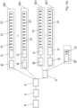
- the system comprises a third demultiplexer 5" connected to an output of the first demultiplexer 5', distinct from each first output; and wherein a respective first group of components 301 is connected to a respective output of the third demultiplexer 5′′′ so that the respective first impedance matching network 9' is arranged between the third demultiplexer 5′′′ and the respective second demultiplexer 5".
- Said second group of components 302 may be connected to a second output, distinct from each first output, of the first demultiplexer 5' ( Figure 10b ), so that the second impedance matching network 9" is arranged between the first demultiplexer 5' and said antenna 10 for reading the RFID tag 101 of the tray 1; or said second group of components 302 may be connected to a respective output of the third demultiplexer 5′′′ ( Figure 10c for example), so that the second impedance matching network 9" is arranged between the third demultiplexer 5′′′ and said antenna 10 for reading the RFID tag 101 of the tray 1.
- a further demultiplexer is connected to the third demultiplexer 5′′′, and one or more first groups of components 301 and/or the second group of components 302, and optionally still a further demultiplexer, and so on, are connected to a respective output of said further demultiplexer.
- each demultiplexer 5" may have twelve outputs distinct from one another. Each antenna 31, in particular each of the twelve antennas 31, is connected to a respective output of the respective demultiplexer 5".
- the demultiplexer 5' has twelve outputs. Also the demultiplexers 5' and 5′′′ may, for example, have twelve outputs.
- a respective first group of components 301 is connected to eleven outputs of the demultiplexer 5', and the demultiplexer 5" (in cascade to the demultiplexer 5') is connected to the twelfth output.
- a respective first group of components 301 is connected to eleven outputs of the demultiplexer 5′′′, and the second group of components 302 is connected to the twelfth output.
- said one or more demultiplexers 5 may preferably comprise two or more demultiplexers connected to one another in cascade, in particular, so that an output of a demultiplexer is connected to the input of the next demultiplexer, so as to define a cascade of demultiplexers.
- one or more first groups of components 301 may be connected to each demultiplexer of the cascade, while a second group of components 302 may be connected to one of the demultiplexers of the cascade, preferably in the manner described above.
- control unit 6 synchronously starts the readings (and/or writings) by means of the RFID interrogator 4 and varies the status of the demultiplexer 5 so as to sequentially query all the antennas 10, 31.
- the control unit 6 configures the demultiplexer 5 (or the demultiplexers) so as to create an exclusive transmission line from the RFID interrogator 4 to the N-th antenna 10, 31.
- the RF signal in the HF band generated by the RFID interrogator 4 reaches the antenna 31 by first crossing the impedance matching network 9 and then the demultiplexer 5 which connects the input thereof with one of the outputs, selected by the electronic control unit 6.
- the antennas 10, 31 consist of an inductor made with one or more metal coils, in particular with an internal area comparable to the size of the tag 101, 201 to be read, for example, having an internal area equal to the area occupied by the corresponding tag 101, 201.
- the antennas 10, 31 are preferably passive, not reconfigurable, and advantageously they do not require dynamic controls and tuning.
- said at least one RFID interrogator 4, said one or more demultiplexers 5, said electronic control unit 6, said impedance matching network 9 (or more impedance matching networks) and said antennas 10, 31 may be integrated on a single PCB.
- the system sequentially connects the RFID interrogator 4 to the antenna 10, 31 to be queried, while keeping all the other antennas disconnected, in particular electrically disconnected.
- the system 100 is configured to read the position of each support 20, 21 in the tray 1 by means of the RFID antenna 31 at said support 20, 21, is configured to read the identification number of the RFID tag of each support 20, 21, and is configured to read the identification number of the RFID tag 101 of the tray 1 in which the support 20, 21 is arranged.
- the system 100 is configured to store said position and said identification numbers in a database.
- the tags 201 of the supports 20, 21, in particular of the histology cassettes 20, are of the on-metal type, per se known.
- each tag 201 is provided with a layer capable of absorbing and/or reflecting the electromagnetic field directed towards the sample embedded in paraffin. Therefore, the tag 201 may substantially communicate only in the direction of the RFID interrogator 4, while the sample is shielded from any electromagnetic fields emitted by the antenna 31 or by the tag 201 itself.
Landscapes
- Engineering & Computer Science (AREA)
- Physics & Mathematics (AREA)
- Health & Medical Sciences (AREA)
- Theoretical Computer Science (AREA)
- General Physics & Mathematics (AREA)
- Toxicology (AREA)
- Chemical & Material Sciences (AREA)
- General Health & Medical Sciences (AREA)
- Electromagnetism (AREA)
- Chemical Kinetics & Catalysis (AREA)
- Artificial Intelligence (AREA)
- Computer Vision & Pattern Recognition (AREA)
- Clinical Laboratory Science (AREA)
- Computer Hardware Design (AREA)
- Microelectronics & Electronic Packaging (AREA)
- Computer Networks & Wireless Communication (AREA)
- Analytical Chemistry (AREA)
- Sampling And Sample Adjustment (AREA)
- Automatic Analysis And Handling Materials Therefor (AREA)
- Investigating Or Analysing Biological Materials (AREA)
Claims (15)
- System (100) zur Lagerung, Identifizierung und Lokalisierung von Trägern (20, 21) für in Paraffin eingebettete Gewebeproben, wobei das System umfasst- eine Vielzahl von Trägern (20, 21), von denen jeder mit einem jeweiligen RFID-Etikett (201) versehen ist,wobei die Träger (20, 21) jeweilseine Histologiekassette (20), die zum Enthalten einer in Paraffin eingebetteten Gewebeprobe ausgelegt ist, oder ein Objektträger (21) sind;- eine Vielzahl von Schalen (1),von denen jede Schale (1) mit einem jeweiligen RFID-Etikett (101) versehen ist und zum Enthalten einer Vielzahl der Träger (20, 21) ausgelegt ist,wobei jede Schale (1) mit einer Vielzahl von Sitzen (11) versehen ist, wobei jeder Sitz (11) zur Aufnahme eines jeweiligen Trägers (20, 21) ausgelegt ist und jeder Träger (20 ,21) dazu geeignet ist, in einem jeweiligen Sitz (11) angeordnet zu werden;- mindestens eine Komponente (3), die mit einer Vielzahl von RFID-Antennen (10, 31) versehen ist, wobei die Vielzahl von RFID-Antennen (10, 31) eine RFID-Antenne (10) zum Lesen des RFID-Etiketts (101) einer Schale (1) der Vielzahl von Schalen und RFID-Antennen (31) zum Lesen des RFID-Etiketts (201) der Träger (20, 21) umfasst;- mindestens eine RFID-Abfragevorrichtung (4);
dadurch gekennzeichnet, dass das System (100) ferner umfasst- einen oder mehrere Demultiplexer (5, 5', 5", 5‴) mittels der die RFID-Abfragevorrichtung (4) mit jeder RFID-Antenne (10, 31) der Vielzahl von RFID-Antennen (10, 31) verbunden werden kann, wobei der eine oder die mehreren Demultiplexer (5, 5', 5", 5‴) dazu ausgelegt sind, nacheinander eine eindeutige Signalübertragungsleitung für jede RFID-Antenne (10 ,31) der Vielzahl von RFID-Antennen (10, 31) zu aktivieren;- eine elektronische Steuereinheit (6), die dazu ausgelegt ist, den einen oder die mehreren Demultiplexer (5, 5', 5", 5"') und die mindestens eine RFID-Abfragevorrichtung (4) miteinander zu synchronisieren, um die RFID-Etiketten (210) der Träger (20, 21) und das RFID-Etikett (101) einer Schale (1) der Vielzahl von Schalen mittels einer RFID-Antenne (10, 31) der Vielzahl von RFID-Antennen (10, 31) jeweils nacheinander zu lesen;dadurch, dass die Antennen (31) zum Lesen der RFID-Etiketten (201) der Träger (20, 21), die mit einem jeweiligen Ausgang des gleichen Demultiplexers (5, 5") des einen oder der mehreren Demultiplexern (5, 5', 5", 5"') verbunden sind, das gleiche und eindeutige Impedanzanpassungsnetzwerk (9, 9') aufweisen;wobei das Impedanzanpassungsnetzwerk (9, 9') einen oder mehrere Widerstände (91) und einen oder mehrere Kondensatoren (92) umfasst oder aus diesen besteht;dadurch, dass das Impedanzanpassungsnetzwerk (9, 9') zwischen der RFID-Abfragevorrichtung (4) und dem Eingang des gleichen Demultiplexers (5, 5') angeordnet ist;und dadurch, dass der gleiche Demultiplexer (5, 5') stromabwärts des Impedanzanpassungsnetzwerks (9, 9') und stromaufwärts der Antennen (31), die mit dessen Ausgängen verbunden sind, verbunden ist. - System nach Anspruch 1, wobei jede Schale (1) und die mindestens eine Komponente (3) unterschiedlich und voneinander trennbar sind.
- System nach einem der vorhergehenden Ansprüche, wobei die elektronische Steuereinheit (6) dazu ausgelegt ist, den einen oder die mehreren Demultiplexer (5, 5', 5", 5"') und die mindestens eine RFID-Abfragevorrichtung (4) miteinander zu synchronisieren, um die RFID-Etiketten (210) der Träger (20, 21) und das RFID-Etikett (101) der Schale (1) mittels einer RFID-Antenne (10, 31) jeweils nacheinander zu lesen, sodass jeweils nur eine RFID-Antenne (10, 31) mit der mindestens einen RFID-Abfragevorrichtung (4) mittels des einen oder der mehreren Demultiplexern (5, 5', 5", 5"') elektrisch verbunden ist, während die anderen RFID-Antennen (10, 31) von der mindestens einen RFID-Abfragevorrichtung (4) elektrisch getrennt sind; und/oder
wobei die Antenne (10) zum Lesen des RFID-Etiketts (101) der Schale (1) mit einem Impedanzanpassungsnetzwerk (9") verbunden ist, das einen oder mehrere Widerstände (91) und einen oder mehrere Kondensatoren (92) umfasst oder aus diesen besteht und sich von dem Impedanzanpassungsnetzwerk (9, 9') für die Antennen (31) zum Lesen der RFID-Etiketten (201) der Träger (20, 21) unterscheidet. - System (100) nach einem der vorhergehenden Ansprüche, umfassend- einen ersten Demultiplexer (5') des einen oder der mehreren Demultiplexer (5), wobei die RFID-Abfragevorrichtung (4) zwischen der elektronischen Steuereinheit (6) und dem ersten Demultiplexer (5') angeordnet ist;- eine oder mehrere erste Gruppen von Komponenten (301),wobei jede erste Gruppe von Komponenten (301) miteinander verbunden ein erstes Impedanzanpassungsnetzwerk (9'), einen zweiten Demultiplexer (5") und Antennen (31) zum Lesen der RFID-Etiketten (201) der Träger (20, 21) umfasst, die jeweils mit einem jeweiligen Ausgang des zweiten Demultiplexers (5") verbunden sind;wobei eine jeweilige erste Gruppe von Komponenten (301) mit einem jeweiligen ersten Ausgang des ersten Demultiplexers (5') verbunden ist, sodass das jeweilige erste Impedanzanpassungsnetzwerk (9') zwischen dem ersten Demultiplexer (5') und dem jeweiligen zweiten Demultiplexer (5") angeordnet ist;wobei jedes erste Impedanzanpassungsnetzwerk (9') einen oder mehrere Widerstände (91) und einen oder mehrere Kondensatoren (92) umfasst oder aus diesen besteht.
- System nach Anspruch 4, umfassendeine zweite Gruppe von Komponenten (302), die miteinander verbunden ein zweites Impedanzanpassungsnetzwerk (9"), das sich von dem ersten Impedanzanpassungsnetzwerk (9') unterscheidet, und eine Antenne (10) zum Lesen des RFID-Etiketts (101) der Schale (1) umfasst;wobei das zweite Impedanzanpassungsnetzwerk (9") einen oder mehrere Widerstände (91) und einen oder mehrere Kondensatoren (92) umfasst oder aus diesen besteht.
- System nach Anspruch 5, wobei die zweite Gruppe von Komponenten (302) mit einem zweiten Ausgang, der sich von jedem ersten Ausgang unterscheidet, des Demultiplexers (5') verbunden ist, sodass das zweite Impedanzanpassungsnetzwerk (9") zwischen dem ersten Demultiplexer (5') und der Antenne (10) zum Lesen des RFID-Etiketts (101) der Schale (1) angeordnet ist.
- System nach Anspruch 5, das einen dritten Demultiplexer (5") umfasst, der mit einem Ausgang des ersten Demultiplexers (5') verbunden ist, der sich von jedem ersten Ausgang unterscheidet;
und wobei eine jeweilige erste Gruppe von Komponenten (301) mit einem jeweiligen Ausgang des dritten Demultiplexers (5‴) verbunden ist, sodass das jeweilige erste Impedanzanpassungsnetzwerk (9') zwischen dem dritten Demultiplexer (5"') und dem jeweiligen zweiten Demultiplexer (5") angeordnet ist. - System nach Anspruch 7, wobei die zweite Gruppe von Komponenten (302) mit einem zweiten Ausgang, der sich von jedem ersten Ausgang unterscheidet, des ersten Demultiplexers (5') verbunden ist, sodass das zweite Impedanzanpassungsnetzwerk (9") zwischen dem ersten Demultiplexer (5') und der Antenne (10) zum Lesen des RFID-Etiketts (101) der Schale (1) angeordnet ist; oder wobei die zweite Gruppe von Komponenten (302) mit einem jeweiligen Ausgang des dritten Demultiplexers (5‴) verbunden ist, sodass das zweite Impedanzanpassungsnetzwerk (9") zwischen dem dritten Demultiplexer (5"') und der Antenne (10) zum Lesen des RFID-Etiketts (101) der Schale (1) angeordnet ist.
- System nach Anspruch 7, wobei ein weiterer Demultiplexer mit dem dritten Demultiplexer (5‴) verbunden ist und wobei eine oder mehrere erste Gruppen von Komponenten (301) und/oder die zweite Gruppe von Komponenten (302) und gegebenenfalls ein noch weiterer Demultiplexer mit einem jeweiligen Ausgang des weiteren Demultiplexers verbunden sind.
- System nach einem der vorhergehenden Ansprüche, wobei der eine oder die mehreren Demultiplexer (5) zwei oder mehr Demultiplexer umfassen, die miteinander in Kaskade verbunden sind, insbesondere so, dass ein Ausgang eines Demultiplexers mit dem Eingang des nächsten Demultiplexers verbunden ist, um eine Kaskade an Demultiplexern zu definieren.
- System (100) nach einem der vorhergehenden Ansprüche, wobei jede RFID-Antenne (10, 31) der Vielzahl von RFID-Antennen einen Q-Faktor von mehr als 10, vorzugsweise von 10 bis 60, vorzugsweise von 20 bis 40, aufweist; und/oderwobei alle RFID-Antennen (31) zum Lesen des RFID-Etiketts (201) der Träger (20, 21) passiv sind, insbesondere nicht dazu geeignet sind, elektrisch betrieben zu werden; und/oderwobei eine RFID-Antenne (31) für jeden Träger (20, 21) vorgesehen ist, wobei jeder Sitz (11) der Schale (1) dazu geeignet ist, an einer jeweiligen RFID-Antenne (31) angeordnet zu werden.
- System (100) nach einem der vorhergehenden Ansprüche, wobei sich die RFID-Antenne (10) zum Lesen des RFID-Etiketts (101) der Schale (1) von den RFID-Antennen (31) zum Lesen der RFID-Etiketten (201) der Träger (20, 21) unterscheidet; und/oder wobei jede Schale (1) eine Anzahl an Sitzen (11) von 100 bis 4096 oder von 100 bis 600 oder von 200 bis 300 umfasst.
- System (100) nach einem der vorhergehenden Ansprüche, wobei, wenn die Träger Histologiekassetten (20) sind, jedes RFID-Etikett (201) in einer jeweiligen Histologiekassette (20), insbesondere in dem Teil der jeweiligen Histologiekassette (20), der dazu bestimmt ist, auf der Schale (1) zu ruhen, eingebaut ist; und wenn die Träger Objektträger (21) sind, jedes RFID-Etikett (201) an dem jeweiligen Objektträger (21) angebracht ist.
- System (100) nach einem der vorhergehenden Ansprüche, wobei die mindestens eine RFID-Abfragevorrichtung (4) auch in der Lage ist, die RFID-Etiketten (201) der Träger (20, 21) und das RFID-Etikett (101) der Schalen (1) zu schreiben; und/oder wobei das System dazu ausgelegt ist, die Position jedes Trägers (20, 21) in der Schale (1) mittels der RFID-Antenne (31) an dem Träger (20, 21) zu lesen, die Identifikationsnummer des RFID-Etiketts jedes Trägers (20, 21) zu lesen und die Identifikationsnummer jedes RFID-Etiketts (101) der Schale (1), in der der Träger (20, 21) angeordnet ist, zu lesen;
wobei das System (100) vorzugsweise dazu ausgelegt ist, die Position und die Identifikationsnummer in einer Datenbank zu speichern. - Schrank (8), der mit einem System (100) nach einem der vorhergehenden Ansprüche versehen ist,wobei der Schrank (8) mit einer Vielzahl der Komponenten (3) versehen ist, in denen eine jeweilige Schale (1) angeordnet werden kann;wobei der Schrank (8) vorzugsweise mit einem jeweiligen RFID-Etikett (801) versehen ist und wobei das System (100) vorzugsweise eine RFID-Antenne zum Lesen des RFID-Etiketts (801) des Schranks (8) umfasst.
Applications Claiming Priority (2)
| Application Number | Priority Date | Filing Date | Title |
|---|---|---|---|
| IT102020000009706A IT202000009706A1 (it) | 2020-05-04 | 2020-05-04 | Sistema per lo stoccaggio, l’identificazione e la localizzazione di campioni biologici |
| PCT/IB2021/053729 WO2021224788A1 (en) | 2020-05-04 | 2021-05-04 | System for identifying, localizing and storing histology cassettes and slides |
Publications (3)
| Publication Number | Publication Date |
|---|---|
| EP4147155A1 EP4147155A1 (de) | 2023-03-15 |
| EP4147155C0 EP4147155C0 (de) | 2024-08-14 |
| EP4147155B1 true EP4147155B1 (de) | 2024-08-14 |
Family
ID=71784400
Family Applications (1)
| Application Number | Title | Priority Date | Filing Date |
|---|---|---|---|
| EP21727556.9A Active EP4147155B1 (de) | 2020-05-04 | 2021-05-04 | System zur identifizierung, lokalisierung und lagerung von histologiekassetten und -objektträgern |
Country Status (5)
| Country | Link |
|---|---|
| US (1) | US12367371B2 (de) |
| EP (1) | EP4147155B1 (de) |
| ES (1) | ES3000135T3 (de) |
| IT (1) | IT202000009706A1 (de) |
| WO (1) | WO2021224788A1 (de) |
Families Citing this family (2)
| Publication number | Priority date | Publication date | Assignee | Title |
|---|---|---|---|---|
| JP6889009B2 (ja) * | 2017-04-13 | 2021-06-18 | 浜松ホトニクス株式会社 | 画像取得システム及び画像取得方法 |
| GB2631406A (en) * | 2023-06-28 | 2025-01-08 | The Leeds Teaching Hospitals Nhs Trust | Histopathology cassettes with RFID tags |
Family Cites Families (16)
| Publication number | Priority date | Publication date | Assignee | Title |
|---|---|---|---|---|
| US20020030598A1 (en) * | 2000-02-17 | 2002-03-14 | Dombrowski Scott A. | Radio frequency label for multiwell plates or slides |
| US7187286B2 (en) * | 2004-03-19 | 2007-03-06 | Applera Corporation | Methods and systems for using RFID in biological field |
| JP4753591B2 (ja) * | 2004-04-26 | 2011-08-24 | 日立マクセル株式会社 | リーダライタ装置及び情報認識システム |
| GB0411577D0 (en) * | 2004-05-24 | 2004-06-23 | Ivf Ltd | Identification of biological samples |
| JP2008519285A (ja) * | 2004-11-05 | 2008-06-05 | インヴィトロジェン コーポレーション | 生物科学において無線周波数識別子を使用するための組成物および方法 |
| US20080203162A1 (en) * | 2005-04-14 | 2008-08-28 | Nxp B.V. | System for Sensing a Physical Property in a Plurality of Scanning Positions |
| US20080068173A1 (en) * | 2006-09-13 | 2008-03-20 | Sensormatic Electronics Corporation | Radio frequency identification (RFID) system for item level inventory |
| US7884718B2 (en) * | 2006-12-20 | 2011-02-08 | Symbol Technologies, Inc. | Frequency selective surface aids to the operation of RFID products |
| US20080186174A1 (en) * | 2007-02-02 | 2008-08-07 | Sensormatic Electronics Corporation | Item level inventory with a radio frequency identification (RFID) system |
| GB0812541D0 (en) * | 2008-07-09 | 2008-08-13 | Hughes Thomas F | Laboratory sample carrier try and tracking method |
| BRPI0923630A2 (pt) * | 2008-12-30 | 2016-01-19 | Biopath Automation Llc | sistemas e métodos de processamento e incorporação de amostras de tecido para biópsia durante processo de histopalogia e de realização de pelo menos parte do mesmo. |
| HK1146571A2 (en) * | 2010-12-31 | 2011-06-17 | OSCL Corporation Limited | Rfid system and method for detecting medical articles |
| US8981907B1 (en) * | 2012-07-19 | 2015-03-17 | Disney Enterprises, Inc. | RFID antenna multiplexing |
| DE102012215859A1 (de) * | 2012-09-06 | 2014-03-06 | Leica Biosystems Nussloch Gmbh | Bearbeitungsgerät zur Bearbeitung von Gewebeproben mit einer Leseeinrichtung für Benutzeridentifikationseinheiten |
| US10019694B2 (en) * | 2016-04-01 | 2018-07-10 | Meps Real-Time, Inc. | RFID read system for verifying the contents of items in tray pockets |
| CN209515199U (zh) * | 2019-04-24 | 2019-10-18 | 深圳医智联科技有限公司 | 一种医疗耗材智能管理系统 |
-
2020
- 2020-05-04 IT IT102020000009706A patent/IT202000009706A1/it unknown
-
2021
- 2021-05-04 WO PCT/IB2021/053729 patent/WO2021224788A1/en not_active Ceased
- 2021-05-04 EP EP21727556.9A patent/EP4147155B1/de active Active
- 2021-05-04 US US17/997,934 patent/US12367371B2/en active Active
- 2021-05-04 ES ES21727556T patent/ES3000135T3/es active Active
Also Published As
| Publication number | Publication date |
|---|---|
| EP4147155C0 (de) | 2024-08-14 |
| US20230169300A1 (en) | 2023-06-01 |
| WO2021224788A1 (en) | 2021-11-11 |
| ES3000135T3 (en) | 2025-02-27 |
| US12367371B2 (en) | 2025-07-22 |
| IT202000009706A1 (it) | 2021-11-04 |
| EP4147155A1 (de) | 2023-03-15 |
Similar Documents
| Publication | Publication Date | Title |
|---|---|---|
| AU2005259981B2 (en) | Method of pre-treatment and staining of and support device for a biological sample | |
| AU2004273436B2 (en) | Locally storing biological specimen data to a slide | |
| JP5538419B2 (ja) | 自動検査室用分析器において無線識別によってベッセルを追跡するためのシステム | |
| JP6625713B2 (ja) | 多数のタグを使用したラック方向の検出 | |
| US8400306B2 (en) | Laboratory device, laboratory rack assembly and method for coupling an RFID chip | |
| JP5241150B2 (ja) | 無線周波数識別タグを使用してラボウェアの位置を突き止めるため及び識別するための方法及びシステム | |
| EP2080553A1 (de) | Verfahren und System zum Lokalisieren und Identifizieren mindestens eines einer Vielzahl von Reagenzgläsern | |
| US20020030598A1 (en) | Radio frequency label for multiwell plates or slides | |
| JP3890277B2 (ja) | 検体指示情報作成システム | |
| US12367371B2 (en) | System for identifying, localizing and storing histology cassettes and slides | |
| CN102334085A (zh) | 用于处理用于组织病理学的组织样本的系统和方法 | |
| CA2707911A1 (en) | An associated set of radio frequency identification ("rfid") tagged containers for specimens from a patient | |
| EP2080556A1 (de) | Laborvorrichtung zum Verarbeiten von Proben, Reagenzglasgestell und Gestellhalterungsanordnung sowie Verfahren zum Ankoppeln eines RFID-Chips | |
| CN113222078B (zh) | 一种样本库管理方法、装置、计算机设备和存储介质 | |
| EP2751746B1 (de) | Verwaltungssystem für probenroehrchen und regale | |
| JP3890263B2 (ja) | 被検出物感知システム及び被検出物抜き差し感知システム | |
| KR20110017292A (ko) | 전자태그를 이용한 지능형 병리조직 포매용 카세트 인지 시스템 | |
| CN213545323U (zh) | 一种基于rfid的生物样本库智能管理系统 | |
| WO2018051803A1 (ja) | 検体管理システム |
Legal Events
| Date | Code | Title | Description |
|---|---|---|---|
| STAA | Information on the status of an ep patent application or granted ep patent |
Free format text: STATUS: UNKNOWN |
|
| STAA | Information on the status of an ep patent application or granted ep patent |
Free format text: STATUS: THE INTERNATIONAL PUBLICATION HAS BEEN MADE |
|
| PUAI | Public reference made under article 153(3) epc to a published international application that has entered the european phase |
Free format text: ORIGINAL CODE: 0009012 |
|
| STAA | Information on the status of an ep patent application or granted ep patent |
Free format text: STATUS: REQUEST FOR EXAMINATION WAS MADE |
|
| 17P | Request for examination filed |
Effective date: 20221205 |
|
| AK | Designated contracting states |
Kind code of ref document: A1 Designated state(s): AL AT BE BG CH CY CZ DE DK EE ES FI FR GB GR HR HU IE IS IT LI LT LU LV MC MK MT NL NO PL PT RO RS SE SI SK SM TR |
|
| DAV | Request for validation of the european patent (deleted) | ||
| DAX | Request for extension of the european patent (deleted) | ||
| GRAP | Despatch of communication of intention to grant a patent |
Free format text: ORIGINAL CODE: EPIDOSNIGR1 |
|
| STAA | Information on the status of an ep patent application or granted ep patent |
Free format text: STATUS: GRANT OF PATENT IS INTENDED |
|
| RIC1 | Information provided on ipc code assigned before grant |
Ipc: B01L 3/00 20060101ALI20240214BHEP Ipc: B01L 1/04 20060101ALI20240214BHEP Ipc: B01L 9/04 20060101ALI20240214BHEP Ipc: B01L 9/00 20060101ALI20240214BHEP Ipc: G06K 7/10 20060101AFI20240214BHEP |
|
| INTG | Intention to grant announced |
Effective date: 20240305 |
|
| GRAS | Grant fee paid |
Free format text: ORIGINAL CODE: EPIDOSNIGR3 |
|
| GRAA | (expected) grant |
Free format text: ORIGINAL CODE: 0009210 |
|
| STAA | Information on the status of an ep patent application or granted ep patent |
Free format text: STATUS: THE PATENT HAS BEEN GRANTED |
|
| AK | Designated contracting states |
Kind code of ref document: B1 Designated state(s): AL AT BE BG CH CY CZ DE DK EE ES FI FR GB GR HR HU IE IS IT LI LT LU LV MC MK MT NL NO PL PT RO RS SE SI SK SM TR |
|
| REG | Reference to a national code |
Ref country code: GB Ref legal event code: FG4D |
|
| REG | Reference to a national code |
Ref country code: CH Ref legal event code: EP |
|
| REG | Reference to a national code |
Ref country code: DE Ref legal event code: R096 Ref document number: 602021017231 Country of ref document: DE |
|
| REG | Reference to a national code |
Ref country code: IE Ref legal event code: FG4D |
|
| U01 | Request for unitary effect filed |
Effective date: 20240911 |
|
| U07 | Unitary effect registered |
Designated state(s): AT BE BG DE DK EE FI FR IT LT LU LV MT NL PT RO SE SI Effective date: 20241024 |
|
| PG25 | Lapsed in a contracting state [announced via postgrant information from national office to epo] |
Ref country code: NO Free format text: LAPSE BECAUSE OF FAILURE TO SUBMIT A TRANSLATION OF THE DESCRIPTION OR TO PAY THE FEE WITHIN THE PRESCRIBED TIME-LIMIT Effective date: 20241114 |
|
| PG25 | Lapsed in a contracting state [announced via postgrant information from national office to epo] |
Ref country code: GR Free format text: LAPSE BECAUSE OF FAILURE TO SUBMIT A TRANSLATION OF THE DESCRIPTION OR TO PAY THE FEE WITHIN THE PRESCRIBED TIME-LIMIT Effective date: 20241115 Ref country code: PL Free format text: LAPSE BECAUSE OF FAILURE TO SUBMIT A TRANSLATION OF THE DESCRIPTION OR TO PAY THE FEE WITHIN THE PRESCRIBED TIME-LIMIT Effective date: 20240814 |
|
| PG25 | Lapsed in a contracting state [announced via postgrant information from national office to epo] |
Ref country code: IS Free format text: LAPSE BECAUSE OF FAILURE TO SUBMIT A TRANSLATION OF THE DESCRIPTION OR TO PAY THE FEE WITHIN THE PRESCRIBED TIME-LIMIT Effective date: 20241214 |
|
| PG25 | Lapsed in a contracting state [announced via postgrant information from national office to epo] |
Ref country code: HR Free format text: LAPSE BECAUSE OF FAILURE TO SUBMIT A TRANSLATION OF THE DESCRIPTION OR TO PAY THE FEE WITHIN THE PRESCRIBED TIME-LIMIT Effective date: 20240814 |
|
| PG25 | Lapsed in a contracting state [announced via postgrant information from national office to epo] |
Ref country code: RS Free format text: LAPSE BECAUSE OF FAILURE TO SUBMIT A TRANSLATION OF THE DESCRIPTION OR TO PAY THE FEE WITHIN THE PRESCRIBED TIME-LIMIT Effective date: 20241114 |
|
| PG25 | Lapsed in a contracting state [announced via postgrant information from national office to epo] |
Ref country code: RS Free format text: LAPSE BECAUSE OF FAILURE TO SUBMIT A TRANSLATION OF THE DESCRIPTION OR TO PAY THE FEE WITHIN THE PRESCRIBED TIME-LIMIT Effective date: 20241114 Ref country code: PL Free format text: LAPSE BECAUSE OF FAILURE TO SUBMIT A TRANSLATION OF THE DESCRIPTION OR TO PAY THE FEE WITHIN THE PRESCRIBED TIME-LIMIT Effective date: 20240814 Ref country code: NO Free format text: LAPSE BECAUSE OF FAILURE TO SUBMIT A TRANSLATION OF THE DESCRIPTION OR TO PAY THE FEE WITHIN THE PRESCRIBED TIME-LIMIT Effective date: 20241114 Ref country code: IS Free format text: LAPSE BECAUSE OF FAILURE TO SUBMIT A TRANSLATION OF THE DESCRIPTION OR TO PAY THE FEE WITHIN THE PRESCRIBED TIME-LIMIT Effective date: 20241214 Ref country code: HR Free format text: LAPSE BECAUSE OF FAILURE TO SUBMIT A TRANSLATION OF THE DESCRIPTION OR TO PAY THE FEE WITHIN THE PRESCRIBED TIME-LIMIT Effective date: 20240814 Ref country code: GR Free format text: LAPSE BECAUSE OF FAILURE TO SUBMIT A TRANSLATION OF THE DESCRIPTION OR TO PAY THE FEE WITHIN THE PRESCRIBED TIME-LIMIT Effective date: 20241115 |
|
| REG | Reference to a national code |
Ref country code: ES Ref legal event code: FG2A Ref document number: 3000135 Country of ref document: ES Kind code of ref document: T3 Effective date: 20250227 |
|
| PG25 | Lapsed in a contracting state [announced via postgrant information from national office to epo] |
Ref country code: SM Free format text: LAPSE BECAUSE OF FAILURE TO SUBMIT A TRANSLATION OF THE DESCRIPTION OR TO PAY THE FEE WITHIN THE PRESCRIBED TIME-LIMIT Effective date: 20240814 |
|
| PG25 | Lapsed in a contracting state [announced via postgrant information from national office to epo] |
Ref country code: CZ Free format text: LAPSE BECAUSE OF FAILURE TO SUBMIT A TRANSLATION OF THE DESCRIPTION OR TO PAY THE FEE WITHIN THE PRESCRIBED TIME-LIMIT Effective date: 20240814 |
|
| PG25 | Lapsed in a contracting state [announced via postgrant information from national office to epo] |
Ref country code: SK Free format text: LAPSE BECAUSE OF FAILURE TO SUBMIT A TRANSLATION OF THE DESCRIPTION OR TO PAY THE FEE WITHIN THE PRESCRIBED TIME-LIMIT Effective date: 20240814 |
|
| U20 | Renewal fee for the european patent with unitary effect paid |
Year of fee payment: 5 Effective date: 20250424 |
|
| PLBE | No opposition filed within time limit |
Free format text: ORIGINAL CODE: 0009261 |
|
| STAA | Information on the status of an ep patent application or granted ep patent |
Free format text: STATUS: NO OPPOSITION FILED WITHIN TIME LIMIT |
|
| PGFP | Annual fee paid to national office [announced via postgrant information from national office to epo] |
Ref country code: GB Payment date: 20250410 Year of fee payment: 5 Ref country code: ES Payment date: 20250605 Year of fee payment: 5 |
|
| 26N | No opposition filed |
Effective date: 20250515 |
|
| PGFP | Annual fee paid to national office [announced via postgrant information from national office to epo] |
Ref country code: CH Payment date: 20250601 Year of fee payment: 5 |
|
| PG25 | Lapsed in a contracting state [announced via postgrant information from national office to epo] |
Ref country code: MC Free format text: LAPSE BECAUSE OF FAILURE TO SUBMIT A TRANSLATION OF THE DESCRIPTION OR TO PAY THE FEE WITHIN THE PRESCRIBED TIME-LIMIT Effective date: 20240814 |
|
| PG25 | Lapsed in a contracting state [announced via postgrant information from national office to epo] |
Ref country code: IE Free format text: LAPSE BECAUSE OF NON-PAYMENT OF DUE FEES Effective date: 20250504 |
|
| REG | Reference to a national code |
Ref country code: CH Ref legal event code: U11 Free format text: ST27 STATUS EVENT CODE: U-0-0-U10-U11 (AS PROVIDED BY THE NATIONAL OFFICE) Effective date: 20260723 |
|
| PG25 | Lapsed in a contracting state [announced via postgrant information from national office to epo] |
Ref country code: CY Free format text: LAPSE BECAUSE OF FAILURE TO SUBMIT A TRANSLATION OF THE DESCRIPTION OR TO PAY THE FEE WITHIN THE PRESCRIBED TIME-LIMIT Effective date: 20240814 |