EP4147903A1 - Ladekabel zum laden eines elektrischen fahrzeugs und elektrische fahrzeugversorgungsausrüstung mit einem ladekabel - Google Patents
Ladekabel zum laden eines elektrischen fahrzeugs und elektrische fahrzeugversorgungsausrüstung mit einem ladekabel Download PDFInfo
- Publication number
- EP4147903A1 EP4147903A1 EP21196620.5A EP21196620A EP4147903A1 EP 4147903 A1 EP4147903 A1 EP 4147903A1 EP 21196620 A EP21196620 A EP 21196620A EP 4147903 A1 EP4147903 A1 EP 4147903A1
- Authority
- EP
- European Patent Office
- Prior art keywords
- power
- charging cable
- coolant
- charging
- wire insulation
- Prior art date
- Legal status (The legal status is an assumption and is not a legal conclusion. Google has not performed a legal analysis and makes no representation as to the accuracy of the status listed.)
- Pending
Links
Images


Classifications
-
- H—ELECTRICITY
- H01—ELECTRIC ELEMENTS
- H01B—CABLES; CONDUCTORS; INSULATORS; SELECTION OF MATERIALS FOR THEIR CONDUCTIVE, INSULATING OR DIELECTRIC PROPERTIES
- H01B7/00—Insulated conductors or cables characterised by their form
- H01B7/42—Insulated conductors or cables characterised by their form with arrangements for heat dissipation or conduction
- H01B7/421—Insulated conductors or cables characterised by their form with arrangements for heat dissipation or conduction for heat dissipation
- H01B7/423—Insulated conductors or cables characterised by their form with arrangements for heat dissipation or conduction for heat dissipation using a cooling fluid
-
- B—PERFORMING OPERATIONS; TRANSPORTING
- B60—VEHICLES IN GENERAL
- B60L—PROPULSION OF ELECTRICALLY-PROPELLED VEHICLES; SUPPLYING ELECTRIC POWER FOR AUXILIARY EQUIPMENT OF ELECTRICALLY-PROPELLED VEHICLES; ELECTRODYNAMIC BRAKE SYSTEMS FOR VEHICLES IN GENERAL; MAGNETIC SUSPENSION OR LEVITATION FOR VEHICLES; MONITORING OPERATING VARIABLES OF ELECTRICALLY-PROPELLED VEHICLES; ELECTRIC SAFETY DEVICES FOR ELECTRICALLY-PROPELLED VEHICLES
- B60L53/00—Methods of charging batteries, specially adapted for electric vehicles; Charging stations or on-board charging equipment therefor; Exchange of energy storage elements in electric vehicles
- B60L53/10—Methods of charging batteries, specially adapted for electric vehicles; Charging stations or on-board charging equipment therefor; Exchange of energy storage elements in electric vehicles characterised by the energy transfer between the charging station and the vehicle
- B60L53/14—Conductive energy transfer
- B60L53/18—Cables specially adapted for charging electric vehicles
-
- B—PERFORMING OPERATIONS; TRANSPORTING
- B60—VEHICLES IN GENERAL
- B60L—PROPULSION OF ELECTRICALLY-PROPELLED VEHICLES; SUPPLYING ELECTRIC POWER FOR AUXILIARY EQUIPMENT OF ELECTRICALLY-PROPELLED VEHICLES; ELECTRODYNAMIC BRAKE SYSTEMS FOR VEHICLES IN GENERAL; MAGNETIC SUSPENSION OR LEVITATION FOR VEHICLES; MONITORING OPERATING VARIABLES OF ELECTRICALLY-PROPELLED VEHICLES; ELECTRIC SAFETY DEVICES FOR ELECTRICALLY-PROPELLED VEHICLES
- B60L53/00—Methods of charging batteries, specially adapted for electric vehicles; Charging stations or on-board charging equipment therefor; Exchange of energy storage elements in electric vehicles
- B60L53/30—Constructional details of charging stations
- B60L53/302—Cooling of charging equipment
-
- H—ELECTRICITY
- H02—GENERATION; CONVERSION OR DISTRIBUTION OF ELECTRIC POWER
- H02J—ELECTRIC POWER NETWORKS; CIRCUIT ARRANGEMENTS OR SYSTEMS FOR SUPPLYING OR DISTRIBUTING ELECTRIC POWER; SYSTEMS FOR STORING ELECTRIC ENERGY
- H02J7/00—Circuit arrangements for charging or discharging batteries or for supplying loads from batteries
- H02J7/70—Circuit arrangements for charging or discharging batteries or for supplying loads from batteries characterised by the mechanical construction
- H02J7/751—Circuit arrangements for charging or discharging batteries or for supplying loads from batteries characterised by the mechanical construction concerning the insertion or the connection of the batteries
-
- Y—GENERAL TAGGING OF NEW TECHNOLOGICAL DEVELOPMENTS; GENERAL TAGGING OF CROSS-SECTIONAL TECHNOLOGIES SPANNING OVER SEVERAL SECTIONS OF THE IPC; TECHNICAL SUBJECTS COVERED BY FORMER USPC CROSS-REFERENCE ART COLLECTIONS [XRACs] AND DIGESTS
- Y02—TECHNOLOGIES OR APPLICATIONS FOR MITIGATION OR ADAPTATION AGAINST CLIMATE CHANGE
- Y02T—CLIMATE CHANGE MITIGATION TECHNOLOGIES RELATED TO TRANSPORTATION
- Y02T10/00—Road transport of goods or passengers
- Y02T10/60—Other road transportation technologies with climate change mitigation effect
- Y02T10/70—Energy storage systems for electromobility, e.g. batteries
-
- Y—GENERAL TAGGING OF NEW TECHNOLOGICAL DEVELOPMENTS; GENERAL TAGGING OF CROSS-SECTIONAL TECHNOLOGIES SPANNING OVER SEVERAL SECTIONS OF THE IPC; TECHNICAL SUBJECTS COVERED BY FORMER USPC CROSS-REFERENCE ART COLLECTIONS [XRACs] AND DIGESTS
- Y02—TECHNOLOGIES OR APPLICATIONS FOR MITIGATION OR ADAPTATION AGAINST CLIMATE CHANGE
- Y02T—CLIMATE CHANGE MITIGATION TECHNOLOGIES RELATED TO TRANSPORTATION
- Y02T10/00—Road transport of goods or passengers
- Y02T10/60—Other road transportation technologies with climate change mitigation effect
- Y02T10/7072—Electromobility specific charging systems or methods for batteries, ultracapacitors, supercapacitors or double-layer capacitors
-
- Y—GENERAL TAGGING OF NEW TECHNOLOGICAL DEVELOPMENTS; GENERAL TAGGING OF CROSS-SECTIONAL TECHNOLOGIES SPANNING OVER SEVERAL SECTIONS OF THE IPC; TECHNICAL SUBJECTS COVERED BY FORMER USPC CROSS-REFERENCE ART COLLECTIONS [XRACs] AND DIGESTS
- Y02—TECHNOLOGIES OR APPLICATIONS FOR MITIGATION OR ADAPTATION AGAINST CLIMATE CHANGE
- Y02T—CLIMATE CHANGE MITIGATION TECHNOLOGIES RELATED TO TRANSPORTATION
- Y02T90/00—Enabling technologies or technologies with a potential or indirect contribution to GHG emissions mitigation
- Y02T90/10—Technologies relating to charging of electric vehicles
- Y02T90/12—Electric charging stations
-
- Y—GENERAL TAGGING OF NEW TECHNOLOGICAL DEVELOPMENTS; GENERAL TAGGING OF CROSS-SECTIONAL TECHNOLOGIES SPANNING OVER SEVERAL SECTIONS OF THE IPC; TECHNICAL SUBJECTS COVERED BY FORMER USPC CROSS-REFERENCE ART COLLECTIONS [XRACs] AND DIGESTS
- Y02—TECHNOLOGIES OR APPLICATIONS FOR MITIGATION OR ADAPTATION AGAINST CLIMATE CHANGE
- Y02T—CLIMATE CHANGE MITIGATION TECHNOLOGIES RELATED TO TRANSPORTATION
- Y02T90/00—Enabling technologies or technologies with a potential or indirect contribution to GHG emissions mitigation
- Y02T90/10—Technologies relating to charging of electric vehicles
- Y02T90/14—Plug-in electric vehicles
Definitions
- the invention relates to a charging cable for charging an electric vehicle. Furthermore, the invention relates to an electric vehicle supply equipment having such a charging cable for charging an electric vehicle, and to a method for liquid-cooling a charging cable for charging an electric vehicle.
- electric vehicle chargers are being installed in public space such as parking lots or at private premises.
- the electric vehicle chargers are each provided with a charging cable having a charging connector configured to be plugged into the electric vehicle. Due to the direct connection between the electric vehicle charger and the battery of the electric vehicle, fast charging with a minimum of charge electronics inside the electric vehicle is enabled.
- the charging cables In order to be able to apply higher charging currents, the charging cables need to be thicker to be able to transport the higher charging current. If the charging cable becomes too thick, it becomes too heavy to be handled manually. Charging cables rated for a continuous charging current above 300A need to be actively cooled during charging, as conventional charging cables suitable for a continuous charging current above 300A are too heavy to handle. By cooling the charging cables during charging, the thickness of the charging cable may be limited.
- the charging current has to be as high as up to 3000A.
- a disadvantage of the known actively cooled charging cables is that by simply scaling up the actively cooled charging cables to be rated for a charging current of up to 3000A results in a charging cable that is difficult to operate and/or to handle by a user.
- the invention provides a charging cable for charging an electric vehicle, wherein the charging cable comprises:
- the charging cable In order to charge an electric vehicle by means of the charging cable according to this disclosure the charging cable has to be electrically connected to the battery of the electric vehicle. This may be done by inserting a charging connector arranged at one end of the charging cable into a charging socket arranged at the electric vehicle. In order to insert the charging connector into the charging socket, the charging cable usually needs to be bent and twisted in order to maneuver the charging connector into a proper orientation with respect to the charging socket, such that the charging connector may be inserted into the charging socket smoothly.
- the charging cable according to this disclosure comprises a plurality of power wires, wherein, for example, the half of the plurality of power wires is configured for transporting DC+ and the other half of the plurality of power wires is configured for transporting DC-.
- the multiple power wires for transporting DC+ and DC- grant a better flexibility to the charging cable in comparison to a charging cable with a single power wire for DC+ and a single wire for DC-.
- each power wire is provided with a power conductor, a power wire insulation surrounding the power conductor, and multiple spacers provided between the power conductor and the power wire insulation, thereby defining a coolant channel such that each power wire may be individually cooled.
- the spacers between the power insulation and the power conductor allow the power insulation and the power conductor to deform slightly with respect to each other and/or to move with respect to each other during operation, in particular during maneuvering of the charging cable.
- the power wires are enabled to deform slightly and/or to move with respect to the outer mantle of the charging cable.
- the individual components of the charging according to the present disclosure are enabled to deform slightly and/or to move with respect to each other. This is advantageous, as the present disclosure presents a charging cable that is flexible and suitable for a charging current up to 3000A, while the charging cable still can be handled by a user relatively easily.
- flexibility of the charging cable can be understood as the capability of the charging cable to bend and/or to twist.
- the multiple spacers comprise beads that are arranged between the power conductor and the power wire insulation, wherein the beads are provided parallel to the power conductor or are spiraling around the power conductor.
- the beads are provided for keeping the power conductor centered within the power wire insulation. By keeping the power conductor centered, it is prevented that the power conductor moves towards and, optionally, against the power wire insulation. As a result, coolant flowing through the coolant channel flows around the power conductor and, therefore, is enabled to cool the power conductor evenly.
- the power wire insulation has an inner surface
- the spacers comprise protrusions that are provided at the inner surface of the power wire insulation, preferably wherein the power wire insulation and the spacers are manufactured integrally.
- the protrusions are triangular protrusions, each having a base and an apex, wherein the base is facing towards the inner surface of the power wire insulation, and the apex is facing towards the power conductor.
- each power wire comprises an odd number of spacers, since this provides the most flexible charging cable.
- a coolant is provided within the coolant channel and/or the coolant supply tube.
- the coolant is an ultrapure water/glycol mixture.
- the power conductors of each of the power wires is substantially wedge-shaped. Due to the properties of the power conductor associated with the wedge-shape thereof, each of the power conductors may be harder.
- the power conductor of each of the power wires has a diameter of about 8 mm, wherein the power wire insulation has an inner diameter of about 12 mm, wherein the power wire insulation has an outer diameter of about 15 mm, wherein the power wire insulation has a wall thickness of about 1.5 mm, wherein the charging cable has a length of about 5.5 m, wherein the power conductor of each of the power wires has a cross-section of about 50 mm 2 , and/or wherein the coolant supply tube has a diameter of about 10 mm.
- the earth is provided around the coolant supply tube.
- the coolant supply tube is arranged in the middle of the charging cable.
- the diameter of the coolant supply tube increases slightly. This is advantageous, as the plurality of power wires, for example 6 power wires, therefore fits better around the coolant supply tube and thus the core of the charging cable. This is advantageous, as it contributes to maintaining the power wires in place within the outer mantle of the charging cable.
- the power conductor of each of the power wires is manufactured from a material selected from a group comprising aluminum and copper.
- the charging cable is rated for 1000A, preferably for 2000A, more preferably for 3000A.
- the invention provides an electric vehicle supply equipment, EVSE, for charging an electric vehicle, comprising a charging cable according to the first aspect of the invention, a charging connector configured for being connected to the electric vehicle, and a cooling unit,
- EVSE electric vehicle supply equipment
- the EVSE has at least the same technical advantages as described in relation to the charging cable according to the first aspect of the invention.
- an electric vehicle supply equipment may be referred to as electric vehicle charger, electric vehicle, EV, charging station, electric recharging point, charging point, charge point, charge post or electronic charging station (ECS).
- the electric vehicle charger is an element in an infrastructure that supplies electric energy for recharging of electric vehicles, including electric cars, neighbourhood electric vehicles, electric busses and plug-in hybrids, for example via a charging cable and a charging connector, via a pantograph and/or via an automatic connection system to the EV.
- Electric vehicle chargers usually comply with standards for electric vehicle fast charging, such as the so-called Combined Charging System (CCS) protocol according to IEC 61851-23 and SAE J1772 standard for charging electric vehicles both in the US and in the European Union, EU.
- the Combined Charging System (CCS) protocol is a fast charging method for charging electric vehicles delivering high-voltage direct current via a charging connector derived from SAE J1772 standard (IEC Type 1) or IEC Type 2 connector.
- the proposed electric vehicle charging arrangement may be advantageously used with even higher charging currents such as or more than 500A, 600A or 3000A, voltages such as or higher 1000V, 1500V or 3000V and/or in combination with newer standards not yet defined requiring higher currents.
- the coolant is an ultrapure water/glycol mixture.
- the invention provides a method for liquid-cooling a charging cable for charging an electric vehicle, wherein the charging cable comprises:
- the method according to the invention has at least the same technical advantages as described in relation to the charging cable according to the first aspect of the invention.
- Ultrapure water is a term commonly used in the semiconductor industry to emphasize the fact that the water is treated to the highest levels of purity for all contaminant types, including: organic and inorganic compounds; dissolved and particulate matter; volatile and non-volatile; reactive, and inert; hydrophilic and hydrophobic; and dissolved gases.
- a charging cable 1 according to the invention is provided with a plurality of power wires 2.
- Such a charging cable 1 may be used for transferring a direct current, DC, from a charge post, to which the charging cable 1 is connected at one end thereof, to a charging connector, which is provided at the charging cable 1 at another end thereof.
- a sectional view of a power wire 2 of a charging cable 1 according to an embodiment of the invention is shown in figure 1 .
- the power wire 2 comprises a power conductor 3 for conducting a negative DC or a positive DC through the power wire 2.
- the power conductor 3 is manufactured from copper and has a diameter of about 8 mm, which results in a cross-section of about 50 mm 2 .
- a power wire insulation 4 is provided around the power conductor 3, such that the power wire insulation 4 surrounds the power conductor 3 in order to prevent the power conductor 3 from coming into contact with another not shown power conductor of an adjacent power wire 2.
- the power wire insulation 4 is manufactured from an electrically insulating material. As shown in figure 1 , the power wire insulation 4 has a substantially cylindrical shape and has an inner diameter D1 of about 12 mm and an outer diameter D2 of about 15 mm. The wall thickness of the power wire insulation 4, therefore, is about 1.5 mm. Since the inner diameter D1 of the power wire insulation 5 is larger than the diameter of the power wire 3, a coolant space 5, also called coolant channel, is defined between the power conductor 3 and the power wire insulation 4.
- a coolant such as ultrapure water/glycol may flow and/or be forced through the coolant space 5 in order to cool the power conductor 3.
- spacers 6 are arranged within the coolant space 5, which spacers are evenly distributed around the power conductor 3.
- the spacers 6 are provided for centering the power conductor 3 within the power wire insulation 4.
- Each of the spacers 6 comprises a bead 7 that runs substantially parallel to the power conductor 3 or, optionally, is spiraling around the power conductor 3. There is no need for the beads 7 to spiral around the power conductor 3, as long as the beads 7 stay in place.
- the spacers 6 comprise triangular protrusions 8 extending from the inner surface of the power wire insulation 4 into the coolant space 5 and towards the power conductor 3, thereby contacting the power conductor 3.
- Each of the triangular protrusions 8 has a basis 9, which is directed towards the inner surface of the power wire insulation 4, and an apex 10, which is directed towards and in contact with the power conductor 3.
- a contact surface area of the power conductor 3, which is the part thereof that is not covered by the triangular protrusions 8 is kept as large as possible.
- the triangular protrusions 8 and the power wire insulation 4 may be manufactured by extruding.
- a charging cable 1, according to an embodiment of the invention, with a power wire 2 as shown in figure 2 is shown in figure 3 .
- the charging cable 1 comprises a number of power wires 2, in particular six power wires 2, each configured for conducting positive direct current, DC, or negative DC.
- the power wires 2 are arranged around a coolant supply tube 11, in particular a water supply tube, such that, for example, alternately one power wire 2 conducts positive DC and another, next power wire 2 conducts negative DC.
- the coolant supply tube 11 is configured for transporting coolant, such as water through the charging cable 1, and has a surface area of about 300 mm 2 .
- the charging cable 1 is further provided with an earth wire 12 running parallel to the coolant supply tube 11.
- the earth wire 12 is provided for providing a protective earth to the charging cable 1.
- the earth wire 12 comprises an earth wire mantle 13 that is woven coaxially over the coolant supply tube 11.
- the earth wire mantle 13 increases the diameter of the coolant supply tube 11 slightly, such that the power wires 2 fit better around the coolant supply tube 11.
- the charging cable 1 comprises an outer mantle 14 provided around the power wires 2, the coolant supply tube 11, and the earth wire 12, in order to shield them from the environment.
- the outer mantle 14 comprises, from inside to outside, a thin plastic sleeve, an earthed EMC shield, a thin plastic sleeve, a hard plastic spiral to prevent buckling, a thin plastic wrap to prevent sticking of an outer layer to the spiral, and the outer layer made of
- the outer diameter of the charging cable 1 is about 5 cm and the weight of the charging cable 1 is in the range of 4.2 kg/m.
- the charging cable 1 according to the invention with a total length of about 5.5 m is well manageable for a user with proper support.
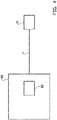
- FIG 4 A schematic view of an electric vehicle supply equipment, EVSE, 20 according to an embodiment of the invention, is shown in figure 4 .
- the EVSE 20 comprises the charging cable 1 and a charging connector 21.
- the EVSE 20, for example, is connected to a not shown alternating current, AC, grid via a transformer and/or a converter for receiving electrical energy from the AC grid.
- the received electrical energy is transformed and/or converted into DC suitable for charging an electric vehicle by the EVSE 20.
- the transformed and/or converted DC is intended for being supplied to a not shown electric vehicle via the charging cable 1, which may have a length of about 5.5 m, wherein the electric vehicle is connected to the EVSE 20 by the charging connector 21.
- the EVSE 20 charges the electric vehicle with a current equal to or up to 3000 A, when the EVSE 20 charges at a single charging cable 1, or to 500 A, when the EVSE 20 charges at two charging cables 1.
- the EVSE 20 further comprises a cooling unit 22 with, for example, a liquid coolant reservoir, in particular an ultrapure water/glycol mixture reservoir, a heat exchanger for cooling the liquid coolant, and a pump for circulating the coolant from the liquid coolant reservoir towards the charging connector 21 via the coolant supply tube 11.
- the charging connector 21 is configured for returning the coolant towards the cooling unit 22 via the coolant space 5 of each of the power wires 2, such that the coolant flows around the power conductor 3 of each power wire 2 for cooling the power wires 2.
- the pump for example, is configured to pump 7 litres of coolant through the coolant supply tube 11 per minute.
Landscapes
- Engineering & Computer Science (AREA)
- Power Engineering (AREA)
- Transportation (AREA)
- Mechanical Engineering (AREA)
- Electric Propulsion And Braking For Vehicles (AREA)
Priority Applications (3)
| Application Number | Priority Date | Filing Date | Title |
|---|---|---|---|
| EP21196620.5A EP4147903A1 (de) | 2021-09-14 | 2021-09-14 | Ladekabel zum laden eines elektrischen fahrzeugs und elektrische fahrzeugversorgungsausrüstung mit einem ladekabel |
| CN202211111252.2A CN115810448A (zh) | 2021-09-14 | 2022-09-13 | 对电动车充电的充电电缆和有充电电缆的电动车供电设备 |
| US17/943,563 US20230084987A1 (en) | 2021-09-14 | 2022-09-13 | Charging cable for charging an electric vehicle, and electric vehicle supply equipment with a charging cable |
Applications Claiming Priority (1)
| Application Number | Priority Date | Filing Date | Title |
|---|---|---|---|
| EP21196620.5A EP4147903A1 (de) | 2021-09-14 | 2021-09-14 | Ladekabel zum laden eines elektrischen fahrzeugs und elektrische fahrzeugversorgungsausrüstung mit einem ladekabel |
Publications (1)
| Publication Number | Publication Date |
|---|---|
| EP4147903A1 true EP4147903A1 (de) | 2023-03-15 |
Family
ID=77801457
Family Applications (1)
| Application Number | Title | Priority Date | Filing Date |
|---|---|---|---|
| EP21196620.5A Pending EP4147903A1 (de) | 2021-09-14 | 2021-09-14 | Ladekabel zum laden eines elektrischen fahrzeugs und elektrische fahrzeugversorgungsausrüstung mit einem ladekabel |
Country Status (3)
| Country | Link |
|---|---|
| US (1) | US20230084987A1 (de) |
| EP (1) | EP4147903A1 (de) |
| CN (1) | CN115810448A (de) |
Cited By (2)
| Publication number | Priority date | Publication date | Assignee | Title |
|---|---|---|---|---|
| US20220305926A1 (en) * | 2021-03-26 | 2022-09-29 | Toyota Motor Engineering & Manufacturing North America, Inc. | Temperature regulation of vehicle charging components |
| DE102024114628A1 (de) * | 2024-05-24 | 2025-11-27 | Leoni Kabel Gmbh | Innenkonturschlauch |
Families Citing this family (5)
| Publication number | Priority date | Publication date | Assignee | Title |
|---|---|---|---|---|
| US12327949B2 (en) | 2022-04-20 | 2025-06-10 | Rivian Ip Holdings, Llc | Header apparatus for vehicle battery pack |
| US11881571B1 (en) * | 2022-12-28 | 2024-01-23 | Rivian Ip Holdings, Llc | Thermal management in battery components |
| US20240355507A1 (en) * | 2023-04-18 | 2024-10-24 | Southwire Company, Llc | Tube with spokes |
| TWI884673B (zh) * | 2024-01-03 | 2025-05-21 | 財團法人工業技術研究院 | 電纜線散熱結構及其散熱方法 |
| DE102024132428A1 (de) * | 2024-11-07 | 2026-05-07 | Dr. Ing. H.C. F. Porsche Aktiengesellschaft | Kühlbare Stromleitung und Batterie |
Citations (11)
| Publication number | Priority date | Publication date | Assignee | Title |
|---|---|---|---|---|
| DE2951432A1 (de) * | 1978-12-21 | 1980-07-10 | Volvo Ab | Koaxialkabel fuer hohe amperezahlen |
| US20160270257A1 (en) * | 2010-10-14 | 2016-09-15 | Gregory Thomas Mark | Actively cooled electrical connection |
| WO2017133893A1 (en) * | 2016-02-01 | 2017-08-10 | Huber+Suhner Ag | Cable assembly |
| CN206864231U (zh) * | 2017-05-24 | 2018-01-09 | 深圳宝兴电线电缆制造有限公司 | 一种电动汽车冷却充电电缆 |
| CN108806874A (zh) * | 2018-05-25 | 2018-11-13 | 成都大唐线缆有限公司 | 一种适用于动力传输线的制冷电缆 |
| CN109036694A (zh) * | 2018-07-31 | 2018-12-18 | 江苏大学 | 一种大功率充电连接器用冷却电缆 |
| DE202019105511U1 (de) * | 2019-10-07 | 2020-03-03 | Abb Schweiz Ag | Elektrofahrzeug-Ladeanordnung zum Laden eines Elektrofahrzeugs |
| DE102019112843B3 (de) * | 2019-05-16 | 2020-09-03 | Dr. Ing. H.C. F. Porsche Aktiengesellschaft | Kraftfahrzeugladekabel |
| US20200317070A1 (en) * | 2016-06-01 | 2020-10-08 | Phoenix Contact E-Mobility Gmbh | Charging Cable For Transmitting Electric Energy, Charging Plug and Charging Station For Discharging Electric Energy to a Recipient of Electric Energy |
| DE102019208685A1 (de) * | 2019-06-14 | 2020-12-17 | Vitesco Technologies GmbH | Starkstromkabel |
| WO2021013369A1 (en) * | 2019-07-25 | 2021-01-28 | Abb Schweiz Ag | Heavy-current charging cable for charging an electric vehicle |
Family Cites Families (9)
| Publication number | Priority date | Publication date | Assignee | Title |
|---|---|---|---|---|
| EP0503129A1 (de) * | 1991-03-09 | 1992-09-16 | kabelmetal electro GmbH | Koaxiales elektrisches Hochfrequenzkabel |
| US9123458B2 (en) * | 2009-06-09 | 2015-09-01 | Essential Sound Products, Inc. | Power cable |
| JP5573696B2 (ja) * | 2011-01-21 | 2014-08-20 | 日立金属株式会社 | 導電路 |
| JP2012221739A (ja) * | 2011-04-08 | 2012-11-12 | Shin Etsu Polymer Co Ltd | ケーブル |
| EP3211642A1 (de) * | 2016-02-23 | 2017-08-30 | LEONI Kabel Holding GmbH | Datenkabel und litzenleiter |
| EP3588686B1 (de) * | 2018-06-27 | 2021-02-24 | ABB Schweiz AG | Elektrofahrzeugladeausrüstung |
| AU2020203147B2 (en) * | 2019-05-23 | 2025-05-15 | Prysmian S.P.A. | Power cable with enhanced ampacity |
| DE102020120819A1 (de) * | 2020-08-06 | 2022-02-10 | Leoni Kabel Gmbh | Gekühltes Ladekabel |
| US11935671B2 (en) * | 2021-01-27 | 2024-03-19 | Apple Inc. | Spiral wound conductor for high current applications |
-
2021
- 2021-09-14 EP EP21196620.5A patent/EP4147903A1/de active Pending
-
2022
- 2022-09-13 CN CN202211111252.2A patent/CN115810448A/zh active Pending
- 2022-09-13 US US17/943,563 patent/US20230084987A1/en active Pending
Patent Citations (11)
| Publication number | Priority date | Publication date | Assignee | Title |
|---|---|---|---|---|
| DE2951432A1 (de) * | 1978-12-21 | 1980-07-10 | Volvo Ab | Koaxialkabel fuer hohe amperezahlen |
| US20160270257A1 (en) * | 2010-10-14 | 2016-09-15 | Gregory Thomas Mark | Actively cooled electrical connection |
| WO2017133893A1 (en) * | 2016-02-01 | 2017-08-10 | Huber+Suhner Ag | Cable assembly |
| US20200317070A1 (en) * | 2016-06-01 | 2020-10-08 | Phoenix Contact E-Mobility Gmbh | Charging Cable For Transmitting Electric Energy, Charging Plug and Charging Station For Discharging Electric Energy to a Recipient of Electric Energy |
| CN206864231U (zh) * | 2017-05-24 | 2018-01-09 | 深圳宝兴电线电缆制造有限公司 | 一种电动汽车冷却充电电缆 |
| CN108806874A (zh) * | 2018-05-25 | 2018-11-13 | 成都大唐线缆有限公司 | 一种适用于动力传输线的制冷电缆 |
| CN109036694A (zh) * | 2018-07-31 | 2018-12-18 | 江苏大学 | 一种大功率充电连接器用冷却电缆 |
| DE102019112843B3 (de) * | 2019-05-16 | 2020-09-03 | Dr. Ing. H.C. F. Porsche Aktiengesellschaft | Kraftfahrzeugladekabel |
| DE102019208685A1 (de) * | 2019-06-14 | 2020-12-17 | Vitesco Technologies GmbH | Starkstromkabel |
| WO2021013369A1 (en) * | 2019-07-25 | 2021-01-28 | Abb Schweiz Ag | Heavy-current charging cable for charging an electric vehicle |
| DE202019105511U1 (de) * | 2019-10-07 | 2020-03-03 | Abb Schweiz Ag | Elektrofahrzeug-Ladeanordnung zum Laden eines Elektrofahrzeugs |
Cited By (4)
| Publication number | Priority date | Publication date | Assignee | Title |
|---|---|---|---|---|
| US20220305926A1 (en) * | 2021-03-26 | 2022-09-29 | Toyota Motor Engineering & Manufacturing North America, Inc. | Temperature regulation of vehicle charging components |
| US11987142B2 (en) * | 2021-03-26 | 2024-05-21 | Toyota Motor Engineering & Manufacturing North America, Inc. | Temperature regulation of vehicle charging components |
| DE102024114628A1 (de) * | 2024-05-24 | 2025-11-27 | Leoni Kabel Gmbh | Innenkonturschlauch |
| WO2025242776A1 (de) | 2024-05-24 | 2025-11-27 | Leoni Kabel Gmbh | Innenkonturschlauch |
Also Published As
| Publication number | Publication date |
|---|---|
| US20230084987A1 (en) | 2023-03-16 |
| CN115810448A (zh) | 2023-03-17 |
Similar Documents
| Publication | Publication Date | Title |
|---|---|---|
| US20230084987A1 (en) | Charging cable for charging an electric vehicle, and electric vehicle supply equipment with a charging cable | |
| US11760217B2 (en) | Liquid cooled charging cable system | |
| US10800276B2 (en) | Electrical charging arrangement with charging socket for vehicle | |
| US12083911B2 (en) | Heavy-current charging cable for charging an electric vehicle | |
| EP4004953B1 (de) | Starkstromladekabel zum laden eines elektrischen fahrzeugs | |
| JP7330368B2 (ja) | 電気車充電用ケーブル | |
| CN115485170A (zh) | 用于电动车辆充电和配电的高功率屏蔽母线 | |
| CN110869237A (zh) | 电动汽车的充电布置以及用于操作充电布置的方法 | |
| US20250007267A1 (en) | Cooled busbar for electric power distribution | |
| CN220106098U (zh) | 一种新能源汽车充电枪用水冷线缆及充电枪 | |
| JP2017097965A (ja) | 内部冷却ケーブル | |
| CN217061575U (zh) | 扁形屏蔽高压电缆 | |
| CN220821175U (zh) | 一种液体冷却充电电缆 | |
| CN118366719A (zh) | 液冷散热电缆 | |
| CN119677653A (zh) | 电线组件和机动车 | |
| US20250222801A1 (en) | Lower loss charging cable | |
| US20240355507A1 (en) | Tube with spokes | |
| US20260014882A1 (en) | Power Line Assembly and Motor Vehicle | |
| US12617302B2 (en) | Fast charge device for an electric or hybrid vehicle | |
| KR20250133575A (ko) | 냉각 기능을 갖는 충전케이블 | |
| CN120636938A (zh) | 一种充电桩专用散热电缆及制备方法 | |
| KR20250133574A (ko) | 냉각 기능을 갖는 충전케이블 |
Legal Events
| Date | Code | Title | Description |
|---|---|---|---|
| PUAI | Public reference made under article 153(3) epc to a published international application that has entered the european phase |
Free format text: ORIGINAL CODE: 0009012 |
|
| STAA | Information on the status of an ep patent application or granted ep patent |
Free format text: STATUS: THE APPLICATION HAS BEEN PUBLISHED |
|
| AK | Designated contracting states |
Kind code of ref document: A1 Designated state(s): AL AT BE BG CH CY CZ DE DK EE ES FI FR GB GR HR HU IE IS IT LI LT LU LV MC MK MT NL NO PL PT RO RS SE SI SK SM TR |
|
| STAA | Information on the status of an ep patent application or granted ep patent |
Free format text: STATUS: REQUEST FOR EXAMINATION WAS MADE |
|
| 17P | Request for examination filed |
Effective date: 20230915 |
|
| RBV | Designated contracting states (corrected) |
Designated state(s): AL AT BE BG CH CY CZ DE DK EE ES FI FR GB GR HR HU IE IS IT LI LT LU LV MC MK MT NL NO PL PT RO RS SE SI SK SM TR |
|
| TPAC | Observations filed by third parties |
Free format text: ORIGINAL CODE: EPIDOSNTIPA |
|
| STAA | Information on the status of an ep patent application or granted ep patent |
Free format text: STATUS: EXAMINATION IS IN PROGRESS |
|
| 17Q | First examination report despatched |
Effective date: 20260121 |