EP4147908B1 - Ensemble table pour camion - Google Patents
Ensemble table pour camion Download PDFInfo
- Publication number
- EP4147908B1 EP4147908B1 EP21195442.5A EP21195442A EP4147908B1 EP 4147908 B1 EP4147908 B1 EP 4147908B1 EP 21195442 A EP21195442 A EP 21195442A EP 4147908 B1 EP4147908 B1 EP 4147908B1
- Authority
- EP
- European Patent Office
- Prior art keywords
- swing arm
- table assembly
- turntable
- pivot
- support plate
- Prior art date
- Legal status (The legal status is an assumption and is not a legal conclusion. Google has not performed a legal analysis and makes no representation as to the accuracy of the status listed.)
- Active
Links
Images


Classifications
-
- B—PERFORMING OPERATIONS; TRANSPORTING
- B60—VEHICLES IN GENERAL
- B60N—SEATS SPECIALLY ADAPTED FOR VEHICLES; VEHICLE PASSENGER ACCOMMODATION NOT OTHERWISE PROVIDED FOR
- B60N3/00—Arrangements or adaptations of other passenger fittings, not otherwise provided for
- B60N3/001—Arrangements or adaptations of other passenger fittings, not otherwise provided for of tables or trays
- B60N3/002—Arrangements or adaptations of other passenger fittings, not otherwise provided for of tables or trays of trays
-
- B—PERFORMING OPERATIONS; TRANSPORTING
- B60—VEHICLES IN GENERAL
- B60N—SEATS SPECIALLY ADAPTED FOR VEHICLES; VEHICLE PASSENGER ACCOMMODATION NOT OTHERWISE PROVIDED FOR
- B60N2205/00—General mechanical or structural details
- B60N2205/20—Measures for elimination or compensation of play or backlash
Definitions
- This invention relates to a table assembly for equipping a vehicle, in particular a heavy-duty vehicle like a truck.
- the driver of a truck is likely to also perform various activities in his truck, like taking his lunches, resting, doing paperwork or sleeping.
- the driver may also be accompanied by passengers, who will also carry out their own activities either while the truck is driven or when the truck is parked. It is therefore handy to be able to temporarily arrange various pieces of equipment in the truck cabin, corresponding to the requirements of the moment.
- the dashboard of the truck usually offers a storage space with some opened shelves and some closed compartments as well.
- This storage space is often not sufficient in terms of storage capacity, or not very well suited to the needs of the driver or of the passengers.
- the geometry of this storage space cannot usually be modified, or only to a very limited extent.
- movable table assemblies which are for instance known from DE 10 2013 222449 A1 , DE 297 08 702 U1 , US 2 549 753 A , US 2 510 436 A , US 1 894 991 A and US 688 230 A .
- the device should be adjustable and should be orientable to provide various geometrical configurations.
- the device should also be easy to dismantle and has to be safe to operate.
- the installation of the device should not negatively affect the comfort of the cabin. In particular, noise and vibration levels should not be increased once the device is fitted.
- the present invention proposes a table assembly according to claim 1.
- the two degrees of freedom of pivotal movement provide a good flexibility and numerous possibilities to configurate the table assembly.
- the table assembly can be adjusted to receive equipment in various situations. Furthermore, both the swing arm and the turntable will remain in position under the mechanical constraints associated with normal driving of the vehicle. Therefore, the proposed table assembly provides a very versatile equipment that can be used by driver and passengers, in driving or non-driving conditions.
- the first predetermined torque threshold is higher than the second predetermined torque threshold.
- the first predetermined torque threshold is comprised between 2,6 N.m and 3,8 N.m.
- the second predetermined torque threshold is comprised between 3,8 N.m and 5,8 N.m.
- the swing arm comprises a first pivot extending about a first axis.
- the first pivot is supported by the support plate.
- the swing arm comprises a second pivot extending about a second axis.
- the turntable is supported by the second pivot.
- the swing arm can be moved continuously between the stowed position and the extended position.
- the swing arm can be moved among a set of discrete stable positions.
- the turntable can be moved continuously relatively to the swing arm.
- the turntable can be moved relatively to the swing arm among a set of discrete stable positions.
- the first pivot extends from a first end of the swing arm.
- the second pivot extends from a second end of the swing arm.
- the swing arm is metallic.
- the swing arm is made of cast aluminum alloy.
- the length of the swing arm is about 40 centimeters.
- the width of the swing arm is about 35 millimeters.
- the length of the turntable is about 42 centimeters.
- the width of the turntable is about 30 centimeters.
- an axis of the first pivot of the swing arm makes with a vertical axis an angle comprised between 0° et 15°.
- an axis of the first pivot of the swing arm is vertical.
- an axis of the second pivot of the swing arm makes with the vertical axis an angle comprised between 0° et 15°.
- an axis of the second pivot of the swing arm is vertical.
- the axis of the first pivot is parallel to the axis of the second pivot.
- the first pivot and the second pivot extend from the swing arm in opposite directions.
- an angular amplitude of the swing arm between the stowed position and the extended position is comprised between 0° and 90°.
- an angular amplitude of the turntable relatively to the swing arm is comprised between -40° and 210°.
- a translation motion of the swing arm relatively to the support plate is blocked when the table assembly is in use position.
- a translation motion of the turntable relatively to the second pivot of the swing arm is blocked when the table assembly is in use position.
- the support plate comprises a first locking device configured for holding the swing arm in place relatively to the support plate.
- the first locking device can be selectively activated and deactivated.
- the first locking device comprises a first rotating knob linked to the support plate.
- the first rotating knob is fixed to a threaded shaft, and the threaded shaft is engaged in a threaded bore of the support plate.
- the turntable comprises a second locking device configured for holding the turntable in place relatively to the swing arm.
- the second locking device can be selectively activated and deactivated.
- a swiveling motion of the turntable relatively to the swing arm can be blocked by a second locking device.
- the second locking device comprises a second rotating knob linked to the turntable.
- the swing arm comprises a first pivot extending about a first axis and a second pivot extending about a second axis
- the swing arm comprises a first portion extending transversely to the first axis and a second portion extending transversely to the second axis
- the first portion and the second portion are offset one from the other along the first axis.
- the swing arm comprises a curved portion linking the first portion and second portion.
- the curved portion comprises a first curvature directed towards the first pivot and comprises a second curvature directed in opposite direction.
- the first pivot of the swing arm is cylindrical
- the support plate comprises a cylindrical bore
- the first pivot is inserted in the cylindrical bore of the support plate.
- the second pivot of the swing arm is cylindrical
- the turntable comprises a cylindrical bore
- the second pivot is inserted in the cylindrical bore of the turntable.
- the first pivot of the swing arm has a toothed crossed section.
- the first pivot is inserted in a sleeve fixed in a housing of the support plate.
- the second pivot has a toothed crossed section.
- the support plate comprises a protection pad, and the swing arm is in contact with the protection pad when the swing arm is in the stowed position.
- the protection pad comprises a first wing with which a lateral surface of the swing arm is in contact when the swing arm is in the stowed position.
- the first wing of the protection pad extends in a first plane parallel to the axis of the first pivot.
- the protection pad comprises a second wing with which a lateral surface of the swing arm is in contact when the swing arm is in the extended position.
- the second wing extends in a second plane parallel to the axis of the first pivot.
- a cross-section of the swing arm has a U shape defining a base and two sides wings.
- the base of the U-shaped cross-section is perpendicular to the axis of the first pivot.
- the sides wings of the U-shaped cross-section are parallel to the axis of the first pivot.
- the axis of the first pivot is located between the side wings.
- the base of the U-shaped cross section is orientated away from the surface of the dashboard.
- a side wing rests against the first wing of the protection pad when the swing arm is in the stowed position.
- a side wing rests against the second wing of the protection pad when the swing arm is in the extended position.
- the protection pad comprises a base extending in a plane perpendicular to the axis of the first pivot, and a bottom surface of the swing arm is in contact with the base when the swing arm is in the stowed position.
- the protection pad is in polyacetal and polyoxymethylene (POM) material.
- POM polyoxymethylene
- the protection pad comprises an anti-friction additive.
- the swing arm comprises a friction insert configured to slide over the protection pad when the swing arm is rotated from one position between the stowed position and the extended position to the other position.
- the friction insert is in polyacetal and polyoxymethylene (POM) material.
- POM polyoxymethylene
- the friction insert is fixed to swing arm by one or several fixing screws.
- the turntable comprises a protection mat configured to be in contact with the dashboard when the swing arm is in the stowed position.
- the invention also relates to a retrofit kit comprising :
- the support plate carries internal mechanical constraints when the support plate of the table assembly is fixed to the bracket.
- the invention is also related to a truck comprising a table assembly as described earlier, or comprising a retrofit kit as described above.
- first or second element or by first or second parameter.
- This index system is used only for differentiating elements that are similar, but not identical. This index system does not imply a priority of one element, or parameter, over another one, and the different terms may be exchanged.
- a device or a subsystem When a device or a subsystem comprises a given element, it doesn't exclude the presence of other elements in this device or subsystem.
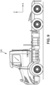
- Figure 9 shows a truck 100 comprising a table assembly 1 according to the invention, that will be described in detail here below.
- the truck 100 is for example a long-haul truck.
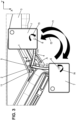
- Figure 3 illustrates in a non-limiting manner a table assembly 1 for a truck 100, configured for being moved between a stowed position S and an extended position E, the table assembly 1 comprising :
- the two degrees of freedom of pivotal movement provide a good flexibility and numerous possibilities to configurate the table assembly 1.
- the table assembly 1 can be adjusted to receive equipment in various situations. Furthermore, both the swing arm 4 and the turntable 7 will remain in position under the mechanical constraints associated with normal driving of the vehicle. Therefore, the proposed table assembly 1 provides a very versatile installation that can be used by both driver and passengers, in driving or non-driving conditions.
- arrow f1 indicates the travel of the table assembly 1 when it is moved from the stowed position S to the extended position E.
- the arrow f2 indicates the travel of the table assembly 1 when moved the other way round, meaning from the extended position E to the stowed position S.
- arrow f3 indicates a clockwise rotation of the turntable 7, when viewed from the top of the cabin
- arrow f4 indicates an anti-clockwise rotation of the turntable 7.
- the table assembly 1 is intended to be moved by the effort of a user. For this, the user may exert a force on the swing arm 4, or on the turntable 7, or any protruding element linked to one of the previous elements.
- the rotation of the swing arm 4 is independent of the rotation of the turntable 7. This means the swing arm 4 can be rotated relatively to the support plate 2 while the turntable 7 remains fixed relatively to the swing arm 4.
- the turntable 7 orientation relatively to the swing arm 4 can be modified while the angular position of the swing arm 4 relatively to the support plate 2 remains constant.
- the position of the swing arm 4 relatively to the support plate 2 and the position of the turntable 7 relatively to the swing arm 4 can be simultaneously modified.
- the swing arm 4 can be rotated relatively to the support plate 2 only if the torque applied between the swing arm 4 and the support plate 2 exceeds a first predetermined threshold Th1. Thanks to this feature, the swing arm 4 will remain in a fixed position under the mechanical constraints associated with normal driving of the vehicle. These mechanical constraints come for example from the vibrations, small shocks, slopes and camber of the road on which the truck is driven. Different values of the first predetermined threshold Th1 can be obtained through design of internal clearances and materials selection. Similarly, the turntable 7 can be moved relatively to the swing arm 4 only if the torque applied between the turntable 7 and the swing arm 4 exceeds a second predetermined threshold Th2. The turntable 7 will thus also remain in position under mechanical constraints associated with normal driving of the vehicle.
- the first predetermined torque threshold Th1 is higher than the second predetermined torque threshold Th2.
- the first predetermined torque threshold Th1 is comprised between 2,6 N.m and 3,8 N.m.
- the second predetermined torque threshold Th2 is comprised between 3,8 N.m and 5,8 N.m.
- the swing arm 4 comprises a first pivot 5 extending about a first axis Z1.
- the first pivot 5 is supported by the support plate 2.
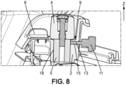
- Figure 8 shows that the first pivot 5 is inserted in a housing 18 of the support plate 2.
- the swing arm 4 also comprises a second pivot 6 extending about a second axis Z2.
- the turntable 7 is supported by the second pivot 6.
- the swing arm 4 can be moved continuously between the stowed position S and the extended position E.
- the swing arm 4 can steadily take any angular position comprised between the stowed position S and the extended position E.
- the swing arm 4 can be moved among a set of discrete stable positions.
- the position of the swing arm 4 can be switched between various discrete positions, and intermediate positions between the discrete positions are only transient positions.
- the first pivot 5 of the swing arm 4 has a toothed crossed section.
- the top 35 of the teeths is further away from the axis Z1 than the gap 36 between the teeths.
- the cross section of the pivot 5 is similar to an hexagon with rounded vertices.
- the first pivot 5 may be inserted in a sleeve fixed in a housing of the support plate 2.
- the sleeve has a complementary shape to the toothed cross section of the pivot 5.
- the material and the dimensions of the sleeve are selected so the torque required to shift the pivot 5 by one tooth relatively to the sleeve is at least equal to the first predetermined threshold Th1.
- the second pivot 6 has a toothed crossed section.
- This toothed crossed section ensures that the torque required to shift the second pivot 6 by one tooth is at least equal to the second predetermined threshold Th2.
- the turntable 7 can be moved relatively to the swing arm 4 among a set of discrete stable positions. Intermediate positions between these discrete positions are only transient positions that are occupied during the transition between one stable position and another stable position.
- the turntable 7 can be moved continuously relatively to the swing arm 4.
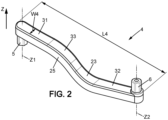
- Figure 2 illustrates the swing arm 4 in isolation.
- the first pivot 5 extends from a first end of the swing arm 4.
- the second pivot 6 extends from a second end of the swing arm 4.
- the swing arm 4 has an elongated shape similar to a rod.
- the swing arm 4 is metallic.
- the swing arm 4 is for example made of cast aluminum alloy. Adequate strength and stiffness can thus be provided. Furthermore, a variety of different shapes can easily be obtained.
- the length L4 of the swing arm 4 is about 40 centimeters.
- the width W4 of the swing arm 4 is about 35 millimeters.
- the first pivot 5 and the second pivot 6 extend from the swing arm 4 in opposite directions. In other words, the first pivot 5 and the second pivot 6 are pointing in opposition directions.
- the swing arm 4 is axially located, along the direction of extension of the first pivot 5 and the second pivot 6, between the first pivot 5 and the second pivot 6.
- an axis 1 of the first pivot 5 of the swing arm 4 makes with a vertical axis Z an angle A comprised between 0° et 15°.
- the axis Z1 of the first pivot 5 of the swing arm 4 is here vertical.
- an axis Z2 of the second pivot 6 of the swing arm 4 makes with the vertical Z axis an angle comprised between 0° et 15°.
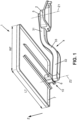
- the axis Z2 of the second pivot 6 of the swing arm 4 is here vertical. As illustrated for example on figure 1 , the axis Z1 of the first pivot 5 is parallel to the axis Z2 of the second pivot 6.
- An angular amplitude A of the swing arm 4 between the stowed position S and the extended position E is comprised between 70° and 110°.
- An angular amplitude of the turntable 7 relatively to the swing arm 4 is comprised between 120° and 210°.
- the length L7 of the turntable 7 is about 42 centimeters.
- the width W7 of the turntable 7 is about 30 centimeters. These dimensions are chosen so that the turntable 7 can accommodate the various pieces of equipment that the cabin occupants may need to install.
- a translation motion of the swing arm 4 relatively to the support plate 2 is blocked when the table assembly 1 is in use position.
- a translation motion of the turntable 7 relatively to the second pivot 6 of the swing arm 4 is blocked when the table assembly 1 is in use position.
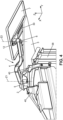
- the turntable 7 In the stowed position S of the table assembly 1, the turntable 7 is supported by the dashboard 3. In other words, in the stowed position S there's a least a portion of a bottom surface of the turntable 7 which is in contact with the dashboard 3 and thus supported vertically by the dashboard 3. This aspect is best seen on figure 4 .
- the turntable 7 In the extended position E, the turntable 7 is overhanging the dashboard 3. In other words, there's no vertical support provided by the dashboard 3 to the bottom surface of the turntable 7.
- the turntable 7 When the table assembly 1 is in extended position E, the turntable 7 may be vertically facing the floor of the cabin of the truck 100.
- the support plate 2 comprises a first locking device 9 configured for holding the swing arm 4 in place relatively to the support plate 2.
- the first locking device 9 can be selectively activated and deactivated.
- the angular position of the swing arm 4 remains constant when the first locking device is activated.
- the swing arm 4 can be swiveled by a user when the first locking device 9 is deactivated.
- the position of the swing arm 4 can then by adjusted by the user according to its needs. In other words, a swiveling motion of the swing arm 4 relatively to the support plate 2 can be selectively blocked or released by a first locking device 9.
- the first locking device 9 comprises a first rotating knob 11 linked to the support plate 2.
- the first rotating knob 11 is fixed to a threaded shaft 13, and the threaded shaft 13 is engaged in a threaded bore 15 of the support plate 2.
- a rotation of the first rotating knob 11 pushes an axial end of the first threaded shaft 13 against the first pivot 5.
- the mechanical constraint that is generated prevents a rotation of the swing arm 4 relatively to the support plate 2.
- Different locking mechanisms can also be considered.
- the turntable 7 also comprises a second locking device 10 configured for holding the turntable 7 in place relatively to the swing arm 4.
- the second locking device 10 can be selectively activated and deactivated. In other words, a swiveling motion of the turntable 7 relatively to the swing arm 4 can be blocked by a second locking device 10.
- the angular position of the turntable 7 relatively to the swing arm 4 remains constant when the second locking device 9 is activated.
- Turntable 7 can be swiveled when the second locking device 10 is deactivated, which allows the position of the turntable 7 to be adjusted as required by the user.
- a swiveling motion of the turntable 7 relatively to the swing arm 4 can be selectively blocked or released by a second locking device 10.
- the second locking device 10 comprises a second rotating knob 12 linked to the turntable 7.
- the second rotating knob 12 is fixed to a second threaded shaft, and the second threaded shaft is engaged in a threaded bore of the turntable 7.
- a rotation of the second knob 12 pushes an axial end of the second threaded shaft against the second pivot 6.
- the mechanical constraint that is generated prevents a rotation of the turntable 7 relatively to the swing arm 4.
- the turntable 7 can be disengaged from the swing arm 4.
- the swing arm 4 can also be mechanically disengaged from the support plate 2.
- the turntable 7 can be stored when the table assembly 1 is not in use.
- the sub-assembly comprising the swing arm 4 equipped with the turntable 7 can also be stored when there's no intention to use the table assembly 1. It can for example be stored under the bunk of the cabin. The table assembly 1 can then be easily reassembled so that it comes back in normal use conditions.
- the swing arm 4 comprises a first pivot 5 extending about a first axis Z1 and a second pivot 6 extending about a second axis Z2.
- the swing arm 4 comprises a first portion 31 extending transversely to the first axis Z1 and a second portion 32 extending transversely to the second axis Z2.
- the first portion 31 and the second portion 32 are offset one from the other along the first axis Z1.
- the swing arm 4 comprises a curved portion 33 linking the first portion 31 and second portion 32.
- the curved portion 33 comprises a first curvature directed towards the first pivot 5 and comprises a second curvature directed in the opposite direction.
- the swing arm 4 has a shape similar to a flat 'S'.
- the offset along the first axis Z1 between the first portion 31 and the second portion 32 is selected so that the top surface of the turntable 7 is aligned, or nearly aligned, with the first portion 31. Furthermore, this offset may compensate the vertical height difference existing between the first portion 31 of the swing arm 4 and the top surface of the dashboard 3. The bottom of the turntable 7 can be more easily supported by the top surface of the dashboard 3, as illustrated on figure 4 .
- the first pivot 5 of the swing arm 4 is cylindrical
- the support plate 2 comprises a cylindrical bore
- the first pivot 5 is inserted in the cylindrical bore of the support plate 2.
- the second pivot 6 of the swing arm 4 is cylindrical
- the turntable 7 comprises a cylindrical bore 17, and the second pivot 6 is inserted in the cylindrical bore 17 of the turntable 7.
- the support plate 2 comprises a protection pad 8, and the swing arm 4 is in contact with the protection pad 8 when the swing arm 4 is in the stowed position S.
- the protection pad 8 comprises a first wing 21 with which a lateral surface 19a of the swing arm 4 is in contact when the swing arm 4 is in the stowed position S.
- the first wing 21 of the protection pad 8 extends in a first plane parallel to the axis Z1 of the first pivot 5.
- the protection pad 8 also comprises a second wing 22 with which a lateral surface 19b of the swing arm 4 is in contact when the swing arm 4 is in the extended position E.
- the second wing 22 extends in a second plane parallel to the axis of the first pivot 5.
- the relative position of the first wing 21 and of the second wing 22 define the amplitude between the stowed position S and the extended position E.
- the protection pad 8 prevents the swing-arm 4 from wearing and damaging the dashboard 3. Scratches that may result from repeated contacts and impacts of swing arm 3 against dashboard 3 are avoided.
- the protection pad 8 is for example in polyacetal, or in polyoxymethylene (POM) material.
- a cross-section of the swing arm 4 has a U shape defining a base 23 and two sides wings 24, 25.
- the base 23 of the U-shaped cross-section is perpendicular to the axis Z1 of the first pivot 5.
- the sides wings 24, 25 of the U-shaped cross-section are parallel to the axis Z1 of the first pivot 5.
- the axis Z1 of the first pivot 5 is located between the side wings 24, 25.
- the base 23 of the U-shaped cross section is orientated away from the surface of the dashboard 3. In other words, the base of the U is facing upwards when the table assembly 1 is installed in the truck 100 and ready for normal use.
- a side wing 24 rests against the first wing 21 of the protection pad 8 when the swing arm 4 is in the stowed position S.
- a side wing 25 rests against the second wing 22 of the protection pad 8 when the swing arm 4 is in the extended position E.
- the first wing 21 of the protection pad 8 acts as a lateral end-stop for the rotation of the swing arm 4.
- the second wing 22 acts as another end-stop for the rotation of the swing arm 4.
- the protection pad 8 comprises a base 28 extending in a plane perpendicular to the axis Z1 of the first pivot 5, and a bottom surface 26 of the swing arm 4 is in contact with the base 28 when the swing arm 4 is in the stowed position S.
- a weight acting on the turntable 7 tends to push the swing arm 4 against the base 28 of the protection pad 8.
- the base 28 can provide a mechanical support to the swing arm 4 in case of deflection because of the weight of the loads put on the turntable 7.
- the protection pad 8 also prevents the creation of scratches on the top of the support plate 2, due to the repeated angular strokes of the swing arm 4.
- the protection pad 8 comprises an anti-friction additive.
- the swing arm 4 comprises a friction insert 20 configured to slide over the protection pad 8 when the swing arm 4 is rotated from one position between the stowed position S and the extended position E to the other position.
- a surface 27 of the friction insert 20 may be in contact with the base 28 of the protection pad 8.
- the bottom surface 26 of the swing arm 4 contacting the protection pad 8 is provided by the surface 27 of the friction insert 20.
- the friction insert 20 is fixed to swing arm 4 by one or several fixing screws 37. Other fixing solutions are possible, like clipping or over molding of the friction insert 20 on an internal surface of the swing arm 4.
- the friction insert 20 is in polyacetal and polyoxymethylene (POM) material.
- POM polyoxymethylene
- the turntable 7 comprises a protection mat 30 configured to be in contact with the dashboard 3 when the swing arm 4 is in the stowed position S.
- the protection mat 30 is fixed to a surface of the turntable 7 configured to face the dashboard 3.
- the protection mat 30 protects the dashboard 3 against possible damages of the dashboard 3 because of the repeated friction of the turntable 7 against the dashboard 3.
- the swing arm 4 further comprises a weakened area 34 configured to break when a mechanical constraint exerted on the swing arm 4 is higher than a third predefined threshold Th3. This weakened area is particularly visible on figure 7 .
- the swing arm 4 has a U-shaped cross section defining a base 23 linking two side wings 24,25, and each side wing 24,25 comprises a weakened area 34a, 34b configured to break when a mechanical constraint exerted on the swing arm 4 is higher than a fourth predefined threshold Th4,Th4'.
- each side wing 24, 25 of the U-shaped cross section of the swing arm 4 comprises a weakened zone 34a, 34b, ie a zone in which the wall is thinner than the rest of the side wing.
- the risk of injury for the falling person is eliminated, or at least reduced.
- the weakened area is designed to resist to the maximum payload recommended for the table assembly, while used according to normal use case.
- sharp edges are avoided on the external profile of the swing arm 4.
- a minimum radius is provided between the base 23 and each of the side wings 24, 25.
- the weakened area 34a, 34b can be a notch machined in a side wing on the U-shaped cross section of the swing arm 4.
- each side wing 24, 25 of the swing arm 4 comprises a machined notch 34a, 34b.
- the two notches 34a, 34b may face each other in a direction perpendicular to the main direction Y of the swing arm 4, as it the case on figure 7 .
- the two notches may also be offset along the direction perpendicular to the main direction Y.
- the weakened area 34 can also be a portion with a lower thickness in the casting. In other words, no machining is performed, and the notch is formed by the shape of the mold.
- Such a retrofit kit comprises :
- the bracket 40 is fixed to the supporting frame 38 of the dashboard 3.
- the support plate 2 is bolted to the bracket 40.
- the bracket 40 is an intermediate part that makes a mechanical link between the support plate 2 and the supporting frame 38 which is a structural part of the dashboard 3.
- the supporting frame 38 is able to carry the mechanicals loads generated by the weight and acceleration of the objects disposed on the turntable 7.
- the bracket 40 comprises two different bracket elements fixed to two different locations of the dashboard 3.
- the bracket elements are sufficiently spaced to resist to the bending moments generated by the loads disposed on the table assy 1.
- the support plate 2 carries internal mechanical constraints when the support plate 2 of the table assembly 1 is fixed to the bracket 40.
- the mechanical assembly of the support plate 2 and the bracket 40 is an hyperstatic assembly.
- the support plate 2 is not only pressed against the bracket 40, but receives also a bending moment that tends to distort the support plate.
- the internal constraints that are generated in the support plate 2 when the fixing bolts 29 are tightened limit the propagation of vibrations in the dashboard 3. Rattling noises due to vibrations are eliminated, or at least reduced.
- the truck 100 comprises a retrofit kit as described above.
- the installation of the retrofit kit provides the same functions and benefits as those of a truck on which the table assembly 1 is an original equipment.
Landscapes
- Engineering & Computer Science (AREA)
- Transportation (AREA)
- Mechanical Engineering (AREA)
- Vehicle Step Arrangements And Article Storage (AREA)
Claims (11)
- Assemblage de table (1) pour un camion (100), configuré pour être déplacé entre une position rangée (S) et une position étendue (E), l'ensemble table (1) comprenant :- une plaque de support (2) configurée pour être montée sur un tableau de bord (3) du camion (100),- un bras oscillant (4) monté de manière pivotante sur la plaque de support (2) autour d'un premier axe (Z1),- un plateau tournant (7) monté de manière pivotante sur le bras oscillant (4) autour d'un second axe (Z2),dans lequel le bras oscillant (4) est configuré pour conserver sa position angulaire tant qu'un couple appliqué sur le bras oscillant (4) est inférieur à un premier seuil prédéterminé (Th1),et dans lequel le plateau tournant (7) est configuré pour conserver sa position angulaire tant qu'un couple appliqué sur le plateau tournant (7) est inférieur à un second seuil prédéterminé (Th2), caractérisé en ce que la plaque de support (2) comprend un tampon de protection (8), et dans lequel le bras pivotant (4) est en contact avec le tampon de protection (8) lorsque le bras pivotant (4) se trouve dans la position rangée (S), le bras pivotant (4) comprend un insert de friction (20) configuré pour glisser sur le tampon de protection (8) lorsque le bras pivotant (4) est tourné d'une position entre la position rangée (S) et la position étendue (E) à l'autre position.
- Assemblage de table (1) selon la revendication 1, dans lequel la plaque de support (2) comprend un premier dispositif de verrouillage (9) configuré pour maintenir le bras pivotant (4) en place par rapport à la plaque de support (2).
- Assemblage de table (1) selon la revendication 1 ou 2, dans lequel le plateau tournant (7) comprend un second dispositif de verrouillage (10) configuré pour maintenir le plateau tournant (7) en place par rapport au bras pivotant (4).
- Assemblage de table (1) selon l'une des revendications précédentes, dans lequel le bras pivotant (4) comprend un premier pivot (5) s'étendant autour d'un premier axe (Z1) et un second pivot (6) s'étendant autour d'un second axe (Z2), et dans lequel le bras oscillant (4) comprend une première partie (31) s'étendant transversalement au premier axe (Z1) et une seconde partie (32) s'étendant transversalement au second axe (Z2), et dans lequel la première partie (31) et la seconde partie (32) sont décalées l'une par rapport à l'autre le long du premier axe (Z1).
- Assemblage de table (1) selon l'une quelconque des revendications précédentes, dans lequel le tampon de protection (8) comprend une première aile (21) avec laquelle une surface latérale (19a) du bras pivotant (4) est en contact lorsque le bras pivotant (4) se trouve dans la position rangée (S).
- Assemblage de table (1) selon l'une quelconque des revendications précédentes, dans lequel le tampon de protection (8) comprend une base (28) s'étendant dans un plan perpendiculaire à l'axe du premier pivot (5), dans lequel une surface inférieure (26) du bras pivotant (4) est en contact avec la base (28) lorsque le bras pivotant (4) se trouve dans la position rangée (S).
- Assemblage de table des revendications précédentes, dans lequel le plateau tournant (7) comprend table (1) selon l'une quelconque des revendications précédentes, dans lequel le tampon de protection (8) est en polyacétal et en polyoxyméthylène (POM).
- Assemblage de table (1) selon l'une quelconque un tapis de protection (30) configuré pour être en contact avec le tableau de bord (3) lorsque le bras pivotant (4) se trouve dans la position rangée (S).
- Kit d'adaptation (50) comprenant :- un ensemble table (1) selon l'une des revendications précédentes,- un support (40) configuré pour être fixé à un cadre de support (38) du tableau de bord (3),dans lequel le support (40) est configuré pour recevoir la plaque de support (2) de l'ensemble table (1).
- Kit d'adaptation (50) selon la revendication précédente, dans lequel la plaque de support (2) porte des contraintes mécaniques internes lorsque la plaque de support (2) de l'ensemble table (1) est fixée au support (40).
- Camion (100) comprenant un ensemble table (1) selon l'une quelconque des revendications 1 à 8, ou comprenant un kit d'adaptation (50) selon l'une des revendications 9 ou 10.
Priority Applications (1)
| Application Number | Priority Date | Filing Date | Title |
|---|---|---|---|
| EP21195442.5A EP4147908B1 (fr) | 2021-09-08 | 2021-09-08 | Ensemble table pour camion |
Applications Claiming Priority (1)
| Application Number | Priority Date | Filing Date | Title |
|---|---|---|---|
| EP21195442.5A EP4147908B1 (fr) | 2021-09-08 | 2021-09-08 | Ensemble table pour camion |
Publications (3)
| Publication Number | Publication Date |
|---|---|
| EP4147908A1 EP4147908A1 (fr) | 2023-03-15 |
| EP4147908C0 EP4147908C0 (fr) | 2024-10-09 |
| EP4147908B1 true EP4147908B1 (fr) | 2024-10-09 |
Family
ID=77666324
Family Applications (1)
| Application Number | Title | Priority Date | Filing Date |
|---|---|---|---|
| EP21195442.5A Active EP4147908B1 (fr) | 2021-09-08 | 2021-09-08 | Ensemble table pour camion |
Country Status (1)
| Country | Link |
|---|---|
| EP (1) | EP4147908B1 (fr) |
Families Citing this family (1)
| Publication number | Priority date | Publication date | Assignee | Title |
|---|---|---|---|---|
| EP4556309A1 (fr) * | 2023-11-16 | 2025-05-21 | Volvo Truck Corporation | Ensemble table pour équiper un véhicule |
Family Cites Families (6)
| Publication number | Priority date | Publication date | Assignee | Title |
|---|---|---|---|---|
| US688230A (en) * | 1900-02-12 | 1901-12-03 | Gus Frey | Adjustable holder for embroidery-hoops. |
| US1894991A (en) * | 1931-02-05 | 1933-01-24 | John H Hayes | Bed tray |
| US2510436A (en) * | 1946-11-19 | 1950-06-06 | Trammell William Earnest | Attachment for fastening tables to automobile instrument panels |
| US2549753A (en) * | 1949-04-16 | 1951-04-24 | Joseph L Ashman | Instrument panel clamping bracket for adjusting automobile trays |
| DE29708702U1 (de) * | 1997-05-16 | 1997-07-17 | Herbert, Karl-Walter, 91091 Großenseebach | Einstellbare Halteeinrichtung für Bordcomputer in Kraftfahrzeugen, insbesondere für Laptop- oder Notebook-Computer |
| US9527456B2 (en) * | 2012-11-05 | 2016-12-27 | Kinetix Ag | Device for retaining flat, approximately rectangular appliances such as tablet computers or mobile telephones in the interior of a motor vehicle |
-
2021
- 2021-09-08 EP EP21195442.5A patent/EP4147908B1/fr active Active
Also Published As
| Publication number | Publication date |
|---|---|
| EP4147908A1 (fr) | 2023-03-15 |
| EP4147908C0 (fr) | 2024-10-09 |
Similar Documents
| Publication | Publication Date | Title |
|---|---|---|
| US5042864A (en) | Angularly movable seat construction for use in vehicle with sliding doors | |
| CN103874617B (zh) | 倾斜转向装置 | |
| CN101081606B (zh) | 用于汽车的头枕 | |
| US5323998A (en) | Seat slider mechanism | |
| US8316737B2 (en) | Electric clamping device for an adjustable motor vehicle steering column | |
| JP4174719B2 (ja) | 電車用側引戸装置 | |
| EP4147908B1 (fr) | Ensemble table pour camion | |
| US7344195B2 (en) | Dampener for a vehicle seat recliner | |
| US9308843B2 (en) | Adjustment apparatus for a swingable comfort element of a motor vehicle | |
| CA1304282C (fr) | Systeme de glissiere laterale pour cadre de siege de vehicule | |
| US5246270A (en) | Passenger seat arrangement | |
| EP3385114B1 (fr) | Dispositif de mouvement et de réglage longitudinaux de sièges de véhicules automobiles | |
| KR20150058397A (ko) | 차량 내부 구성요소용 수직 조정가능한 팔걸이 조립체 | |
| US4466594A (en) | Impact-displaceable rear view mirror mounting | |
| US3123401A (en) | Backrest construction | |
| WO1998017501A1 (fr) | Patte de support | |
| US12005815B2 (en) | Vehicle seat | |
| EP2492194B1 (fr) | Soute à bagages aérienne | |
| EP4144580B1 (fr) | Ensemble table avec ensemble de mise à niveau pour siège passager | |
| CN112282534A (zh) | 车门限位器和具有其的车辆 | |
| EP3145789B1 (fr) | Colonne de direction réglable et verrouillable mécaniquement | |
| US6373536B1 (en) | Latch for an on-board entertainment system | |
| JP2003048539A (ja) | 鉄道車両における分割車体の連結装置 | |
| JP2002036930A (ja) | 座席用テーブル | |
| US5261698A (en) | Shoulder belt position adjusting device for a seat belt assembly |
Legal Events
| Date | Code | Title | Description |
|---|---|---|---|
| PUAI | Public reference made under article 153(3) epc to a published international application that has entered the european phase |
Free format text: ORIGINAL CODE: 0009012 |
|
| STAA | Information on the status of an ep patent application or granted ep patent |
Free format text: STATUS: THE APPLICATION HAS BEEN PUBLISHED |
|
| AK | Designated contracting states |
Kind code of ref document: A1 Designated state(s): AL AT BE BG CH CY CZ DE DK EE ES FI FR GB GR HR HU IE IS IT LI LT LU LV MC MK MT NL NO PL PT RO RS SE SI SK SM TR |
|
| STAA | Information on the status of an ep patent application or granted ep patent |
Free format text: STATUS: REQUEST FOR EXAMINATION WAS MADE |
|
| 17P | Request for examination filed |
Effective date: 20230913 |
|
| RBV | Designated contracting states (corrected) |
Designated state(s): AL AT BE BG CH CY CZ DE DK EE ES FI FR GB GR HR HU IE IS IT LI LT LU LV MC MK MT NL NO PL PT RO RS SE SI SK SM TR |
|
| RIC1 | Information provided on ipc code assigned before grant |
Ipc: B60N 3/00 20060101AFI20240517BHEP |
|
| GRAP | Despatch of communication of intention to grant a patent |
Free format text: ORIGINAL CODE: EPIDOSNIGR1 |
|
| STAA | Information on the status of an ep patent application or granted ep patent |
Free format text: STATUS: GRANT OF PATENT IS INTENDED |
|
| INTG | Intention to grant announced |
Effective date: 20240628 |
|
| GRAS | Grant fee paid |
Free format text: ORIGINAL CODE: EPIDOSNIGR3 |
|
| GRAA | (expected) grant |
Free format text: ORIGINAL CODE: 0009210 |
|
| STAA | Information on the status of an ep patent application or granted ep patent |
Free format text: STATUS: THE PATENT HAS BEEN GRANTED |
|
| AK | Designated contracting states |
Kind code of ref document: B1 Designated state(s): AL AT BE BG CH CY CZ DE DK EE ES FI FR GB GR HR HU IE IS IT LI LT LU LV MC MK MT NL NO PL PT RO RS SE SI SK SM TR |
|
| REG | Reference to a national code |
Ref country code: CH Ref legal event code: EP |
|
| REG | Reference to a national code |
Ref country code: DE Ref legal event code: R096 Ref document number: 602021019848 Country of ref document: DE |
|
| REG | Reference to a national code |
Ref country code: IE Ref legal event code: FG4D |
|
| U01 | Request for unitary effect filed |
Effective date: 20241029 |
|
| U07 | Unitary effect registered |
Designated state(s): AT BE BG DE DK EE FI FR IT LT LU LV MT NL PT RO SE SI Effective date: 20241111 |
|
| PG25 | Lapsed in a contracting state [announced via postgrant information from national office to epo] |
Ref country code: HR Free format text: LAPSE BECAUSE OF FAILURE TO SUBMIT A TRANSLATION OF THE DESCRIPTION OR TO PAY THE FEE WITHIN THE PRESCRIBED TIME-LIMIT Effective date: 20241009 Ref country code: IS Free format text: LAPSE BECAUSE OF FAILURE TO SUBMIT A TRANSLATION OF THE DESCRIPTION OR TO PAY THE FEE WITHIN THE PRESCRIBED TIME-LIMIT Effective date: 20250209 |
|
| PG25 | Lapsed in a contracting state [announced via postgrant information from national office to epo] |
Ref country code: ES Free format text: LAPSE BECAUSE OF FAILURE TO SUBMIT A TRANSLATION OF THE DESCRIPTION OR TO PAY THE FEE WITHIN THE PRESCRIBED TIME-LIMIT Effective date: 20241009 |
|
| PG25 | Lapsed in a contracting state [announced via postgrant information from national office to epo] |
Ref country code: NO Free format text: LAPSE BECAUSE OF FAILURE TO SUBMIT A TRANSLATION OF THE DESCRIPTION OR TO PAY THE FEE WITHIN THE PRESCRIBED TIME-LIMIT Effective date: 20250109 |
|
| PG25 | Lapsed in a contracting state [announced via postgrant information from national office to epo] |
Ref country code: GR Free format text: LAPSE BECAUSE OF FAILURE TO SUBMIT A TRANSLATION OF THE DESCRIPTION OR TO PAY THE FEE WITHIN THE PRESCRIBED TIME-LIMIT Effective date: 20250110 |
|
| PG25 | Lapsed in a contracting state [announced via postgrant information from national office to epo] |
Ref country code: PL Free format text: LAPSE BECAUSE OF FAILURE TO SUBMIT A TRANSLATION OF THE DESCRIPTION OR TO PAY THE FEE WITHIN THE PRESCRIBED TIME-LIMIT Effective date: 20241009 |
|
| PG25 | Lapsed in a contracting state [announced via postgrant information from national office to epo] |
Ref country code: RS Free format text: LAPSE BECAUSE OF FAILURE TO SUBMIT A TRANSLATION OF THE DESCRIPTION OR TO PAY THE FEE WITHIN THE PRESCRIBED TIME-LIMIT Effective date: 20250109 |
|
| PG25 | Lapsed in a contracting state [announced via postgrant information from national office to epo] |
Ref country code: SM Free format text: LAPSE BECAUSE OF FAILURE TO SUBMIT A TRANSLATION OF THE DESCRIPTION OR TO PAY THE FEE WITHIN THE PRESCRIBED TIME-LIMIT Effective date: 20241009 |
|
| PG25 | Lapsed in a contracting state [announced via postgrant information from national office to epo] |
Ref country code: SK Free format text: LAPSE BECAUSE OF FAILURE TO SUBMIT A TRANSLATION OF THE DESCRIPTION OR TO PAY THE FEE WITHIN THE PRESCRIBED TIME-LIMIT Effective date: 20241009 |
|
| PG25 | Lapsed in a contracting state [announced via postgrant information from national office to epo] |
Ref country code: CZ Free format text: LAPSE BECAUSE OF FAILURE TO SUBMIT A TRANSLATION OF THE DESCRIPTION OR TO PAY THE FEE WITHIN THE PRESCRIBED TIME-LIMIT Effective date: 20241009 |
|
| PLBE | No opposition filed within time limit |
Free format text: ORIGINAL CODE: 0009261 |
|
| STAA | Information on the status of an ep patent application or granted ep patent |
Free format text: STATUS: NO OPPOSITION FILED WITHIN TIME LIMIT |
|
| 26N | No opposition filed |
Effective date: 20250710 |
|
| U20 | Renewal fee for the european patent with unitary effect paid |
Year of fee payment: 5 Effective date: 20250925 |