EP4147925A1 - Système de freinage redondant avec 2 alimentations en pression pour les véhicules électriques et les véhicules à conduite autonome de niveau 3 (had) à niveau 5 (ad) - Google Patents
Système de freinage redondant avec 2 alimentations en pression pour les véhicules électriques et les véhicules à conduite autonome de niveau 3 (had) à niveau 5 (ad) Download PDFInfo
- Publication number
- EP4147925A1 EP4147925A1 EP22198126.9A EP22198126A EP4147925A1 EP 4147925 A1 EP4147925 A1 EP 4147925A1 EP 22198126 A EP22198126 A EP 22198126A EP 4147925 A1 EP4147925 A1 EP 4147925A1
- Authority
- EP
- European Patent Office
- Prior art keywords
- brake
- pressure
- pressure supply
- braking
- wheel
- Prior art date
- Legal status (The legal status is an assumption and is not a legal conclusion. Google has not performed a legal analysis and makes no representation as to the accuracy of the status listed.)
- Granted
Links
Images






Classifications
-
- B—PERFORMING OPERATIONS; TRANSPORTING
- B60—VEHICLES IN GENERAL
- B60T—VEHICLE BRAKE CONTROL SYSTEMS OR PARTS THEREOF; BRAKE CONTROL SYSTEMS OR PARTS THEREOF, IN GENERAL; ARRANGEMENT OF BRAKING ELEMENTS ON VEHICLES IN GENERAL; PORTABLE DEVICES FOR PREVENTING UNWANTED MOVEMENT OF VEHICLES; VEHICLE MODIFICATIONS TO FACILITATE COOLING OF BRAKES
- B60T13/00—Transmitting braking action from initiating means to ultimate brake actuator with power assistance or drive; Brake systems incorporating such transmitting means, e.g. air-pressure brake systems
- B60T13/10—Transmitting braking action from initiating means to ultimate brake actuator with power assistance or drive; Brake systems incorporating such transmitting means, e.g. air-pressure brake systems with fluid assistance, drive, or release
- B60T13/58—Combined or convertible systems
- B60T13/585—Combined or convertible systems comprising friction brakes and retarders
- B60T13/586—Combined or convertible systems comprising friction brakes and retarders the retarders being of the electric type
-
- B—PERFORMING OPERATIONS; TRANSPORTING
- B60—VEHICLES IN GENERAL
- B60T—VEHICLE BRAKE CONTROL SYSTEMS OR PARTS THEREOF; BRAKE CONTROL SYSTEMS OR PARTS THEREOF, IN GENERAL; ARRANGEMENT OF BRAKING ELEMENTS ON VEHICLES IN GENERAL; PORTABLE DEVICES FOR PREVENTING UNWANTED MOVEMENT OF VEHICLES; VEHICLE MODIFICATIONS TO FACILITATE COOLING OF BRAKES
- B60T13/00—Transmitting braking action from initiating means to ultimate brake actuator with power assistance or drive; Brake systems incorporating such transmitting means, e.g. air-pressure brake systems
- B60T13/74—Transmitting braking action from initiating means to ultimate brake actuator with power assistance or drive; Brake systems incorporating such transmitting means, e.g. air-pressure brake systems with electrical assistance or drive
-
- B—PERFORMING OPERATIONS; TRANSPORTING
- B60—VEHICLES IN GENERAL
- B60T—VEHICLE BRAKE CONTROL SYSTEMS OR PARTS THEREOF; BRAKE CONTROL SYSTEMS OR PARTS THEREOF, IN GENERAL; ARRANGEMENT OF BRAKING ELEMENTS ON VEHICLES IN GENERAL; PORTABLE DEVICES FOR PREVENTING UNWANTED MOVEMENT OF VEHICLES; VEHICLE MODIFICATIONS TO FACILITATE COOLING OF BRAKES
- B60T13/00—Transmitting braking action from initiating means to ultimate brake actuator with power assistance or drive; Brake systems incorporating such transmitting means, e.g. air-pressure brake systems
- B60T13/10—Transmitting braking action from initiating means to ultimate brake actuator with power assistance or drive; Brake systems incorporating such transmitting means, e.g. air-pressure brake systems with fluid assistance, drive, or release
- B60T13/12—Transmitting braking action from initiating means to ultimate brake actuator with power assistance or drive; Brake systems incorporating such transmitting means, e.g. air-pressure brake systems with fluid assistance, drive, or release the fluid being liquid
-
- B—PERFORMING OPERATIONS; TRANSPORTING
- B60—VEHICLES IN GENERAL
- B60L—PROPULSION OF ELECTRICALLY-PROPELLED VEHICLES; SUPPLYING ELECTRIC POWER FOR AUXILIARY EQUIPMENT OF ELECTRICALLY-PROPELLED VEHICLES; ELECTRODYNAMIC BRAKE SYSTEMS FOR VEHICLES IN GENERAL; MAGNETIC SUSPENSION OR LEVITATION FOR VEHICLES; MONITORING OPERATING VARIABLES OF ELECTRICALLY-PROPELLED VEHICLES; ELECTRIC SAFETY DEVICES FOR ELECTRICALLY-PROPELLED VEHICLES
- B60L15/00—Methods, circuits, or devices for controlling the traction-motor speed of electrically-propelled vehicles
- B60L15/20—Methods, circuits, or devices for controlling the traction-motor speed of electrically-propelled vehicles for control of the vehicle or its driving motor to achieve a desired performance, e.g. speed, torque, programmed variation of speed
- B60L15/2009—Methods, circuits, or devices for controlling the traction-motor speed of electrically-propelled vehicles for control of the vehicle or its driving motor to achieve a desired performance, e.g. speed, torque, programmed variation of speed for braking
-
- B—PERFORMING OPERATIONS; TRANSPORTING
- B60—VEHICLES IN GENERAL
- B60L—PROPULSION OF ELECTRICALLY-PROPELLED VEHICLES; SUPPLYING ELECTRIC POWER FOR AUXILIARY EQUIPMENT OF ELECTRICALLY-PROPELLED VEHICLES; ELECTRODYNAMIC BRAKE SYSTEMS FOR VEHICLES IN GENERAL; MAGNETIC SUSPENSION OR LEVITATION FOR VEHICLES; MONITORING OPERATING VARIABLES OF ELECTRICALLY-PROPELLED VEHICLES; ELECTRIC SAFETY DEVICES FOR ELECTRICALLY-PROPELLED VEHICLES
- B60L7/00—Electrodynamic brake systems for vehicles in general
-
- B—PERFORMING OPERATIONS; TRANSPORTING
- B60—VEHICLES IN GENERAL
- B60T—VEHICLE BRAKE CONTROL SYSTEMS OR PARTS THEREOF; BRAKE CONTROL SYSTEMS OR PARTS THEREOF, IN GENERAL; ARRANGEMENT OF BRAKING ELEMENTS ON VEHICLES IN GENERAL; PORTABLE DEVICES FOR PREVENTING UNWANTED MOVEMENT OF VEHICLES; VEHICLE MODIFICATIONS TO FACILITATE COOLING OF BRAKES
- B60T1/00—Arrangements of braking elements, i.e. of those parts where braking effect occurs specially for vehicles
- B60T1/02—Arrangements of braking elements, i.e. of those parts where braking effect occurs specially for vehicles acting by retarding wheels
-
- B—PERFORMING OPERATIONS; TRANSPORTING
- B60—VEHICLES IN GENERAL
- B60T—VEHICLE BRAKE CONTROL SYSTEMS OR PARTS THEREOF; BRAKE CONTROL SYSTEMS OR PARTS THEREOF, IN GENERAL; ARRANGEMENT OF BRAKING ELEMENTS ON VEHICLES IN GENERAL; PORTABLE DEVICES FOR PREVENTING UNWANTED MOVEMENT OF VEHICLES; VEHICLE MODIFICATIONS TO FACILITATE COOLING OF BRAKES
- B60T13/00—Transmitting braking action from initiating means to ultimate brake actuator with power assistance or drive; Brake systems incorporating such transmitting means, e.g. air-pressure brake systems
- B60T13/10—Transmitting braking action from initiating means to ultimate brake actuator with power assistance or drive; Brake systems incorporating such transmitting means, e.g. air-pressure brake systems with fluid assistance, drive, or release
- B60T13/12—Transmitting braking action from initiating means to ultimate brake actuator with power assistance or drive; Brake systems incorporating such transmitting means, e.g. air-pressure brake systems with fluid assistance, drive, or release the fluid being liquid
- B60T13/16—Transmitting braking action from initiating means to ultimate brake actuator with power assistance or drive; Brake systems incorporating such transmitting means, e.g. air-pressure brake systems with fluid assistance, drive, or release the fluid being liquid using pumps directly, i.e. without interposition of accumulators or reservoirs
- B60T13/168—Arrangements for pressure supply
-
- B—PERFORMING OPERATIONS; TRANSPORTING
- B60—VEHICLES IN GENERAL
- B60T—VEHICLE BRAKE CONTROL SYSTEMS OR PARTS THEREOF; BRAKE CONTROL SYSTEMS OR PARTS THEREOF, IN GENERAL; ARRANGEMENT OF BRAKING ELEMENTS ON VEHICLES IN GENERAL; PORTABLE DEVICES FOR PREVENTING UNWANTED MOVEMENT OF VEHICLES; VEHICLE MODIFICATIONS TO FACILITATE COOLING OF BRAKES
- B60T13/00—Transmitting braking action from initiating means to ultimate brake actuator with power assistance or drive; Brake systems incorporating such transmitting means, e.g. air-pressure brake systems
- B60T13/10—Transmitting braking action from initiating means to ultimate brake actuator with power assistance or drive; Brake systems incorporating such transmitting means, e.g. air-pressure brake systems with fluid assistance, drive, or release
- B60T13/66—Electrical control in fluid-pressure brake systems
-
- B—PERFORMING OPERATIONS; TRANSPORTING
- B60—VEHICLES IN GENERAL
- B60T—VEHICLE BRAKE CONTROL SYSTEMS OR PARTS THEREOF; BRAKE CONTROL SYSTEMS OR PARTS THEREOF, IN GENERAL; ARRANGEMENT OF BRAKING ELEMENTS ON VEHICLES IN GENERAL; PORTABLE DEVICES FOR PREVENTING UNWANTED MOVEMENT OF VEHICLES; VEHICLE MODIFICATIONS TO FACILITATE COOLING OF BRAKES
- B60T13/00—Transmitting braking action from initiating means to ultimate brake actuator with power assistance or drive; Brake systems incorporating such transmitting means, e.g. air-pressure brake systems
- B60T13/10—Transmitting braking action from initiating means to ultimate brake actuator with power assistance or drive; Brake systems incorporating such transmitting means, e.g. air-pressure brake systems with fluid assistance, drive, or release
- B60T13/66—Electrical control in fluid-pressure brake systems
- B60T13/662—Electrical control in fluid-pressure brake systems characterised by specified functions of the control system components
-
- B—PERFORMING OPERATIONS; TRANSPORTING
- B60—VEHICLES IN GENERAL
- B60T—VEHICLE BRAKE CONTROL SYSTEMS OR PARTS THEREOF; BRAKE CONTROL SYSTEMS OR PARTS THEREOF, IN GENERAL; ARRANGEMENT OF BRAKING ELEMENTS ON VEHICLES IN GENERAL; PORTABLE DEVICES FOR PREVENTING UNWANTED MOVEMENT OF VEHICLES; VEHICLE MODIFICATIONS TO FACILITATE COOLING OF BRAKES
- B60T13/00—Transmitting braking action from initiating means to ultimate brake actuator with power assistance or drive; Brake systems incorporating such transmitting means, e.g. air-pressure brake systems
- B60T13/74—Transmitting braking action from initiating means to ultimate brake actuator with power assistance or drive; Brake systems incorporating such transmitting means, e.g. air-pressure brake systems with electrical assistance or drive
- B60T13/745—Transmitting braking action from initiating means to ultimate brake actuator with power assistance or drive; Brake systems incorporating such transmitting means, e.g. air-pressure brake systems with electrical assistance or drive acting on a hydraulic system, e.g. a master cylinder
-
- B—PERFORMING OPERATIONS; TRANSPORTING
- B60—VEHICLES IN GENERAL
- B60T—VEHICLE BRAKE CONTROL SYSTEMS OR PARTS THEREOF; BRAKE CONTROL SYSTEMS OR PARTS THEREOF, IN GENERAL; ARRANGEMENT OF BRAKING ELEMENTS ON VEHICLES IN GENERAL; PORTABLE DEVICES FOR PREVENTING UNWANTED MOVEMENT OF VEHICLES; VEHICLE MODIFICATIONS TO FACILITATE COOLING OF BRAKES
- B60T8/00—Arrangements for adjusting wheel-braking force to meet varying vehicular or ground-surface conditions, e.g. limiting or varying distribution of braking force
- B60T8/32—Arrangements for adjusting wheel-braking force to meet varying vehicular or ground-surface conditions, e.g. limiting or varying distribution of braking force responsive to a speed condition, e.g. acceleration or deceleration
- B60T8/88—Arrangements for adjusting wheel-braking force to meet varying vehicular or ground-surface conditions, e.g. limiting or varying distribution of braking force responsive to a speed condition, e.g. acceleration or deceleration with failure responsive means, i.e. means for detecting and indicating faulty operation of the speed responsive control means
- B60T8/92—Arrangements for adjusting wheel-braking force to meet varying vehicular or ground-surface conditions, e.g. limiting or varying distribution of braking force responsive to a speed condition, e.g. acceleration or deceleration with failure responsive means, i.e. means for detecting and indicating faulty operation of the speed responsive control means automatically taking corrective action
- B60T8/94—Arrangements for adjusting wheel-braking force to meet varying vehicular or ground-surface conditions, e.g. limiting or varying distribution of braking force responsive to a speed condition, e.g. acceleration or deceleration with failure responsive means, i.e. means for detecting and indicating faulty operation of the speed responsive control means automatically taking corrective action on a fluid pressure regulator
-
- B—PERFORMING OPERATIONS; TRANSPORTING
- B60—VEHICLES IN GENERAL
- B60K—ARRANGEMENT OR MOUNTING OF PROPULSION UNITS OR OF TRANSMISSIONS IN VEHICLES; ARRANGEMENT OR MOUNTING OF PLURAL DIVERSE PRIME-MOVERS IN VEHICLES; AUXILIARY DRIVES FOR VEHICLES; INSTRUMENTATION OR DASHBOARDS FOR VEHICLES; ARRANGEMENTS IN CONNECTION WITH COOLING, AIR INTAKE, GAS EXHAUST OR FUEL SUPPLY OF PROPULSION UNITS IN VEHICLES
- B60K1/00—Arrangement or mounting of electrical propulsion units
-
- B—PERFORMING OPERATIONS; TRANSPORTING
- B60—VEHICLES IN GENERAL
- B60K—ARRANGEMENT OR MOUNTING OF PROPULSION UNITS OR OF TRANSMISSIONS IN VEHICLES; ARRANGEMENT OR MOUNTING OF PLURAL DIVERSE PRIME-MOVERS IN VEHICLES; AUXILIARY DRIVES FOR VEHICLES; INSTRUMENTATION OR DASHBOARDS FOR VEHICLES; ARRANGEMENTS IN CONNECTION WITH COOLING, AIR INTAKE, GAS EXHAUST OR FUEL SUPPLY OF PROPULSION UNITS IN VEHICLES
- B60K7/00—Disposition of motor in, or adjacent to, traction wheel
- B60K7/0007—Disposition of motor in, or adjacent to, traction wheel the motor being electric
-
- B—PERFORMING OPERATIONS; TRANSPORTING
- B60—VEHICLES IN GENERAL
- B60L—PROPULSION OF ELECTRICALLY-PROPELLED VEHICLES; SUPPLYING ELECTRIC POWER FOR AUXILIARY EQUIPMENT OF ELECTRICALLY-PROPELLED VEHICLES; ELECTRODYNAMIC BRAKE SYSTEMS FOR VEHICLES IN GENERAL; MAGNETIC SUSPENSION OR LEVITATION FOR VEHICLES; MONITORING OPERATING VARIABLES OF ELECTRICALLY-PROPELLED VEHICLES; ELECTRIC SAFETY DEVICES FOR ELECTRICALLY-PROPELLED VEHICLES
- B60L7/00—Electrodynamic brake systems for vehicles in general
- B60L7/24—Electrodynamic brake systems for vehicles in general with additional mechanical or electromagnetic braking
-
- B—PERFORMING OPERATIONS; TRANSPORTING
- B60—VEHICLES IN GENERAL
- B60T—VEHICLE BRAKE CONTROL SYSTEMS OR PARTS THEREOF; BRAKE CONTROL SYSTEMS OR PARTS THEREOF, IN GENERAL; ARRANGEMENT OF BRAKING ELEMENTS ON VEHICLES IN GENERAL; PORTABLE DEVICES FOR PREVENTING UNWANTED MOVEMENT OF VEHICLES; VEHICLE MODIFICATIONS TO FACILITATE COOLING OF BRAKES
- B60T2201/00—Particular use of vehicle brake systems; Special systems using also the brakes; Special software modules within the brake system controller
- B60T2201/16—Curve braking control, e.g. turn control within ABS control algorithm
-
- B—PERFORMING OPERATIONS; TRANSPORTING
- B60—VEHICLES IN GENERAL
- B60T—VEHICLE BRAKE CONTROL SYSTEMS OR PARTS THEREOF; BRAKE CONTROL SYSTEMS OR PARTS THEREOF, IN GENERAL; ARRANGEMENT OF BRAKING ELEMENTS ON VEHICLES IN GENERAL; PORTABLE DEVICES FOR PREVENTING UNWANTED MOVEMENT OF VEHICLES; VEHICLE MODIFICATIONS TO FACILITATE COOLING OF BRAKES
- B60T2270/00—Further aspects of brake control systems not otherwise provided for
- B60T2270/40—Failsafe aspects of brake control systems
-
- B—PERFORMING OPERATIONS; TRANSPORTING
- B60—VEHICLES IN GENERAL
- B60T—VEHICLE BRAKE CONTROL SYSTEMS OR PARTS THEREOF; BRAKE CONTROL SYSTEMS OR PARTS THEREOF, IN GENERAL; ARRANGEMENT OF BRAKING ELEMENTS ON VEHICLES IN GENERAL; PORTABLE DEVICES FOR PREVENTING UNWANTED MOVEMENT OF VEHICLES; VEHICLE MODIFICATIONS TO FACILITATE COOLING OF BRAKES
- B60T2270/00—Further aspects of brake control systems not otherwise provided for
- B60T2270/40—Failsafe aspects of brake control systems
- B60T2270/402—Back-up
-
- B—PERFORMING OPERATIONS; TRANSPORTING
- B60—VEHICLES IN GENERAL
- B60T—VEHICLE BRAKE CONTROL SYSTEMS OR PARTS THEREOF; BRAKE CONTROL SYSTEMS OR PARTS THEREOF, IN GENERAL; ARRANGEMENT OF BRAKING ELEMENTS ON VEHICLES IN GENERAL; PORTABLE DEVICES FOR PREVENTING UNWANTED MOVEMENT OF VEHICLES; VEHICLE MODIFICATIONS TO FACILITATE COOLING OF BRAKES
- B60T2270/00—Further aspects of brake control systems not otherwise provided for
- B60T2270/40—Failsafe aspects of brake control systems
- B60T2270/403—Brake circuit failure
-
- B—PERFORMING OPERATIONS; TRANSPORTING
- B60—VEHICLES IN GENERAL
- B60T—VEHICLE BRAKE CONTROL SYSTEMS OR PARTS THEREOF; BRAKE CONTROL SYSTEMS OR PARTS THEREOF, IN GENERAL; ARRANGEMENT OF BRAKING ELEMENTS ON VEHICLES IN GENERAL; PORTABLE DEVICES FOR PREVENTING UNWANTED MOVEMENT OF VEHICLES; VEHICLE MODIFICATIONS TO FACILITATE COOLING OF BRAKES
- B60T2270/00—Further aspects of brake control systems not otherwise provided for
- B60T2270/40—Failsafe aspects of brake control systems
- B60T2270/413—Plausibility monitoring, cross check, redundancy
-
- B—PERFORMING OPERATIONS; TRANSPORTING
- B60—VEHICLES IN GENERAL
- B60T—VEHICLE BRAKE CONTROL SYSTEMS OR PARTS THEREOF; BRAKE CONTROL SYSTEMS OR PARTS THEREOF, IN GENERAL; ARRANGEMENT OF BRAKING ELEMENTS ON VEHICLES IN GENERAL; PORTABLE DEVICES FOR PREVENTING UNWANTED MOVEMENT OF VEHICLES; VEHICLE MODIFICATIONS TO FACILITATE COOLING OF BRAKES
- B60T2270/00—Further aspects of brake control systems not otherwise provided for
- B60T2270/60—Regenerative braking
- B60T2270/604—Merging friction therewith; Adjusting their repartition
-
- B—PERFORMING OPERATIONS; TRANSPORTING
- B60—VEHICLES IN GENERAL
- B60T—VEHICLE BRAKE CONTROL SYSTEMS OR PARTS THEREOF; BRAKE CONTROL SYSTEMS OR PARTS THEREOF, IN GENERAL; ARRANGEMENT OF BRAKING ELEMENTS ON VEHICLES IN GENERAL; PORTABLE DEVICES FOR PREVENTING UNWANTED MOVEMENT OF VEHICLES; VEHICLE MODIFICATIONS TO FACILITATE COOLING OF BRAKES
- B60T2270/00—Further aspects of brake control systems not otherwise provided for
- B60T2270/60—Regenerative braking
- B60T2270/611—Engine braking features related thereto
Definitions
- the present invention relates to a device for a hydraulic actuation system for a brake for electric vehicles and in particular vehicles with highly automated, fully automated or autonomous driving
- EMB electromechanical wedge brake
- the EMB has not caught on in the past due to safety concerns and high costs.
- the high costs are due in particular to the fact that an electric motor and a complex electromechanical mechanism are required for each wheel brake.
- an EMB has a large number of electrical contact points, which are known to be more error-prone than hydraulic lines.
- braking systems for stages FAD and AD cannot exclusively feature EMB or wedge brakes.
- An EMB is only suitable for the rear axle of a vehicle, because the rear axle contributes less to the braking force and failure is not considered as critical as on the front axle.
- a hydraulic brake system with control in the predominantly closed brake circuit via an electrically driven piston-cylinder unit is to be preferred.
- PPC Piston Pressure Control
- the pressure is controlled using a non-linear map, the so-called pressure-volume characteristic, in which the relationship between pressure and piston position is evaluated.
- the pressure is used by phase current control of the electric motor, with the physical relationship between the proportionality between current and torque and, due to a known piston area and fixed gear ratio, also being proportional between current and pressure and used. With these two parameters, the pressure and the change in pressure can be controlled very precisely.
- WO201614622A2 there is also a special valve circuit of switching valves, where the interior of the switching valve is connected to the associated brake circuit via a hydraulic line and the valve seat compensation is connected to the associated wheel brake via a hydraulic line.
- This valve switching is particularly suitable for the MUX method with only one switching valve per brake circuit, since in the event of a fault the solenoid valve opens due to the pressure in the wheel brake and thus prevents the pressure in the wheel brake from remaining locked, which leads to unwanted vehicle deceleration.
- the object of the present invention is to provide a braking system that meets the requirements of high availability in fully automated driving (FAD) and in autonomous driving (AD) and is also suitable for electric vehicles.
- the object of the invention is achieved by a braking system having the features of claim 1.
- Advantageous refinements of the braking system according to claim 1 result from the features of the dependent claims.
- the invention is advantageously characterized in that redundancy requirements of fully automated driving (FAD) and autonomous driving (AD) are met and at the same time high synergy effects are used in the interaction of the braking system with electric drive motors of electric vehicles.
- FAD fully automated driving
- AD autonomous driving
- the brake system according to the invention is advantageously equipped for FAD with an actuation unit (BE) with a pedal feel simulator.
- BE actuation unit
- an actuation unit with appropriate redundancies must be provided for autonomous driving.
- the actuation unit optionally has a hydraulic connection to at least one brake circuit or is used purely as a pedal feel simulator without a connection to the hydraulic system of the brake system, with the actuation force then being transmitted purely electrically.
- An electric brake pedal e-brake pedal
- no actuation unit is provided, with a central regulation and control unit (M-ECU) taking over the communication with the actuation units.
- M-ECU central regulation and control unit
- This design provides double redundancy, at least for the pressure supply and its control.
- each, electronic control and regulation unit controls windings of the or an electromotive drive that are separate from one another. This advantageously ensures that if a winding system fails, the drive motor can still be operated at least with half the maximum torque.
- each pressure supply device is assigned one valve arrangement, in particular a redundant valve arrangement, or two pressure supply devices are assigned a redundant valve arrangement.
- the invention understands a redundant valve arrangement to mean that it is designed in such a way that if one or both control and regulating units of the pressure supply device fail, the solenoid valves of the pressure supply can still be operated safely.
- the pressure supply device can be combined with the valve arrangement and the at least one electronic control and regulation unit assigned to the pressure supply device to form a module or subassembly. This results in a compact and inexpensive unit that can be accommodated and installed in the vehicle in a space-saving and simple manner.
- an actuating device in particular in the form of a brake pedal, it is advantageous if this acts on a piston-cylinder unit and adjusts its piston so that, in the event of a fault, braking pressure can be built up with the actuating device in at least one brake circuit via a hydraulic connection .
- a simple master brake cylinder or a tandem master cylinder, optionally with redundant seals, and a path simulator that is absolutely necessary can be provided here.
- the above-described braking systems regulate in regular operation with a closed brake circuit, i.e. in regular operation there is no pressure reduction via solenoid valves in the reservoir, and/or the pressure in the wheel brakes of the respective brake circuit is regulated or adjusted in a multiplex process and/or simultaneously.
- the switching valves should be connected to the wheel brakes in such a way that they open automatically when there is pressure in the wheel brake. This advantageously ensures that the brake pressure in the wheel brakes can be reduced in any case and the wheels do not brake or lock in an undesirable manner.
- a pressure reduction occurs in regular operation, particularly in the case of very high pressure dynamic requirements, e.g. in the case of high- ⁇ ABS regulation, particularly in the event of failure of a pressure supply device and/or a control and regulation device of a pressure supply in a wheel brake the opening of an outlet valve into the reservoir, in particular in extended multiplex operation (so-called MUX 2.0 method), in which a pressure supply device takes over the pressure control for all wheel brakes.
- MUX 2.0 method extended multiplex operation
- At least one wheel brake is a hydraulically assisted electromechanical brake (H-EMB), an electric parking brake (EPB) or an electromechanical brake (EMB).
- H-EMB hydraulically assisted electromechanical brake
- EPB electric parking brake
- EMB electromechanical brake
- an electric motor of an additional electric parking brake or an electromechanical brake can have a braking effect on the wheel. This measure creates a further redundancy.
- a hydraulic assisted electromechanical brake can advantageously be built up both hydraulically and electromechanically with this braking force.
- the brake system should be controlled by a higher-level central control unit.
- the higher-level control unit can control the pressure supply devices, valves, electric drive motors and/or EMB or H-EMB during the braking process and/or ABS control mode and/or for diagnosing the brake system and, in addition to the brake, can also control other vehicle dynamics functions (e.g. steering, damping, roll stabilization) sensibly control.
- At least one electric drive or traction motor is provided for at least one axle or wheel of the vehicle, it can advantageously also be used for braking an axle or a wheel. This provides further redundancy.
- a component of the braking system fails, e.g. a pressure supply device, a (supporting) braking force can also be generated by means of the traction motor(s).
- a faster braking force increase with a shorter time to lock (TTL) can take place or a higher braking torque can be generated.
- each pressure supply device can advantageously be preceded by at least one isolating valve at the outlet of the pressure supply, with the respective pressure supply device being able to be separated from the respective brake circuit by closing the isolating valve, particularly if it fails.
- At least one control and regulation device of a pressure supply and valve arrangement can have a separate power supply and in particular signal transmission, in particular all modules of a pressure supply device can be supplied by at least two vehicle electrical systems and/or have redundant signal transmissions.
- two vehicle electrical systems mean that either different voltage levels and/or voltage sources are used to supply the brake system.
- either the pressure is regulated in a brake circuit using at least one pressure sensor and/or via the current measurement of the motor current of the drive and displacement control of the piston of the pressure supply device, which is carried out by taking into account the temperature of the Drive can be further refined in the pressure control quality.
- This enables precise pressure control even without a pressure sensor, as is already the case in DE102005055751B4 of the applicant is explained in detail in function without temperature sensor.
- a connection module with switching valves is arranged between the brake circuits, so that either the brake circuits can be connected to one another, from one another separable and/or one or both brake circuits can be connected to the reservoir, in particular if no actuating device is provided via which the pressure in the reservoir can be reduced.
- normally open solenoid valves For the connection of the brake circuits to the reservoir, it is advantageous to use normally open solenoid valves.
- connection module can either z. B. have several solenoid valves via which a hydraulic connection between a brake circuit and the reservoir or between the two brake circuits.
- connection module it is also possible for the connection module to be formed by a piston-cylinder unit, the piston of which separates a first and a second pressure chamber from one another, with the first pressure chamber being connected to one first brake circuit and the second pressure chamber being connected to the other second brake circuit is and the piston can be locked by means of a blocking device. In the locked state, there would then be virtually no hydraulic connection between the brake circuits, since a volume shift is prevented.
- the piston-cylinder units of the brake system have redundant seals and hydraulic diagnostic lines and redundant regulation and control units are also provided, and that the drives of the pressure supply devices have 2x3 phases, and that the motor phase current i phase , der Motor angle a, in particular the temperature T, is measured and taken into account in the pressure control, and that there is a redundant supply via two vehicle electrical systems or voltage levels, and that a redundant signal transmission is provided.
- the provision of all these measures advantageously results in a very secure system which is suitable for AD levels 3-5.
- a reservoir can be used in the brake systems described above, which has several separate chambers, one chamber of the reservoir being hydraulically connected or connectable to at least one pressure supply device and/or another chamber being hydraulically connected or connectable to the connection module. This advantageously results in further switching options by means of the valves used, which contribute to the further safety of the braking system.
- the braking systems described above can be operated in such a way that the deceleration of the wheels is slowed down at least for each axle, preferably individually for each wheel, by means of the pressure supply device(s), the electric drive motor(s) and the hydraulically assisted electromechanical brake (H-EMB) or the electromechanical brake (EMB), he follows.
- Torque vectoring can also be performed using the pressure supply device(s), the electric drive motor(s) (TM) and the hydraulically assisted electromechanical brake (H-EMB) or the electromechanical brake (EMB).
- the piston position and the pressure volume characteristic can also be used to control the pressure and the change in the pressure volume characteristic, e.g. in the event of an air lock, can be adjusted by the pressure sensor or the H-EMB.
- the combined use of both methods described above results in high-precision pressure control, which is also possible without a pressure sensor.
- This method provides further redundancy in the event of a pressure transmitter failure or can also be used to simplify the system with low redundancy requirements (e.g. systems with only one or no pressure transmitter).
- the brake system according to the invention can also be used for steering / torque vectors, the wheel-specific control options with the at least one pressure supply and the hydraulically assisted electromechanical (s) brake (s) H-EMB, electric (s) parking brake (s) EPB and / or electromechanical brake(s) EMB and/or drive motors or the steering EPS can be used.
- the hydraulically assisted electromechanical (s) brake (s) H-EMB, electric (s) parking brake (s) EPB and / or electromechanical brake(s) EMB and/or drive motors or the steering EPS can be used.
- Table 1 Operating strategy in the event of failures in embodiment 1 ( Figure 1, Figure 1a, Figure 1b) operating condition Pressure supply and control valves AV to relieve pressure operating unit (BE) Drive motor vehicle (TM ) H-EMB/EPB EPS (steering) normal state MUX operation in a predominantly closed brake circuit with maximum torque for maximum pressure (e.g. 140-200 bar) Use AV in special situation high-m-ABS (pressure reduction via AV), ie brake circuit is opened very rarely and is closed 90-99% of the time Pedal feel unchanged Max.
- BE Pressure supply and control valves AV to relieve pressure operating unit (BE) Drive motor vehicle (TM ) H-EMB/EPB EPS (steering) normal state MUX operation in a predominantly closed brake circuit with maximum torque for maximum pressure (e.g. 140-200 bar)
- recuperation of kinetic energy (pressure curve of the DV is ideally matched to the torque and braking power of the TM depending on the required braking power) Only used for parking function in Stillsland F1;Failure 1 ⁇ 3 phases of DV2 or DV1 Half torque MUX operation.
- Table 3 shows for the brake and various vehicle dynamics control functions (electrical brake booster e-BKV, ABS operation, steering/torque vectoring, stability control/ESP, recuperation and parking brake) the pressure supply components DV1 and DV2, drive motors TM1, TM2, Steering EPS and hydraulically supported EMB or parking brake EPB can be mapped.
- the primary function and the secondary function/redundancy are marked. This makes it clear that the most important driving dynamics functions are redundant at least twice. When designed as a 2x3 phase motor and connection module, the pressure control can even be regarded as triple redundant.
- the braking system according to the invention is therefore suitable for all stages of autonomous driving up to stage 5 (AD).
- Table 3 Primary function and secondary function/redundancy.
- ESP Steering/ Torque Vectoring Stability
- the braking system can also be simplified in such a way that a very cost-effective system with lower redundancy requirements and a sensible combination of the primary supply device with the braking units, eg for BRIC countries such as India, Brazil and China, is derived from the system.
- the redundancy of the pressure supply device with redundant ECU, for example 2x3 phases is dispensed with and the hydraulic fallback level is used via pressure generation by the driver via the actuating unit and deceleration by the electric motor TM.
- This means that the current legal regulations for braking deceleration of up to 0.3-0.5g for level 1 to 2 autonomous driving can also be achieved with a simple actuation unit with a piston (HZ).
- the pressure sensor can be dispensed with and the system can be controlled exclusively according to the PPC method. This means that error cases F1 and F3 can no longer occur.
- An electric parking brake can also be omitted if a hydraulically assisted brake H-EMB is used, or a hydraulically assisted parking brake according to DE 10 2007 015809 is used and the pressure in the parking brake is locked in with a solenoid valve. If the hydraulic line fails or there is a leak, it can be replenished or a holding torque can be generated via the traction motor.
- the pressure supply device can also be driven by a rotary pump, which can in particular be a gear pump. It can then have a motor housing with an electric motor drive arranged therein, which drives the gear pump.
- the drive has a stator and a rotor for this. An internal gear of the gear pump is moved via the rotor of the drive.
- the drive is designed as a dry-running device by means of at least one seal, which is arranged between the rotor and the inner gear wheel, or has a dry-running rotor, i.e. the rotor of the drive is not surrounded by the medium conveyed by the gear pump and/or is not surrounded by the medium. Due to the design as a dry rotor, the rotor rotates without greater friction and flow resistance, which means that higher speeds and better efficiency can be achieved.
- a particularly compact and simple pressure supply device results if the motor housing has a side wall on which the gear pump is arranged, in particular if this has a recess in which the gear pump rests at least partially or completely.
- the side wall of the motor housing can be penetrated by a shaft which is non-rotatably connected to the rotor, the gearwheel being either non-rotatably connected to the shaft or being coupled to the shaft via an interposed gear and/or a clutch.
- the drive with its housing rests against a hydraulic housing with at least one valve and/or hydraulic lines or channels arranged therein or forms a unit with this.
- the side wall of the drive housing can abut or abut the side wall of the hydraulic housing, in particular be attached to it, the recess, in particular cup-shaped, at least partially or completely accommodating the gear pump and being open towards the hydraulic housing.
- the gear pump can rest either entirely in the recess in the wall of the drive housing, entirely in a recess in the hydraulic housing, or both in a recess in the side wall of the drive housing and in a recess in the side wall of the hydraulic housing. In the latter case, the openings of the two recesses then face each other. Additional seals can be provided in order to seal the two housings from one another and from the outside.
- the above-described recess in the side wall of the drive housing is advantageously open to the outside and, if a hydraulic housing is present, to this.
- the recess itself can advantageously be cup-shaped. It can also have a cylindrical section with a circular cross section, in which the gear pump rests with its gear wheels.
- the side wall of the drive housing can also advantageously be designed as a flange with which the drive can be fastened to another part or unit.
- the gear pump used in the pressure supply device according to the invention can be an internal gear pump with a sickle, an external gear pump or an annular gear pump.
- the gear pump can advantageously be arranged axially next to the stator and/or the rotor of the drive, if its design and size is not disadvantageously restricted by the gear pump.
- the size and structure of the gear pump is also not dependent on the dimensions of the stator and the rotor.
- the drive housing can be designed in at least two parts, with the side wall being part of a first housing part or forming it.
- the second housing part can be pot-shaped, for example, and the stator and the Pick up the rotor of the drive.
- the rotor is connected to the gear wheel by means of a drive shaft directly or via a gear and/or a clutch.
- the gear wheel can be connected in a rotationally fixed manner to the drive shaft either by means of a non-positive connection or by means of a positive connection, which is formed in particular by means of a pin or serrations.
- the internal gear wheel is arranged eccentrically on a part connected to the drive shaft, in particular in the form of a disk or a cam disk.
- an external internal gear ring is also necessary in addition to the internal gear wheel.
- the internal gear ring is rotated about its axis of rotation by means of the internal gear wheel driven by the drive shaft, the internal gear wheel being arranged eccentrically to the internal gear ring.
- the internal ring gear rotates in an outer ring or cylinder that surrounds it.
- a sickle is to be provided, which must be arranged in the space between the inner ring gear and the inner gear wheel resulting from the eccentricity.
- the internal gear ring In contrast to the internal gear pump, the internal gear ring is fixed in the gerotor pump, with the internal gear wheel rolling on the disc rotated by the drive shaft in the internal gear ring due to its eccentric bearing. A sickle as with the internal gear pump is not required.
- the drive shaft can extend into the hydraulic housing, in particular up to its side opposite the drive.
- a target for a sensor can thus be arranged on the drive shaft, with the sensor being arranged in the control and regulation unit (ECU). Additional seals can prevent the pumped medium from entering the control and regulation unit. It is also possible for the drive shaft to extend all the way through the hydraulic housing and end in the adjoining housing, e.g. a control and regulation unit.
- the gear pump as an internal gear pump can be designed in different ways.
- the inner gear, the inner ring gear, the sickle and the outer ring can be arranged between two discs, with the discs being bonded to the outer ring after appropriate centering and adjustment of the parts to one another.
- the material connection can extend all the way around the circumference, resulting in a stable and compact embodiment in which the individual moving parts only have small gaps and gaps in relation to one another, which means that good efficiency is achieved and a high pressure can be achieved .
- the figure 1 shows a schematic representation of a first embodiment of the inventive brake system with two pressure supply devices DV1 and DV2, which serve to supply pressure to the wheel brakes RB1-RB4 of brake circuits BK1 and BK2 or an axle VA, HA.
- the pressure supply devices each have two control and regulating devices DV ECU1 and DV ECU2 and a valve arrangement R-HCU, with the components of the pressure supply devices DV1 and DV2 being supplied via two vehicle electrical systems or voltage supplies BN1 and BN2.
- redundant signal lines DS1, DS2 to the control and regulation devices (shown in figure 5 , not shown in 1 ) to the central control unit M-ECU is preferably provided.
- Each ECU is used to control one of the two winding or 3-phase systems (1-3Ph DV-ECU1, 1 ⁇ 3Ph DV-ECU2) of the drive motor of the pressure supply device DV1 and DV2).
- two traction motors TM1 and TM2 are arranged on the rear axle HA to drive and support the braking of the vehicle wheels.
- the brake system also has an actuating device BE, via which braking pressure can be built up in the wheel brakes in the event of a fault, in this embodiment in the wheel brakes of the front axle VA.
- the traction motors TM1 and TM2 provide support on the fallback level, ie failure of the pressure supply when braking the rear axle HA.
- the components of the pressure supply devices DV1 and DV2 are each supplied via two independent vehicle electrical systems BN1 and BN2, with two different voltage levels being able to be provided instead of the vehicle electrical systems.
- the Figure 1a shows a basic circuit diagram of a first possible embodiment of the braking system according to FIG figure 1 with electric parking brake EPB.
- the pressure supply device DV1 takes over the pressure supply for the front axle VA with the two wheel brakes RB1 and RB2, an electric power steering EPS being additionally provided.
- the switching valves SV1 and SV2 and the optional outlet valve AV1 the pressure in the wheel brakes can be regulated sequentially or simultaneously by means of the pressure supply device DV1. It is possible for a pressure build-up in the wheel brake RB1 by adjusting the piston KB of the pressure supply device DV1 and a simultaneous pressure reduction in the wheel brake RB2 by opening the outlet valve.
- the pressure control in the wheel brakes is preferably carried out in multiplex mode MUX and can either be carried out using the pressure measured in the brake circuit or via the motor current i phase , the position of the piston KB and a pressure-volume characteristic.
- the temperature of motor M1 can also be measured and used for more precise pressure control.
- the pressure regulation in the rear axle HA which takes place by means of the pressure supply device DV2 and the switching valves TV, SV3 and SV4 as well as the optional outlet valve AV2.
- the pressure is regulated by means of the pressure sensor p/U. If the pressure transmitter fails, the pressure is controlled via the measured motor current i phase , the rotor angle a and optionally by means of the measured motor temperature T of the drive motor M2 of the pressure supply device DV2.
- the pressure in the wheel brakes of the front axle can be applied via the actuating device BE, in which the piston 3 in the cylinder 5 is adjusted by means of the brake pedal 1 and hydraulic medium is thus pumped from the pressure chamber 4 into the brake circuit BK of the front axle VA.
- a higher-level M-ECU control unit controls the individual control and regulation units of the brake system components. This is particularly useful for a holistically optimized vehicle dynamics control, where, for example, synergies of steering, yaw moment control via brakes, torque vectoring via brake and traction motor, interaction of brake and electric motor in vehicle deceleration.
- the pressure supply devices DV1 and DV2 each have redundant control and regulation units DV1-ECU and DV2-ECU, which control the separate winding systems or phase system of the drive motors separately, so that even if one winding system of a motor M1, M2 or a control and Control unit, the respective pressure supply device can still be used with reduced performance for pressure control.
- the Figure 1b shows a basic circuit diagram of a second possible embodiment of the braking system according to FIG figure 1 .
- the wheel brakes RB3 and RB4 of the rear axle HA are formed by hydraulically assisted electromechanical brakes H-EMB, with which a braking torque can be generated not only by means of the pressure supply device DV2 but also by means of its own electric drive in normal operation. This can be used to support braking, torque vectoring, yaw moment control or in the event of a total brake failure.
- a deceleration of the vehicle wheels can be generated in a supportive manner or alone.
- a traction drive TM2 and an electric power steering EPS with associated control and regulation units EPS-ECU and TM-ECU are also arranged on the front axle VA. All components of the braking system are controlled by the central M-ECU control unit.
- the figure 2 shows a schematic representation of a second possible embodiment of the inventive brake system with two pressure supply devices DV1 and DV2, which each have a control and regulating device DV-ECU1 and DV-ECU2 and a common valve control unit R-HCU or VM for supplying pressure to one axle VA, HA -ECU have, each component of the pressure supply devices DV1 and DV2 is supplied via two vehicle electrical systems or voltage supplies or voltage level.
- R-HCU includes the solenoid valves of the wheel brake control
- VM-ECU includes the valve circuit that ensures that either the brake circuits can be connected to one another or separated from one another and/or one or both brake circuits can be connected to the reservoir.
- the figure 3 shows a schematic representation of a third possible embodiment of the inventive braking system with two pressure supply devices DV1 and DV2, which are provided for supplying pressure to the wheel brakes of an axle VA, HA, each of which has two open-loop and closed-loop control devices DV-ECU1 and DV-ECU2 and a valve arrangement with control unit R-HCU, each component of the pressure supply device being supplied via two vehicle electrical systems or power supplies BN1 and BN2 and both brake circuits can be connected or disconnected to one another via a connection module VM.
- an actuating device BE in which hydraulic pressure can be built up in the wheel brakes via the brake pedal
- the brake system according to figure 3 an electronic brake pedal, which provides a break-by-wire braking system. The signals from the electronic brake pedal are processed by the central control unit M-ECU and the components of the brake system are activated accordingly.
- the Figure 3a shows a basic circuit diagram of a first possible embodiment of the braking system according to FIG figure 3 .
- the connection module VM also has a control unit VM-HCU and has a valve circuit that ensures that the brake circuits of the front axle VA and rear axle HA are separated from one another or connected to one another, or one or both brake circuits are hydraulically connected to chamber K1 of the reservoir VB connection is.
- the pressure control in the wheel brakes can be done either using the pressure transmitter p/U or by measuring the current and using the pressure-volume characteristic.
- the pressure reduction in the wheel brakes RB2 and RB3, but also RB1 and RB4 by opening the switching valves SV1 to SV4 can optionally also take place via the optional outlet valves AV1 and AV2.
- the braking system according to Figure 3b differs from the one in Figure 3a shown only in that no outlet valves AV are provided.
- the drive motor of the pressure supply must be designed to be highly dynamic, e.g. in the form of a motor with a double air gap ( US7872389B2 ) or other aggregates generating braking force such as traction motors, H-EMB (not shown) be involved in the braking force control.
- the Figure 3c shows the braking system according to Figure 3b with the error that in the pressure supply device DV2 a phase winding of the motor can no longer be controlled.
- the pressure control can continue to be operated with the redundantly provided winding systems and control and regulation units of the pressure supply devices.
- the pressure supply device DV2 for the wheel brakes RB3 and RB4 can no longer regulate the maximum brake pressure and also no longer with the high dynamics.
- the torque of the traction drive TM of the rear axle can be used to generate an additional braking torque, as a result of which the blocking pressure or maximum deceleration can still be achieved despite half the torque of the pressure supply device.
- the Figure 3d shows error case F2, in which the pressure supply device of the rear axle HA has failed completely.
- the brake circuits are connected to one another via the connection module and the pressure supply device DV2 of the front axle takes over the pressure control, preferably in multiplex operation for all wheel brakes RB1-RB4.
- the braking force of the traction drives TM can also be used to decelerate the vehicle.
- this error case leads to a loss of performance, but no security risks.
- the Figure 3e shows the replenishment of brake medium from the chamber K2 into the pressure supply device DV1, in which the piston KB is moved to the right or pulled back.
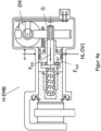
- the Figure 4a shows a cross-sectional view through a hydraulically assisted electromechanical brake H-EMB, which can be connected to the pressure supply device DV1 via a hydraulic connection HL-DV1, so that a force can be applied to the brake discs either via the hydraulic system and/or the electric motor EM.
- the rotary movement of the electric motor is converted into a linear movement via a gear G and generates the force F EM on the wheel brake.
- the transmission G is preferably designed to be self-locking, so that the parking brake functions reliably when the vehicle is stationary if the vehicle electrical system fails.
- a hydraulic force F hyd is generated via the pressure supply.
- the dynamics of the braking torque change and the additionally available braking torque can be determined by the H-EMB through the appropriate design of the components and can be adjusted to the hydraulic brake.
- the Figure 4b shows a possible valve switching and its function for pressure control in the four wheel brakes RB1 to RB4 according to the valve switching of Figure 3a (only AV implemented on wheel brake RB2, not on RB3).
- the pressure build-up and pressure reduction in the wheel brakes preferably takes place via the pressure supply device DV1 when the switching valves SV1 and SV2 are open in the wheel brakes RB1 and RB2, and via the DV2 when the switching valves SV3 and SV4 are open in the wheel brakes RB3 and RB4.
- Control is either with pressure as a controlled variable, supported by the PPC method, e.g. by suitable pilot control, or if a pressure sensor is not available exclusively by the PPC method.
- the pressure of the wheel brake RB2 can be released into the reservoir VB via the outlet valve AV, eg by PWM control of the AV valve, in which case AV is open and SV2 is closed.
- pressure can be built up in RB1 via DV1 by opening switching valve SV1.
- a combination of the PPC method with the PWM control is also a possible control method.
- both switching valves SV1 and SV2 are opened or one switching valve or both switching valves are clocked using the PWM method and outlet valve AV is either open or is also clocked.
- This method is an alternative to the well-known multiplex method, where switching valves are opened or closed digitally and the pressure is reduced sequentially or simultaneously, and is based on the method in EN102015103858 on.
- the valve circuit can be expanded with additional exhaust valves (1 AV in each case in RB 3 cf. Figure 3a , or AV valves on three or all wheel brakes in all wheel brakes) if further degrees of freedom are required for pressure reduction.
- the switching valves SV1-4 are arranged and designed in such a way that they open automatically as a result of the pressure trapped in the wheel brakes. This ensures that no brake pressure is trapped in the wheel even if the entire system fails.
- the Figure 4c shows an embodiment of an actuating device BE with brake pedal 1, tappet 2, piston 3, cylinder 5 and pedal feel simulator 6 for pressure build-up in one or more brake circuit(s) BK1 or BK2.
- the piston 3, which has three seals D1, D2, D3 in the cylinder 5, is moved to the left by the brake pedal 1 via the tappet 2, whereby a pressure builds up in the pressure chamber 4 or a pressure volume via the hydraulic line HL in the brake circuits BK1/BK2 is promoted.
- redundant seals in the cylinder and parallel hydraulic lines VLDR, VLVB to the reservoir VB are provided between the seals D1, D2, D3, with a hydraulic line VL DR having a throttle DR.
- the failure of a seal D1-D3 can thus be reliably diagnosed and a reliable actuation system with pedal feel simulator and sealing system with multiple redundancy and the possibility of generating pressure in the event of failure of the electromotive pressure supply device is available.
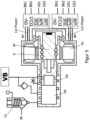
- the figure 5 shows a possible embodiment of a pressure supply device DV1 with two open-loop and closed-loop control devices DV-ECU1 and DV-ECU2.
- the pressure supply device has an electric motor M1, the rotor R of which adjusts a spindle SP, which is connected to a piston KB.
- a pressure can be built up in the pressure chamber DR, which via the isolating valve TV in a brake circuit BK can be directed.
- the piston is sealed by a number of redundant seals in the cylinder, with a redundant diagnosable sealing system being created as with the actuation unit BE.
- a hydraulic line leads to the reservoir between the seals.
- the pressure supply is still fully operational and redundant even if one seal fails.
- the pressure chamber DR is connected to the reservoir via a non-return valve. This means that the pressure supply can replenish.
- Each of the two control and regulating devices DV-ECU1 and DV-ECU2 are connected via 1x3 phase lines to separate windings or phase systems of motor M1, so that if one control and regulating device or winding system fails, motor M1 still has the other winding or phase system and the other open-loop and closed-loop control device can be operated, even if only approximately half the torque can then be generated by means of the drive M1.
- One or both control and regulating device(s) has or have sensors for determining the temperature T, the motor current i and the rotor angle of the electric motor a.
- the control and regulating devices DV-ECU designed redundantly, but power supplies BN1, BN2 and data and control lines DS1 and DS2 are also provided in duplicate.
- the power supplies BN1 and BN2 can be, for example, different voltage levels of a vehicle electrical system or separate vehicle electrical systems.
- the Figure 6a shows torque diagrams to show the brake power assistance using hydraulically assisted electromechanical brakes H-EMB and traction motor TM.
- the diagram on the left shows the torque curve M hyd,DV1 , which can be achieved solely by means of the pressure supply device DV1.
- the diagram on the right shows the torque curve that can be achieved by adding the hydraulically assisted electromechanical brake H-EMB and a traction motor TM.
- a maximum torque M max, H-EMB of H-EMB or M max,TM of the traction motor is available.
- the Blocking pressure (horizontal dashed line) is reached earlier by the period of time ⁇ t .
- a significantly greater braking torque can also be generated.
- the Figure 6b shows the possibility of downsizing the pressure supply device DV1, provided that the braking effect of the hydraulically assisted brake (H-EMB) according to Figure 4a included in the pressure control.
- the pressure supply device DV1 should not be reduced in terms of the maximum pressure that can be built up, but in terms of its dynamics, with which the electric motor can be produced more cheaply.
- the Figure 6c shows torque diagrams to show the braking power assistance using a hydraulically assisted electromechanical brake H-EMB and traction motor TM in emergency operation if a winding or phase system 1x3 phases of the drive M1 fails. Due to the omission of a winding system, the pressure supply DV1 can no longer build up the required pressure up to the blocking pressure and is also no longer dynamic enough. By using the hydraulically assisted electromechanical brake H-EMB and the traction motor(s), the required dynamics and the required braking pressure can be built up (diagram on the right).
- the Figure 6d shows torque diagrams to show the braking torque curve M brake during the replenishment of brake fluid. No further brake pressure can be built up by means of the pressure supply device DV1 during the subsequent delivery from the reservoir VB.
- the braking torque M brake can also be further increased during re-conveying, which significantly improves the dynamics of the system.
- the Figure 6e shows a brake pressure control in the event of failure of the pressure transmitter DG, in which case the motor torque M Mot and thus the control of the pressure p are then controlled by measuring the motor current i phase and evaluating the pressure-volume characteristic.
- the motor temperature T is also taken into account, since the torque constant is reduced under temperature and thus has an influence on the proportionality factor kt ⁇ (1-Br% ⁇ ⁇ T) between motor torque M Mot and motor current i phase . This advantageously results in a redundancy of the pressure measurement.
- a pressure transmitter can also be dispensed with.
- the regulation is calibrated by the pressure transmitter and it is primarily regulated with current, displacement and pressure volume characteristic.
- the pressure is also possible for the pressure to be adjusted via the motor current of the drive of the pressure supply device, since the torque of the motor and the motor phase current are proportional to one another.
- the Figure 7a shows a representation of an entire assembly consisting of motor 22, pump Z, HCU and ECU, which is able to exercise the pressure control for hydraulic actuating actuators, in particular hydraulic wheel brakes or hydraulic-electromechanical wheel brakes (H-EMB).
- the main purpose of this is to show the combination of motor and pump.
- the pump is arranged in the bearing flange 18 or is attached to the HCU or ECU in a separate pump housing 40, as shown in the upper half of the figure.
- a version is shown which requires an additional motor bearing 20 in which the shaft 1 is mounted.
- the motor consists of rotor 21, which is connected to shaft 1 via driver 10a.
- the rotor 21 is axially preloaded by its force via a permanent magnet in the housing 30 .
- This is a solution for the motor manufacturer who manufactures the motor with housing 22 and stator and winding 23, tests it and delivers it to the system supplier.
- the engine is tested without a pump with an auxiliary shaft. After that, when the shaft is removed, the rotor is centered by the axial magnetic force, so that the shaft 1 can then be assembled with the rotor during final assembly.
- the drive housing must also be joined and fastened here with the flange 18 at 25a - shown in the lower half of the figure, e.g. B. with springs, which are plugged into segments over three connections.
- a housing seal 31 is also necessary here.
- the motor flange with HCU or ECU can be attached by caulking at 25 the motor flange with HCU or ECU, see upper half of figure 28.
- the pump version with pump housing is shown here.
- the motor is shown here as a brushless motor, which has a motor sensor for commutation and control of the volume flow of the pump needs.
- This motor sensor is arranged at a distance from the drive housing 22, with a sensor shaft 26, which is arranged or fastened to the drive shaft 1, carrying a sensor target 27.
- This target 27 acts on the sensor element 28, which is arranged on the printed circuit board of the ECU.
- the winding is connected to the ECU via contact rails 24.
- the engine with bearing flange 18 can be connected directly to the hydraulic housing HCU, which valves or other hydr. Includes components to be connected to the pump. If this is not the case, then the drive housing 22, 18 can be connected directly to the housing of the ECU.
- the gear pump Z is also possible to arrange the gear pump Z in a pump housing 40, which is connected directly to the hydraulic housing HCU, as shown in Figure 7a is shown in the upper half of the drive shaft 1.
- the gear pump Z is first integrated or assembled in the pump housing 40, with the rotor 21 then being pressed onto the shaft 1 and then assembled with the bearing 20.
- the tensile force of the magnet 30 can also act on the rotor 21 and the bearing 20, so that the bearing acts like a four-point bearing.
- the motor housing 22 is thus connected to the gear pump Z and its pump housing 40 and can be connected to the hydraulic housing HCU or the electronics housing ECU in the next step.
- the fastening screw 41 is used for this.
- the shaft 1 is previously centered in the outer disks 7.1 and 7.2, so that the pump housing 40 is centered with the shaft 1 before it is screwed to the hydraulic housing HCU or the electronics housing ECU.
- the pressure supply device uses a 2-stage pump with long slide or roller bearings, which does not require separate motor bearings. Accordingly, the motor body structure is simplified.
- the rotor 21 sits with driver 10a on the motor shaft and is axially connected to the circlip.
- the pump housing protrudes slightly into the HCU here.
Landscapes
- Engineering & Computer Science (AREA)
- Transportation (AREA)
- Mechanical Engineering (AREA)
- Power Engineering (AREA)
- Physics & Mathematics (AREA)
- Fluid Mechanics (AREA)
- Regulating Braking Force (AREA)
- Valves And Accessory Devices For Braking Systems (AREA)
Priority Applications (1)
| Application Number | Priority Date | Filing Date | Title |
|---|---|---|---|
| EP24189574.7A EP4501721A3 (fr) | 2018-12-20 | 2019-12-20 | Système de freinage redondante avec deux alimentations de pression pour véhicule électrique et véhicule autonome de niveau 3 (had) à 5 (ad) |
Applications Claiming Priority (5)
| Application Number | Priority Date | Filing Date | Title |
|---|---|---|---|
| DE102018133189.4A DE102018133189A1 (de) | 2018-12-20 | 2018-12-20 | Redundantes Bremssystem mit 2 Druckversorgungen für Elektrofahrzeuge und Fahrzeuge mit autonomem Fahren der Stufe 3 (HAD) bis Stufe 5 (AD) |
| DE202019107191.5U DE202019107191U1 (de) | 2019-07-10 | 2019-07-10 | Druckversorgungseinrichtung mit einer Zahnradpumpe |
| DE202019107193.1U DE202019107193U1 (de) | 2019-08-30 | 2019-08-30 | Bremsvorrichtung, insbesondere für elektrisch angetriebene Kraftfahrzeuge |
| PCT/EP2019/086864 WO2020128078A2 (fr) | 2018-12-20 | 2019-12-20 | Système de freinage redondant à deux alimentations en pression pour véhicule électrique et véhicule à conduite autonome du rapport 3 (had) au rapport 5 (ha) |
| EP19831970.9A EP3898357B1 (fr) | 2018-12-20 | 2019-12-20 | Système de freinage redondante avec deux alimentations de pression pour véhicule électrique et véhicule autonome de niveau 3 (had) à 5 (ad) |
Related Parent Applications (1)
| Application Number | Title | Priority Date | Filing Date |
|---|---|---|---|
| EP19831970.9A Division EP3898357B1 (fr) | 2018-12-20 | 2019-12-20 | Système de freinage redondante avec deux alimentations de pression pour véhicule électrique et véhicule autonome de niveau 3 (had) à 5 (ad) |
Related Child Applications (1)
| Application Number | Title | Priority Date | Filing Date |
|---|---|---|---|
| EP24189574.7A Division EP4501721A3 (fr) | 2018-12-20 | 2019-12-20 | Système de freinage redondante avec deux alimentations de pression pour véhicule électrique et véhicule autonome de niveau 3 (had) à 5 (ad) |
Publications (3)
| Publication Number | Publication Date |
|---|---|
| EP4147925A1 true EP4147925A1 (fr) | 2023-03-15 |
| EP4147925C0 EP4147925C0 (fr) | 2024-08-07 |
| EP4147925B1 EP4147925B1 (fr) | 2024-08-07 |
Family
ID=69174443
Family Applications (3)
| Application Number | Title | Priority Date | Filing Date |
|---|---|---|---|
| EP24189574.7A Pending EP4501721A3 (fr) | 2018-12-20 | 2019-12-20 | Système de freinage redondante avec deux alimentations de pression pour véhicule électrique et véhicule autonome de niveau 3 (had) à 5 (ad) |
| EP22198126.9A Active EP4147925B1 (fr) | 2018-12-20 | 2019-12-20 | Système de freinage redondant avec 2 alimentations en pression pour les véhicules électriques et les véhicules à conduite autonome de niveau 3 (had) à niveau 5 (ad) |
| EP19831970.9A Active EP3898357B1 (fr) | 2018-12-20 | 2019-12-20 | Système de freinage redondante avec deux alimentations de pression pour véhicule électrique et véhicule autonome de niveau 3 (had) à 5 (ad) |
Family Applications Before (1)
| Application Number | Title | Priority Date | Filing Date |
|---|---|---|---|
| EP24189574.7A Pending EP4501721A3 (fr) | 2018-12-20 | 2019-12-20 | Système de freinage redondante avec deux alimentations de pression pour véhicule électrique et véhicule autonome de niveau 3 (had) à 5 (ad) |
Family Applications After (1)
| Application Number | Title | Priority Date | Filing Date |
|---|---|---|---|
| EP19831970.9A Active EP3898357B1 (fr) | 2018-12-20 | 2019-12-20 | Système de freinage redondante avec deux alimentations de pression pour véhicule électrique et véhicule autonome de niveau 3 (had) à 5 (ad) |
Country Status (5)
| Country | Link |
|---|---|
| US (2) | US12409823B2 (fr) |
| EP (3) | EP4501721A3 (fr) |
| CN (2) | CN113423622A (fr) |
| DE (1) | DE112019006337A5 (fr) |
| WO (1) | WO2020128078A2 (fr) |
Cited By (1)
| Publication number | Priority date | Publication date | Assignee | Title |
|---|---|---|---|---|
| DE102023207549A1 (de) * | 2023-08-04 | 2025-02-06 | Continental Automotive Technologies GmbH | Bremssystem für ein Kraftfahrzeug mit elektrischem Antrieb |
Families Citing this family (22)
| Publication number | Priority date | Publication date | Assignee | Title |
|---|---|---|---|---|
| DE102017114556A1 (de) | 2017-06-29 | 2019-01-03 | Ipgate Ag | Vorrichtung für ein hydraulisches Betätigungssystem |
| DE102018010168A1 (de) * | 2018-12-28 | 2020-07-02 | Zf Active Safety Gmbh | Hydraulische Kraftfahrzeug-Bremsanlage und Verfahren zum Betreiben derselben |
| DE202019101596U1 (de) | 2019-02-12 | 2020-05-13 | Ipgate Ag | Hydrauliksystem mit mindestens zwei hydraulischen Kreisen und mindestens zwei Druckversorgungseinrichtungen |
| CN113631443B (zh) | 2019-02-12 | 2024-02-23 | 爱皮加特股份公司 | 具有压力供给装置和用于制动回路的安全门的制动系统 |
| DE102019103464A1 (de) | 2019-02-12 | 2020-08-13 | Ipgate Ag | Hydrauliksystem mit mindestens zwei hydraulischen Kreisen und mindestens zwei Druckversorgungseinrichtungen |
| DE202019101586U1 (de) | 2019-02-12 | 2020-05-13 | Ipgate Ag | Packaging für ein Bremssystem |
| JP2022520243A (ja) | 2019-02-12 | 2022-03-29 | アイピーゲート・アクチェンゲゼルシャフト | フェールセーフブレーキシステム |
| US12071118B2 (en) | 2019-02-12 | 2024-08-27 | Ipgate Ag | Pressure supply device with double stroke piston for a brake system |
| JP7078008B2 (ja) * | 2019-04-03 | 2022-05-31 | トヨタ自動車株式会社 | ブレーキ液圧発生装置の支持構造 |
| EP3741634B1 (fr) * | 2019-05-23 | 2022-07-06 | Robert Bosch GmbH | Contrôle de frein de parking électrique réparti |
| DE102019123343A1 (de) * | 2019-08-30 | 2021-03-04 | Ipgate Ag | Bremsvorrichtung, insbesondere für elektrisch angetriebene Kraftfahrzeuge |
| DE102021100921A1 (de) | 2021-01-18 | 2022-07-21 | Audi Aktiengesellschaft | Elektrohydraulischer Achsmomentensteller |
| KR20220159552A (ko) * | 2021-05-25 | 2022-12-05 | 현대모비스 주식회사 | 브레이크 시스템의 펌프하우징 레이아웃 |
| JP7655826B2 (ja) * | 2021-09-09 | 2025-04-02 | 日立Astemo株式会社 | ブレーキ装置 |
| CN115848338A (zh) * | 2021-09-23 | 2023-03-28 | 大陆汽车科技有限公司 | 制动系统和方法 |
| KR20230065815A (ko) * | 2021-11-05 | 2023-05-12 | 현대모비스 주식회사 | 전자식 유압 브레이크 |
| DE102021215001A1 (de) * | 2021-12-23 | 2023-06-29 | Robert Bosch Gesellschaft mit beschränkter Haftung | Bremssystem für ein Elektrofahrzeug, Elektrofahrzeug und Verfahren zum Betreiben eines Bremssystems in einem Elektrofahrzeug |
| EP4554827B1 (fr) * | 2022-07-12 | 2026-04-01 | Stellantis Europe S.p.A. | Système et procédé de génération de pression hydraulique pour actionner un système de freinage de véhicule automobile |
| CN115648969B (zh) * | 2022-11-09 | 2025-06-10 | 北汽福田汽车股份有限公司 | 车辆控制方法、装置、存储介质、电子设备及车辆 |
| CN116039587B (zh) * | 2023-03-30 | 2023-06-20 | 小米汽车科技有限公司 | 制动控制方法、装置、系统、车辆、介质及芯片 |
| US20240359674A1 (en) * | 2023-04-25 | 2024-10-31 | ZF Active Safety US Inc. | Brake system apparatuses, methods, and arrangements |
| CN118220090A (zh) * | 2024-04-25 | 2024-06-21 | 比博斯特(北京)汽车科技有限公司 | 一种电子机械制动冗余系统及车辆 |
Citations (17)
| Publication number | Priority date | Publication date | Assignee | Title |
|---|---|---|---|---|
| DE4335769C1 (de) * | 1993-10-20 | 1994-12-08 | Daimler Benz Ag | Bremsdruck-Steuereinrichtung für ein Straßenfahrzeug |
| DE102007015809A1 (de) | 2007-03-30 | 2008-10-02 | Ipgate Ag | Elektrische Parkierbremse |
| US7872389B2 (en) | 2005-08-25 | 2011-01-18 | Ipgate Ag | Electric drive having a bell-shaped armature and external permanent magnet elements |
| AT12010U2 (de) * | 2011-04-04 | 2011-09-15 | Ve Vienna Engineering Forschungs Und Entwicklungs Gmbh | Elektrofahrzeug mit radindividuellen reibungsbremsen und radindividuellem antrieb und bremsverfahren dafür |
| US20110241417A1 (en) * | 2009-11-20 | 2011-10-06 | Toyota Jidosha Kabushiki Kaisha | Braking apparatus |
| WO2012059175A1 (fr) | 2010-11-03 | 2012-05-10 | Ipgate Ag | Dispositif d'actionnement, en particulier pour un système de freinage de véhicule |
| EP1874602B1 (fr) | 2005-04-21 | 2012-12-05 | Ipgate Ag | Commande de modulateur de pression |
| EP1759447B1 (fr) | 2004-06-23 | 2013-07-10 | Thomas Leiber | Machine a champ tournant pourvue d'induits en cloche |
| EP2396202B1 (fr) | 2009-02-13 | 2015-04-29 | Ipgate Ag | Systeme de freinage avec diminution ou augmentation de pression dans les cylindres de frein simultanee ou partiellement simultanee a partir de niveaux differents de la pression dans les cylindres de frein |
| WO2016014622A1 (fr) | 2014-07-23 | 2016-01-28 | Fci Asia Pte. Ltd | Module connecteur optoélectrique |
| DE102015103858A1 (de) | 2015-03-16 | 2016-09-22 | Ipgate Ag | Verfahren und Vorrichtung zur Druckregelung von elektrohydraulischen Systemen, insbesondere Druckregelverfahren für eine elektrohydraulische Bremsanlage |
| WO2017058707A1 (fr) * | 2015-09-28 | 2017-04-06 | Faraday&Future Inc. | Système et procédé de compensation de la direction |
| DE112009005541B3 (de) | 2009-02-03 | 2017-08-17 | Ipgate Ag | Bremssystem ohne Wegsimulator |
| US20170246957A1 (en) * | 2016-02-25 | 2017-08-31 | Fuji Jukogyo Kabushiki Kaisha | Vehicle control device and vehicle control method |
| EP3271221A2 (fr) | 2015-03-16 | 2018-01-24 | IPGate AG | Système de freinage à régulation mux innovante (mux 2.0) équipé d'une soupape de sortie/ou équipé d'une soupape de sortie par circuit de freinage et procédé servant à la régulation de pression |
| DE102016225537A1 (de) * | 2016-12-20 | 2018-06-21 | Continental Teves Ag & Co. Ohg | Bremssystem mit zwei Druckquellen und Verfahren zum Betreiben eines Bremssystems |
| DE102005018649B4 (de) | 2005-04-21 | 2018-10-31 | Ipgate Ag | Bremssystem mit elektromotorisch angetriebenem Kolben-Zylinder-System |
Family Cites Families (79)
| Publication number | Priority date | Publication date | Assignee | Title |
|---|---|---|---|---|
| DE4413579A1 (de) | 1994-04-19 | 1995-10-26 | Teves Gmbh Alfred | Elektronisch regelbares Bremsbetätigungssystem |
| WO1997039931A1 (fr) * | 1996-04-25 | 1997-10-30 | Lucas Industries Plc | Systemes de freins electro-hydrauliques |
| DE19832167A1 (de) * | 1997-11-22 | 1999-05-27 | Itt Mfg Enterprises Inc | Elektromechanisches Bremssystem |
| JP3896240B2 (ja) * | 2000-03-24 | 2007-03-22 | 住友電工ブレーキシステムズ株式会社 | 回生協調ブレーキシステムの制御方法 |
| US7063393B2 (en) * | 2001-08-22 | 2006-06-20 | Advics Co., Ltd. | Electronic brake system without pump unit |
| DE10236390B4 (de) * | 2002-08-08 | 2014-02-13 | Robert Bosch Gmbh | Hydraulikaggregat für eine Fahrzeugbremsanlage mit Blockierschutzeinrichtung |
| US7409280B2 (en) | 2004-01-15 | 2008-08-05 | Nissan Motor Co., Ltd. | Vehicle braking control apparatus |
| WO2006061433A1 (fr) * | 2004-12-09 | 2006-06-15 | Continental Teves Ag & Co. Ohg | Procede pour commander un systeme de freinage d'un vehicule automobile |
| US8608255B2 (en) * | 2006-04-14 | 2013-12-17 | Toyota Jidosha Kabushiki Kaisha | Vehicle and control method of vehicle |
| DE102007036859A1 (de) * | 2006-08-10 | 2008-04-30 | Continental Teves Ag & Co. Ohg | Fremdansteuerbare elektrohydraulische Fahrzeugbremsanlage |
| DE102008017478A1 (de) | 2007-04-05 | 2008-10-09 | Continental Teves Ag & Co. Ohg | Verfahren zum Betrieb einer Fahrzeugbremsanlage und Fahrzeugbremsanlage |
| DE102008039960A1 (de) * | 2007-09-05 | 2009-03-12 | Continental Teves Ag & Co. Ohg | Bremssystem für ein Kraftfahrzeug |
| DE102008051350A1 (de) | 2007-10-27 | 2009-04-30 | Continental Teves Ag & Co. Ohg | Kombinierte Fahrzeugbremse mit elektromechanisch betätigbarer Feststellbremse |
| JP4623090B2 (ja) * | 2007-12-25 | 2011-02-02 | トヨタ自動車株式会社 | ブレーキ制御装置 |
| DE102009033499A1 (de) * | 2008-07-18 | 2010-01-21 | Continental Teves Ag & Co. Ohg | Bremsanlage für Kraftfahrzeuge |
| DE102009019793A1 (de) | 2009-04-02 | 2010-10-07 | Continental Teves Ag & Co. Ohg | Kombinierte Fahrzeugbremse mit elektromechanisch betätigbarer Feststellbremse |
| JP5216712B2 (ja) * | 2009-07-31 | 2013-06-19 | 本田技研工業株式会社 | 自動二輪車のブレーキ装置 |
| DE102010003076A1 (de) | 2009-08-05 | 2011-08-18 | Continental Automotive GmbH, 30165 | Verfahren zur Regelung eines Radbremsschlupfes und Radbremsschlupfregelsystem für ein Fahrzeug mit einem Elektroantrieb |
| JP5229397B2 (ja) * | 2009-10-28 | 2013-07-03 | トヨタ自動車株式会社 | ブレーキ制御装置 |
| US20120030581A1 (en) | 2010-07-28 | 2012-02-02 | Weiyi Cui | Mashup Component Framework for Business Enterprise User Interfaces |
| DE102010038555B4 (de) * | 2010-07-28 | 2017-01-26 | Robert Bosch Gmbh | Bremssystem für ein Fahrzeug und Verfahren zum Betreiben eines Bremssystems für ein Fahrzeug |
| DE102010041853A1 (de) | 2010-10-01 | 2012-04-05 | Continental Teves Ag & Co. Ohg | Verfahren für die Steuerung eines Kraftfahrzeugbremssystems |
| DE102011084206A1 (de) | 2010-10-12 | 2012-04-12 | Continental Teves Ag & Co. Ohg | Bremsanlage für Kraftfahrzeuge |
| US9376097B2 (en) * | 2010-12-20 | 2016-06-28 | Bosch Corporation | Vehicle brake device and method of controlling the same |
| DE102012205862A1 (de) * | 2011-04-19 | 2012-10-25 | Continental Teves Ag & Co. Ohg | Bremsanlage für Kraftfahrzeuge sowie Verfahren zum Betrieb einer Bremsanlage |
| DE102012205859A1 (de) * | 2011-04-19 | 2012-10-25 | Continental Teves Ag & Co. Ohg | Bremsanlage für Kraftfahrzeuge sowie Verfahren zum Betrieb einer Bremsanlage |
| DE102012205962A1 (de) * | 2011-05-05 | 2012-11-08 | Continental Teves Ag & Co. Ohg | Bremsanlage für Kraftfahrzeuge sowie Verfahren zum Betrieb einer Bremsanlage |
| JP2013010469A (ja) | 2011-06-30 | 2013-01-17 | Hitachi Automotive Systems Ltd | 電動倍力装置 |
| DE102012213216A1 (de) * | 2011-08-15 | 2013-02-21 | Continental Teves Ag & Co. Ohg | Bremsbetätigungseinheit |
| JP2013060031A (ja) * | 2011-09-12 | 2013-04-04 | Hitachi Automotive Systems Ltd | ブレーキ制御装置 |
| KR101359341B1 (ko) | 2012-03-13 | 2014-02-11 | 주식회사 만도 | 통합 전자제어 유압제동 시스템 |
| JP5960461B2 (ja) | 2012-03-21 | 2016-08-02 | トヨタ自動車株式会社 | ブレーキ装置 |
| DE102013204778B4 (de) * | 2012-03-22 | 2026-03-26 | Aumovio Germany Gmbh | Verfahren zur haptischen Information des Fahrers eines Kraftfahrzeugs |
| JP5898035B2 (ja) | 2012-09-28 | 2016-04-06 | 日立オートモティブシステムズ株式会社 | ディスクブレーキ装置 |
| DE102013225809A1 (de) * | 2013-02-27 | 2014-08-28 | Continental Teves Ag & Co. Ohg | Bremsanlage für Kraftfahrzeuge |
| DE102013224313A1 (de) | 2013-03-05 | 2014-09-11 | Continental Teves Ag & Co. Ohg | Verfahren zum Betreiben eines Bremssystems |
| DE102013224870A1 (de) * | 2013-03-05 | 2014-09-11 | Continental Teves Ag & Co. Ohg | Bremsbetätigungseinheit |
| DE102013014173A1 (de) | 2013-08-26 | 2015-02-26 | Lucas Automotive Gmbh | Elektrohydraulische Fahrzeug-Bremsanlage mit elektromechanischem Aktuator und Verfahren zum Betreiben der Bremsanlage |
| DE102013217954A1 (de) | 2013-09-09 | 2015-03-12 | Continental Teves Ag & Co. Ohg | Bremsanlage für ein Kraftfahrzeug und Betriebsverfahren |
| DE102013223859A1 (de) | 2013-11-21 | 2015-05-21 | Continental Teves Ag & Co. Ohg | Bremsanlage für Kraftfahrzeuge |
| DE102013224776A1 (de) | 2013-12-03 | 2015-06-03 | Continental Teves Ag & Co. Ohg | Bremssystem für ein Kraftfahrzeug |
| US9296370B2 (en) * | 2013-12-04 | 2016-03-29 | Continental Automotive Systems, Inc. | Hydraulic and electronic braking system for autonomous braking |
| US10293798B2 (en) | 2014-03-24 | 2019-05-21 | Ford Global Technologies, Llc | Braking system with selective braking backup system |
| DE102015206572A1 (de) * | 2014-05-15 | 2015-11-19 | Continental Teves Ag & Co. Ohg | Bremsanlage für Kraftfahrzeuge |
| US10166964B2 (en) * | 2014-07-10 | 2019-01-01 | Continental Automotive Systems, Inc. | Pedalless electronically controlled hydraulic braking system with redundant pump |
| JP6241616B2 (ja) * | 2014-12-04 | 2017-12-06 | トヨタ自動車株式会社 | 車両用制動力制御装置 |
| US9592802B2 (en) * | 2014-12-10 | 2017-03-14 | Yangzhou Taibo Automotive Electronics Intelligent Technology Company, Ltd | Brake-by-wire system based on dual-motor configuration and operation methods thereof |
| DE102014225958A1 (de) * | 2014-12-16 | 2016-06-16 | Continental Teves Ag & Co. Ohg | Bremsanlage für ein Kraftfahrzeug |
| DE102014225954A1 (de) * | 2014-12-16 | 2016-06-16 | Continental Teves Ag & Co. Ohg | Bremsensteuervorrichtung sowie Bremsanlage |
| DE102016203111A1 (de) * | 2015-03-05 | 2016-09-08 | Continental Teves Ag & Co. Ohg | Bremsanlage für Kraftfahrzeuge |
| WO2016146222A2 (fr) | 2015-03-16 | 2016-09-22 | Ipgate Ag | Système de freinage équipé d'une unité à maître-cylindre de frein à régulation mux innovante (mux 2.0) comprenant au moins une soupape de sortie, et procédé servant à la régulation de pression |
| KR101673772B1 (ko) * | 2015-05-29 | 2016-11-07 | 현대자동차주식회사 | 전자식 유압 브레이크 장치 및 그 제어 방법 |
| DE102015210433A1 (de) | 2015-06-08 | 2016-12-08 | Robert Bosch Gmbh | Verfahren zum Abbremsen eines Fahrzeugs |
| JP6432942B2 (ja) * | 2015-06-23 | 2018-12-05 | 日立オートモティブシステムズ株式会社 | ブレーキ装置 |
| US10569657B2 (en) | 2016-02-16 | 2020-02-25 | Toyota Jidosha Kabushiki Kaisha | Vehicle brake system |
| DE102016203119A1 (de) | 2016-02-26 | 2017-08-31 | Continental Teves Ag & Co. Ohg | Zusatzmodul für eine elektrohydraulische Bremsanlage und Bremsanlagensystem |
| DE102016203563A1 (de) | 2016-03-04 | 2017-09-07 | Continental Teves Ag & Co. Ohg | Bremsanlage mit zwei Druckbereitstellungseinrichtungen sowie Verfahren zum Betreiben einer Bremsanlage |
| DE102016213994A1 (de) | 2016-07-29 | 2018-02-01 | Continental Teves Ag & Co. Ohg | Bremssystem und Verfahren zum Betreiben eines Bremssystems |
| DE102017222445A1 (de) * | 2017-01-11 | 2018-07-12 | Continental Teves Ag & Co. Ohg | Bremsanlage für ein Kraftfahrzeug und Verfahren zum Betrieb einer Bremsanlage |
| DE102017222450A1 (de) | 2017-01-11 | 2018-07-12 | Continental Teves Ag & Co. Ohg | Bremsanlage für ein Kraftfahrzeug |
| DE102017204157A1 (de) | 2017-03-14 | 2018-09-20 | Bayerische Motoren Werke Aktiengesellschaft | Bremsregelsystem einer elektrohydraulischen Bremsanlage |
| DE102017003654A1 (de) | 2017-04-13 | 2018-10-18 | Lucas Automotive Gmbh | Hydraulische Kraftfahrzeug-Bremsanlage und Steuergerätesystem hierfür |
| DE102017207954A1 (de) | 2017-05-11 | 2018-11-15 | Continental Teves Ag & Co. Ohg | Bremssystem und Verfahren zum Betreiben eines solchen Bremssystems |
| DE102017111077A1 (de) | 2017-05-22 | 2018-11-22 | Lsp Innovative Automotive Systems Gmbh | Bremsvorrichtung, insbesondere für elektrisch angetriebene Kraftfahrzeuge |
| DE102017114556A1 (de) | 2017-06-29 | 2019-01-03 | Ipgate Ag | Vorrichtung für ein hydraulisches Betätigungssystem |
| DE102017211953A1 (de) | 2017-07-12 | 2019-01-17 | Continental Teves Ag & Co. Ohg | Bremssystem |
| JP6834839B2 (ja) * | 2017-08-07 | 2021-02-24 | トヨタ自動車株式会社 | 車両用ブレーキシステム |
| CN111094087B (zh) | 2017-09-27 | 2023-03-17 | 日立安斯泰莫株式会社 | 制动装置、车辆控制装置 |
| DE102017220308A1 (de) | 2017-11-15 | 2019-05-16 | Continental Teves Ag & Co. Ohg | Verfahren zum Überprüfen der Funktionalität eines Bremssystems und Bremssystem |
| DE102018202287A1 (de) * | 2018-02-15 | 2019-08-22 | Robert Bosch Gmbh | Elektrohydraulische Fremdkraft-Fahrzeugbremsanlage für ein autonom fahrendes Landfahrzeug |
| DE102018202885A1 (de) | 2018-02-26 | 2019-08-29 | Robert Bosch Gmbh | Mehrkreisiges hydraulisch offenes Bremssystem, insbesondere für ein hochautomatisiertes oder autonomes Fahrzeug |
| CN110466489A (zh) * | 2018-05-09 | 2019-11-19 | 罗伯特·博世有限公司 | 用于自主行驶的地面车辆的电液式助力-车辆制动系统 |
| JP6952014B2 (ja) | 2018-06-13 | 2021-10-20 | 日立Astemo株式会社 | 車両制御装置、車両制御方法、及び車両制御システム |
| US10821949B2 (en) * | 2018-11-07 | 2020-11-03 | Continental Automotive Systems, Inc. | Electronic brake boost on secondary brake system |
| KR102545107B1 (ko) | 2018-12-03 | 2023-06-20 | 현대자동차주식회사 | 친환경 자동차 및 그를 위한 강판 주행 제어 방법 |
| DE102019123343A1 (de) | 2019-08-30 | 2021-03-04 | Ipgate Ag | Bremsvorrichtung, insbesondere für elektrisch angetriebene Kraftfahrzeuge |
| JP7459729B2 (ja) | 2020-09-01 | 2024-04-02 | トヨタ自動車株式会社 | 車両制御装置 |
| JP7658338B2 (ja) | 2022-07-15 | 2025-04-08 | トヨタ自動車株式会社 | 運動マネージャ、車両、車両の制御方法およびプログラム |
| SE547006C2 (en) * | 2022-09-23 | 2025-04-01 | Volvo Truck Corp | Vehicle retardation torque control |
-
2019
- 2019-12-20 EP EP24189574.7A patent/EP4501721A3/fr active Pending
- 2019-12-20 WO PCT/EP2019/086864 patent/WO2020128078A2/fr not_active Ceased
- 2019-12-20 US US17/415,196 patent/US12409823B2/en active Active
- 2019-12-20 EP EP22198126.9A patent/EP4147925B1/fr active Active
- 2019-12-20 DE DE112019006337.5T patent/DE112019006337A5/de active Pending
- 2019-12-20 CN CN201980092234.4A patent/CN113423622A/zh active Pending
- 2019-12-20 CN CN202410328096.8A patent/CN118478853A/zh active Pending
- 2019-12-20 EP EP19831970.9A patent/EP3898357B1/fr active Active
-
2024
- 2024-09-12 US US18/882,980 patent/US20250001989A1/en active Pending
Patent Citations (18)
| Publication number | Priority date | Publication date | Assignee | Title |
|---|---|---|---|---|
| DE4335769C1 (de) * | 1993-10-20 | 1994-12-08 | Daimler Benz Ag | Bremsdruck-Steuereinrichtung für ein Straßenfahrzeug |
| EP1759447B1 (fr) | 2004-06-23 | 2013-07-10 | Thomas Leiber | Machine a champ tournant pourvue d'induits en cloche |
| DE102005018649B4 (de) | 2005-04-21 | 2018-10-31 | Ipgate Ag | Bremssystem mit elektromotorisch angetriebenem Kolben-Zylinder-System |
| DE102005055751B4 (de) | 2005-04-21 | 2018-09-06 | Ipgate Ag | Druckmodulatorsteuerung |
| EP1874602B1 (fr) | 2005-04-21 | 2012-12-05 | Ipgate Ag | Commande de modulateur de pression |
| US7872389B2 (en) | 2005-08-25 | 2011-01-18 | Ipgate Ag | Electric drive having a bell-shaped armature and external permanent magnet elements |
| DE102007015809A1 (de) | 2007-03-30 | 2008-10-02 | Ipgate Ag | Elektrische Parkierbremse |
| DE112009005541B3 (de) | 2009-02-03 | 2017-08-17 | Ipgate Ag | Bremssystem ohne Wegsimulator |
| EP2396202B1 (fr) | 2009-02-13 | 2015-04-29 | Ipgate Ag | Systeme de freinage avec diminution ou augmentation de pression dans les cylindres de frein simultanee ou partiellement simultanee a partir de niveaux differents de la pression dans les cylindres de frein |
| US20110241417A1 (en) * | 2009-11-20 | 2011-10-06 | Toyota Jidosha Kabushiki Kaisha | Braking apparatus |
| WO2012059175A1 (fr) | 2010-11-03 | 2012-05-10 | Ipgate Ag | Dispositif d'actionnement, en particulier pour un système de freinage de véhicule |
| AT12010U2 (de) * | 2011-04-04 | 2011-09-15 | Ve Vienna Engineering Forschungs Und Entwicklungs Gmbh | Elektrofahrzeug mit radindividuellen reibungsbremsen und radindividuellem antrieb und bremsverfahren dafür |
| WO2016014622A1 (fr) | 2014-07-23 | 2016-01-28 | Fci Asia Pte. Ltd | Module connecteur optoélectrique |
| DE102015103858A1 (de) | 2015-03-16 | 2016-09-22 | Ipgate Ag | Verfahren und Vorrichtung zur Druckregelung von elektrohydraulischen Systemen, insbesondere Druckregelverfahren für eine elektrohydraulische Bremsanlage |
| EP3271221A2 (fr) | 2015-03-16 | 2018-01-24 | IPGate AG | Système de freinage à régulation mux innovante (mux 2.0) équipé d'une soupape de sortie/ou équipé d'une soupape de sortie par circuit de freinage et procédé servant à la régulation de pression |
| WO2017058707A1 (fr) * | 2015-09-28 | 2017-04-06 | Faraday&Future Inc. | Système et procédé de compensation de la direction |
| US20170246957A1 (en) * | 2016-02-25 | 2017-08-31 | Fuji Jukogyo Kabushiki Kaisha | Vehicle control device and vehicle control method |
| DE102016225537A1 (de) * | 2016-12-20 | 2018-06-21 | Continental Teves Ag & Co. Ohg | Bremssystem mit zwei Druckquellen und Verfahren zum Betreiben eines Bremssystems |
Cited By (1)
| Publication number | Priority date | Publication date | Assignee | Title |
|---|---|---|---|---|
| DE102023207549A1 (de) * | 2023-08-04 | 2025-02-06 | Continental Automotive Technologies GmbH | Bremssystem für ein Kraftfahrzeug mit elektrischem Antrieb |
Also Published As
| Publication number | Publication date |
|---|---|
| EP3898357B1 (fr) | 2022-09-28 |
| EP4501721A3 (fr) | 2025-02-19 |
| CN118478853A (zh) | 2024-08-13 |
| EP4147925C0 (fr) | 2024-08-07 |
| US20250001989A1 (en) | 2025-01-02 |
| US20220041150A1 (en) | 2022-02-10 |
| US12409823B2 (en) | 2025-09-09 |
| WO2020128078A3 (fr) | 2020-08-13 |
| EP4501721A2 (fr) | 2025-02-05 |
| CN113423622A (zh) | 2021-09-21 |
| DE112019006337A5 (de) | 2021-09-09 |
| WO2020128078A2 (fr) | 2020-06-25 |
| EP4147925B1 (fr) | 2024-08-07 |
| EP3898357A2 (fr) | 2021-10-27 |
Similar Documents
| Publication | Publication Date | Title |
|---|---|---|
| EP4147925B1 (fr) | Système de freinage redondant avec 2 alimentations en pression pour les véhicules électriques et les véhicules à conduite autonome de niveau 3 (had) à niveau 5 (ad) | |
| EP4219255B1 (fr) | Système de freinage redondant avec une alimentation en pression pour les véhicules électriques et les véhicules à conduite autonome de niveau 3 (had) à niveau 4 (fad) | |
| EP3898359B1 (fr) | Essieu de véhicule avec propulsion électrique, frein électro-hydraulique et modules additionnels comme engrenage, vecteur de couple, et frein de stationnement | |
| EP4021771B1 (fr) | Système pour la dynamique de véhicule | |
| EP3924227B1 (fr) | Système hydraulique muni d'au moins deux circuits hydrauliques et d'au moins deux dispositifs d'alimentation en pression | |
| DE112018008293B4 (de) | Vorrichtung für ein hydraulisches Betätigungssystem | |
| EP4096977B1 (fr) | Système de freinage et procédé de commande d'un système de freinage | |
| DE102018133189A1 (de) | Redundantes Bremssystem mit 2 Druckversorgungen für Elektrofahrzeuge und Fahrzeuge mit autonomem Fahren der Stufe 3 (HAD) bis Stufe 5 (AD) | |
| DE102018133218A1 (de) | Redundantes Bremssystem mit einer Druckversorgung für E-Fahrzeuge und Fahrzeuge mit autonomem Fahren der Stufe 3 (HAD) bis Stufe 4 (FAD) | |
| DE202019107193U1 (de) | Bremsvorrichtung, insbesondere für elektrisch angetriebene Kraftfahrzeuge | |
| DE102022204955A1 (de) | Bremssystem für Kraftfahrzeuge mit einem Aktuator |
Legal Events
| Date | Code | Title | Description |
|---|---|---|---|
| PUAI | Public reference made under article 153(3) epc to a published international application that has entered the european phase |
Free format text: ORIGINAL CODE: 0009012 |
|
| STAA | Information on the status of an ep patent application or granted ep patent |
Free format text: STATUS: REQUEST FOR EXAMINATION WAS MADE |
|
| 17P | Request for examination filed |
Effective date: 20221010 |
|
| AC | Divisional application: reference to earlier application |
Ref document number: 3898357 Country of ref document: EP Kind code of ref document: P |
|
| AK | Designated contracting states |
Kind code of ref document: A1 Designated state(s): AL AT BE BG CH CY CZ DE DK EE ES FI FR GB GR HR HU IE IS IT LI LT LU LV MC MK MT NL NO PL PT RO RS SE SI SK SM TR |
|
| RAP3 | Party data changed (applicant data changed or rights of an application transferred) |
Owner name: IPGATE AG |
|
| GRAP | Despatch of communication of intention to grant a patent |
Free format text: ORIGINAL CODE: EPIDOSNIGR1 |
|
| STAA | Information on the status of an ep patent application or granted ep patent |
Free format text: STATUS: GRANT OF PATENT IS INTENDED |
|
| INTG | Intention to grant announced |
Effective date: 20240305 |
|
| RIN1 | Information on inventor provided before grant (corrected) |
Inventor name: LEIBER, THOMAS |
|
| GRAS | Grant fee paid |
Free format text: ORIGINAL CODE: EPIDOSNIGR3 |
|
| GRAA | (expected) grant |
Free format text: ORIGINAL CODE: 0009210 |
|
| STAA | Information on the status of an ep patent application or granted ep patent |
Free format text: STATUS: THE PATENT HAS BEEN GRANTED |
|
| AC | Divisional application: reference to earlier application |
Ref document number: 3898357 Country of ref document: EP Kind code of ref document: P |
|
| AK | Designated contracting states |
Kind code of ref document: B1 Designated state(s): AL AT BE BG CH CY CZ DE DK EE ES FI FR GB GR HR HU IE IS IT LI LT LU LV MC MK MT NL NO PL PT RO RS SE SI SK SM TR |
|
| REG | Reference to a national code |
Ref country code: GB Ref legal event code: FG4D Free format text: NOT ENGLISH |
|
| REG | Reference to a national code |
Ref country code: CH Ref legal event code: EP |
|
| REG | Reference to a national code |
Ref country code: IE Ref legal event code: FG4D Free format text: LANGUAGE OF EP DOCUMENT: GERMAN |
|
| REG | Reference to a national code |
Ref country code: DE Ref legal event code: R096 Ref document number: 502019011863 Country of ref document: DE |
|
| U01 | Request for unitary effect filed |
Effective date: 20240902 |
|
| U07 | Unitary effect registered |
Designated state(s): AT BE BG DE DK EE FI FR IT LT LU LV MT NL PT RO SE SI Effective date: 20240906 |
|
| PG25 | Lapsed in a contracting state [announced via postgrant information from national office to epo] |
Ref country code: NO Free format text: LAPSE BECAUSE OF FAILURE TO SUBMIT A TRANSLATION OF THE DESCRIPTION OR TO PAY THE FEE WITHIN THE PRESCRIBED TIME-LIMIT Effective date: 20241107 |
|
| PG25 | Lapsed in a contracting state [announced via postgrant information from national office to epo] |
Ref country code: GR Free format text: LAPSE BECAUSE OF FAILURE TO SUBMIT A TRANSLATION OF THE DESCRIPTION OR TO PAY THE FEE WITHIN THE PRESCRIBED TIME-LIMIT Effective date: 20241108 Ref country code: PL Free format text: LAPSE BECAUSE OF FAILURE TO SUBMIT A TRANSLATION OF THE DESCRIPTION OR TO PAY THE FEE WITHIN THE PRESCRIBED TIME-LIMIT Effective date: 20240807 |
|
| PG25 | Lapsed in a contracting state [announced via postgrant information from national office to epo] |
Ref country code: IS Free format text: LAPSE BECAUSE OF FAILURE TO SUBMIT A TRANSLATION OF THE DESCRIPTION OR TO PAY THE FEE WITHIN THE PRESCRIBED TIME-LIMIT Effective date: 20241207 |
|
| PG25 | Lapsed in a contracting state [announced via postgrant information from national office to epo] |
Ref country code: HR Free format text: LAPSE BECAUSE OF FAILURE TO SUBMIT A TRANSLATION OF THE DESCRIPTION OR TO PAY THE FEE WITHIN THE PRESCRIBED TIME-LIMIT Effective date: 20240807 |
|
| PG25 | Lapsed in a contracting state [announced via postgrant information from national office to epo] |
Ref country code: ES Free format text: LAPSE BECAUSE OF FAILURE TO SUBMIT A TRANSLATION OF THE DESCRIPTION OR TO PAY THE FEE WITHIN THE PRESCRIBED TIME-LIMIT Effective date: 20240807 Ref country code: RS Free format text: LAPSE BECAUSE OF FAILURE TO SUBMIT A TRANSLATION OF THE DESCRIPTION OR TO PAY THE FEE WITHIN THE PRESCRIBED TIME-LIMIT Effective date: 20241107 |
|
| PG25 | Lapsed in a contracting state [announced via postgrant information from national office to epo] |
Ref country code: RS Free format text: LAPSE BECAUSE OF FAILURE TO SUBMIT A TRANSLATION OF THE DESCRIPTION OR TO PAY THE FEE WITHIN THE PRESCRIBED TIME-LIMIT Effective date: 20241107 Ref country code: PL Free format text: LAPSE BECAUSE OF FAILURE TO SUBMIT A TRANSLATION OF THE DESCRIPTION OR TO PAY THE FEE WITHIN THE PRESCRIBED TIME-LIMIT Effective date: 20240807 Ref country code: NO Free format text: LAPSE BECAUSE OF FAILURE TO SUBMIT A TRANSLATION OF THE DESCRIPTION OR TO PAY THE FEE WITHIN THE PRESCRIBED TIME-LIMIT Effective date: 20241107 Ref country code: IS Free format text: LAPSE BECAUSE OF FAILURE TO SUBMIT A TRANSLATION OF THE DESCRIPTION OR TO PAY THE FEE WITHIN THE PRESCRIBED TIME-LIMIT Effective date: 20241207 Ref country code: HR Free format text: LAPSE BECAUSE OF FAILURE TO SUBMIT A TRANSLATION OF THE DESCRIPTION OR TO PAY THE FEE WITHIN THE PRESCRIBED TIME-LIMIT Effective date: 20240807 Ref country code: GR Free format text: LAPSE BECAUSE OF FAILURE TO SUBMIT A TRANSLATION OF THE DESCRIPTION OR TO PAY THE FEE WITHIN THE PRESCRIBED TIME-LIMIT Effective date: 20241108 Ref country code: ES Free format text: LAPSE BECAUSE OF FAILURE TO SUBMIT A TRANSLATION OF THE DESCRIPTION OR TO PAY THE FEE WITHIN THE PRESCRIBED TIME-LIMIT Effective date: 20240807 |
|
| U20 | Renewal fee for the european patent with unitary effect paid |
Year of fee payment: 6 Effective date: 20241227 |
|
| PG25 | Lapsed in a contracting state [announced via postgrant information from national office to epo] |
Ref country code: SM Free format text: LAPSE BECAUSE OF FAILURE TO SUBMIT A TRANSLATION OF THE DESCRIPTION OR TO PAY THE FEE WITHIN THE PRESCRIBED TIME-LIMIT Effective date: 20240807 |
|
| PG25 | Lapsed in a contracting state [announced via postgrant information from national office to epo] |
Ref country code: CZ Free format text: LAPSE BECAUSE OF FAILURE TO SUBMIT A TRANSLATION OF THE DESCRIPTION OR TO PAY THE FEE WITHIN THE PRESCRIBED TIME-LIMIT Effective date: 20240807 |
|
| PG25 | Lapsed in a contracting state [announced via postgrant information from national office to epo] |
Ref country code: SK Free format text: LAPSE BECAUSE OF FAILURE TO SUBMIT A TRANSLATION OF THE DESCRIPTION OR TO PAY THE FEE WITHIN THE PRESCRIBED TIME-LIMIT Effective date: 20240807 |
|
| PLBE | No opposition filed within time limit |
Free format text: ORIGINAL CODE: 0009261 |
|
| STAA | Information on the status of an ep patent application or granted ep patent |
Free format text: STATUS: NO OPPOSITION FILED WITHIN TIME LIMIT |
|
| PG25 | Lapsed in a contracting state [announced via postgrant information from national office to epo] |
Ref country code: MC Free format text: LAPSE BECAUSE OF FAILURE TO SUBMIT A TRANSLATION OF THE DESCRIPTION OR TO PAY THE FEE WITHIN THE PRESCRIBED TIME-LIMIT Effective date: 20240807 |
|
| 26N | No opposition filed |
Effective date: 20250508 |
|
| REG | Reference to a national code |
Ref country code: CH Ref legal event code: PL |
|
| PG25 | Lapsed in a contracting state [announced via postgrant information from national office to epo] |
Ref country code: CH Free format text: LAPSE BECAUSE OF NON-PAYMENT OF DUE FEES Effective date: 20241231 |
|
| PG25 | Lapsed in a contracting state [announced via postgrant information from national office to epo] |
Ref country code: IE Free format text: LAPSE BECAUSE OF NON-PAYMENT OF DUE FEES Effective date: 20241220 |
|
| PGFP | Annual fee paid to national office [announced via postgrant information from national office to epo] |
Ref country code: GB Payment date: 20251219 Year of fee payment: 7 |
|
| U20 | Renewal fee for the european patent with unitary effect paid |
Year of fee payment: 7 Effective date: 20251230 |