EP4148015B1 - Étrier de sécurité avec agencement de libération flexible - Google Patents
Étrier de sécurité avec agencement de libération flexible Download PDFInfo
- Publication number
- EP4148015B1 EP4148015B1 EP22194406.9A EP22194406A EP4148015B1 EP 4148015 B1 EP4148015 B1 EP 4148015B1 EP 22194406 A EP22194406 A EP 22194406A EP 4148015 B1 EP4148015 B1 EP 4148015B1
- Authority
- EP
- European Patent Office
- Prior art keywords
- side piece
- flexible side
- stirrup
- protrusion
- open
- Prior art date
- Legal status (The legal status is an assumption and is not a legal conclusion. Google has not performed a legal analysis and makes no representation as to the accuracy of the status listed.)
- Active
Links
Images


Classifications
-
- B—PERFORMING OPERATIONS; TRANSPORTING
- B68—SADDLERY; UPHOLSTERY
- B68C—SADDLES; STIRRUPS
- B68C3/00—Stirrups
- B68C3/02—Stirrups with side part or sole plate attached to other parts of the stirrup movably, e.g. pivotally
-
- B—PERFORMING OPERATIONS; TRANSPORTING
- B68—SADDLERY; UPHOLSTERY
- B68C—SADDLES; STIRRUPS
- B68C3/00—Stirrups
- B68C2003/005—Foot release mechanisms
-
- B—PERFORMING OPERATIONS; TRANSPORTING
- B68—SADDLERY; UPHOLSTERY
- B68C—SADDLES; STIRRUPS
- B68C3/00—Stirrups
- B68C2003/005—Foot release mechanisms
- B68C2003/0066—Foot release mechanisms with fully detachable parts
-
- B—PERFORMING OPERATIONS; TRANSPORTING
- B68—SADDLERY; UPHOLSTERY
- B68C—SADDLES; STIRRUPS
- B68C3/00—Stirrups
-
- B—PERFORMING OPERATIONS; TRANSPORTING
- B68—SADDLERY; UPHOLSTERY
- B68C—SADDLES; STIRRUPS
- B68C3/00—Stirrups
- B68C3/0016—One-legged stirrups
Definitions
- the present invention relates to a safety stirrup for horseback riding.
- Conventional solutions include safety stirrups with flexible or hinged safety release mechanisms, such as the ones disclosed in EP2438003B1 and EP3445708B1 , or more complex mechanisms such as the one disclosed in EP3235779B1 .
- a problem with the former two solutions is that the safety stirrup may not always release as intended, leading to the user being stuck with their foot in the stirrup as they fall down.
- a problem with the latter solution is its complexity, with several components that may be damaged or caused to malfunction due to dirt or debris entering the mechanism.
- the present invention is at least partially based on the realisation that presently available safety stirrups run the risk of malfunctioning due to debris or dirt in the safety mechanism. Having a more simple design of a safety stirrup which more reliably performs its function is beneficial as it increases overall rider safety.
- a safety stirrup for use in horseback riding as defined in claim 1, is provided.
- the safety stirrup comprises an open stirrup body having a tread portion and a stirrup leather connecting portion, and an opening that is defined by the space between a first end and a second end of the open stirrup body.
- the open stirrup body being a stirrup body that does not form a full loop around a boot of a user when in use.
- the safety stirrup further comprises a flexible side piece arranged to bridge the opening between the first end and the second end of the open stirrup body.
- a first end of the flexible side piece and the first end of the open stirrup body are provided with a first protrusion-recess pair for releasably connecting the first end of the flexible side piece to the first end of the open stirrup body.
- a second end of the flexible side piece and the second end of the open stirrup body are provided with means for connecting the second end of the flexible side piece to the second end of the open stirrup body.
- the protrusion of the first protrusion-recess pair has a neck and a head. The head may be formed as an axial extension of the neck in a longitudinal direction of the protrusion.
- the recess of the first protrusion-recess pair has an opening and a cavity, wherein the cavity is shaped to house the head, and wherein the opening is shaped to allow the head to pass therethrough when the first end of the flexible side piece is in a first rotational position relative to the open stirrup body, but not when it is in a second rotational position.
- the tread portion is either a portion to which a tread surface may be connected, or a tread surface integrally formed with the open stirrup body.
- the stirrup leather connecting portion is the portion to which the stirrup leather is to be connected.
- the stirrup leather connection portion comprises, in exemplary embodiments, stirrup leather connection means in the shape of a through-hole, through which the stirrup leather is threaded.
- the tread portion is located opposite the stirrup leather connecting portion and in exemplary embodiments, comprises means for connecting a tread surface thereto.
- An open stirrup body is a stirrup body that does not form a full loop around the boot of a user when in use. Typically, an open stirrup body is open on one side.
- the opening is arranged between the tread portion and the stirrup leather connecting portion.
- the opening is arranged on a lateral side of the open stirrup body.
- the open stirrup body is shaped like an open loop, and wherein the flexible side piece is shaped such that it jointly defines, together with the open stirrup body, a closed loop.
- the means for connecting the second end of the flexible side piece to the second end of the open stirrup body is a second protrusion-recess pair.
- the means for connecting the second end of the flexible side piece to the second end of the open stirrup body is a fixed protrusion-recess pair, in which a portion of the second end of the flexible side piece has been formed inside of the recess of the second end of the open stirrup body.
- the means for connecting the second end of the flexible side piece to the second end of the open stirrup body is a second protrusion-recess pair for releasably connecting the second end of the flexible side piece to the second end of the open stirrup body.
- the protrusion of the second protrusion-recess pair has a neck and a head and the recess of the second protrusion-recess pair has an opening and a cavity.
- the cavity is shaped to house the head, and the opening is shaped to allow the head to pass therethrough when the second end of the flexible side piece is in a first rotational position relative to the open stirrup body, but not when it is in a second rotational position.
- a first and a second end of the flexible side piece and a first and a second end of the open stirrup body are each provided with a respective protrusion-recess pair for releasably connecting the ends of the flexible side piece to the ends of the open stirrup body.
- the protrusions of the protrusion-recess pairs each have a neck and a head.
- the recesses of the protrusion-recess pairs each have an opening and a cavity, wherein the cavity is shaped to house the head, and wherein the opening is shaped to allow the head to pass therethrough when the corresponding end of the flexible side piece is in a first rotational position relative to the open stirrup body, but not when it is in a second rotational position.
- the neck is shaped to allow the head to be inserted through the opening and to be housed inside the cavity.
- the neck does this by being longer than the depth of the opening, such that the head may be rotated to the first rotational position to allow insertion therethrough, and then rotated once again to the second rotational position when inside the cavity to lock the flexible side piece in place relative to the open stirrup body.
- the head is rotatable from the first rotational position to the second rotational position when housed inside the cavity.
- the head is rotatable relative the cavity when housed therein, around the axial extension of the neck/protrusion / the longitudinal axis of the protrusion.
- the opening being shaped to allow the head to pass therethrough when the corresponding end of the flexible side piece is in a first rotational position relative to the open stirrup body, but not when it is in a second rotational position may be expressed as the protrusion-recess pair being configured and/or arranged such that disengagement in a second rotational position is prevented unless a predetermined threshold force is applied thereto, causing at least a portion of the protrusion-recess pair to elastically deform causing disengagement of the flexible side piece from the open stirrup body.
- the opening is shaped to allow the head to pass therethrough when the corresponding end of the flexible side piece is in a first rotational position relative to the open stirrup body.
- the cavity may be formed as an axial extension of the opening, wherein the head is allowed to pass through the opening in a first rotational position but not in a second rotational position, wherein the head is rotatable to the first second rotational position when housed inside the cavity, thereby locking the head within the cavity.
- the recess may be dimensioned so that the head of the protrusion has to pass the opening prior to being housed within the cavity.
- the head of each protrusion is shorter, as measured along a longitudinal direction of the protrusion, than the cavity in which it is to be housed.
- This in combination with the neck being longer than the depth of the opening, allows the protrusion-recess pairs a certain degree of flexibility in longitudinal positioning. This is beneficial as the open stirrup body may flex and elastically deform due to forces it is subjected to during normal use. Having tolerance in the longitudinal direction in the protrusion-recess pairs prevents unintentional disengagement of the flexible side piece from the open stirrup body.
- the referenced rotational positions are to be understood as being positions achieved by rotation of the entire flexible side member about a longitudinal axis of the protrusion-recess pair, or about a longitudinal axis of the neck of the protrusion.
- the rotational positions may refer to positions achieved by flexible twisting deformation of the flexible side piece, such that only a portion thereof rotates about the longitudinal axis.
- the entire flexible side piece may be rotated to allow the connection of the first end of the flexible side piece to the first end of the open stirrup body, and once connected, a portion of the flexible side piece may be subjected to flexible twisting deformation so that the second end thereof may be connected to the second end of the open stirrup body.
- the opening being shaped to allow the head to pass therethrough when the first end of the flexible side piece is in a first rotational position relative to the open stirrup body, but not when it is in a second rotational position, should be understood as meaning that the flexible side piece is kept connected to the open stirrup body for as long as the connection therebetween is not subjected to a force exceeding a given threshold, or until the flexible side piece is moved to its first rotational position.
- passage of head through the opening is prevented up to a predetermined threshold force is applied to the flexible side piece.
- the predetermined threshold force required to disconnect the flexible side piece from the open stirrup body is chosen to be greater than the forces typically applied thereto during normal use of the safety stirrup, but less than what can be expected when a rider falls of the horse and whose foot becomes tangled in the stirrup. Thus, a safety stirrup is achieved.
- Factors affecting the predetermined threshold force required to disengage the flexible side piece from the open stirrup body include the stiffness of the flexible side piece material, the tolerances in the protrusion-recess pair arranged to connect the two, and the shape and size of the protrusion and recess.
- the flexible side piece comprises at least one of the protrusions of the protrusion-recess pairs, wherein the protrusion extends from at least a first end thereof and the open stirrup body having at least one of the recesses of the protrusion-recess pairs, wherein the recess is arranged at least at the first end thereof.
- the at least one protrusion of the flexible side piece is arranged to be releasably connected to the at least one recess of the open stirrup body.
- the aforementioned at least one recess may be arranged on the flexible side member and the aforementioned at least one protrusion on the open stirrup body.
- the neck has a cross-sectional area that is smaller than that of the head, as seen perpendicularly to an axial direction thereof.
- the flexible side piece is shaped (when in a relaxed position in which no elastic deformation is experienced thereby) such that it jointly defines, together with the open stirrup body, a closed loop when the flexible side piece is in the second rotational position, and such that it does not define a closed loop when the flexible side piece is in the first rotational position.
- the flexible side piece may refer to the first end of the flexible side piece.
- the curvature of the flexible side piece completes the loop partially defined by the open stirrup body only when the flexible side piece is connected thereto and is arranged in the second rotational position.
- a normal of an end surface of at least one of the first end and the second end of the open stirrup body is angled relative to the longitudinal extension of the portion of the protrusion-recess pair that is arranged there.
- the end surface is angled relative to the extension of the protrusion extending therefrom.
- the flexible side piece is made of an elastomer.
- This elastomer may for example be silicon, rubber, or another similarly flexible material.
- a mid-section of the flexible side piece has a stiffness that is greater than the stiffness of the first end and second end of the flexible side piece. This increases the reliability of the safety stirrup by reducing the risk of the mid-section of the flexible side piece unintentionally deforming during normal use thereof. Instead, the varying stiffness is such that the ends of the flexible side piece are more likely to deform and release the protrusion-recess pair connection formed between the flexible side piece and the open stirrup body, and only once a certain threshold force has been applied thereto.
- the head of the protrusion of each protrusion-recess pair is T-shaped, triangle shaped, or has lateral protrusions distributed about its circumference.
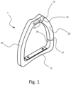
- Figure 1 is a perspective view of a safety stirrup 1 according to the present invention.
- Figure 2 is a side section view of the safety stirrup 1 and two cross-sectional views A-A and B-B thereof.
- Figure 3 is a perspective view of the open stirrup body 10 of the safety stirrup 1, along with a section view C-C of one end of the open stirrup body 10.
- the safety stirrup 1 comprises an open stirrup body 10 having a tread portion 11 and a stirrup leather connecting portion 12, and an opening 13 that is defined by the space between a first end 14 and a second end 15 of the open stirrup body 10.
- the tread portion is the portion of the open stirrup body 10 that is configured such that a tread surface may be connected thereto, while the stirrup leather connecting portion is the portion of the open stirrup body 10 to which the stirrup leather is to be connected when the safety stirrup is in use in horseback riding.
- the stirrup leather connection portion comprises a through-hole, through which the stirrup leather is to be thread.
- the tread portion is located opposite the stirrup leather connecting portion, i.e. in the lower portion of the safety stirrup.
- the open stirrup body 10 is shaped such that it does not itself form a full loop around the boot of a user when in use. Typically, and in the illustrated embodiment, the open stirrup body 10 is open on one side.
- the opening is arranged between the tread portion and the stirrup leather connecting portion, on a lateral side of the open stirrup body 10.
- the safety stirrup 1 further comprises a flexible side piece 20 made from an elastomer, the flexible side piece 20 having a first end 24 and a second end 25 and extending in a direction between the two ends 14, 15 of the open stirrup body 10 in order to bridge the opening therebetween. While the open stirrup body 10 is shaped like an open loop, i.e. C-shaped, the flexible side piece 20 is shaped such that it jointly defines a closed loop together with the open stirrup body 10 when connected thereto.
- the closed loop defined by the open stirrup body 10 and the flexible side piece 20 is defined when the flexible side piece 20 is rotated such that the first end 24 thereof connects to the first end 14 of the open stirrup body 10, and such that the second end 25 thereof connects to the second end 15 of the open stirrup body 10.
- the first 24 and a second end 25 of the flexible side piece 20 and the first 14 and a second end 15 of the open stirrup body 10 are each provided with a respective protrusion-recess pair 30, 40 for releasably connecting the ends 24, 25 of the flexible side piece 20 to the ends 14, 15 of the open stirrup body 10.
- the protrusions 31, 41 of the protrusion-recess pairs 30, 40 each have a neck 32, 42 and a head 33, 43.
- the recesses 34, 44 of the protrusion-recess pairs 30, 40 each have an opening 35, 45 and a cavity 36, 46, wherein the cavity 36, 46 is shaped to house the head 33, 43, and wherein the opening 35, 45 is shaped to allow the head 33, 43 to pass therethrough when the corresponding end 24, 25 of the flexible side piece 20 is in a first rotational position relative to the open stirrup body 10, but not when it is in a second rotational position.
- the head 33, 43 of the protrusion 31, 41 of each protrusion-recess pair 30, 40 is T-shaped, having lateral protrusions extending from opposite sides thereof. Thus, a 90° turn of the flexible side piece 20 corresponds to a move between the first and the second rotational position.
- the neck 32, 42 of either protrusion 31, 41 is shaped to allow the head 31, 41 to be inserted through the opening 35, 45 and to be housed inside the cavity 36, 46.
- the neck 32, 42 does this by being longer than the depth of the opening 35, 45, such that the head 33, 43 may be rotated to the first rotational position to allow insertion therethrough, and then rotated once again to the second rotational position when inside the cavity 36, 46 to lock the flexible side piece 20 in place relative to the open stirrup body 10.
- the head 33, 43 of each protrusion 31, 41 is shorter, as measured along a longitudinal direction of the protrusion, than the cavity 36, 46 in which it is to be housed.
- a normal of an end surface of at least one of the first end 14 and the second end 15 of the open stirrup body 10 and the corresponding end 24, 25 of the flexible side piece 20 is angled at an angle ⁇ relative to the longitudinal extension of the portion of the protrusion-recess pair 30, 40 that is arranged there.
- the angle ⁇ is offset by at least 10°, preferably by at least 20°, and most preferably by at least 30° from perpendicularity with of the end surface and the longitudinal extension of the portion of the protrusion-recess pair 30, 40 that is arranged there.
Landscapes
- Engineering & Computer Science (AREA)
- Mechanical Engineering (AREA)
- Emergency Lowering Means (AREA)
- Orthopedics, Nursing, And Contraception (AREA)
Claims (6)
- Étrier de sécurité (1) destiné à être utilisé en équitation, comprenantun corps d'étrier ouvert (10) comportant une partie de bande de roulement (11) et une partie de liaison en cuir d'étrier (12), et une ouverture (13) qui est définie par l'espace entre une première extrémité (14) et une seconde extrémité (15) du corps d'étrier ouvert (10), ledit corps d'étrier ouvert (10) étant un corps d'étrier qui ne forme pas une boucle complète autour d'une botte d'un utilisateur lors de l'utilisation,une pièce latérale flexible (20) agencée pour combler l'ouverture entre la première extrémité (14) et la seconde extrémité (15) du corps d'étrier ouvert (10),dans lequel une première extrémité (24) de la pièce latérale flexible (20) et la première extrémité (14) du corps d'étrier ouvert (10) sont pourvues d'une première paire saillie-évidement (30) pour relier de manière amovible la première extrémité (24) de la pièce latérale flexible (20) à la première extrémité (14) du corps d'étrier ouvert (10),et dans lequel une seconde extrémité (25) de la pièce latérale flexible (20) et la seconde extrémité (15) du corps d'étrier ouvert (10) sont pourvues de moyens (40) pour relier la seconde extrémité (25) de la pièce latérale flexible (20) à la seconde extrémité (15) du corps d'étrier ouvert (10),dans lequel la saillie (31) de la première paire saillie-évidement (30) comporte un col (32) et une tête (33) et l'évidement (34) de la première paire saillie-évidement (30) comporte une ouverture (35) et une cavité (36), dans lequel la cavité (36) est formée pour loger la tête (33), et dans lequel l'ouverture (35) est formée pour permettre à la tête (33) de passer à travers elle lorsque la première extrémité (24) de la pièce latérale flexible (20) est dans une première position de rotation par rapport au corps d'étrier ouvert (10), mais pas lorsqu'elle est dans une seconde position de rotation,dans lequel le moyen (40) pour relier la seconde extrémité (25) de la pièce latérale flexible (20) à la seconde extrémité (15) du corps d'étrier ouvert (10) est une seconde paire saillie-évidement (40') pour relier de manière amovible la seconde extrémité (25) de la pièce latérale flexible (20) à la seconde extrémité (15) du corps d'étrier ouvert (10),dans lequel la saillie (41) de la seconde paire saillie-évidement (40') présente un col (42) et une tête (43) et l'évidement (44) de la seconde paire saillie-évidement (40) présente une ouverture (45) et une cavité (46), dans lequel la cavité (46) est formée pour loger la tête (43), et dans lequel l'ouverture (45) est formée pour permettre à la tête (43) de passer à travers elle lorsque la seconde extrémité (25) de la pièce latérale flexible (20) est dans une première position de rotation par rapport au corps d'étrier ouvert (10), mais pas lorsqu'elle est dans une seconde position de rotationdans lequel ladite pièce latérale flexible et ledit corps d'étrier ouvert sont configurés pour être maintenus reliés aussi longtemps qu'une liaison entre eux n'est pas soumise à une force dépassant un seuil donné, ou jusqu'à ce que la pièce latérale flexible soit déplacée vers ladite première position de rotation.
- Étrier de sécurité selon la revendication 1, dans lequel la pièce latérale flexible est formée de sorte qu'elle définit conjointement, avec le corps d'étrier ouvert, une boucle fermée lorsque la pièce latérale flexible est dans la seconde position de rotation, et de sorte qu'elle ne définit pas de boucle fermée lorsque la pièce latérale flexible est dans la première position de rotation.
- Étrier de sécurité selon l'une quelconque des revendications précédentes, dans lequel une normale d'une surface d'extrémité d'au moins l'une de la première extrémité et de la seconde extrémité du corps d'étrier ouvert est inclinée par rapport à l'extension longitudinale de la partie de la paire saillie-évidement qui y est disposée.
- Étrier de sécurité selon l'une quelconque des revendications précédentes, dans lequel la pièce latérale flexible est constituée d'un élastomère.
- Étrier de sécurité selon l'une quelconque des revendications précédentes, dans lequel une section médiane de la pièce latérale flexible a une rigidité qui est supérieure à la rigidité de la première extrémité et de la seconde extrémité de la pièce latérale flexible.
- Étrier de sécurité selon l'une quelconque des revendications précédentes, dans lequel la tête de la saillie de chaque paire saillie-évidement est en forme de T, en forme de triangle ou présente des saillies latérales réparties autour de sa circonférence.
Applications Claiming Priority (1)
| Application Number | Priority Date | Filing Date | Title |
|---|---|---|---|
| SE2151114A SE546088C2 (en) | 2021-09-09 | 2021-09-09 | Safety stirrup with flexible release arrangement |
Publications (2)
| Publication Number | Publication Date |
|---|---|
| EP4148015A1 EP4148015A1 (fr) | 2023-03-15 |
| EP4148015B1 true EP4148015B1 (fr) | 2024-10-30 |
Family
ID=83228637
Family Applications (1)
| Application Number | Title | Priority Date | Filing Date |
|---|---|---|---|
| EP22194406.9A Active EP4148015B1 (fr) | 2021-09-09 | 2022-09-07 | Étrier de sécurité avec agencement de libération flexible |
Country Status (2)
| Country | Link |
|---|---|
| EP (1) | EP4148015B1 (fr) |
| SE (1) | SE546088C2 (fr) |
Citations (1)
| Publication number | Priority date | Publication date | Assignee | Title |
|---|---|---|---|---|
| EP3445708B1 (fr) * | 2016-04-22 | 2021-03-03 | Amahorse Trading S.R.L. | Étrier |
Family Cites Families (8)
| Publication number | Priority date | Publication date | Assignee | Title |
|---|---|---|---|---|
| US259101A (en) * | 1882-06-06 | Safety-stirrup | ||
| US971376A (en) * | 1910-05-25 | 1910-09-27 | Peter G Helsing | Safety-stirrup. |
| GB353284A (en) * | 1929-08-15 | 1931-07-23 | Carl Erik Hellsten | Improvements in stirrups |
| AUPO057096A0 (en) * | 1996-06-21 | 1996-07-11 | Bostock, Hayden | Safety stirrup |
| SE0302454L (sv) * | 2003-09-15 | 2004-10-19 | Rolf Sjoeswaerd | Säkerhetsbygel med löstagbart elastiskt parti |
| FR2946331B1 (fr) | 2009-06-04 | 2012-08-03 | Freejumpsystem | Etrier d'equitation de securite |
| FR3050194B1 (fr) | 2016-04-19 | 2018-03-23 | Look Cycle International | Etrier d'equitation de securite |
| KR101956470B1 (ko) * | 2017-09-29 | 2019-03-08 | 이근효 | 개폐기능을 가지는 등자 |
-
2021
- 2021-09-09 SE SE2151114A patent/SE546088C2/en unknown
-
2022
- 2022-09-07 EP EP22194406.9A patent/EP4148015B1/fr active Active
Patent Citations (1)
| Publication number | Priority date | Publication date | Assignee | Title |
|---|---|---|---|---|
| EP3445708B1 (fr) * | 2016-04-22 | 2021-03-03 | Amahorse Trading S.R.L. | Étrier |
Also Published As
| Publication number | Publication date |
|---|---|
| SE2151114A1 (en) | 2023-03-10 |
| SE546088C2 (en) | 2024-05-21 |
| EP4148015A1 (fr) | 2023-03-15 |
Similar Documents
| Publication | Publication Date | Title |
|---|---|---|
| CN106029179B (zh) | 连接器 | |
| KR100549116B1 (ko) | 방수 그로밋 | |
| US9707421B2 (en) | Energy absorber cover | |
| JP2000227155A (ja) | トルクを内燃機関から圧縮機に伝達する装置 | |
| US20160310767A1 (en) | Belay Device | |
| US6007267A (en) | Mechanical load fuse assembly | |
| EP4148015A1 (fr) | Étrier de sécurité avec agencement de libération flexible | |
| US11460084B2 (en) | Disc brake, in particular for commercial vehicles, and holding unit for a cable of such disc brake | |
| NL2010991C2 (en) | Mounting assembly for mounting a prosthesis. | |
| US20110254257A1 (en) | Belt latch for a safety belt | |
| CN116075648B (zh) | 用于驱动轴的保护系统和包括所述保护系统的驱动轴 | |
| EP1264542B1 (fr) | Monture pour la pêche | |
| WO2007106532A2 (fr) | Support de boyau d'accouplement de frein | |
| WO2000076590A1 (fr) | Equipement de securite d'altitude amovible | |
| US20050076620A1 (en) | Safety stirrup with detachable elastic portion | |
| SE462029B (sv) | Hjulanordning | |
| CA2277558C (fr) | Appareil pour maitriser les chevaux | |
| EP1064906A2 (fr) | Dispositif de fixation | |
| US6698169B1 (en) | Safety stirrup | |
| EP1867884B1 (fr) | Améliorations associées à la direction d'un véhicule | |
| WO2018042294A1 (fr) | Guêtre de cheval destiné à protéger une partie d'une jambe de cheval | |
| US7976086B2 (en) | Safety locking device for a lifting hook | |
| US20060123742A1 (en) | Safety stirrup | |
| EP0996829A1 (fr) | Dispositif de transmission de couple comportant des phases multiples | |
| CA2457914A1 (fr) | Mousqueton avec dispositif de fermeture ameliore |
Legal Events
| Date | Code | Title | Description |
|---|---|---|---|
| PUAI | Public reference made under article 153(3) epc to a published international application that has entered the european phase |
Free format text: ORIGINAL CODE: 0009012 |
|
| STAA | Information on the status of an ep patent application or granted ep patent |
Free format text: STATUS: THE APPLICATION HAS BEEN PUBLISHED |
|
| AK | Designated contracting states |
Kind code of ref document: A1 Designated state(s): AL AT BE BG CH CY CZ DE DK EE ES FI FR GB GR HR HU IE IS IT LI LT LU LV MC MK MT NL NO PL PT RO RS SE SI SK SM TR |
|
| STAA | Information on the status of an ep patent application or granted ep patent |
Free format text: STATUS: REQUEST FOR EXAMINATION WAS MADE |
|
| 17P | Request for examination filed |
Effective date: 20230913 |
|
| RBV | Designated contracting states (corrected) |
Designated state(s): AL AT BE BG CH CY CZ DE DK EE ES FI FR GB GR HR HU IE IS IT LI LT LU LV MC MK MT NL NO PL PT RO RS SE SI SK SM TR |
|
| RIC1 | Information provided on ipc code assigned before grant |
Ipc: B68C 3/00 20060101ALI20240410BHEP Ipc: B68C 3/02 20060101AFI20240410BHEP |
|
| GRAP | Despatch of communication of intention to grant a patent |
Free format text: ORIGINAL CODE: EPIDOSNIGR1 |
|
| STAA | Information on the status of an ep patent application or granted ep patent |
Free format text: STATUS: GRANT OF PATENT IS INTENDED |
|
| INTG | Intention to grant announced |
Effective date: 20240529 |
|
| GRAS | Grant fee paid |
Free format text: ORIGINAL CODE: EPIDOSNIGR3 |
|
| GRAA | (expected) grant |
Free format text: ORIGINAL CODE: 0009210 |
|
| STAA | Information on the status of an ep patent application or granted ep patent |
Free format text: STATUS: THE PATENT HAS BEEN GRANTED |
|
| AK | Designated contracting states |
Kind code of ref document: B1 Designated state(s): AL AT BE BG CH CY CZ DE DK EE ES FI FR GB GR HR HU IE IS IT LI LT LU LV MC MK MT NL NO PL PT RO RS SE SI SK SM TR |
|
| REG | Reference to a national code |
Ref country code: GB Ref legal event code: FG4D |
|
| REG | Reference to a national code |
Ref country code: CH Ref legal event code: EP |
|
| REG | Reference to a national code |
Ref country code: DE Ref legal event code: R096 Ref document number: 602022007208 Country of ref document: DE |
|
| REG | Reference to a national code |
Ref country code: IE Ref legal event code: FG4D |
|
| REG | Reference to a national code |
Ref country code: LT Ref legal event code: MG9D |
|
| REG | Reference to a national code |
Ref country code: NL Ref legal event code: MP Effective date: 20241030 |
|
| PG25 | Lapsed in a contracting state [announced via postgrant information from national office to epo] |
Ref country code: HR Free format text: LAPSE BECAUSE OF FAILURE TO SUBMIT A TRANSLATION OF THE DESCRIPTION OR TO PAY THE FEE WITHIN THE PRESCRIBED TIME-LIMIT Effective date: 20241030 Ref country code: PT Free format text: LAPSE BECAUSE OF FAILURE TO SUBMIT A TRANSLATION OF THE DESCRIPTION OR TO PAY THE FEE WITHIN THE PRESCRIBED TIME-LIMIT Effective date: 20250228 Ref country code: IS Free format text: LAPSE BECAUSE OF FAILURE TO SUBMIT A TRANSLATION OF THE DESCRIPTION OR TO PAY THE FEE WITHIN THE PRESCRIBED TIME-LIMIT Effective date: 20250228 |
|
| PG25 | Lapsed in a contracting state [announced via postgrant information from national office to epo] |
Ref country code: FI Free format text: LAPSE BECAUSE OF FAILURE TO SUBMIT A TRANSLATION OF THE DESCRIPTION OR TO PAY THE FEE WITHIN THE PRESCRIBED TIME-LIMIT Effective date: 20241030 Ref country code: NL Free format text: LAPSE BECAUSE OF FAILURE TO SUBMIT A TRANSLATION OF THE DESCRIPTION OR TO PAY THE FEE WITHIN THE PRESCRIBED TIME-LIMIT Effective date: 20241030 |
|
| REG | Reference to a national code |
Ref country code: AT Ref legal event code: MK05 Ref document number: 1736743 Country of ref document: AT Kind code of ref document: T Effective date: 20241030 |
|
| PG25 | Lapsed in a contracting state [announced via postgrant information from national office to epo] |
Ref country code: BG Free format text: LAPSE BECAUSE OF FAILURE TO SUBMIT A TRANSLATION OF THE DESCRIPTION OR TO PAY THE FEE WITHIN THE PRESCRIBED TIME-LIMIT Effective date: 20241030 |
|
| PG25 | Lapsed in a contracting state [announced via postgrant information from national office to epo] |
Ref country code: ES Free format text: LAPSE BECAUSE OF FAILURE TO SUBMIT A TRANSLATION OF THE DESCRIPTION OR TO PAY THE FEE WITHIN THE PRESCRIBED TIME-LIMIT Effective date: 20241030 |
|
| PG25 | Lapsed in a contracting state [announced via postgrant information from national office to epo] |
Ref country code: NO Free format text: LAPSE BECAUSE OF FAILURE TO SUBMIT A TRANSLATION OF THE DESCRIPTION OR TO PAY THE FEE WITHIN THE PRESCRIBED TIME-LIMIT Effective date: 20250130 |
|
| PG25 | Lapsed in a contracting state [announced via postgrant information from national office to epo] |
Ref country code: GR Free format text: LAPSE BECAUSE OF FAILURE TO SUBMIT A TRANSLATION OF THE DESCRIPTION OR TO PAY THE FEE WITHIN THE PRESCRIBED TIME-LIMIT Effective date: 20250131 Ref country code: LV Free format text: LAPSE BECAUSE OF FAILURE TO SUBMIT A TRANSLATION OF THE DESCRIPTION OR TO PAY THE FEE WITHIN THE PRESCRIBED TIME-LIMIT Effective date: 20241030 Ref country code: AT Free format text: LAPSE BECAUSE OF FAILURE TO SUBMIT A TRANSLATION OF THE DESCRIPTION OR TO PAY THE FEE WITHIN THE PRESCRIBED TIME-LIMIT Effective date: 20241030 |
|
| PG25 | Lapsed in a contracting state [announced via postgrant information from national office to epo] |
Ref country code: PL Free format text: LAPSE BECAUSE OF FAILURE TO SUBMIT A TRANSLATION OF THE DESCRIPTION OR TO PAY THE FEE WITHIN THE PRESCRIBED TIME-LIMIT Effective date: 20241030 |
|
| PG25 | Lapsed in a contracting state [announced via postgrant information from national office to epo] |
Ref country code: RS Free format text: LAPSE BECAUSE OF FAILURE TO SUBMIT A TRANSLATION OF THE DESCRIPTION OR TO PAY THE FEE WITHIN THE PRESCRIBED TIME-LIMIT Effective date: 20250130 |
|
| PG25 | Lapsed in a contracting state [announced via postgrant information from national office to epo] |
Ref country code: SM Free format text: LAPSE BECAUSE OF FAILURE TO SUBMIT A TRANSLATION OF THE DESCRIPTION OR TO PAY THE FEE WITHIN THE PRESCRIBED TIME-LIMIT Effective date: 20241030 |
|
| PG25 | Lapsed in a contracting state [announced via postgrant information from national office to epo] |
Ref country code: DK Free format text: LAPSE BECAUSE OF FAILURE TO SUBMIT A TRANSLATION OF THE DESCRIPTION OR TO PAY THE FEE WITHIN THE PRESCRIBED TIME-LIMIT Effective date: 20241030 |
|
| PG25 | Lapsed in a contracting state [announced via postgrant information from national office to epo] |
Ref country code: EE Free format text: LAPSE BECAUSE OF FAILURE TO SUBMIT A TRANSLATION OF THE DESCRIPTION OR TO PAY THE FEE WITHIN THE PRESCRIBED TIME-LIMIT Effective date: 20241030 |
|
| PG25 | Lapsed in a contracting state [announced via postgrant information from national office to epo] |
Ref country code: RO Free format text: LAPSE BECAUSE OF FAILURE TO SUBMIT A TRANSLATION OF THE DESCRIPTION OR TO PAY THE FEE WITHIN THE PRESCRIBED TIME-LIMIT Effective date: 20241030 |
|
| PG25 | Lapsed in a contracting state [announced via postgrant information from national office to epo] |
Ref country code: SK Free format text: LAPSE BECAUSE OF FAILURE TO SUBMIT A TRANSLATION OF THE DESCRIPTION OR TO PAY THE FEE WITHIN THE PRESCRIBED TIME-LIMIT Effective date: 20241030 |
|
| PG25 | Lapsed in a contracting state [announced via postgrant information from national office to epo] |
Ref country code: CZ Free format text: LAPSE BECAUSE OF FAILURE TO SUBMIT A TRANSLATION OF THE DESCRIPTION OR TO PAY THE FEE WITHIN THE PRESCRIBED TIME-LIMIT Effective date: 20241030 |
|
| PG25 | Lapsed in a contracting state [announced via postgrant information from national office to epo] |
Ref country code: IT Free format text: LAPSE BECAUSE OF FAILURE TO SUBMIT A TRANSLATION OF THE DESCRIPTION OR TO PAY THE FEE WITHIN THE PRESCRIBED TIME-LIMIT Effective date: 20241030 |
|
| REG | Reference to a national code |
Ref country code: DE Ref legal event code: R097 Ref document number: 602022007208 Country of ref document: DE |
|
| PLBE | No opposition filed within time limit |
Free format text: ORIGINAL CODE: 0009261 |
|
| STAA | Information on the status of an ep patent application or granted ep patent |
Free format text: STATUS: NO OPPOSITION FILED WITHIN TIME LIMIT |
|
| PG25 | Lapsed in a contracting state [announced via postgrant information from national office to epo] |
Ref country code: SE Free format text: LAPSE BECAUSE OF FAILURE TO SUBMIT A TRANSLATION OF THE DESCRIPTION OR TO PAY THE FEE WITHIN THE PRESCRIBED TIME-LIMIT Effective date: 20241030 |
|
| 26N | No opposition filed |
Effective date: 20250731 |
|
| PGFP | Annual fee paid to national office [announced via postgrant information from national office to epo] |
Ref country code: DE Payment date: 20250821 Year of fee payment: 4 |
|
| REG | Reference to a national code |
Ref country code: CH Ref legal event code: H13 Free format text: ST27 STATUS EVENT CODE: U-0-0-H10-H13 (AS PROVIDED BY THE NATIONAL OFFICE) Effective date: 20260504 |
|
| PG25 | Lapsed in a contracting state [announced via postgrant information from national office to epo] |
Ref country code: LU Free format text: LAPSE BECAUSE OF NON-PAYMENT OF DUE FEES Effective date: 20250907 |
|
| REG | Reference to a national code |
Ref country code: BE Ref legal event code: MM Effective date: 20250930 |
|
| PG25 | Lapsed in a contracting state [announced via postgrant information from national office to epo] |
Ref country code: LT Free format text: LAPSE BECAUSE OF FAILURE TO SUBMIT A TRANSLATION OF THE DESCRIPTION OR TO PAY THE FEE WITHIN THE PRESCRIBED TIME-LIMIT Effective date: 20241030 |
|
| PG25 | Lapsed in a contracting state [announced via postgrant information from national office to epo] |
Ref country code: MC Free format text: LAPSE BECAUSE OF FAILURE TO SUBMIT A TRANSLATION OF THE DESCRIPTION OR TO PAY THE FEE WITHIN THE PRESCRIBED TIME-LIMIT Effective date: 20241030 |
|
| PG25 | Lapsed in a contracting state [announced via postgrant information from national office to epo] |
Ref country code: IE Free format text: LAPSE BECAUSE OF NON-PAYMENT OF DUE FEES Effective date: 20250907 Ref country code: CH Free format text: LAPSE BECAUSE OF NON-PAYMENT OF DUE FEES Effective date: 20250930 Ref country code: BE Free format text: LAPSE BECAUSE OF NON-PAYMENT OF DUE FEES Effective date: 20250930 |
|
| PG25 | Lapsed in a contracting state [announced via postgrant information from national office to epo] |
Ref country code: FR Free format text: LAPSE BECAUSE OF NON-PAYMENT OF DUE FEES Effective date: 20250930 |