EP4148208A1 - Vorrichtung zum stützen eines zeltes - Google Patents
Vorrichtung zum stützen eines zeltes Download PDFInfo
- Publication number
- EP4148208A1 EP4148208A1 EP22195106.4A EP22195106A EP4148208A1 EP 4148208 A1 EP4148208 A1 EP 4148208A1 EP 22195106 A EP22195106 A EP 22195106A EP 4148208 A1 EP4148208 A1 EP 4148208A1
- Authority
- EP
- European Patent Office
- Prior art keywords
- leg portions
- support position
- jaw
- hub
- clampable
- Prior art date
- Legal status (The legal status is an assumption and is not a legal conclusion. Google has not performed a legal analysis and makes no representation as to the accuracy of the status listed.)
- Granted
Links
Images



Classifications
-
- E—FIXED CONSTRUCTIONS
- E04—BUILDING
- E04H—BUILDINGS OR LIKE STRUCTURES FOR PARTICULAR PURPOSES; SWIMMING OR SPLASH BATHS OR POOLS; MASTS; FENCING; TENTS OR CANOPIES, IN GENERAL
- E04H15/00—Tents or canopies, in general
- E04H15/32—Parts, components, construction details, accessories, interior equipment, specially adapted for tents, e.g. guy-line equipment, skirts, thresholds
- E04H15/34—Supporting means, e.g. frames
- E04H15/44—Supporting means, e.g. frames collapsible, e.g. breakdown type
- E04H15/48—Supporting means, e.g. frames collapsible, e.g. breakdown type foldable, i.e. having pivoted or hinged means
Definitions
- This invention relates to a device for supporting a portable shelter, and to a portable shelter including the device.
- GB2535221A describes a hub in which some of the legs pivot about axes that are vertical in the erected condition of the shelter.
- the present invention provides a device for supporting a portable shelter, the device comprising: a hub, a plurality of leg portions each pivoted to the hub about mutually parallel axes between: a support position, and a storage position in which an angle between the leg portions is reduced or eliminated compared to the support position, and a jaw, pivoted to the hub, to clamp the leg portions in the support position.
- the shelter of the invention can be provided with fewer legs, without compromising its stability, even in strong winds.
- the device includes one or more of: at least one magnet, a resilient biassing member, such as a helical spring, and/or a locking engagement, to provide a clamping action of the jaw and thus retain the leg portions in the support position.
- a resilient biassing member such as a helical spring
- the clampable leg portions may be arranged with mirror symmetry about a diameter of the hub, at least in the support position. "Diameter” includes an approximation of a diameter when the hub is not round.
- the number of leg portions that can be clamped by the jaw may be two.
- the leg portions and/or the hub may be provided with latching surfaces arranged to displace the jaw to allow rotation of the leg portions from the storage position to the support position.
- Embodiments of the invention include additional leg portions that are not clampable by the jaw.
- the additional leg portions may also be arranged with mirror symmetry about a diameter, or the diameter, of the hub, at least in the support position, and there may be two of them.
- the additional leg portions may be pivotable about axes parallel to the pivot axes of the clampable leg portions, from a support position, to a storage position in which an angle between the additional leg portions and/or angles between each of the additional leg portions and the clampable leg portions is reduced or eliminated compared to the support position.
- the additional leg portions can be located rearwardly of the clampable legs in the support position. In the support position, the additional legs can be at an angle of 70-120°, optionally 85-105°, and optionally about 95°. This avoids the requirement for a central leg at the back of the shelter.
- Legs depending from the leg portions can be attached to a fabric cover of the shelter.
- Arms may extend from the hub to support an awning of the shelter.
- the invention also provides a portable shelter comprising a support device as described above, legs extending from the clampable leg portions, and a flexible cover attached to the legs.
- FIGS 1-3 show a portable shelter, here a bivvy for an angler.
- the shelter has a central support device 2 at its apex.
- Four legs extend from the support device 2, namely two side legs 4 and two rear legs 6.
- the legs 4, 6 are attached to a flexible waterproof cover 8.
- the cover 8 includes a doorway or opening 12.
- An awning 14 is located above the opening 10, supported by two arms 10 extending generally horizontally from the support device 2.
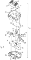
- Figures 4-8 show how the support device 2 comprises a hub 18 and side leg portions 20 and rear leg portions 22 pivoted thereto about axes that are vertical when the shelter is erected. In use, the legs 4, 6 are attached to the respective leg portions 20, 22.
- the support device comprises a base plate 24 which in this example is generally hexagonal.
- the base plate as embodied here has channels 26 for housing arm protrusions 28 for mounting the arms 10.
- the protrusions 28 are fixed to a T-shaped member 30 which is mounted on a lower sub-plate 32 attached to a rear half of the base plate 24.
- the leg portions 20, 22 are pivotally mounted at peripheral locations between the lower sub-plate 32 and an upper sub-plate 34, and are best viewed in Figure 7 .
- a mounting end of the leg portion includes a generally cylindrical mounting part 36 that slidingly rotates relative to the plates 32, 34.
- a latching member 38 extends from an upper surface of the mounting part 36, with a vertical face 42 directed forwardly and a sloping face 44 directed rearwardly.
- An upper part 46 is located centrally with respect to the mounting part 40.
- a vertical bore 48 for mounting the leg portion extends through the upper part 46 and the mounting part 40, and receives a suitable fastener.
- the left and right side leg portions 20 are mutually symmetrical.
- the two rear leg portions 22 can be formed identically to the corresponding side leg portions 20, although the rear leg portions 22 do not require the latching member 36.
- a shroud 50 having the same general footprint as the base plate 24, is attached thereto so as to enclose the mounting ends of the leg portions 20, 22, the sub-plates 32, 24 and the T-shaped member 30.
- a jaw 52 is mounted pivotally near the front of the shroud 50.
- a horizontal bore 54 extends through a lower part of the jaw 48. This bore is aligned with two holes 56 in the shroud 50 so that an axle 58 (an end of which is visible in Figure 4 ) can extend through the bore 54 and the shroud 50.
- the jaw 52 has a generally planar handle 60 at an upper, rear location.
- the jaw has two teeth 62, one on each side, at the back of the jaw and directed downwardly.
- Figure 8 shows a magnet 64, mounted to the right-hand side of the shroud 50 below the jaw 52.
- a further magnet or ferromagnetic contact (not visible) is fixed to the jaw 52 above this magnet.
- a similar pair of magnets or magnetic contacts can be provided on the left-hand side of the shroud 50 and the jaw 52.
- the magnet(s) retain the jaw 52 against the shroud 50, with the teeth 62 abutting the vertical faces 42 of the side leg portions 20 and preventing the side legs 4 from rotating rearwardly.
- the rear legs 6 do not require locking in this way, as they are held in place by the tension in the cover 8.
- the handle 60 is used to raise the jaw 52, pivoting on the axle 58.
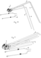
- the teeth 62 disengage from the leg portions 20, and the side legs 4 and rear legs 6 are rotated rearwardly through the position shown in Figure 9 to that of Figure 10 , where the four leg portions 20, 22 are essentially parallel, as viewed from above.
- Figure 11 lower parts of the legs 4, 6 can be removed.
- the legs 4, 6 are assembled and rotated forwardly.
- the teeth 62 slide up the sloping faces 44 of the side leg portions 20.
- the magnet(s) is/are detached as the jaw 52 pivots upwardly, and reattached when the teeth 62 once again engage behind the vertical faces 42.
- the shelter shown in the drawings can stand stably with just four legs. However, for even greater stability, struts interconnecting the legs and/or guy ropes can also be used.
- the jaw can be retained in its clamped position by a spring, such as a helical expansion spring.
- a catch may be provided, which may be releasable by a pushbutton or other mechanism.
- the shelter of the invention is simple to manufacture and can be erected and collapsed simply and quickly.
Landscapes
- Engineering & Computer Science (AREA)
- Architecture (AREA)
- Civil Engineering (AREA)
- Structural Engineering (AREA)
- Tents Or Canopies (AREA)
- Buildings Adapted To Withstand Abnormal External Influences (AREA)
Applications Claiming Priority (1)
| Application Number | Priority Date | Filing Date | Title |
|---|---|---|---|
| GBGB2113051.3A GB202113051D0 (en) | 2021-09-13 | 2021-09-13 | Device for supporting a shelter |
Publications (2)
| Publication Number | Publication Date |
|---|---|
| EP4148208A1 true EP4148208A1 (de) | 2023-03-15 |
| EP4148208B1 EP4148208B1 (de) | 2025-06-25 |
Family
ID=78149317
Family Applications (1)
| Application Number | Title | Priority Date | Filing Date |
|---|---|---|---|
| EP22195106.4A Active EP4148208B1 (de) | 2021-09-13 | 2022-09-12 | Vorrichtung zum stützen eines zeltes |
Country Status (2)
| Country | Link |
|---|---|
| EP (1) | EP4148208B1 (de) |
| GB (1) | GB202113051D0 (de) |
Cited By (1)
| Publication number | Priority date | Publication date | Assignee | Title |
|---|---|---|---|---|
| EP4741608A2 (de) | 2024-11-06 | 2026-05-13 | Fox International Group Limited | Zeltrahmen |
Citations (3)
| Publication number | Priority date | Publication date | Assignee | Title |
|---|---|---|---|---|
| US5046882A (en) * | 1989-09-27 | 1991-09-10 | Bae Jin Corporation | Tent frame folding device |
| GB2535221A (en) | 2015-02-13 | 2016-08-17 | Fox Int Group Ltd | A tent frame |
| US20190338553A1 (en) * | 2018-05-04 | 2019-11-07 | Rio Brands, Llc | Collapsible Tent with Improved Crown Hub Assembly |
-
2021
- 2021-09-13 GB GBGB2113051.3A patent/GB202113051D0/en not_active Ceased
-
2022
- 2022-09-12 EP EP22195106.4A patent/EP4148208B1/de active Active
Patent Citations (3)
| Publication number | Priority date | Publication date | Assignee | Title |
|---|---|---|---|---|
| US5046882A (en) * | 1989-09-27 | 1991-09-10 | Bae Jin Corporation | Tent frame folding device |
| GB2535221A (en) | 2015-02-13 | 2016-08-17 | Fox Int Group Ltd | A tent frame |
| US20190338553A1 (en) * | 2018-05-04 | 2019-11-07 | Rio Brands, Llc | Collapsible Tent with Improved Crown Hub Assembly |
Cited By (1)
| Publication number | Priority date | Publication date | Assignee | Title |
|---|---|---|---|---|
| EP4741608A2 (de) | 2024-11-06 | 2026-05-13 | Fox International Group Limited | Zeltrahmen |
Also Published As
| Publication number | Publication date |
|---|---|
| EP4148208B1 (de) | 2025-06-25 |
| GB202113051D0 (en) | 2021-10-27 |
Similar Documents
| Publication | Publication Date | Title |
|---|---|---|
| US8096312B2 (en) | Erectable shelter with three way awning | |
| US10219605B1 (en) | Wig tree | |
| EP4148208B1 (de) | Vorrichtung zum stützen eines zeltes | |
| US5098050A (en) | Portable decoy stand | |
| US9375090B2 (en) | Rotatable and collapsible chair | |
| US6739936B1 (en) | Toy support apparatus | |
| US12449850B2 (en) | Article mounting apparatus and system comprising same | |
| KR200490275Y1 (ko) | 낚시대용 다용도 거치대 | |
| CN114007457B (zh) | 双遮挡设备 | |
| KR200491306Y1 (ko) | 캠핑용 좌대 | |
| EP2543109A1 (de) | Transportierbare satellitenantenne | |
| US4676471A (en) | Portable stand for a tree | |
| EP3539299B1 (de) | Ständer für mikrofone, lampen und dergleichen | |
| US20080252005A1 (en) | Object holding mechanism | |
| US20040172752A1 (en) | Collapsible hammock frame | |
| US5024414A (en) | Stabilizing device for hand-held/portable electronic device | |
| JP6667804B1 (ja) | 架台 | |
| CA2011491C (en) | Collapsible shelter | |
| US4269499A (en) | Two-piece quadripod for cameras | |
| CN214618945U (zh) | 一种自拍杆 | |
| CN224139034U (zh) | 一种通用手机支架及手机壳 | |
| JP3071642U (ja) | 簡易式万能スタンド | |
| JPH039371Y2 (de) | ||
| JP2002330682A (ja) | 釣り竿支持台 | |
| KR20200145155A (ko) | 다중 배너 거치대 |
Legal Events
| Date | Code | Title | Description |
|---|---|---|---|
| PUAI | Public reference made under article 153(3) epc to a published international application that has entered the european phase |
Free format text: ORIGINAL CODE: 0009012 |
|
| STAA | Information on the status of an ep patent application or granted ep patent |
Free format text: STATUS: THE APPLICATION HAS BEEN PUBLISHED |
|
| AK | Designated contracting states |
Kind code of ref document: A1 Designated state(s): AL AT BE BG CH CY CZ DE DK EE ES FI FR GB GR HR HU IE IS IT LI LT LU LV MC MK MT NL NO PL PT RO RS SE SI SK SM TR |
|
| STAA | Information on the status of an ep patent application or granted ep patent |
Free format text: STATUS: REQUEST FOR EXAMINATION WAS MADE |
|
| 17P | Request for examination filed |
Effective date: 20230831 |
|
| RBV | Designated contracting states (corrected) |
Designated state(s): AL AT BE BG CH CY CZ DE DK EE ES FI FR GB GR HR HU IE IS IT LI LT LU LV MC MK MT NL NO PL PT RO RS SE SI SK SM TR |
|
| GRAP | Despatch of communication of intention to grant a patent |
Free format text: ORIGINAL CODE: EPIDOSNIGR1 |
|
| STAA | Information on the status of an ep patent application or granted ep patent |
Free format text: STATUS: GRANT OF PATENT IS INTENDED |
|
| RIC1 | Information provided on ipc code assigned before grant |
Ipc: E04H 15/48 20060101AFI20250108BHEP |
|
| INTG | Intention to grant announced |
Effective date: 20250122 |
|
| TPAC | Observations filed by third parties |
Free format text: ORIGINAL CODE: EPIDOSNTIPA |
|
| GRAS | Grant fee paid |
Free format text: ORIGINAL CODE: EPIDOSNIGR3 |
|
| GRAA | (expected) grant |
Free format text: ORIGINAL CODE: 0009210 |
|
| STAA | Information on the status of an ep patent application or granted ep patent |
Free format text: STATUS: THE PATENT HAS BEEN GRANTED |
|
| P01 | Opt-out of the competence of the unified patent court (upc) registered |
Free format text: CASE NUMBER: APP_19816/2025 Effective date: 20250424 |
|
| AK | Designated contracting states |
Kind code of ref document: B1 Designated state(s): AL AT BE BG CH CY CZ DE DK EE ES FI FR GB GR HR HU IE IS IT LI LT LU LV MC MK MT NL NO PL PT RO RS SE SI SK SM TR |
|
| REG | Reference to a national code |
Ref country code: GB Ref legal event code: FG4D |
|
| REG | Reference to a national code |
Ref country code: CH Ref legal event code: EP |
|
| REG | Reference to a national code |
Ref country code: CH Ref legal event code: EP |
|
| REG | Reference to a national code |
Ref country code: IE Ref legal event code: FG4D |
|
| REG | Reference to a national code |
Ref country code: DE Ref legal event code: R096 Ref document number: 602022016357 Country of ref document: DE |
|
| REG | Reference to a national code |
Ref country code: NL Ref legal event code: FP |
|
| PG25 | Lapsed in a contracting state [announced via postgrant information from national office to epo] |
Ref country code: FI Free format text: LAPSE BECAUSE OF FAILURE TO SUBMIT A TRANSLATION OF THE DESCRIPTION OR TO PAY THE FEE WITHIN THE PRESCRIBED TIME-LIMIT Effective date: 20250625 |
|
| PGFP | Annual fee paid to national office [announced via postgrant information from national office to epo] |
Ref country code: DE Payment date: 20250918 Year of fee payment: 4 |
|
| REG | Reference to a national code |
Ref country code: LT Ref legal event code: MG9D |
|
| PG25 | Lapsed in a contracting state [announced via postgrant information from national office to epo] |
Ref country code: NO Free format text: LAPSE BECAUSE OF FAILURE TO SUBMIT A TRANSLATION OF THE DESCRIPTION OR TO PAY THE FEE WITHIN THE PRESCRIBED TIME-LIMIT Effective date: 20250925 Ref country code: GR Free format text: LAPSE BECAUSE OF FAILURE TO SUBMIT A TRANSLATION OF THE DESCRIPTION OR TO PAY THE FEE WITHIN THE PRESCRIBED TIME-LIMIT Effective date: 20250926 |
|
| PGFP | Annual fee paid to national office [announced via postgrant information from national office to epo] |
Ref country code: NL Payment date: 20250917 Year of fee payment: 4 |
|
| PG25 | Lapsed in a contracting state [announced via postgrant information from national office to epo] |
Ref country code: BG Free format text: LAPSE BECAUSE OF FAILURE TO SUBMIT A TRANSLATION OF THE DESCRIPTION OR TO PAY THE FEE WITHIN THE PRESCRIBED TIME-LIMIT Effective date: 20250625 |
|
| PG25 | Lapsed in a contracting state [announced via postgrant information from national office to epo] |
Ref country code: HR Free format text: LAPSE BECAUSE OF FAILURE TO SUBMIT A TRANSLATION OF THE DESCRIPTION OR TO PAY THE FEE WITHIN THE PRESCRIBED TIME-LIMIT Effective date: 20250625 |
|
| PGFP | Annual fee paid to national office [announced via postgrant information from national office to epo] |
Ref country code: FR Payment date: 20250925 Year of fee payment: 4 Ref country code: AT Payment date: 20251020 Year of fee payment: 4 |
|
| PG25 | Lapsed in a contracting state [announced via postgrant information from national office to epo] |
Ref country code: RS Free format text: LAPSE BECAUSE OF FAILURE TO SUBMIT A TRANSLATION OF THE DESCRIPTION OR TO PAY THE FEE WITHIN THE PRESCRIBED TIME-LIMIT Effective date: 20250925 |
|
| PG25 | Lapsed in a contracting state [announced via postgrant information from national office to epo] |
Ref country code: LV Free format text: LAPSE BECAUSE OF FAILURE TO SUBMIT A TRANSLATION OF THE DESCRIPTION OR TO PAY THE FEE WITHIN THE PRESCRIBED TIME-LIMIT Effective date: 20250625 |
|
| PG25 | Lapsed in a contracting state [announced via postgrant information from national office to epo] |
Ref country code: PT Free format text: LAPSE BECAUSE OF FAILURE TO SUBMIT A TRANSLATION OF THE DESCRIPTION OR TO PAY THE FEE WITHIN THE PRESCRIBED TIME-LIMIT Effective date: 20251027 |
|
| REG | Reference to a national code |
Ref country code: AT Ref legal event code: MK05 Ref document number: 1806584 Country of ref document: AT Kind code of ref document: T Effective date: 20250625 |
|
| PG25 | Lapsed in a contracting state [announced via postgrant information from national office to epo] |
Ref country code: IS Free format text: LAPSE BECAUSE OF FAILURE TO SUBMIT A TRANSLATION OF THE DESCRIPTION OR TO PAY THE FEE WITHIN THE PRESCRIBED TIME-LIMIT Effective date: 20251025 |
|
| PG25 | Lapsed in a contracting state [announced via postgrant information from national office to epo] |
Ref country code: AT Free format text: LAPSE BECAUSE OF FAILURE TO SUBMIT A TRANSLATION OF THE DESCRIPTION OR TO PAY THE FEE WITHIN THE PRESCRIBED TIME-LIMIT Effective date: 20250625 Ref country code: SM Free format text: LAPSE BECAUSE OF FAILURE TO SUBMIT A TRANSLATION OF THE DESCRIPTION OR TO PAY THE FEE WITHIN THE PRESCRIBED TIME-LIMIT Effective date: 20250625 |
|
| PG25 | Lapsed in a contracting state [announced via postgrant information from national office to epo] |
Ref country code: CZ Free format text: LAPSE BECAUSE OF FAILURE TO SUBMIT A TRANSLATION OF THE DESCRIPTION OR TO PAY THE FEE WITHIN THE PRESCRIBED TIME-LIMIT Effective date: 20250625 |
|
| PG25 | Lapsed in a contracting state [announced via postgrant information from national office to epo] |
Ref country code: PL Free format text: LAPSE BECAUSE OF FAILURE TO SUBMIT A TRANSLATION OF THE DESCRIPTION OR TO PAY THE FEE WITHIN THE PRESCRIBED TIME-LIMIT Effective date: 20250625 |
|
| PG25 | Lapsed in a contracting state [announced via postgrant information from national office to epo] |
Ref country code: EE Free format text: LAPSE BECAUSE OF FAILURE TO SUBMIT A TRANSLATION OF THE DESCRIPTION OR TO PAY THE FEE WITHIN THE PRESCRIBED TIME-LIMIT Effective date: 20250625 |
|
| PG25 | Lapsed in a contracting state [announced via postgrant information from national office to epo] |
Ref country code: SK Free format text: LAPSE BECAUSE OF FAILURE TO SUBMIT A TRANSLATION OF THE DESCRIPTION OR TO PAY THE FEE WITHIN THE PRESCRIBED TIME-LIMIT Effective date: 20250625 |
|
| PG25 | Lapsed in a contracting state [announced via postgrant information from national office to epo] |
Ref country code: ES Free format text: LAPSE BECAUSE OF FAILURE TO SUBMIT A TRANSLATION OF THE DESCRIPTION OR TO PAY THE FEE WITHIN THE PRESCRIBED TIME-LIMIT Effective date: 20250625 |
|
| PG25 | Lapsed in a contracting state [announced via postgrant information from national office to epo] |
Ref country code: RO Free format text: LAPSE BECAUSE OF FAILURE TO SUBMIT A TRANSLATION OF THE DESCRIPTION OR TO PAY THE FEE WITHIN THE PRESCRIBED TIME-LIMIT Effective date: 20250625 |
|
| PG25 | Lapsed in a contracting state [announced via postgrant information from national office to epo] |
Ref country code: DK Free format text: LAPSE BECAUSE OF FAILURE TO SUBMIT A TRANSLATION OF THE DESCRIPTION OR TO PAY THE FEE WITHIN THE PRESCRIBED TIME-LIMIT Effective date: 20250625 |
|
| PG25 | Lapsed in a contracting state [announced via postgrant information from national office to epo] |
Ref country code: IT Free format text: LAPSE BECAUSE OF FAILURE TO SUBMIT A TRANSLATION OF THE DESCRIPTION OR TO PAY THE FEE WITHIN THE PRESCRIBED TIME-LIMIT Effective date: 20250625 |
|
| PLBE | No opposition filed within time limit |
Free format text: ORIGINAL CODE: 0009261 |
|
| STAA | Information on the status of an ep patent application or granted ep patent |
Free format text: STATUS: NO OPPOSITION FILED WITHIN TIME LIMIT |
|
| REG | Reference to a national code |
Ref country code: CH Ref legal event code: H13 Free format text: ST27 STATUS EVENT CODE: U-0-0-H10-H13 (AS PROVIDED BY THE NATIONAL OFFICE) Effective date: 20260504 |
|
| REG | Reference to a national code |
Ref country code: CH Ref legal event code: L10 Free format text: ST27 STATUS EVENT CODE: U-0-0-L10-L00 (AS PROVIDED BY THE NATIONAL OFFICE) Effective date: 20260507 |